

Page 1
nualrature Monitoring System
EN) manual
New Brunswick™ TCA-3
Temperature Monitoring System
Operating manual
Page 2

Copyright
Copyright © 2014 Eppendorf AG, Germany. No part of this publication may be reproduced without the
prior permission of the copyright owner.
The company reserves the right to change information in this document without notice. Updates to
information in this document reflect our commitment to continuing product development and
improvement.
Trademarks
®
Eppendorf
and the Eppendorf logo are registered trademarks of Eppendorf AG, Germany.
New Brunswick™ and the New Brunswick™ logo are trademarks of Eppendorf AG, Germany.
®
VeriSign Secured
is a registered trademark of VeriSign, Inc., USA
Microsoft
®
and Excel® are either registered trademarks or trademarks of Microsoft Corporation in the
United States and/or other countries.
®
Trademarks are not marked in all cases with ™ or
in this manual.
Eppendorf has attempted to identify the ownership of all trademarks from public records. Any omissions or
errors are unintentional.
M1288-0059-C/012014
Page 3

Table of contents
TCA-3 Temperature Monitoring System
English (EN)
Table of contents
1 Operating instructions . . . . . . . . . . . . . . . . . . . . . . . . . . . . . . . . . . . . . . . . . . . . . . . . . . . . . . . . . . . . . . 5
1.1 Using this manual . . . . . . . . . . . . . . . . . . . . . . . . . . . . . . . . . . . . . . . . . . . . . . . . . . . . . . . . . . . . . 5
1.2 Symbols used . . . . . . . . . . . . . . . . . . . . . . . . . . . . . . . . . . . . . . . . . . . . . . . . . . . . . . . . . . . . . . . . 5
2 Product description . . . . . . . . . . . . . . . . . . . . . . . . . . . . . . . . . . . . . . . . . . . . . . . . . . . . . . . . . . . . . . . . 7
2.1 Delivery package. . . . . . . . . . . . . . . . . . . . . . . . . . . . . . . . . . . . . . . . . . . . . . . . . . . . . . . . . . . . . . 7
2.1.1 Hardware checklist . . . . . . . . . . . . . . . . . . . . . . . . . . . . . . . . . . . . . . . . . . . . . . . . . . . . . 7
2.1.2 Inspection of boxes . . . . . . . . . . . . . . . . . . . . . . . . . . . . . . . . . . . . . . . . . . . . . . . . . . . . . 7
2.1.3 Packing list verification . . . . . . . . . . . . . . . . . . . . . . . . . . . . . . . . . . . . . . . . . . . . . . . . . . 7
3 Installation . . . . . . . . . . . . . . . . . . . . . . . . . . . . . . . . . . . . . . . . . . . . . . . . . . . . . . . . . . . . . . . . . . . . . . . 9
3.1 Mounting the TCA-3 temperature monitoring system . . . . . . . . . . . . . . . . . . . . . . . . . . . . . . . . . 9
3.2 Inserting the probe . . . . . . . . . . . . . . . . . . . . . . . . . . . . . . . . . . . . . . . . . . . . . . . . . . . . . . . . . . . . 9
3.3 Reconnecting probes to the TCA-3 temperature monitoring system . . . . . . . . . . . . . . . . . . . . . . 9
3.4 Connecting the power supply . . . . . . . . . . . . . . . . . . . . . . . . . . . . . . . . . . . . . . . . . . . . . . . . . . . 10
3.4.1 Standard mains/power supply. . . . . . . . . . . . . . . . . . . . . . . . . . . . . . . . . . . . . . . . . . . . 10
3.4.2 Power Over Ethernet (POE). . . . . . . . . . . . . . . . . . . . . . . . . . . . . . . . . . . . . . . . . . . . . . 10
3
4 Operation. . . . . . . . . . . . . . . . . . . . . . . . . . . . . . . . . . . . . . . . . . . . . . . . . . . . . . . . . . . . . . . . . . . . . . . . 11
4.1 LED guide . . . . . . . . . . . . . . . . . . . . . . . . . . . . . . . . . . . . . . . . . . . . . . . . . . . . . . . . . . . . . . . . . . 11
4.2 IT information . . . . . . . . . . . . . . . . . . . . . . . . . . . . . . . . . . . . . . . . . . . . . . . . . . . . . . . . . . . . . . . 11
4.3 Internet security . . . . . . . . . . . . . . . . . . . . . . . . . . . . . . . . . . . . . . . . . . . . . . . . . . . . . . . . . . . . . 12
4.4 Login . . . . . . . . . . . . . . . . . . . . . . . . . . . . . . . . . . . . . . . . . . . . . . . . . . . . . . . . . . . . . . . . . . . . . . 13
4.4.1 Creating your account . . . . . . . . . . . . . . . . . . . . . . . . . . . . . . . . . . . . . . . . . . . . . . . . . . 13
4.4.2 Login to your account . . . . . . . . . . . . . . . . . . . . . . . . . . . . . . . . . . . . . . . . . . . . . . . . . . 14
4.4.3 Account setup . . . . . . . . . . . . . . . . . . . . . . . . . . . . . . . . . . . . . . . . . . . . . . . . . . . . . . . . 15
4.5 Software navigation. . . . . . . . . . . . . . . . . . . . . . . . . . . . . . . . . . . . . . . . . . . . . . . . . . . . . . . . . . . 20
4.6 Account settings . . . . . . . . . . . . . . . . . . . . . . . . . . . . . . . . . . . . . . . . . . . . . . . . . . . . . . . . . . . . . 21
4.6.1 Primary contact . . . . . . . . . . . . . . . . . . . . . . . . . . . . . . . . . . . . . . . . . . . . . . . . . . . . . . . 21
4.6.2 User accounts . . . . . . . . . . . . . . . . . . . . . . . . . . . . . . . . . . . . . . . . . . . . . . . . . . . . . . . . 22
4.6.3 Default alarm contact . . . . . . . . . . . . . . . . . . . . . . . . . . . . . . . . . . . . . . . . . . . . . . . . . . 22
4.7 Latest measurements . . . . . . . . . . . . . . . . . . . . . . . . . . . . . . . . . . . . . . . . . . . . . . . . . . . . . . . . . 23
4.8 Gateway preferences icon. . . . . . . . . . . . . . . . . . . . . . . . . . . . . . . . . . . . . . . . . . . . . . . . . . . . . . 24
4.8.1 General tab . . . . . . . . . . . . . . . . . . . . . . . . . . . . . . . . . . . . . . . . . . . . . . . . . . . . . . . . . . 24
4.8.2 Info tab . . . . . . . . . . . . . . . . . . . . . . . . . . . . . . . . . . . . . . . . . . . . . . . . . . . . . . . . . . . . . 24
4.8.3 View tab . . . . . . . . . . . . . . . . . . . . . . . . . . . . . . . . . . . . . . . . . . . . . . . . . . . . . . . . . . . . 25
4.9 Gateway alarms. . . . . . . . . . . . . . . . . . . . . . . . . . . . . . . . . . . . . . . . . . . . . . . . . . . . . . . . . . . . . . 26
4.10 Sensor preferences . . . . . . . . . . . . . . . . . . . . . . . . . . . . . . . . . . . . . . . . . . . . . . . . . . . . . . . . . . . 27
4.10.1 General tab . . . . . . . . . . . . . . . . . . . . . . . . . . . . . . . . . . . . . . . . . . . . . . . . . . . . . . . . . . 27
4.10.2 Info tab . . . . . . . . . . . . . . . . . . . . . . . . . . . . . . . . . . . . . . . . . . . . . . . . . . . . . . . . . . . . . 28
4.10.3 Advanced tab. . . . . . . . . . . . . . . . . . . . . . . . . . . . . . . . . . . . . . . . . . . . . . . . . . . . . . . . . 28
4.11 Sensor alarms . . . . . . . . . . . . . . . . . . . . . . . . . . . . . . . . . . . . . . . . . . . . . . . . . . . . . . . . . . . . . . . 29
4.11.1 General tab . . . . . . . . . . . . . . . . . . . . . . . . . . . . . . . . . . . . . . . . . . . . . . . . . . . . . . . . . . 29
4.11.2 Trigger tab. . . . . . . . . . . . . . . . . . . . . . . . . . . . . . . . . . . . . . . . . . . . . . . . . . . . . . . . . . . 31
4.12 Sensor graph . . . . . . . . . . . . . . . . . . . . . . . . . . . . . . . . . . . . . . . . . . . . . . . . . . . . . . . . . . . . . . . . 32
4.12.1 Main graph . . . . . . . . . . . . . . . . . . . . . . . . . . . . . . . . . . . . . . . . . . . . . . . . . . . . . . . . . . 33
4.12.2 Change data range . . . . . . . . . . . . . . . . . . . . . . . . . . . . . . . . . . . . . . . . . . . . . . . . . . . . 34
4.12.3 Multiple traces on a graph . . . . . . . . . . . . . . . . . . . . . . . . . . . . . . . . . . . . . . . . . . . . . . 34
Page 4

Table of contents
TCA-3 Temperature Monitoring System
4
English (EN)
4.12.4 Download to Excel . . . . . . . . . . . . . . . . . . . . . . . . . . . . . . . . . . . . . . . . . . . . . . . . . . . . 36
5 Troubleshooting . . . . . . . . . . . . . . . . . . . . . . . . . . . . . . . . . . . . . . . . . . . . . . . . . . . . . . . . . . . . . . . . . . 39
5.1 General errors . . . . . . . . . . . . . . . . . . . . . . . . . . . . . . . . . . . . . . . . . . . . . . . . . . . . . . . . . . . . . . . 39
6 Calibration instructions . . . . . . . . . . . . . . . . . . . . . . . . . . . . . . . . . . . . . . . . . . . . . . . . . . . . . . . . . . . . 43
6.1 Calibration requirements . . . . . . . . . . . . . . . . . . . . . . . . . . . . . . . . . . . . . . . . . . . . . . . . . . . . . . 43
6.2 Single point calibration . . . . . . . . . . . . . . . . . . . . . . . . . . . . . . . . . . . . . . . . . . . . . . . . . . . . . . . . 43
6.3 Two point calibration . . . . . . . . . . . . . . . . . . . . . . . . . . . . . . . . . . . . . . . . . . . . . . . . . . . . . . . . . 44
6.3.1 Using Excel for calculation . . . . . . . . . . . . . . . . . . . . . . . . . . . . . . . . . . . . . . . . . . . . . . 45
7 Certificates . . . . . . . . . . . . . . . . . . . . . . . . . . . . . . . . . . . . . . . . . . . . . . . . . . . . . . . . . . . . . . . . . . . . . . 47
Page 5

Operating instructions
TCA-3 Temperature Monitoring System
English (EN)
1 Operating instructions
1.1 Using this manual
Carefully read this operating manual before using the device for the first time.
Also observe the operating manual enclosed with the accessories.
The operating manual should be considered as part of the product and stored in a location that is easily
accessible.
When passing the device on to third parties, be sure to include this operating manual.
If this manual is lost, please request another one. The latest version can be found on our website
www.eppendorf.com (international) or www.eppendorfna.com (North America).
1.2 Symbols used
Example Meaning
You are requested to perform an action.
1.
2.
• List.
Perform these actions in the sequence described.
References useful information.
5
Page 6

Operating instructions
TCA-3 Temperature Monitoring System
6
English (EN)
Page 7
2 Product description
2.1 Delivery package
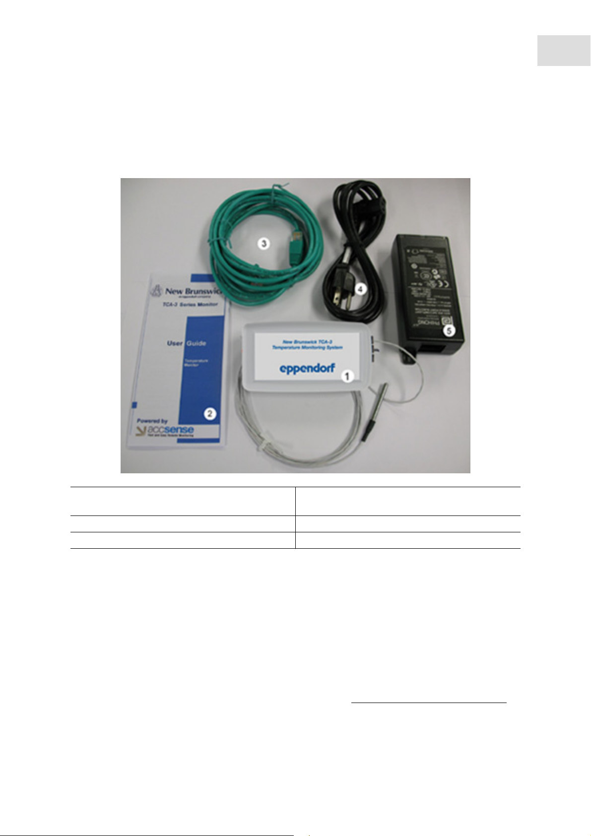
2.1.1 Hardware checklist
Product description
TCA-3 Temperature Monitoring System
English (EN)
7
1. TCA-3 monitoring system complete with ambient
and freezer temperature probes
2. User guide 5. Mains/Power adaptor
3. 2 x Ethernet patch cables
4. Mains/Power cord
2.1.2 Inspection of boxes
Inspect the boxes carefully for any damage that may have occurred during shipping. Report any damage to
the carrier and to your local Eppendorf Sales Order Department immediately.
2.1.3 Packing list verification
Unpack your order, saving the packing materials for possible future use. Save the operating manual for
instruction and reference. Verify against your packing list that you have received the correct materials, and
that nothing is missing. If any part of your order was damaged during shipping, is missing, or fails to
operate, fill out the "Customer Feedback" form, available online at
http://newbrunswick.eppendorf.com/.
Page 8

Product description
TCA-3 Temperature Monitoring System
8
English (EN)
Page 9
Installation
TCA-3 Temperature Monitoring System
English (EN)
3 Installation
3.1 Mounting the TCA-3 temperature monitoring system
The TCA-3 temperature monitoring system can be mounted using the Velcro supplied. The monitoring
system should be placed such that the End Plate (with the LEDs) is visible.
3.2 Inserting the probe
Place the temperature probe(s) into the area to be measured using the access port on the back of the
freezer, or by running the lead through the door seal on the hinge side of the freezer door.
Secure the probe to a suitable fixed location e.g. shelf, with a cable tie.
Inside temperature of freezers and refrigerators varies within the chambers. Probe location
within the refrigerator/freezer WILL affect the temperature reading. We recommend using a
thermal dampener or liquid to simulate the product in the refrigerator/freezer.
9
3.3 Reconnecting probes to the TCA-3 temperature monitoring system
The TCA-3 temperature monitoring system is supplied with the probes connected. Use the
following steps to reconnected the probes to the monitoring system if they become
disconnected.
1. Slide open the access door at the bottom of the TCA-3 temperature monitoring system.
2. Insert the probes through the holes in the side of the case.
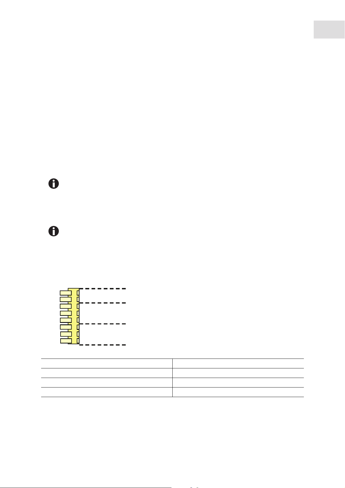
The probe connection block shows connections for the 2 RTD and “T” type thermocouple probes.
A
1
2
3
3
4
3
3
4
A. Connector 1. TC+
B. ‘T’ Type Thermocouple 2. GND/TC-
C. RTD Probe number #2 3. Black or White
D. RTD Probe number #1 4. Red
B
C
D
3. Push down the tab on the connector and insert the stripped end of the probe into the connector, taking
note of the color.
Page 10
10
Installation
TCA-3 Temperature Monitoring System
English (EN)
3.4 Connecting the power supply
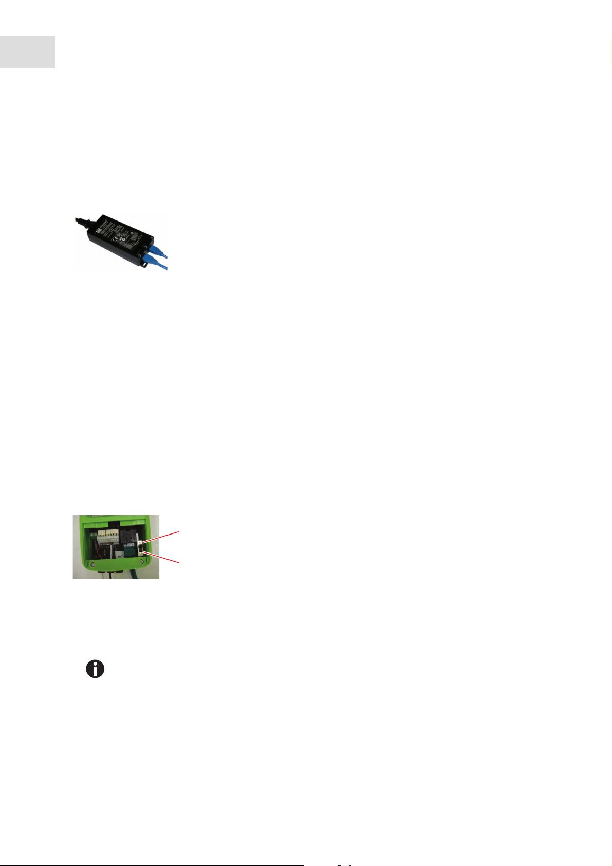
3.4.1 Standard mains/power supply
1. Connect the TCA-3 temperature monitoring system to the Power Injector by inserting one end of an
Ethernet cable into the port on the back of the TCA-3 temperature monitoring system and the other into
the OUT port of the Power Injector.
2. Insert the second Ethernet cable into the IN port of the Power Injector and connect the other end of the
cable to a LAN port.
3. Plug the Power Injector into 100-240 VAC mains/power outlet using the mains/power cord supplied.
3.4.2 Power Over Ethernet (POE)
For Power-Over-Ethernet LANs, no Power Injector is necessary.
Connect the TCA-3 temperature monitoring system directly into the network which supports Power
Over Ethernet (POE).
3.4.3 Turning power supply switch On
1. Remove the TCA-3 temperature monitoring system from the refrigerator/freezer by separating the
Velcro.
2. Slide open the access door on the bottom of the TCA-3 temperature monitoring system.
1
2
1 On 2 Off
3. Slide the On-Off switch to the On position.
Follow standard mains/power supply or Power Over Ethernet instructions below.
Page 11
4 Operation
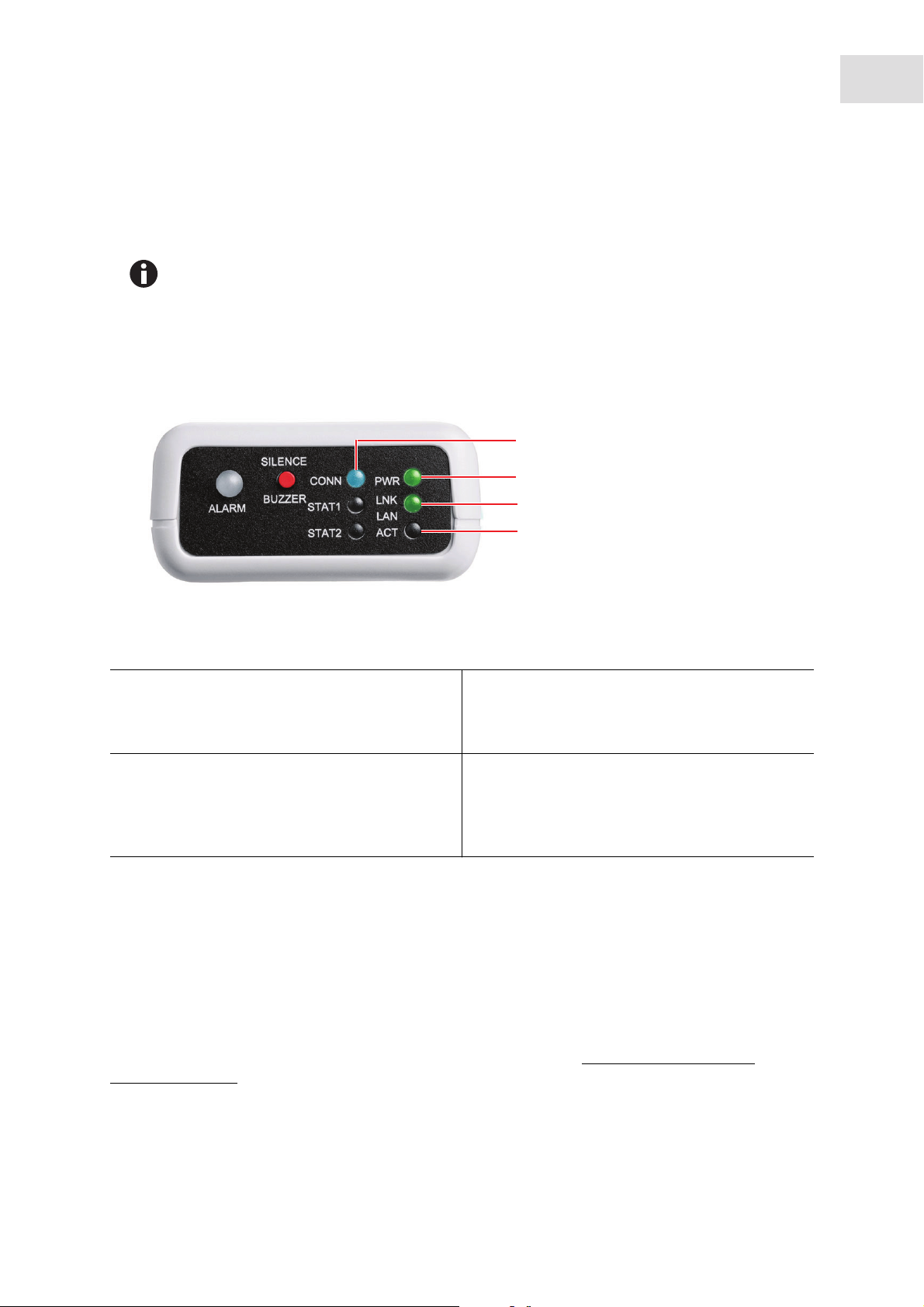
4.1 LED guide
1. The internal battery powers down during shipment to save power. Disregard the initial
“Internal Battery Low Voltage” alarm.
2. A solid blue “CONN” light indicates that Secure Server has received the last
communication.
A flashing “CONN” light indicates communication with Secure Servers.
TCA-3 Temperature Monitoring System
English (EN)
1
2
3
Operation
11
4
1. CONN
The CONN LED will flash blue when communicating
to the server and solid blue when last
communication is successful.
2. PWR
The PWR LED will appear solid green when the 5 V
mains/power supply is working, flashing fast green
when on internal battery power, or flashing slow
green when the internal battery is low (4-Hour life).
3. LNK LAN
The LNK LAN LED will appear solid green when the
LAN hardware connection is good.
4. ACT
The ACT LED will flash green when communicating
with the LAN.
4.2 IT information
The TCA-3 monitoring system is plug and play with the following settings:
• The server is DHCP.
• A Proxy server is not being used.
• The MAC address does not require registering.
The TCA-3 monitoring system can be set with a fixed IP address, this can be done with the Remote Gateway
Configuration Utility which can be downloaded from the following link:
sp_downloads.html
http://www.accsense.com/
Page 12

12
Operation
TCA-3 Temperature Monitoring System
English (EN)
The TCA-3 monitoring system supports SOCKS4 and SOCKS5 Proxy servers, which can be set up using the
Remote Gateway Configuration Utility. In environments where other proxy servers are used, a router may
be required to act as a proxy client for the TCA-3 monitoring system.
Generally MAC numbers do not require registering on the network; if it is a requirement, register the
unique MAC number for each TCA-3 monitoring system.
All communication to the hosts will be initiated from the TCA-3 monitoring system using HTTPS on port
443.
The TCA-3 monitoring system does not need to accept incoming sockets from the hosts, only to be able to
open sockets to them.
All traffic is initiated from the TCA-3 monitoring system as out going secure web requests.
Aside from needing access to DNS servers, the TCA-3 monitoring system will not communicate with any
other hosts on the Internet.
Useful destination addresses for communications for the TCA-3 monitoring system web application are as
follows:
• 8.26.65.62 listener.sensornetworkonline.com
• 83.26.65.62 secure.sensornetworkonline.com
4.3 Internet security
Communication from the TCA-3 monitoring system to the Secure Servers utilizes the HTTPS protocol and
only relies on an outbound connection over port 443. As communication between the TCA-3 monitoring
system and the servers is initiated from the TCA-3 monitoring system, there is no need to open inbound
ports on the firewall. HTTPS over port 443 is a standard communications protocol for secure Web traffic
(e.g. credit card transactions).
Data sent over the Internet utilizes two forms of encryption:
• SSL Encryption, the same "padlock" feature that many Web sites use to ensure Web purchases are
secure.
• Certificate Encryption, each gateway is issued a unique, digitally signed certificate that is associated
with its serial number.
Page 13
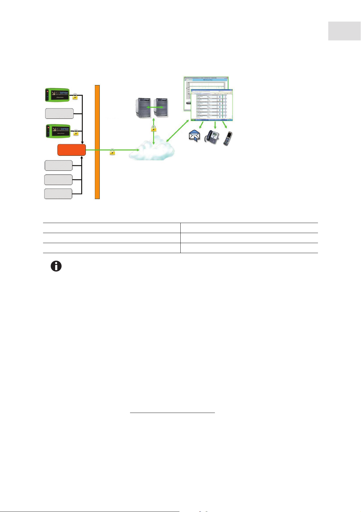
Abb. 4-1: LAN-Wired IT security
Operation
TCA-3 Temperature Monitoring System
13
English (EN)
A
1
C
2
1
D
1
1
B
Fig. 4-1: LAN-Wired IT security
A. Rackspace secure servers D. LAN
B. Internet 1. Customer computer
C. Customer firewall 2. Customer router
SSL and Certificate Encryption keeps your data safe from collection to transmission and
storage in our Rackspace Secure Servers.
A combination of SSL and Certificate Encryption ensures the data has the highest level of security over the
internet. Only devices with the SSL and Certificate Encryption digital signature are permitted to connect to
®
the. Our Website is VeriSign Secured
, providing leading encryption and identity verification.
If a certificate is compromised, its unique signature can be revoked, making this virtually unexploitable to
system hackers. These two forms of encryption prevent security problems such as Denial of Service attacks.
Secondly, it is virtually impossible to maliciously insert or spoof data ensuring accurate data.
4.4 Login
4.4.1 Creating your account
Your Eppendorf web service account is created automatically as soon as the TCA-3 monitoring system
contacts the secure server (indicated by a solid blue LED on the front of the TCA-3 monitoring system). The
account will not exist until this first communication contact is made successfully.
You can login to your account via
www.eppendorf.com/TCAStartup, then clicking Customer Login.
Page 14

14
Operation
TCA-3 Temperature Monitoring System
English (EN)
4.4.2 Login to your account
Abb. 4-2: Login screen
Fig. 4-2: Login screen
You can login to your account with the Gateway MAC number (found on the side of the TCA-3 monitoring
system) and the default Login Name and Password:
Login Name: Admin
Password: Admin
Both the Login Name and Password are case sensitive.
Your PC will remember the Gateway Mac number if you check the box.
Page 15
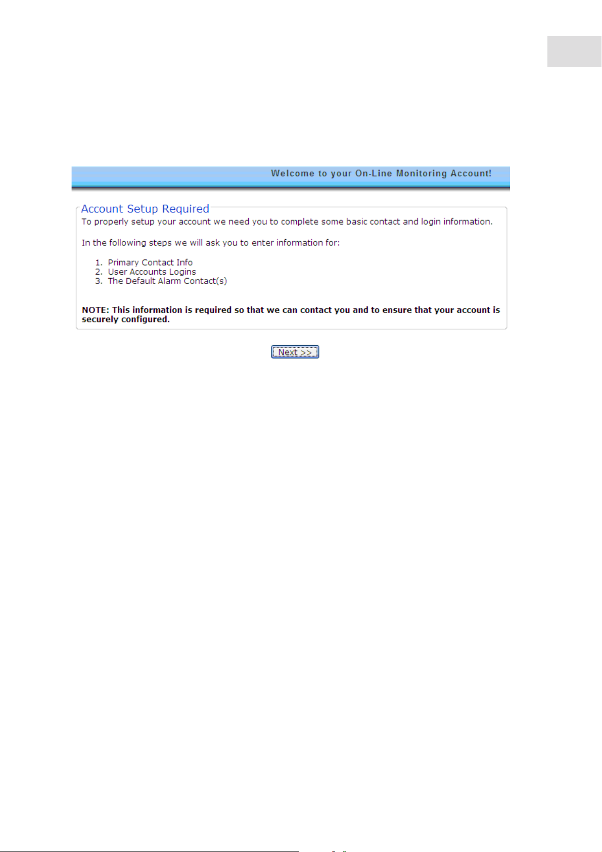
4.4.3 Account setup
1. Login to account, then click next.
Operation
TCA-3 Temperature Monitoring System
English (EN)
15
2. Enter Primary Contact information, then click next.
Page 16

16
Operation
TCA-3 Temperature Monitoring System
English (EN)
3. Enter desired password, then click next.
Page 17

Operation
TCA-3 Temperature Monitoring System
English (EN)
17
4. Click Add Email to enter default email addresses.
Page 18

18
Operation
TCA-3 Temperature Monitoring System
English (EN)
5. Click Add Number to enter default phone numbers.
Page 19

Operation
TCA-3 Temperature Monitoring System
English (EN)
19
6. Click Done
Only phone numbers for the country and country code added during setup will be preselected
in the Default Phone List. To change or add phone numbers for a different country, contact
Eppendorf.
Page 20

20
Operation
TCA-3 Temperature Monitoring System
English (EN)
4.5 Software navigation
The main screen is divided into four areas.
1. User Information/Account Settings 3. Latest Measurements
2. Triggered Alarms 4. Alarm History
Clicking on the icons from the main screen brings up pop up windows.
The browser must be set to allow pop ups from the Eppendorf web site.
Page 21

Operation
TCA-3 Temperature Monitoring System
English (EN)
21
Closing a pop up window returns the user to the main screen.
4.6 Account settings
The Account Settings pop up has three tabs.
4.6.1 Primary contact
The Primary Contact tab provides information that can be used by Eppendorf if the need arises to contact
the customer for any reason. It is important for the users to keep this information up to date.
Page 22

22
Operation
TCA-3 Temperature Monitoring System
English (EN)
4.6.2 User accounts
The User Accounts tab allows two levels of system access to be created:
• Administrator - Administrator can change any parameters such as alarm levels, details of the alarm
contacts, etc.
• Reader-only - Reader-only can only view the information from the system, and cannot change any
system parameters.
If the Administrator forgets their password, contact Eppendorf to have the password reset.
4.6.3 Default alarm contact
The Default Alarm Contact tab contains a list of E-mail addresses, and/or phone numbers. When enabled,
phone numbers can be called in *sequence rather than all at once by selecting Default List when enabling
an alarm for a sensor.
Alarms will be sent once per event, unless sequential alarming mode is selected.
In *sequential alarming mode, the list will be repeated twice if no user takes responsibility by pressing 5.
Page 23

Operation
TCA-3 Temperature Monitoring System
English (EN)
23
*sequential notification is currently only available in the US and the UK.
Only phone numbers for the country added during setup will be preselected in the Default
Phone List. To add phone numbers for a different country, contact Eppendorf.
4.7 Latest measurements
The Latest measurements area of the main window displays the measurements set as visible in the Gateway
Preferences View tab.
Multiple TCA-3 monitoring systems can be displayed in the same window, and merged
accounts can be accessed by a single login.
Contact Eppendorf for information on merging accounts.
Page 24

24
Operation
TCA-3 Temperature Monitoring System
English (EN)
4.8 Gateway preferences icon
4.8.1 General tab
The General tab allows the users to name the TCA-3 monitoring system (TCA-3 monitoring systems will be
listed on the screen in alphabetical order), set the sampling rates (how often measurements are made) and
record notes about the TCA-3 monitoring system.
The following sampling rates can be selected:
• Store data every: This option records data if the measurements are within limits which can be slower
• Check for alarm every: This option checks measurements against alarm limits which can be faster
4.8.2 Info tab
The Info tab provides information about the TCA-3 monitoring system and firmware. This information can
be useful when diagnosing system problems remotely.
Page 25

Operation
TCA-3 Temperature Monitoring System
English (EN)
25
4.8.3 View tab
View tab allows users to set which measurements are:
• Visible (Displayed in measurement window)
• Hidden (Recorded but not displayed)
• Disabled (Not recorded or displayed)
Page 26

26
Operation
TCA-3 Temperature Monitoring System
English (EN)
4.9 Gateway alarms
The Gateway alarm window allows users to set alarms which are triggered if the secure remote servers lose
contact with the TCA-3 monitoring system.
Only one alarm is issued in the event of loss of communication.
Page 27

4.10 Sensor preferences
Abb. 4-3: Preferences icon
Operation
TCA-3 Temperature Monitoring System
English (EN)
27
Fig. 4-3: Preferences icon
4.10.1 General tab
The General tab allows users to name the sensor and select or enter the measurement units.
Page 28

28
Operation
TCA-3 Temperature Monitoring System
English (EN)
4.10.2 Info tab
The Info tab provides information such as Sensor Type and measurement units of the sensor.
4.10.3 Advanced tab
The Advanced tab provides calibration information about the sensor.
Page 29

4.11 Sensor alarms
Abb. 4-4: Sensor alarm icon
Operation
TCA-3 Temperature Monitoring System
English (EN)
29
Fig. 4-4: Sensor alarm icon
4.11.1 General tab
The General tab allows users to enable, disable, and name alarms.
The alarm name will be carried by voice alarms
The Notify List of the Alarm Definition General tab allows users to specify the default or custom list of users
who will be notified of the alarm for this sensor only.
Page 30

30
Operation
TCA-3 Temperature Monitoring System
English (EN)
4.11.1.1 Adding custom notification list
Adding a custom notification list will enable and display the Email List tab and Phone List tab.
Only phone numbers from the preselected country can be added to the phone list. To add
phone numbers for a different country, contact Eppendorf.
Page 31

Operation
TCA-3 Temperature Monitoring System
English (EN)
31
1. Select Custom list from the Notify List field on general tab.
2. Add Email address and phone number to the list.
4.11.2 Trigger tab
The Trigger tab allows users to specify the conditions under which an alarm will be sounded.
The trigger mode of Auto-Rearm means that every time an alarm is triggered an alarm will be sounded. For
Example, if an alarm condition is triggered one after the other, two alarms will be heard.
The filter setting of more than 1 occurrence means that the alarm condition must exist for more than ONE
measurement. This prevents multiple alarms being sent for what really is a single alarm event.
Page 32

32
Operation
TCA-3 Temperature Monitoring System
English (EN)
4.12 Sensor graph
Abb. 4-5: Sensor graph icon
Fig. 4-5: Sensor graph icon
Graphing application uses Flash animation, and will not display on iPhones, iPads, Mac PC’s,
or other devices that do not support Flash. Data Logs with tabular data will be visible.
Page 33

Operation
TCA-3 Temperature Monitoring System
English (EN)
4.12.1 Main graph
The Sensor Graph Icon brings up a pop up graph with a default time window of 1 day. Statistics for the data
displayed are located across the top of the graph. If alarms are set, red bars will appear across the graph at
the one or two alarm levels set.
33
Page 34

34
Operation
TCA-3 Temperature Monitoring System
English (EN)
4.12.2 Change data range
To view data for specific ranges of values and time:
1. Click on the small arrow at the bottom of the graph to open the manual range selection area.
2. Set the ranges as desired, then press the Reload button.
The Duration of the data displayed on the graph can be changed to Hours, Days, or Months with up to 3
Months of data being displayed on the graph at any one time.
This can be changed by clicking on the drop down arrows for the Duration times and then clicking on
Reload.
The graph can display a maximum of 360 data points. When this has been reached there will
be a footnote under the lower right hand side of the graph to signify that the data has been
condensed to fit the screen. Even though the data is condensed it is done so any spikes will be
viewable.
4.12.3 Multiple traces on a graph
It is possible to display more than one trace on a graph for each TCA-3 monitoring system, this could be
used to compare temperature graphs from two different probes.
Page 35

Operation
TCA-3 Temperature Monitoring System
English (EN)
1. In the Latest Measurements click on the graph icon for the TCA-3 monitoring system.
2. Highlight the required sensors to be displayed in the Multi Sensor Selection by clicking on the sensors
while holding down the Ctrl key. When the sensors required are highlighted click on Draw Chart.
35
The multiple traces will then be displayed on the graph and the date range can then be changed as
required.
Page 36

36
Operation
TCA-3 Temperature Monitoring System
English (EN)
4.12.4 Download to Excel
Perform the following steps to download the data shown on the graph to an Excel spreadsheet (.csv format).
Press the Download Selected Data button at the top right of the screen.
To view the data as a table.
Click on the Data Logs tab and scroll through the data.
Page 37

Operation
TCA-3 Temperature Monitoring System
English (EN)
37
The time stamps on the Data Logs tab are the times the data was actually recorded.
Page 38

38
Operation
TCA-3 Temperature Monitoring System
English (EN)
Page 39

5 Troubleshooting
5.1 General errors
Symptom/message Cause Remedy
LINK LED does not
light up after
connecting
Ethernet port
• The port may not be connected
or active.
Verify the connection by removing the
cable from the TCA-3 monitoring
system, then plug it into a computer
to ensure that the Ethernet port is
active.
Troubleshooting
TCA-3 Temperature Monitoring System
English (EN)
39
Page 40

40
Troubleshooting
TCA-3 Temperature Monitoring System
English (EN)
Symptom/message Cause Remedy
STAT1 LED is on • Static IP address is being used
instead of DHCP.
Internet connection
cannot be
established
• Proxy server for communication
to the Internet was not correctly
configured.
Use the Remote Gateway
Configuration tool to establish a local
connection to the TCA-3 monitoring
system and manually configure it. The
tool can be downloaded at
www.accsense.com/
sp_downloads.html.
1. Install the software on a PC that is on
the same subnet as the TCA-3
monitoring system.
2. Start the program and it will search
the local network for any Eppendorf
system. If it finds them, they will be
displayed in the list box on the left of
the configuration tool.
3. Click on the MAC address of the
TCA-3 monitoring system that
requires configuration, go to the IP
tab and uncheck “Obtain Network
Address Automatically”. Then, fill in
the IP address that you want to assign
to the TCA-3 monitoring system along
with the subnet mask, at least one
DNS address and the route or
gateway address.
Note: that the TCA-3 monitoring
system may take several tries, as this
unit will keep rebooting in an attempt
to get an address.
4. Once this is done, click the submit
changes button to save the settings in
the TCA-3 monitoring system. This
will then restart with the new settings
and after about a minute it should
show up in the Gateway Configuration
software.
Verify that the new settings are
correct and check to see that the
Connect LED is on for the TCA-3
monitoring system.
Use the Remote Gateway
Configuration software to enter the
information for the Proxy server. Click
on the Proxy tab and enter the
information for your server.
Page 41

Symptom/message Cause Remedy
The facility has
blocked outgoing
communications.
• Port 443 in the firewall between
the local network and the
internet is blocked.
• Unsolicited outgoing
communications for the facility
to the internet is blocked.
The IT department will be required to
open port 443 for HTTPS
communication.
This may have been done to prevent
malicious software from sending data
out. The IT department will need to
add the address of the Eppendorf
servers to the whitelist in the firewall
this is to allow the outgoing
communications from the system to
pass through.
Troubleshooting
TCA-3 Temperature Monitoring System
English (EN)
41
Page 42

42
Troubleshooting
TCA-3 Temperature Monitoring System
English (EN)
Page 43

Calibration instructions
TCA-3 Temperature Monitoring System
English (EN)
6 Calibration instructions
6.1 Calibration requirements
The calibration requirements for the TCA-3 monitoring system will depend on the quality processes of the
end user, generally this would be once a year.
6.2 Single point calibration
Single point calibration is needed if the temperature being measured is always going to be around the value
of ±5 °C.
6.2.0.1 Requirements
• TCA-3 monitoring system
• Temperature probe connected to the TCA-3 monitoring system
• Access to Eppendorf software including login and password
• Calibrate temperature source/thermometer
43
6.2.0.2 Calibration instructions
In the Sensor Preferences make sure the Calibration Offset is set to 0.0 and the Calibration Gain is set to
1.0.
This is done by clicking on the Preferences Icon for that probe. In the Sensor Preferences window click
on the Advanced Tab, and then enter the two values.
• Set the temperature source to the required temperature (this will need to be the temperature that is
being permanently measured) if it is not calibrated verify using a thermometer.
• Place the temperature probe installed in the TCA-3 monitoring system into the temperature source and
allow to settle down, this may take a while.
• Take a note of the temperature of the temperature/thermometer and the temperature probe connected
to the TCA-3 monitoring system through the Eppendorf web service.
• If both readings are the same then the calibration of the TCA-3 monitoring system is correct.
• If there is a difference between the two readings then work out the value of the temperature source
reading the TCA-3 monitoring system reading.
• This value now needs to be entered into the Eppendorf web service for that probe. This is done by
clicking on the Preferences Icon for that probe. In the Sensor Preferences window click on the
Advanced Tab. Enter the value of the difference between the two readings into the Calibration Offset
box.
The Calibration Gain stays as 1.0.
Example: If the source reading is 25.00 °C and the TCA-3 monitoring system reading is 22.80 °C. The
Calibration Offset would be 25.00 – 22.80 = 2.2 °C (2.2 is the value entered into the Calibration Offset box.)
Page 44

44
Calibration instructions
TCA-3 Temperature Monitoring System
English (EN)
If the other sensors need calibrating on the TCA-3 monitoring system they are done in the same way.
6.3 Two point calibration
If the temperature being measured is across a range (for example between +25 °C and -25 °C) then a two
point calibration should be used.
6.3.0.1 Requirements
• TCA-3 monitoring system
• Temperature probe connected to the TCA-3 monitoring system
• Access to Eppendorf software including login and password
• Calibrate temperature source/thermometer
6.3.0.2 Calibration instructions
In the Sensor Preferences make sure the Calibration Offset is set to 0.0 and the Calibration Gain is set to
1.0.
This is done by clicking on the Preferences Icon for that probe. In the Sensor Preferences window click
on the Advanced Tab, and then enter the two values.
• Set the temperature source to the required temperature (this will need to be the temperature that is
being permanently measured) if it is not calibrated verify using a thermometer.
• Place the temperature probe installed in the TCA-3 monitoring system into the temperature source and
allow to settle down, this may take a while.
• Take a note of the temperature of the temperature/thermometer and the temperature probe connected
to the TCA-3 monitoring system through the Eppendorf web service. Note: This needs to be done at the
two calibration points that are required.
• When there are two points then the gain needs to be worked out first which can be found from (higher
calibration point – lower calibration point) / (higher TCA-3 monitoring system value – lower TCA-3
monitoring system value).
For example, if the calibration points are 25.00 °C and 73.00 °C, and the TCA-3 monitoring system reads
26.25 °C and 76.25 °C, then the gain is (73.00 – 25.00) / (76.25 – 26.25) = 48.00 / 50.00 = 0.96.
• Next the offset needs to be calculated by multiplying either (or both) of the TCA-3 monitoring system
values by the gain and then subtracting that from the calibration value as before.
Page 45

Calibration instructions
TCA-3 Temperature Monitoring System
English (EN)
Carrying on with the above example, 26.25 * 0.96 = 25.20 °C and 25.00 – 25.20 = -0.20 °C and similarly
76.25 * 0.96 = 73.20 and 73.00 – 73.20 = -0.20 °C so the offset is still -0.20 °C. If there are two different
answers (allowing for rounding errors) then please check your calculations.
6.3.1 Using Excel for calculation
By using excel to do the calculation a multi point (two or more) calibration can be achieved using linear
regression (least squares linear regression).
• As above take the calibration reading and the TCA-3 monitoring system readings, and then using linear
regression (least squares linear regression) on a computer is the best to find the Offset and Gain values.
• Using Excel, enter two columns of figures with the calibration values in the left hand column and the
TCA-3 monitoring system values in the right hand column. Next highlight two cells where the result is to
appear and use the array function LINEST to calculate the least squares result.
The LINEST function is an array function, press CTRL+SHIFT+ENTER to run the function. The
function will produce two results. An example is shown below.
45
Calibration A2-05
values values
25.00 26.25
55.00 57.50
73.00 76.25
gain offset
0.96 -0.20
• These values need to be entered into the Eppendorf web service for that probe.
This is done by clicking on the Preferences Icon for that probe. In the Sensor Preferences window
click on the Advanced Tab. Enter the Offset value into the Calibration Offset box and the gain value into
the Calibration Gain box
The example figures can be seen in the Sensor Preferences window below.
If the other sensors need calibrating on the TCA-3 monitoring system they are done in the same way.
Page 46

46
Calibration instructions
TCA-3 Temperature Monitoring System
English (EN)
Page 47

7 Certificates
Certificates
TCA-3 Temperature Monitoring System
English (EN)
47
Page 48

48
Certificates
TCA-3 Temperature Monitoring System
English (EN)
Page 49

Page 50

Evaluate your manual
Give us your feedback.
www.eppendorf.com/manualfeedback
Your local distributor: www.eppendorf.com/contact
Eppendorf AG · 22331 Hamburg · Germany
eppendorf@eppendorf.com · www.eppendorf.com
 Loading...