

Page 1

5404 900.023-02/0810
Centrifuge 5424/5424 R
Operating manual
Page 2

Copyright © 2011 Eppendorf AG, Hamburg. No part of this publication may be reproduced without the prior permission of
the copyright owner.
Trademarks
eppendorf is a registered trademark of Eppendorf AG, Hamburg, Germany.
Microtainer is a registered trademark of Becton Dickinson, Franklin Lakes, NJ, USA.
Trademarks are not marked in all cases with ™ or
®
in this manual.
Your Online Product Registration
Register your Eppendorf instruments online and get rewarded!
Learn more: www.eppendorf.com/myeppendorf
Not available in all countries.
Operating manual . . . . . . . . . . . . . . . . . . . . . . . . . . . . . . . . . . . . . . . . . . . . . . . . . . . . . . . . . . . . . . . . . . . . . . . . . . . . . . . . 5
Declarations and Certificates . . . . . . . . . . . . . . . . . . . . . . . . . . . . . . . . . . . . . . . . . . . . . . . . . . . . . . . . . . . . . . . . . . . . . 176
5404 900.023-04/122011
Page 3
You will find a detailed description of these figures in your language in Chapters 1.1/2.1 and 4.1/5.1.
1
3
4
2
1
5
6
7
2
8
9
1
3
4
10
11
2
1
5
7
6
9
8
2
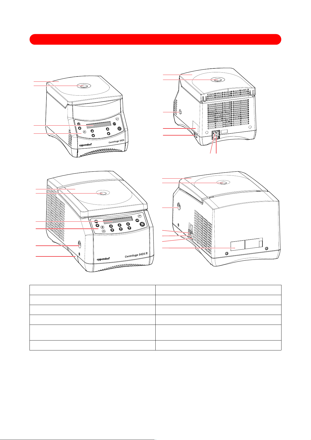
Abb. 1: Front and rear view of the Ce ntrifuge 5424
Fig. 1: Front and rear view of the Centrifuge 5424
Abb. 2: Front and rear view of the Ce ntrifuge 5424 R
Fig. 2: Front and rear view of the Centrifuge 5424 R
1 Centrifuge lid 2 Window
3 Display 4 Control panel
5 Emergency release 6 ID plate
7 Mains switch 8 Power connection
9 Fuse holder 10 USB port
(only 5424 R, only for technical support)
11 Condensation water tray (only 5424 R)
Page 4

Abb. 3: Control panel of the Centr ifuge 5424 / 5424 R
Fig. 3: Control panel of the Centrifuge 5424 / 5424 R
1 Call and select the menu parameters 2 Switch the centrifuging speed displayed (rpm/rcf)
3 Display 4 Short Spin centrifugation
5 Release lid 6 Start and stop centrifugation
7 Set the speed of centrifugation
8 Adjust the temperature (only 5424 R)
Dependent on device version designed as a key or
dial.
9 Adjust the centrifuging duration
Dependent on device version designed as a key or
10 Start the temperature control run fast temp
(only 5424 R)
dial.
11 Select the menu item
Abb. 4: Display of the Centrifug e 5424 / 5424 R
Fig. 4: Display of the Centrifuge 5424 R. The display of the Centrifuge 5424 is similar.
1 Centrifuging duration 2 Status of the key lock (LOCK)
3 Status of the function ATSET 4 Temperature (only 5424 R)
5 Soft ramp 6 g-force (rcf) or speed (rpm)
7 Status of the centrifuge 8 Status of the centrifugation speed display
9 Status of the loudspeaker
Page 5

Centrifuge 5424 / 5424 R — Operating manual
Table of contents
Operating manual
Table of contents
1 User instructions . . . . . . . . . . . . . . . . . . . . . . . . . . . . . . . . . . . . . . . . . . . . . . . . . . . . . . . . . . . . . . . . . . . . . . . . . . . . 7
1.1 Using this manual . . . . . . . . . . . . . . . . . . . . . . . . . . . . . . . . . . . . . . . . . . . . . . . . . . . . . . . . . . . . . . . . . . . . . . . 7
1.2 Warning signs and hazard icons. . . . . . . . . . . . . . . . . . . . . . . . . . . . . . . . . . . . . . . . . . . . . . . . . . . . . . . . . . . . 7
1.2.1 Hazard symbols . . . . . . . . . . . . . . . . . . . . . . . . . . . . . . . . . . . . . . . . . . . . . . . . . . . . . . . . . . . . . . . . . 7
1.2.2 Degrees of danger . . . . . . . . . . . . . . . . . . . . . . . . . . . . . . . . . . . . . . . . . . . . . . . . . . . . . . . . . . . . . . . 7
1.3 Abbreviations used. . . . . . . . . . . . . . . . . . . . . . . . . . . . . . . . . . . . . . . . . . . . . . . . . . . . . . . . . . . . . . . . . . . . . . 7
2 Product description. . . . . . . . . . . . . . . . . . . . . . . . . . . . . . . . . . . . . . . . . . . . . . . . . . . . . . . . . . . . . . . . . . . . . . . . . . 8
2.1 Main illustration. . . . . . . . . . . . . . . . . . . . . . . . . . . . . . . . . . . . . . . . . . . . . . . . . . . . . . . . . . . . . . . . . . . . . . . . . 8
2.2 Delivery package . . . . . . . . . . . . . . . . . . . . . . . . . . . . . . . . . . . . . . . . . . . . . . . . . . . . . . . . . . . . . . . . . . . . . . . 9
2.2.1 Centrifuge 5424 . . . . . . . . . . . . . . . . . . . . . . . . . . . . . . . . . . . . . . . . . . . . . . . . . . . . . . . . . . . . . . . . . 9
2.2.2 Centrifuge 5424 R. . . . . . . . . . . . . . . . . . . . . . . . . . . . . . . . . . . . . . . . . . . . . . . . . . . . . . . . . . . . . . . . 9
2.3 Features . . . . . . . . . . . . . . . . . . . . . . . . . . . . . . . . . . . . . . . . . . . . . . . . . . . . . . . . . . . . . . . . . . . . . . . . . . . . . . 9
2.4 Rotors. . . . . . . . . . . . . . . . . . . . . . . . . . . . . . . . . . . . . . . . . . . . . . . . . . . . . . . . . . . . . . . . . . . . . . . . . . . . . . . 10
2.4.1 Rcf display and calculation . . . . . . . . . . . . . . . . . . . . . . . . . . . . . . . . . . . . . . . . . . . . . . . . . . . . . . . . 11
3 Safety . . . . . . . . . . . . . . . . . . . . . . . . . . . . . . . . . . . . . . . . . . . . . . . . . . . . . . . . . . . . . . . . . . . . . . . . . . . . . . . . . . . . 12
3.1 Intended use. . . . . . . . . . . . . . . . . . . . . . . . . . . . . . . . . . . . . . . . . . . . . . . . . . . . . . . . . . . . . . . . . . . . . . . . . . 12
3.2 User profile . . . . . . . . . . . . . . . . . . . . . . . . . . . . . . . . . . . . . . . . . . . . . . . . . . . . . . . . . . . . . . . . . . . . . . . . . . . 12
3.3 Application limits. . . . . . . . . . . . . . . . . . . . . . . . . . . . . . . . . . . . . . . . . . . . . . . . . . . . . . . . . . . . . . . . . . . . . . . 12
3.3.1 Declaration concerning the ATEX directive (94/9/EC). . . . . . . . . . . . . . . . . . . . . . . . . . . . . . . . . . . . 12
3.3.2 Maximum service life for accessories . . . . . . . . . . . . . . . . . . . . . . . . . . . . . . . . . . . . . . . . . . . . . . . . 12
3.4 Information on product liability . . . . . . . . . . . . . . . . . . . . . . . . . . . . . . . . . . . . . . . . . . . . . . . . . . . . . . . . . . . . 13
3.5 Warnings for intended use . . . . . . . . . . . . . . . . . . . . . . . . . . . . . . . . . . . . . . . . . . . . . . . . . . . . . . . . . . . . . . . 13
3.5.1 Personal injury or damage to the equipment . . . . . . . . . . . . . . . . . . . . . . . . . . . . . . . . . . . . . . . . . . 13
3.5.2 Incorrect handling of the centrifuge. . . . . . . . . . . . . . . . . . . . . . . . . . . . . . . . . . . . . . . . . . . . . . . . . . 14
3.5.3 Incorrect handling of the rotors . . . . . . . . . . . . . . . . . . . . . . . . . . . . . . . . . . . . . . . . . . . . . . . . . . . . . 14
3.5.4 Extreme strain on the centrifuging tubes. . . . . . . . . . . . . . . . . . . . . . . . . . . . . . . . . . . . . . . . . . . . . . 15
3.5.5 Aerosol-tight centrifugation . . . . . . . . . . . . . . . . . . . . . . . . . . . . . . . . . . . . . . . . . . . . . . . . . . . . . . . . 16
3.6 Safety instructions on the device . . . . . . . . . . . . . . . . . . . . . . . . . . . . . . . . . . . . . . . . . . . . . . . . . . . . . . . . . . 16
4 Installation . . . . . . . . . . . . . . . . . . . . . . . . . . . . . . . . . . . . . . . . . . . . . . . . . . . . . . . . . . . . . . . . . . . . . . . . . . . . . . . . 17
4.1 Selecting the location . . . . . . . . . . . . . . . . . . . . . . . . . . . . . . . . . . . . . . . . . . . . . . . . . . . . . . . . . . . . . . . . . . . 17
4.2 Installing the instrument . . . . . . . . . . . . . . . . . . . . . . . . . . . . . . . . . . . . . . . . . . . . . . . . . . . . . . . . . . . . . . . . . 17
5 Operation . . . . . . . . . . . . . . . . . . . . . . . . . . . . . . . . . . . . . . . . . . . . . . . . . . . . . . . . . . . . . . . . . . . . . . . . . . . . . . . . . 18
5.1 Overview of operating controls. . . . . . . . . . . . . . . . . . . . . . . . . . . . . . . . . . . . . . . . . . . . . . . . . . . . . . . . . . . . 18
5.2 Device menu. . . . . . . . . . . . . . . . . . . . . . . . . . . . . . . . . . . . . . . . . . . . . . . . . . . . . . . . . . . . . . . . . . . . . . . . . . 20
5.3 Menu navigation . . . . . . . . . . . . . . . . . . . . . . . . . . . . . . . . . . . . . . . . . . . . . . . . . . . . . . . . . . . . . . . . . . . . . . . 21
5.4 Preparing for centrifugation . . . . . . . . . . . . . . . . . . . . . . . . . . . . . . . . . . . . . . . . . . . . . . . . . . . . . . . . . . . . . . 21
5.4.1 Switch on centrifuge . . . . . . . . . . . . . . . . . . . . . . . . . . . . . . . . . . . . . . . . . . . . . . . . . . . . . . . . . . . . . 21
5.4.2 Inserting the rotor . . . . . . . . . . . . . . . . . . . . . . . . . . . . . . . . . . . . . . . . . . . . . . . . . . . . . . . . . . . . . . . 21
5.4.3 Load the rotor . . . . . . . . . . . . . . . . . . . . . . . . . . . . . . . . . . . . . . . . . . . . . . . . . . . . . . . . . . . . . . . . . . 21
5.4.4 Close centrifuge lid . . . . . . . . . . . . . . . . . . . . . . . . . . . . . . . . . . . . . . . . . . . . . . . . . . . . . . . . . . . . . . 23
5.5 Cooling (only 5424 R). . . . . . . . . . . . . . . . . . . . . . . . . . . . . . . . . . . . . . . . . . . . . . . . . . . . . . . . . . . . . . . . . . . 23
5.5.1 Temperature adjustment . . . . . . . . . . . . . . . . . . . . . . . . . . . . . . . . . . . . . . . . . . . . . . . . . . . . . . . . . . 23
5.5.2 Temperature display . . . . . . . . . . . . . . . . . . . . . . . . . . . . . . . . . . . . . . . . . . . . . . . . . . . . . . . . . . . . . 23
5.5.3 Temperature monitoring . . . . . . . . . . . . . . . . . . . . . . . . . . . . . . . . . . . . . . . . . . . . . . . . . . . . . . . . . . 23
5.5.4 Fast Temp . . . . . . . . . . . . . . . . . . . . . . . . . . . . . . . . . . . . . . . . . . . . . . . . . . . . . . . . . . . . . . . . . . . . . 23
5.5.5 Continuous cooling . . . . . . . . . . . . . . . . . . . . . . . . . . . . . . . . . . . . . . . . . . . . . . . . . . . . . . . . . . . . . . 24
5.6 Centrifuging . . . . . . . . . . . . . . . . . . . . . . . . . . . . . . . . . . . . . . . . . . . . . . . . . . . . . . . . . . . . . . . . . . . . . . . . . . 24
5.6.1 Centrifuging with time preset. . . . . . . . . . . . . . . . . . . . . . . . . . . . . . . . . . . . . . . . . . . . . . .
5.6.
2 Centrifuging in continuous operation . . . . . . . . . . . . . . . . . . . . . . . . . . . . . . . . . . . . . . . . . . . . . . . . 25
5.6.3 Short spin centrifugation . . . . . . . . . . . . . . . . . . . . . . . . . . . . . . . . . . . . . . . . . . . . . . . . . . . . . . . . . . 26
5.6.4 Removing the rotor . . . . . . . . . . . . . . . . . . . . . . . . . . . . . . . . . . . . . . . . . . . . . . . . . . . . . . . . . . . . . . 26
Operating manual — Centrifuge 5424 / 5424 Rseeon p.Fig.Tab.p.
. . . . . . . . 25
EN
Operating manual
5
Page 6

EN
Operating manual
Centrifuge 5424 / 5424 R — Operating manual
Table of contents
6 Maintenance . . . . . . . . . . . . . . . . . . . . . . . . . . . . . . . . . . . . . . . . . . . . . . . . . . . . . . . . . . . . . . . . . . . . . . . . . . . . . . . 27
6.1 Prepare cleaning / disinfection . . . . . . . . . . . . . . . . . . . . . . . . . . . . . . . . . . . . . . . . . . . . . . . . . . . . . . . . . . . . 27
6.2 Perform cleaning / disinfection . . . . . . . . . . . . . . . . . . . . . . . . . . . . . . . . . . . . . . . . . . . . . . . . . . . . . . . . . . . . 27
6.2.1 Clean / disinfect device. . . . . . . . . . . . . . . . . . . . . . . . . . . . . . . . . . . . . . . . . . . . . . . . . . . . . . . . . . . 28
6.2.2 Clean / disinfect rotor . . . . . . . . . . . . . . . . . . . . . . . . . . . . . . . . . . . . . . . . . . . . . . . . . . . . . . . . . . . . 28
6.3 Additional service instructions for Centrifuge 5424 R. . . . . . . . . . . . . . . . . . . . . . . . . . . . . . . . . . . . . . . . . . . 29
6.4 Glass breakage. . . . . . . . . . . . . . . . . . . . . . . . . . . . . . . . . . . . . . . . . . . . . . . . . . . . . . . . . . . . . . . . . . . . . . . . 29
6.5 Fuses . . . . . . . . . . . . . . . . . . . . . . . . . . . . . . . . . . . . . . . . . . . . . . . . . . . . . . . . . . . . . . . . . . . . . . . . . . . . . . . 29
6.6 Decontamination before shipping . . . . . . . . . . . . . . . . . . . . . . . . . . . . . . . . . . . . . . . . . . . . . . . . . . . . . . . . . . 29
7 Troubleshooting. . . . . . . . . . . . . . . . . . . . . . . . . . . . . . . . . . . . . . . . . . . . . . . . . . . . . . . . . . . . . . . . . . . . . . . . . . . . 30
7.1 General errors . . . . . . . . . . . . . . . . . . . . . . . . . . . . . . . . . . . . . . . . . . . . . . . . . . . . . . . . . . . . . . . . . . . . . . . . 30
7.2 Error messages . . . . . . . . . . . . . . . . . . . . . . . . . . . . . . . . . . . . . . . . . . . . . . . . . . . . . . . . . . . . . . . . . . . . . . . 31
7.3 Emergency release. . . . . . . . . . . . . . . . . . . . . . . . . . . . . . . . . . . . . . . . . . . . . . . . . . . . . . . . . . . . . . . . . . . . . 32
8 Transport, storage and disposal . . . . . . . . . . . . . . . . . . . . . . . . . . . . . . . . . . . . . . . . . . . . . . . . . . . . . . . . . . . . . . 33
8.1 Transport . . . . . . . . . . . . . . . . . . . . . . . . . . . . . . . . . . . . . . . . . . . . . . . . . . . . . . . . . . . . . . . . . . . . . . . . . . . . 33
8.2 Storage. . . . . . . . . . . . . . . . . . . . . . . . . . . . . . . . . . . . . . . . . . . . . . . . . . . . . . . . . . . . . . . . . . . . . . . . . . . . . . 33
8.3 Disposal . . . . . . . . . . . . . . . . . . . . . . . . . . . . . . . . . . . . . . . . . . . . . . . . . . . . . . . . . . . . . . . . . . . . . . . . . . . . . 33
9 Technical data . . . . . . . . . . . . . . . . . . . . . . . . . . . . . . . . . . . . . . . . . . . . . . . . . . . . . . . . . . . . . . . . . . . . . . . . . . . . . 34
9.1 Power supply . . . . . . . . . . . . . . . . . . . . . . . . . . . . . . . . . . . . . . . . . . . . . . . . . . . . . . . . . . . . . . . . . . . . . . . . . 34
9.2 Ambient conditions . . . . . . . . . . . . . . . . . . . . . . . . . . . . . . . . . . . . . . . . . . . . . . . . . . . . . . . . . . . . . . . . . . . . . 34
9.3 Weight / dimensions . . . . . . . . . . . . . . . . . . . . . . . . . . . . . . . . . . . . . . . . . . . . . . . . . . . . . . . . . . . . . . . . . . . . 35
9.4 Application parameters. . . . . . . . . . . . . . . . . . . . . . . . . . . . . . . . . . . . . . . . . . . . . . . . . . . . . . . . . . . . . . . . . . 35
9.4.1 Centrifuge 5424 . . . . . . . . . . . . . . . . . . . . . . . . . . . . . . . . . . . . . . . . . . . . . . . . . . . . . . . . . . . . . . . . 35
9.4.2 Centrifuge 5424 R. . . . . . . . . . . . . . . . . . . . . . . . . . . . . . . . . . . . . . . . . . . . . . . . . . . . . . . . . . . . . . . 36
10 Ordering information. . . . . . . . . . . . . . . . . . . . . . . . . . . . . . . . . . . . . . . . . . . . . . . . . . . . . . . . . . . . . . . . . . . . . . . . 37
10.1 Centrifuge 5424 . . . . . . . . . . . . . . . . . . . . . . . . . . . . . . . . . . . . . . . . . . . . . . . . . . . . . . . . . . . . . . . . . . . . . . . 37
10.2 Centrifuge 5424 R . . . . . . . . . . . . . . . . . . . . . . . . . . . . . . . . . . . . . . . . . . . . . . . . . . . . . . . . . . . . . . . . . . . . . 37
10.3 Accessories . . . . . . . . . . . . . . . . . . . . . . . . . . . . . . . . . . . . . . . . . . . . . . . . . . . . . . . . . . . . . . . . . . . . . . . . . . 38
10.3.1 Rotors and rotor lids . . . . . . . . . . . . . . . . . . . . . . . . . . . . . . . . . . . . . . . . . . . . . . . . . . . . . . . . . . . . . 38
10.3.2 Adapters . . . . . . . . . . . . . . . . . . . . . . . . . . . . . . . . . . . . . . . . . . . . . . . . . . . . . . . . . . . . . . . . . . . . . . 38
10.3.3 Other accessories. . . . . . . . . . . . . . . . . . . . . . . . . . . . . . . . . . . . . . . . . . . . . . . . . . . . . . . . . . . . . . . 38
10.4 Fuses . . . . . . . . . . . . . . . . . . . . . . . . . . . . . . . . . . . . . . . . . . . . . . . . . . . . . . . . . . . . . . . . . . . . . . . . . . . . . . . 38
6
Page 7
Centrifuge 5424 / 5424 R — Operating manual
1 User instructions
1 User instructions
1.1 Using this manual
1.2 Warning signs and hazard icons
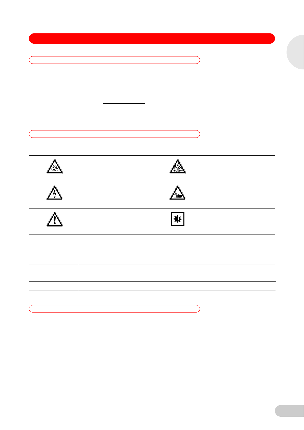
1.2.1 Hazard symbols
Operating manual — Centrifuge 5424 / 5424 Rseeon p.Fig.Tab.p.
Please read this operating manual completely before using the device for the first time.
Please view this operating manual as part of the product and keep it somewhere easily
accessible.
When passing the device on to third parties, be sure to include this operating manual.
If this manual is lost, please request another one. The current version can be found on our
website www.eppendorf.com.
The Centrifuge 5424 / 5424 R is available in two versions: keypad or rotary knobs. This
operating manual generally describes how to operate the keypad version. However, it also
applies to the rotary knob version.
Biohazard Explosion
EN
Operating manual
Electric shock Crushing
Hazard point Material damage
1.2.2 Degrees of danger
The degree of danger is a part of a safety note and distinguishes the possible results of
non-observance from each other.
DANGER Will lead to severe injuries or death.
WARNING May lead to severe injuries or death.
CAUTION May lead to light to moderate injuries.
NOTICE May lead to material damage.
1.3 Abbreviations used
PCR Polymerase chain reaction
PTFE Polytetrafluorethylen
rcf Relative centrifugal force
rpm Revolutions per
UV Ultraviolet radiation
minute
7
Page 8
1
3
4
2
1
5
6
7
2
8
9
1
3
4
10
11
2
1
5
7
6
9
8
2
EN
Operating manual
Centrifuge 5424 / 5424 R — Operating manual
2 Product description
2 Product description
2.1 Main illustration
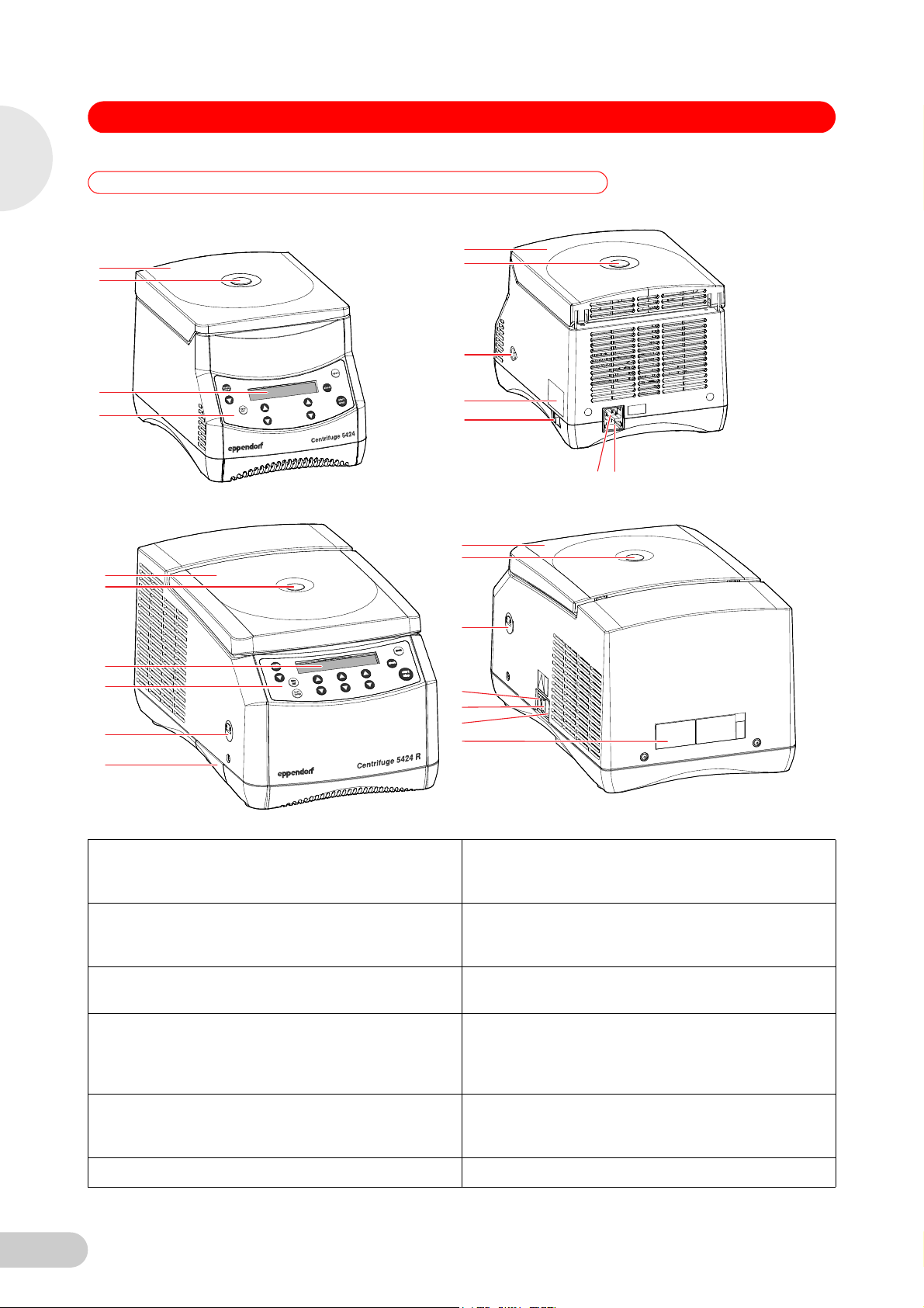
The depiction of the Centrifuge 5424 / 5424 R can also be found on the front fold-out page (see Fig. 1 and Fig. 2).
Abb. 1: Front and rear view of the Ce ntrifuge 5424
Operating manual — Centrifuge 5424 / 5424 Rseeon p.Fig.Tab.p.
Fig. 1: Front and rear view of the Centrifuge 5424
Abb. 2: Front and rear view of the Ce ntrifuge 5424 R
Fig. 2: Front and rear view of the Centrifuge 5424 R
1 Centrifuge lid 2 Monitoring glass
Visual control for rotor stop or option for speed control
via stroboscope.
3Display
Depiction of the current centrifuging parameters and
device settings (see Fig. 4 on p. 19).
4 Control panel
Keys and dials (dependent on the device version) for
operating the centrifuge (see Fig. 3 on p. 18).
5 Emergency lid release
6ID plate
(see Emergency release on p. 32)
7 Mains switch
Switch for switching the device on and off.
Switch position 0: The device is switched off.
Switch position I: The device is switched on.
8 Mains connection
Connection socket for the mains cable supplied.
9 Fuse holder 10 USB port (only 5424 R)
Interface for error analysis and software updates by
the Technical Service.
11 Condensation water tray (only 5424 R)
8
Page 9

Centrifuge 5424 / 5424 R — Operating manual
2 Product description
2.2 Delivery package
EN
2.2.1 Centrifuge 5424
Quantity Order No.
(International)
1- -
1
or
1 5416 301.001 022634305
1 5703 350.102 022639609
1- - Power cable
1
1
2.2.2 Centrifuge 5424 R
Quantity Order No.
1- -
1
or
1 5416 301.001 022634305
1- - Power cable
1 5404 850.085 5404850085 Tray for condensation water
1
1
5424 852.122
5424 852.130
5404 900.023
5404 900.031
(International)
5424 852.122
5424 852.130
5404 900.023
5404 900.031
Order No.
(North America)
950004266
950004240
5404900023
5404900031
Order No.
(North America)
950004266
950004240
5404900023
5404900031
Description
Centrifuge 5424
See chapter Ordering Information for corresponding device version,
equipment and order number
Fuses
3.15 AT for 230 V, 2 pieces
6.3 AT for 120 V/100 V, 2 pieces
Rotor key
Standard
Captain Eppi rotor key holder
1 piece
Operating manual Centrifuge 5424/5424 R
Languages: EN, DE, FR, ES, IT, PT
Languages: DA, FI, EL, NL, SV (230 V devices only)
Description
Centrifuge 5424 R
See chapter Ordering Information for corresponding device version,
equipment and order number
Fuses
3.15 AT for 230 V, 2 pieces
6.3 AT for 120 V/100 V, 2 pieces
Rotor key
Standard
Operating manual Centrifuge 5424/5424 R
Languages: EN, DE, FR, ES, IT, PT
Languages: DA, FI, EL, NL, SV (230 V devices only)
Operating manual
2.3 Features
The versatile Centrifuge 5424 / 5424 R has a capacity of 24 x 2 mL and reaches a maximum of
21,130 x g / 15,000 rpm (5424: 120 V, 5424 R: 230 V, 120 V, 100 V) or 20,238 x g / 14,680 rpm
(5424: 230 V, 100 V). You can select between four different rotors to centrifuge the following
tubes for your various applications:
• Micro test tubes (0.2 to 2.0 mL)
• PCR strips
• Microtainers (0.6 mL)
• Spin columns (1.5/2.0 mL)
The Centrifuge 5424 R has an additional temperature control function for centrifugation between
-10°C and +40°C. The fast temp function can be used to start a temperature control run without
samples to adjust the rotor chamber quickly to the set target temperature.
9
Page 10

EN
Centrifuge 5424 / 5424 R — Operating manual
2 Product description
2.4 Rotors
You can operate the Centrifuge 5424 / 5424 R with the following rotors. Before use of sample
tubes, please note the manufacturer's specifications with regard to centrifugation resistance
(max. rcf).
Operating manual
Rotor
FA-45-24-11
Rotor
FA-45-24-11-
Special
Rotor
F-45-18-11-
Kit
Rotor
F-45-32-5-
PCR
Max. capacity Max. g-force (rcf) /
speed (rpm)
without adapter
(5424: 120 V,
5424 R)
Max. load per rotor bore
24 micro test tubes of 1.5/2.0 mL
each or spin columns.
With adapters:
• 0.2 mL PCR tubes
21,130 x g /
15,000 rpm
3.75 g
• 0.4 mL/0.5 mL micro test
tubes
• 0.6 mL Microtainers
24 micro test tubes of 1.5/2.0 mL
each or spin columns.
With adapters:
• 0.2 mL PCR tubes
21,130 x g /
15,000 rpm
3.75 g
• 0.4 mL/0.5 mL micro test
tubes
• 0.6 mL Microtainers
18 spin columns or 1.5/2.0 mL
micro test tubes.
With adapters:
18,111 x g /
15,000 rpm
3.75 g
• 0.2 mL PCR tubes
• 0.4 mL/0.5 mL micro test
tubes
• 0.6 mL Microtainers
Four PCR strips of 5/8 or
32 PCR tubes of 0.2 mL each.
18,615 x g /
15,000 rpm
3.5 g
Max. g-force (rcf) or
speed (rpm)
without adapter
(5424: 230 V/100 V)
(1)
20,238 x g /
14,860 rpm
20,238 x g /
14,860 rpm
17,347 x g /
14,860 rpm
17,829 x g /
14,860 rpm
Notes
• Aerosol-tight
lid (aluminum).
(2)
rotor
• Spin columns
possible, better with
rotor F-45-18-11-Kit.
• Aerosol-tight
lid (aluminum).
(2)
rotor
• PTFE-coated
(particularly resistant
to chemicals),
marked: coated
• Spin columns
possible, better with
rotor F-45-18-11-Kit.
• Particularly high edge
for all commercially
available spin
columns. See the note
about centrifugation
with open tube lids in
this regard(see Load
the rotor on p. 21).
10
(1) Maximum load per rotor bore for adapter + tube + content.
(2) Aerosol tightness tested and certified by the Centre for Emergency Preparedness and
Response, Health Protection Agency, Porton Down (UK) (see certificates at the end of this
operating manual).
For the rotors and rotor lids labeled coated, color fluctuations may occur as a result of the
production process. These fluctuations have no effect on service life or resistance to chemicals.
Page 11

Centrifuge 5424 / 5424 R — Operating manual
2 Product description
2.4.1 Rcf display and calculation
Use the rpm/rcf key to switch the display of centrifugation speed between speed (rpm) and
g-force (rcf). Ensure that the g-force displayed upon switching is standardized to suit the rotor
FA-45-24-11 without an adapter. When other rotors and adapters are used, you can achieve the
following maximum g-forces (rcf) at the maximum speed (see p. 10):
EN
Operating manual
Rotor Adapters Max. centrifugation
radius r
FA-45-24-11,
FA-45-24-11-Special
F-45-18-11-Kit without adapter 7.2 18,111 17,347
FA-45-32-5-PCR without adapter 7.4 18,615 17,829
without adapter 8.4 21,130 20,238
0.2 mL 6.3 15,848 15,179
0.4 mL 8.4 21,130 20,238
0.5 mL 7.3 18,363 17,558
0.6 mL 8.4 21,130 20,238
0.2 mL 5.1 12,829 12,288
0.4 mL 7.2 18,111 17,347
0.5 mL 6.1 15,345 14,697
0.6 mL 7.2 18,111 17,347
To determine the g-force (rcf) for a specific adapter, you can calculate per DIN 58 970 using the
following formula:
rcf = 1.118 · 10-5 · n2 · r
n: revolutions per minute (rpm)
r
: max. centrifuging radius in cm
max
Example
In rotor FA-45-24-11, the 0.5 mL adapter has a maximum radius of 7.3 cm. At 7,000 rpm a
maximum g-force of 4,000 x g is reached.
max
max
[cm]
Max. g-force (rcf)
(5424 120 V, 5424 R)
Max. g-force (rcf)
(5424 230 V/100 V)
11
Page 12
EN
Operating manual
3 Safety
3Safety
3.1 Intended use
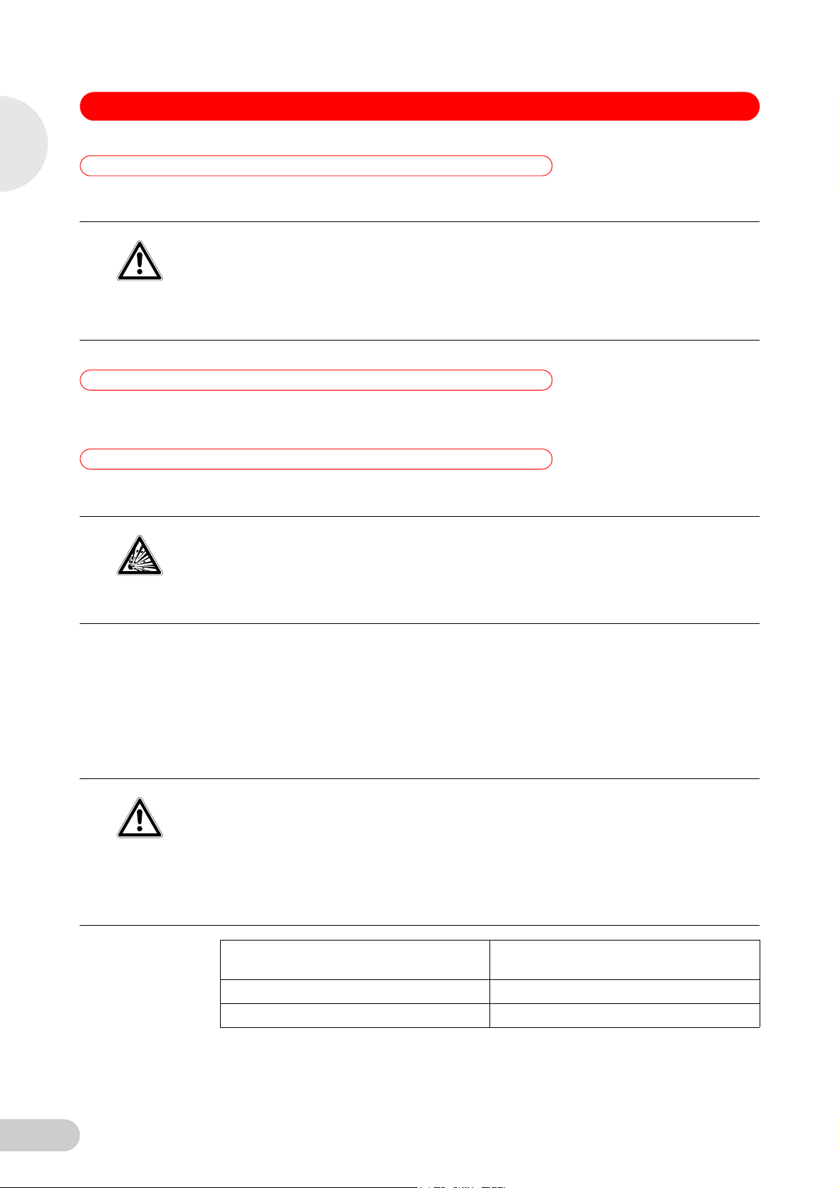
CAUTION!
3.2 User profile
Centrifuge 5424 / 5424 R — Operating manual
Operating manual — Centrifuge 5424 / 5424 Rseeon p.Fig.Tab.p.
The Centrifuge 5424 / 5424 R is intended exclusively for indoor use and for separating aqueous
solutions and suspensions of various densities in approved test tubes.
Poor safety due to incorrect accessories and spare parts.
The use of accessories and spare parts other than those recommended by Eppendorf may
impair the safety, functioning and precision of the device. Eppendorf cannot be held liable for any
damage resulting from the use of non-recommended accessories and spare parts or from the
improper use of such equipment.
Only use accessories and original spare parts recommended by Eppendorf.
This device may only be operated by correspondingly trained specialist staff. This staff must have
carefully read the operating manual and be familiar with the function of the device.
3.3 Application limits
3.3.1 Declaration concerning the ATEX directive (94/9/EC)
Danger of explosion!
Do not operate the device in areas where work is being carried out with explosive substances.
Do not use this device to process any explosive, radioactive or highly reactive substances.
DANGER!
3.3.2 Maximum service life for accessories
Do not use this device to process any substances which could create an explosive
atmosphere.
Due to its design and the environmental conditions on the inside of the device, the Centrifuge
5424 / 5424 R is not suitable for use in a potentially explosive atmosphere.
The device must therefore only be used in a safe environment, such as in the open environment
of a ventilated laboratory or an extractor hood. The use of substances which may contribute to a
potentially explosive atmosphere is not permitted. The final decision with regard to the risks
connected with the use of such substances is the responsibility of the user.
Risk of injury from chemically or mechanically damaged accessories.
Even small scratches and cracks can lead to serious internal material damage.
Protect all parts from mechanical damage.
CAUTION!
Check accessories regularly.
Do not use rotors or buckets with signs of corrosion or mechanical damage (e.g.
deformations).
Do not use accessories whose maximum service life has been exceeded.
12
Accessory Maximum service life from first
commissioning
Transparent polypropylene rotor lids 3 years
Plastic adapters 1 year
Page 13
Centrifuge 5424 / 5424 R — Operating manual
3 Safety
For the other rotors and rotor lids of this centrifuge (see Rotors on p. 10) there is no limit for their
service life, as long as the following conditions are met: proper use, recommended maintenance
and undamaged condition. Lids of aerosol-tight rotors must be replaced after 50 autoclave cycles
to ensure aerosol tightness.
The date of manufacture is stamped on the rotors in the format 03/07 (= March 2007) or on the
inside of the plastic rotor lids in the form of a clock . This is for information only and does not
have any reference to the service life.
3.4 Information on product liability
In the following cases, the protection provided by the device may be impaired. The liability for the
function of the device passes to the operator if:
• The device is not used in accordance with the operating manual.
• The device is used outside of the range of application described in the preceding chapters.
• The device is used with accessories or consumables (e.g., tubes) which are not
recommended by Eppendorf.
• The device is maintained or repaired by persons not authorized by Eppendorf.
• The owner has made unauthorized modifications to the device.
EN
Operating manual
3.5 Warnings for intended use
Read the operating manual first and observe the following general safety instructions before
using the Centrifuge 5424 / 5424 R.
3.5.1 Personal injury or damage to the equipment
Risk of electrical shock from damage to the device or mains cable.
The device may only be switched on if the device and mains cable are undamaged.
Only use devices which have been professionally installed or repaired.
WARNING!
Lethal voltages inside the device.
Ensure that the housing is always closed and undamaged so that no parts inside the device
can be contacted by accident.
WARNING!
WARNING!
Do not remove the housing of the device.
Do not allow any liquids to enter the inside of the housing.
Do not allow the device to be opened by anyone except service personnel who have been
specifically authorized by Eppendorf.
Danger from using an incorrect power supply.
Only connect the device to voltage supplies which correspond with the electrical requirements
on the name plate.
13
Page 14

EN
Operating manual
3 Safety
WARNING!
WARNING!
Centrifuge 5424 / 5424 R — Operating manual
Damage to health when handling infectious liquids and pathogenic germs.
Observe the national regulations for handling these substances, the biological security level
of your laboratory, the material safety data sheets and the manufacturer's application notes.
Use suitable aerosol-tight closure systems for the centrifugation of these substances.
When working with pathogenic germs belonging to a higher risk group, more than one
aerosol-tight bioseal must be provided for.
Wear personal protective equipment (PPE).
Follow the instructions regarding hygiene, cleaning and decontamination.
For complete instructions regarding the handling of germs or biological material of risk group
II or higher, please refer to the "Laboratory Biosafety Manual" (Source: World Health
Organization, current edition of the Laboratory Biosafety Manual).
Centrifuge lid can crush. Keep hands clear.
When opening or closing the device lid, do not reach between the lid and device or into the
latching mechanism of the lid.
Always open the centrifuge lid completely to prevent it from falling.
Damage to device by spilling liquids in the rotor or rotor chamber
1. Switch the device off.
2. Disconnect the device from the power supply.
NOTICE!
NOTICE!
3. Clean the device and the accessories carefully in accordance with the cleaning and
disinfection instructions in the operating manual.
4. If a different cleaning and disinfecting method is to be used, contact Eppendorf to ensure that
the intended method will not damage the device.
Damage to electronic components through formation of condensation.
After the device has been moved from a cool to a warmer environment, condensation can form
inside the device.
Wait at least three hours (5424) or four hours (5424 R) before connecting the device to the
power supply.
Only 5424: Alternatively: let the device run for half an hour before transporting it.
3.5.2 Incorrect handling of the centrifuge
Damage from knocking against or moving the device during operation.
A rotor banging against the rotor chamber wall can cause considerable damage to the device and
rotor.
NOTICE!
Do not move or knock against the device during operation.
3.5.3 Incorrect handling of the rotors
Risk of injury from improperly attached rotors and rotor lids.
Centrifuge only with the rotor and rotor lid firmly tightened.
If unusual noises occur when the centrifuge starts, the rotor or the rotor lid may not be
CAUTION!
14
properly secured. Stop centrifugation immediately by pressing the start/stop key.
Page 15

3 Safety
CAUTION!
CAUTION!
NOTICE!
Centrifuge 5424 / 5424 R — Operating manual
Risk of injury from asymmetric loading of rotors.
Load rotors symmetrically with identical tubes.
Only load adapters with suitable tubes.
Always use tubes of the same type (weight, material/density and volume).
Check symmetric loading by balancing the adapters and tubes used with scales.
Risk of injury from overloaded rotor.
The Centrifuge 5424 / 5424 R is designed for the centrifugation of material with a max. density of
1.2 g/mL at maximum speed and volume and/or load.
Observe the information on each rotor relating to maximum load (adapter, tube and contents)
per rotor bore and make sure it is not exceeded.
Damage to rotors from aggressive chemicals.
Rotors are high-quality components which withstand extreme stresses. This stability can be
impaired by aggressive chemicals.
Avoid the use of aggressive chemicals, including strong and weak alkali, strong acids,
solutions with mercury, copper and other heavy metal ions, halogenated hydrocarbons,
concentrated saline solutions and phenol.
If the rotor is contaminated by aggressive chemicals, clean it immediately using a neutral
cleaning agent. This applies to the rotor bores in particular.
EN
Operating manual
3.5.4 Extreme strain on the centrifuging tubes
Risk of injury from overloaded tubes.
Note the loading limits specified by the tube manufacturer.
Only use tubes which are approved by the manufacturer for the required rcf.
CAUTION!
Risk from damaged tubes.
Damaged tubes must not be used, as this could cause further damage to the device and the
accessories and loss of the samples.
NOTICE!
NOTICE!
NOTICE!
Before use, carry out a visual check of all tubes for any damage.
Risk from open tube lids.
Open tube lids can break off during centrifugation and cause damage to the rotor as well as to
the centrifuge.
Carefully close all tube lids before centrifuging.
Exception: Note the information on the centrifugation of spin columns in the rotor F-45-18-11-Kit
(see Load the rotor on p. 21).
Hazard to plastic tubes from organic solvents.
When using organic solvents (e.g. phenol, chloroform) the density of plastic tubes is reduced,
i.e., the tubes could get damaged.
Follow the manufacturer's information about the chemical resistance of tubes.
15
Page 16

EN
Centrifuge 5424 / 5424 R — Operating manual
3 Safety
Sample tubes heat up.
In uncooled centrifuges the temperature in the rotor chamber, rotor and sample can rise to above
40°C dependent on the run time, g-force (rcf) or speed (rpm) and ambient temperature.
NOTICE!
3.5.5 Aerosol-tight centrifugation
Note that this can reduce the centrifugation resistance of the sample tubes.
Please note the temperature resistance of the samples.
Operating manual
Risk to health due to limited aerosol tightness with incorrect rotor/rotor lid combination.
Aerosol-tight centrifugation is guaranteed only if the rotors and rotor lids intended for this purpose
are used. These are always indicated by the prefix FA.
WARNING!
WARNING!
3.6 Safety instructions on the device
Depiction Meaning Location
Always use rotors and rotor lids marked aerosol-tight together for aerosol-tight centrifugation.
Only use aerosol-tight rotor lids in combination with rotors which are marked on the rotor lid.
Risk to health due to limited aerosol tightness in the event of incorrect use.
Autoclaving, mechanical stresses and contamination by chemicals or other aggressive solvents
can impair the aerosol-tightness of the rotors and rotor lid.
Regularly check that the seals of aerosol-tight rotor lids are undamaged.
Only use aerosol-tight rotor lids with undamaged and clean gaskets.
Thinly brush the threads of the rotor lid screw with pivot grease (order no. Int.: 5810 350.050 /
North America: 022634330) after every proper autoclaving (121°C, 20 min.). Do not apply
the pivot grease to the gaskets.
Replace aerosol-tight rotor lids after 50 autoclave cycles.
Aerosol-tight rotors should never be stored with rotor lids screwed on.
WARNING
General hazard point. Follow the operating
manual.
Right side of the device
16
CAUTION
Always tighten up the rotor using the rotor key
supplied.
CAUTION
Close all tubes and use a rotor lid.
Top of device, below the centrifuge lid.
Top of device, below the centrifuge lid.
Page 17

4 Installation
4Installation
4.1 Selecting the location
Operating manual — Centrifuge 5424 / 5424 Rseeon p.Fig.Tab.p.
Centrifuge 5424 / 5424 R — Operating manual
EN
If a fault occurs, objects in the immediate vicinity of the devices could get damaged.
In accordance with the recommendations of EN 61010-2-020, leave a safety distance of 30
cm clear around the device during operation.
NOTICE!
Damage from overheating.
Do not place the device close to sources of heat (e.g., radiator, drying cabinet).
Do not expose the device to direct sunlight.
NOTICE!
Ensure free circulation of air by maintaining a distance of at least 30 cm on all sides of the
device from adjacent devices or the wall and keep the underside of the device clear.
Make sure that the vents in the device are always free of obstruction.
Select the location for the device according to the following criteria:
• Suitable power connection as per the name plate (230 V/120 V/100 V).
• Stable, horizontal and resonance-free lab bench. Weight of the device: 13.4 kg (5424) or
21 kg (5424 R).
• A well ventilated environment which is protected from direct sunlight to prevent the device
from heating up more.
4.2 Installing the instrument
Centrifuge 5424 R: Compressor damage after improper transport.
Only switch on the centrifuge 4 hours after installation.
Operating manual
NOTICE!
Hint!
Perform the following steps in the sequence described.
1. Place the device on a suitable lab bench.
2. Allow the device to warm up for at least 3 hours (5424) or 4 hours (5424 R) to the ambient
temperature to prevent damage to the electronic components from condensation and damage
to the compressor (only5424 R).
3. Check that the mains voltage and frequency match the requirements on the device type plate.
4. Connect the centrifuge to the mains and switch it on using the mains power switch on the
right side of the device.
• The display is active.
• Lid opens automatically
5. Use the details included in the scope of delivery to check that the delivery is complete.
6. Check all parts for any transport damage. Contact your dealer if any damage is found.
7. Only 5424 R: Insert the condensation water tray at the left side of the device into the holder
provided (see Fig. 2 on p. 8).
Retain the packaging material and the transport protection device for subsequent transport or
storage. See also the instructions relating to transport (see p. 33).
17
Page 18

EN
Operating manual
Centrifuge 5424 / 5424 R — Operating manual
5 Operation
5Operation
5.1 Overview of operating controls
Abb. 3: Control panel of the Centr ifuge 5424 / 5424 R
Operating manual — Centrifuge 5424 / 5424 Rseeon p.Fig.Tab.p.
The Centrifuge 5424 / 5424 R is available in two versions: keypad or rotary knobs. This operating
manual generally describes how to operate the keypad version. However, it also applies to the
rotary knob version.
Before using the Centrifuge 5424 / 5424 R for the first time, familiarize yourself with the operating
controls and the display.
The depiction of the operating controls and the display can also be found on the front fold-out
page (see Fig. 3 and Fig. 4).
Fig. 3: Control panel of the Centrifuge 5424 / 5424 R
1 Call and select the menu parameters
(see Device menu on p. 20)
3 Display 4 Short spin centrifugation
5 Release lid 6 Start and stop centrifugation
7 Set the speed of centrifugation
Dependent on device version designed as a key or
dial.
9 Adjust the centrifuging duration
Dependent on device version designed as a key or
dial.
11 Select the menu item
(see Menu navigation on p. 21)
Please also read the precise description of the individual menu functions (see p. 20).
2 Switch the displayed centrifuging speed (rpm/rcf)
(see Rcf display and calculation on p. 11)
(see Short spin centrifugation on p. 26)
8 Adjust the temperature (only 5424 R)
10 Start the temperature control run fast temp
(only 5424 R)
18
Page 19

5 Operation
Centrifuge 5424 / 5424 R — Operating manual
Abb. 4: Display of the Centrifug e 5424 / 5424 R
Fig. 4: Display of the Centrifuge 5424 R. The display of the Centrifuge 5424 is similar.
1 Centrifuging duration 2 Status of the key lock (LOCK)
: Centrifuging parameters cannot be modified
unintentionally.
: No key lock.
3 Status of the function ATSET
: Start of operation when reaching 95% of the
preset g-force (rcf) or speed (rpm).
: Start of operation immediately.
5 Soft ramp
: Rotor accelerates and brakes slowly.
No symbol: Rotor accelerates and brakes rapidly.
4 Temperature (only 5424 R)
6 g-force (rcf) or speed (rpm)
(see Rcf display and calculation on p. 11)
EN
Operating manual
7 Status of the centrifuge
: Centrifuge lid unlocked.
: Centrifuge lid locked.
(Flashing): centrifuging in progress.
5 Soft ramp
: Rotor accelerates and brakes slowly.
No symbol: Rotor accelerates and brakes rapidly.
9 Status of the loudspeaker
: Switched on
: Switched off
8 Status of the centrifugation speed display
rcf: g-force (relative centrifugal force)
rpm: revolutions per minute
6 g-force (rcf) or speed (rpm)
(see Rcf display and calculation on p. 11)
19
Page 20

EN
Centrifuge 5424 / 5424 R — Operating manual
5 Operation
5.2 Device menu
Tab. 1: Menu structure of the Centrifuge 5424 / 5424 R. All menu levels contain the additional menu item Back.
Operating manual
Level 1 (M I) Level 2
(M 2)
SOFT
Soft ramp: Reduce speed of acceleration and
braking ramp. Not used for short spin
centrifugation.
LOCK
Key lock: Set the current centrifugation
parameters permanently to prevent the time,
temperature (only 5424 R) g-force (rcf) or
speed (rpm) from being unintentionally
modified.
ATSET
Set start of centrifuging run time.
SHORT
Before the start of a short run (see Short spin
centrifugation on p. 26) it is possible to switch
between the maximum and currently set
g-force (rcf) or speed (rpm). The SOFT function
is not used for short spin centrifugation.
On Rotor accelerates and brakes slowly.
Off Rotor accelerates and brakes rapidly.
On Set the centrifugation parameters permanently.
Off
On The set time is counted down only once 95% of
Off The set time is counted down immediately.
MAX Short spin run at maximum g-force (rcf) or
Set Short run at set g-force (rcf) or speed (rpm).
Function Display
When you select the keys time, temp (only
5424 R) and speed, the display shows SAFE.
the specified g-force (rcf) or speed (rpm) has been
reached.
speed (rpm) of the rotor used.
TEMP (only 5424 R)
Set the time limitation of continuous cooling
(see p. 24).
ALARM On Switch on loudspeaker.
VOL VOL1
SLEEP
Standby mode
LID (only 5424)
Lid release, from software version 2.2.
8 h Preset value.
oo Endless operation of continuous cooling.
Icing possible! Note that this may reduce the
service life of the compressor.
Off Switch off loudspeaker.
Adjust the speaker volume in 5 steps. The loud-
...
VOL5
On If the centrifuge has not been used for 15 min and
Off Standby mode deactivated.
AUTO The centrifuge lid opens automatically after
Off The centrifuge lid must be manually opened with
speaker must be switched on for the adjustment to
be audible.
the standby mode has been switched on, it
switches to standby mode. The EP logo then
appears in the display. When a button or knob is
used or the centrifuge lid is closed, the centrifuge
is reactivated. It is then ready for operation.
centrifugation.
the open key after centrifugation.
20
Page 21

5 Operation
5.3 Menu navigation
To change settings in the device menu, proceed as follows:
1. Open the menu.
2. Select the desired menu item.
3. Confirm your selection.
4. Select the setting of the parameters in question.
Centrifuge 5424 / 5424 R — Operating manual
EN
Operating manual
5.
6. Exit the menu.
To exit the second menu level without changing a parameter, select the BACK menu item and
confirm with menu/enter.
Hint!
Confirm the changed setting.
The BACK menu item belonging to the first menu level appears.
5.4 Preparing for centrifugation
5.4.1 Switch on centrifuge
1. Switch the centrifuge on, using the mains switch.
After switching on at the mains power switch, the centrifuge lid opens automatically.
2. Open the closed centrifuge lid by pressing the open key.
The parameter settings of the last run are displayed.
5.4.2 Inserting the rotor
1. Place rotor vertically onto the motor shaft.
2. Insert the rotor key supplied into the rotor nut.
3. Turn rotor key clockwise until the rotor nut is firmly tightened.
5.4.3 Load the rotor
CAUTION!
Risk of injury from asymmetric loading of rotors.
Load rotors symmetrically with identical tubes.
Only load adapters with suitable tubes.
Always use tubes of the same type (weight, material/density and volume).
Check symmetric loading by balancing the adapters and tubes used with scales.
21
Page 22

EN
Operating manual
5 Operation
CAUTION!
Hint!
Centrifuge 5424 / 5424 R — Operating manual
Risk from damaged or overloaded tubes!
When loading the rotor, note the safety instructions with regard to hazards from overloaded or
damaged tubes(see Warnings for intended use on p. 13)
Rotor lid!
• Fixed-angle rotors may only be operated with the appropriate rotor lid in each case. This is
clearly shown by the identical rotor name labeling on the rotor and on the rotor lid.
• To carry out an aerosol-tight centrifugation, an aerosol-tight rotor (marking: red ring) and the
corresponding aerosol-tight rotor lid (marking: aerosol-tight and red lid screw) must be
used.
To load the rotor, proceed as follows:
1. Check the maximum load (adapter, tube and content) per rotor bore.
The information about this can be found on every rotor and in this operating manual
(see Rotors on p. 10).
2. Load rotors and adapters only with the tubes intended for them.
3. Insert tubes opposite each other in pairs into the rotor bores. For symmetrical loading, tubes
that are opposite each other must be of the same type and contain the same filling quantity.
In order to minimize weight differences between filled sample tubes, we recommend taring
with a scale. This will reduce wear on the drive and cut running noise.
4. Attach and tighten rotor lid.
With the rotors FA-45-24-11 and FA-45-24-11-Special centrifugation is also possible without a rotor lid.
Hint!
Please also note:
• The tube lids must be closed securely.
• The rotors are not aerosol-tight without rotor lid.
• The centrifugation is slightly louder.
• Spin columns must always be centrifuged with a rotor lid.
Spin columns
Hint!
For centrifuging spin columns in the rotor F-45-18-11-Kit, you can leave the tube lids open.
However, this is possible only using the tubes provided for this purpose by kit manufacturers. For
reliable centrifugation, you must lean the open tube lids against the edge of the rotor. Ensure that
this does not involve the lids projecting beyond the edge of the rotor, and then put on the
associated rotor lid.
22
Page 23

5 Operation
5.4.4 Close centrifuge lid
Centrifuge 5424 / 5424 R — Operating manual
EN
Centrifuge lid can crush. Keep hands clear.
When opening or closing the device lid, do not reach between the lid and device or into the
latching mechanism of the lid.
WARNING!
Always open the centrifuge lid completely to prevent it from falling.
1. Check correct attachment of rotor and rotor lid.
2. Push down the centrifuge lid until the lid latch engages and the lid is automatically closed.
The centrifuge will close automatically.
The open key lights blue. The display shows the symbol .
5.5 Cooling (only 5424 R)
5.5.1 Temperature adjustment
Set the temperature using the temp arrow keys from -10°C to +40°C.
You can also modify the temperature during centrifugation.
5.5.2 Temperature display
If the rotor is stopped: Set temperature
During centrifugation: Actual temperature
5.5.3 Temperature monitoring
After the set temperature has been reached the centrifuge responds as follows to temperature
fluctuations during centrifugation:
Operating manual
5.5.4 Fast Temp
Deviation from the target value Action
ΔT > 3°C Temperature display flashes.
ΔT > 5°C Display Error 18. Centrifugation is stopped
automatically.
This function can be used to start a temperature control run directly without samples with a rotor
and temperature-specific speed in order to quickly adjust the rotor chamber up to the set target
temperature.
Requirement
• The centrifuge is switched on.
• The rotor and rotor lid are properly attached.
• The centrifuge lid is closed.
• The temperature and g-force (rcf) or speed (rpm) are set for the subsequent centrifugation
(see Centrifuging on p. 24).
1. Press the fast temp key.
The display shows FT as well as the current temperature and g-force (rcf) or speed (rpm).
The cooling time from room temperature (~ 21°C) to 4°C takes approx. 8 min.
The temperature control cycle ends automatically when the target temperature has been
reached. A periodic signal tone sounds.
23
Page 24

EN
Operating manual
Centrifuge 5424 / 5424 R — Operating manual
5 Operation
2. Press the start/stop key to terminate the temperature control run early.
After the temperature control run is complete the centrifuge keeps the rotor chamber, with the
centrifuge lid closed, at the set temperature, if the temperature is below the ambient temperature.
Irrespective of the target temperature, however, this continuous cooling does not go below 4°C to
prevent the rotor chamber from freezing.
5.5.5 Continuous cooling
When the rotor is stopped the rotor chamber is kept at the target temperature when the following
prerequisites are met:
• The centrifuge is switched on.
• The centrifuge lid is closed.
• The target temperature is below the ambient temperature.
During continuous cooling the following applies:
• The target temperature is displayed.
• Irrespective of the target temperature, continuous cooling does not go below 4°C to prevent
the rotor chamber and the samples from freezing and increased condensation in the device.
• Because the rotor does not rotate during this process the temperature adjustment is slower.
To end continuous cooling, open the centrifuge lid.
If the centrifuge is not used for more than 8 hours, the continuous cooling is switched off
automatically. This protects against ice formation in the rotor chamber and in the tubes as well as
increased condensation in the device.
The device then switches to standby mode. The EP logo appears in the display.
With fast temp you can quickly reach the desired temperature again (see p. 23).
You can change continuous cooling to endless operation. To do so, in the device menu under
TEMP enable the 'oo' (see p. 20) option. Note that this may reduce the service life of the
compressor.
5.6 Centrifuging
CAUTION!
CAUTION!
Risk from incorrectly-loaded rotors and damaged/overloaded tubes!
Before commencing centrifugation, follow the safety instructions relating to hazards from
asymmetrically loaded and/or overloaded rotors and from overloaded, damaged and/or open
tubes (see Warnings for intended use on p. 13).
Risk of injury from improperly attached rotors and rotor lids.
Centrifuge only with the rotor and rotor lid firmly tightened.
If unusual noises occur when the centrifuge starts, the rotor or the rotor lid may not be
properly secured. Stop centrifugation immediately by pressing the start/stop key.
Before using the Centrifuge 5424 / 5424 R for the first time, familiarize yourself with the operating
controls and the display (see Overview of operating controls on p. 18).
Each of the centrifuging variants described here must be preceded by the preparation described
above (see Preparing for centrifugation on p. 21).
Only 5424 R: Please also note the instructions on cooling (see p. 23).
24
Page 25

Centrifuge 5424 / 5424 R — Operating manual
5 Operation
5.6.1 Centrifuging with time preset
Perform the following steps in the sequence described.
1. Use time to set the run time.
2. Only 5424 R: Use temp to set the temperature.
3. Use speed to set the g-force (rcf) or speed (rpm).
4. Press start/stop to start centrifuging.
During centrifugation
• In the display flashes while the rotor is running.
• Only 5424 R: The actual temperature is displayed.
• The fast temp (only 5424 R), open, short as well as the device menu are blocked during
centrifugation.
• During the run you can modify the total run time, the temperature (only 5424 R), the speed
and the rpm/rcf display.
The values flash in the display during the change. The new parameters are adopted
immediately. When the time is changed during a run, the time which has already elapsed
is taken into account. Note that the shortest new total run time which can be set is the time
which has already elapsed plus 2 minutes.
• You can also terminate the centrifugation before the set run time has elapsed by pressing
the start/stop key.
EN
Operating manual
End of centrifugation
• After completion of the set time, the centrifuge stops automatically. During braking the
elapsed centrifugation time is displayed flashing. When the rotor stops a signal tone is
sounded.
• Only 5424: The centrifuge lid opens automatically. The display shows the symbol .
• Only 5424 R: The centrifuge lid remains closed to maintain the sample temperature. You
can open it by pressing the open key.
5. Remove centrifuge contents.
5.6.2 Centrifuging in continuous operation
Perform the following steps in the sequence described.
1. Use time to set the continuous run.
The continuous run function can be set above 9:59 h or below 30 s. The timer shows oo to
indicate continuous operation.
2. Only 5424 R: Use the temp arrow keys to adjust the temperature.
3. Use speed to set the g-force (rcf) or speed (rpm).
4. Press start/stop to start centrifuging.
In the display flashes while the rotor is running.
Time is counted upwards, first in 30-second increments (5424) or one-second-increments
(5424 R) and then in minute increments from ten minutes.
5. Press start/stop to end centrifuging after the desired time period.
• During the braking process, centrifuging duration flashes in the display.
• When the rotor stops a signal tone is sounded.
• Only 5424: The centrifuge lid opens automatically. The display shows the symbol .
• Only 5424 R: The centrifuge lid remains closed to maintain the sample temperature. You
can open it by pressing the open key.
6. Remove centrifuge contents.
25
Page 26

EN
Operating manual
Centrifuge 5424 / 5424 R — Operating manual
5 Operation
5.6.3 Short spin centrifugation
You can carry out a short spin run with the currently set or with the maximum g-force (rcf) or
speed (rpm) of the rotor used. This is set in the device menu (see Device menu on p. 20) before
executing the following steps in the sequence specified:
Performing short spin centrifugation
1. A short run at current g-force (rcf) or speed (rpm) can be set directly using the speed arrow
keys.
2. Only 5424 R: Use the temp arrow keys to adjust the temperature.
3. Start short spin run: Hold down the short key.
• In the display flashes while the rotor is running.
• The time is counted upwards in seconds.
• During short run centrifuging all other keys are blocked.
4. End short spin run: Release the short key.
• During the braking process, centrifuging duration flashes in the display.
• Only 5424: The centrifuge lid opens automatically. The display shows the symbol .
• Only 5424 R: The centrifuge lid remains closed to maintain the sample temperature. You
can open it by pressing the open key.
5. Remove centrifuge contents.
During the braking process, centrifuging can be restarted up to two more times by pressing the
short key again.
Hint!
Soft ramp is not used for short spin centrifugation.
Hint!
5.6.4 Removing the rotor
1. Turn the rotor nut counterclockwise using the rotor key supplied.
2. Remove rotor by lifting vertically.
3. Only 5424 R: Switch off the centrifuge after use and empty the condensation water tray (pull
out from the left side of the device). Leave centrifuge lid fully opened and protect it against
closing.
26
Page 27

Centrifuge 5424 / 5424 R — Operating manual
6 Maintenance
6 Maintenance
6.1 Prepare cleaning / disinfection
Operating manual — Centrifuge 5424 / 5424 Rseeon p.Fig.Tab.p.
Clean at least once a week and clean if the accessible surfaces of the device and its accessories
are acutely contaminated.
Clean the rotor regularly. This way the rotor is protected and the durability is prolonged.
Furthermore, observe the notes on decontamination (see Decontamination before shipping on
p. 29) when the device is sent to the authorized Technical Service for repairs.
The procedure described in the following chapter applies for the cleaning as well as for the
disinfection or decontamination. The additional required steps are described in the following
table:
Cleaning Disinfecting / decontamination
1. For cleaning the accessible surfaces of the
device and the accessories use a mild
cleaning fluid.
2. Carry out the cleaning as described in the
following chapter.
EN
Operating manual
1. Choose the disinfection method which
corresponds to the legal regulations and
guidelines in place for your range of
application. For example, use alcohol
(ethanol, isopropanol) or alcohol-based
disinfectants.
2. Carry out the disinfection or
decontamination as described in the
following chapter.
3. Then clean the device and the accessories.
If you have any further questions regarding the cleaning and disinfection or decontamination or
regarding the cleaning fluid to be used, contact the Eppendorf AG Application Support. The
Hint!
contact details are provided on the back of this manual.
6.2 Perform cleaning / disinfection
Electric shock as a result of penetration of liquid.
Switch off the device and disconnect it from the power supply before any maintenance or
cleaning work is carried out.
DANGER!
Do not allow any liquids to enter the inside of the housing.
Do you use any spray disinfectants on the housing.
Only reconnect the device to the power supply once it is completely dry.
Damage from using aggressive chemicals.
Do not use any aggressive chemicals on the device or its accessories, such as strong and
weak bases, strong acids, acetone, formaldehyde, halogenated hydrocarbons or phenol.
NOTICE!
If the device becomes contaminated with aggressive chemicals, clean it immediately with a
mild cleaning agent.
Corrosion from aggressive cleaning agents and disinfectants.
Do not use corrosive cleaning agents, aggressive solvents or abrasive polishes.
Do not incubate the accessories in aggressive cleaning agents or disinfectants for prolonged
NOTICE!
periods.
27
Page 28

EN
Operating manual
6 Maintenance
Damage from UV and other high-energy radiation.
Do not disinfect by any method based on UV, beta and gamma radiation or other high-energy
radiation.
NOTICE!
Autoclave
Hint!
Hint!
All Rotors, rotor lid and adapter can be autoclaved (121°C, 20 min).
After a maximum of 50 autoclave cycles, replace the lids of the aerosol-tight rotors.
Aerosol-tightness
Check that the seals are intact before use.
Replace the rotor lids of aerosol-tight rotors when the sealing rings on the lid screw and in the lid
groove are worn. The sealing rings require regular care to protect the rotors.
Aerosol-tight rotors should never be stored with lids screwed on!
In order to prevent damage, lightly lubricate the lid thread of the aerosol-tight rotors with pivot
grease (order no. Int.: 5810 350.050 / North America: 022634330) on a regular basis.
Centrifuge 5424 / 5424 R — Operating manual
6.2.1 Clean / disinfect device
1. Switch off the device from the mains power switch while the lid is opened and remove the
mains power switch from the power supply.
2. Unscrew the rotor nut by turning it counterclockwise with the rotor key.
3. Remove rotor.
4. Use the agents specified above (see p. 27) to clean and disinfect the device and the rotor
chamber.
5. Wipe all accessible surfaces of the device and the accessories, including the power cable,
with a moist cloth.
6. Thoroughly clean the rubber seals of the rotor chamber with water.
7. Rub the dry rubber seals with glycerine or talcum powder to prevent them from becoming
brittle. Other components of the device, such as the lid latch, motor shaft and rotor cone,
must not be lubricated.
8. Clean the motor shaft with a soft, dry and lint-free cloth.
9. Check device and accessories for corrosion and damage.
6.2.2 Clean / disinfect rotor
1. Clean Rotors, rotor lid and adapter with the aforementioned agents and disinfect them
(see p. 27).
2. Use a bottle brush to clean and disinfect the rotor bores.
3. Rinse Rotors, rotor lid and adapter thoroughly with water. Pay particular attention to the rotor
bores of the fixed-angle rotors.
4. Place rotors and accessories onto a cloth to dry. Place fixed angle rotors with the rotor bores
facing downwards to allow the bores to dry as well.
5. Clean the rotor cone with a soft, dry and lint-free cloth and inspect for damage. Do not
lubricate the rotor cone.
6. Place the dry rotor onto the motor shaft.
7. Tighten the rotor nut firmly by turning it clockwise with the rotor key.
28
Page 29

Centrifuge 5424 / 5424 R — Operating manual
6 Maintenance
6.3 Additional service instructions for Centrifuge 5424 R
Empty and clean the condensation water tray regularly and especially after liquid spillage in
the rotor chamber. Pull out the tray for condensation water from the left side of the centrifuge.
Clear the rotor chamber regularly of ice formations by thawing, either by leaving the centrifuge
lid open or carrying out a brief temperature control run at approx. 30 °C.
Wipe up condensate in the rotor chamber. To do so, use a soft absorbent cloth.
Remove dust deposits from the ventilation slits of the centrifuge using a brush or swab at the
latest every six months. First switch off the device and remove the power plug.
6.4 Glass breakage
Note when using glass tubes that the danger of breakage of glass increases with an increasing
g-force (rcf) or speed (rpm). Please note the manufacturer's information on the recommended
Hint!
centrifugation parameters (loading and speed).
Broken glass scratches the surfaces of the rotor chamber and the accessories (Rotors, rotor lid
and adapter) so that their chemical resistance is reduced. Therefore, a fine, black metal abrasion
develops in the rotor chamber due to the air turbulence which, in addition to causing damage to
the rotor chamber and the accessories, can also contaminate the samples.
Carefully remove all splinters and glass powder from the rotor chamber and accessories
when breakage of glass occurs (Rotors, rotor lid and adapter).
If required, replace the adapters to prevent any further damage.
Check rotor bores regularly for residues or damage.
EN
Operating manual
6.5 Fuses
The fuse holder is located under the mains power socket (5424) (Fig. 1 on p. 8) or on the right
next to the mains switch (5424 R) (Fig. 2 on p. 8).
1. Disconnect the mains plug.
2. Remove the fuse holder.
Both fuses are now accessible and can be replaced.
6.6 Decontamination before shipping
If you are shipping the device to the authorized Technical Service for repairs or to your authorized
dealer for disposal please note the following:
Risk to health from contaminated device.
1. Follow the instructions in the decontamination certificate. This can be found in a PDF file on
our homepage (www.eppendorf.com/decontamination)
WARNING!
2. Decontaminate all the parts you want to dispatch.
3. Enclose the fully-completed decontamination certificate for returned goods (incl. the serial
number of the device) with the dispatch.
.
29
Page 30

EN
Operating manual
Centrifuge 5424 / 5424 R — Operating manual
7 Troubleshooting
7 Troubleshooting
7.1 General errors
Symptom / message Cause Remedy
No display. No mains connection.
No display. Power failure.
Lid of the device cannot
be opened.
Lid of the device cannot
be opened.
Operating manual — Centrifuge 5424 / 5424 Rseeon p.Fig.Tab.p.
If the suggested measures fail repeatedly, please contact Technical Service. You can find the
contact addresses at the end of this operating manual or on the Internet under
www.eppendorf.com
.
Check the mains power connection.
Check the mains fuse for the device
(see Fuses on p. 29).
Check the mains fuse for the laboratory.
Rotor is still running.
Power failure. 1. Check the mains fuse for the device
Wait for the rotor to stop.
(see Fuses on p. 29).
2. Check the mains fuse for the laboratory.
3. Activate the emergency lid release
(see p. 32) .
Device cannot be started. Lid of the device is not closed.
Device shakes when it
starts up.
Centrifuge brakes during
a short run centrifugation,
although the short key is
pressed.
Temperature display
flashes.
(only 5424 R)
Rotor is unsymmetrically loaded. 1. Stop the device and load symmetrically.
The short key was released briefly more than
twice (protective function for the drive).
Temperature variation from nominal value:
ΔT > 3°C.
Close the lid of the device.
2. Restart the device.
Press the short key continuously during a
short run centrifugation.
Check the settings.
Check unhindered air circulation through
the vents.
Thaw ice or switch off device and allow it
to cool down.
30
Page 31

Centrifuge 5424 / 5424 R — Operating manual
7 Troubleshooting
7.2 Error messages
If one of the following error messages appears, proceed as follows:
1. Remove fault (see Remedies).
2. If necessary, repeat centrifugation.
Symptom / message Cause Remedy
LID ERROR Centrifuge lid cannot be locked.
LID ERROR Centrifuge lid cannot be released. 1. Switch the device off and back on.
Try to close the centrifuge lid again.
2. Press the open key.
If the error occurs again:
1. Switch off the centrifuge.
2. Activate the emergency lid release
(see Emergency release on p. 32).
EN
Operating manual
LID ERROR Centrifuge lid must not be released during a
run.
LID LIFT
(only 5424 R)
INT Mains power failure during a run.
NO RPM Error in speed measuring system.
Err 6 Drive error.
Centrifuge lid has not been opened wide
enough.
Wait for the rotor to stop.
Open the centrifuge lid wider by hand.
Check the mains connection.
Leave the device switched on until the
error message disappears (10 s or 6 min).
Repeat the run.
If this error message appears again,
switch centrifuge off and back on again
after > 20 s.
Err 6 Drive overheated.
Err 7 Major deviation in the speed control. 1. Wait for the rotor to stop.
Err 8 Drive error. 1. Wait for the rotor to stop.
Err 9 to 17 Electronics error. Switch the centrifuge off and back on
Err 18
(only 5424 R)
Too high temperature variation from nominal
value in the rotor chamber.
Allow the drive to cool down for at least 15
min.
2. Tighten the rotor.
2. Repeat the run.
again after > 20 s.
Check the settings.
Check unhindered air circulation through
the vents.
Thaw ice or switch off device and allow it
to cool down.
Err 19
(only 5424 R)
Cooling circuit is overheated.
Check unhindered air circulation through
the vents and allow device to cool down.
Err 20
(only 5424 R)
Err 21
(only 5424 R)
Err 24
(only 5424 R)
Temperature sensor in rotor chamber faulty.
Temperature sensor at capacitor faulty.
Cooling unit fault, e.g., overheating.
Switch the centrifuge off and back on
again after > 20 s.
Switch the centrifuge off and back on
again after > 20 s.
Allow the centrifuge to cool down and
repeat the cycle.
31
Page 32

EN
Centrifuge 5424 / 5424 R — Operating manual
7 Troubleshooting
7.3 Emergency release
If the centrifuge lid cannot be opened, you can activate the emergency release manually.
Risk of injury from rotating rotor.
Wait for the rotor to stop before activating the emergency lid release.
To check, look through the inspection glass in the centrifuge lid.
WARNING!
To operate the emergency release, use the rotor key supplied with the Centrifuge 5424 / 5424 R.
Operating manual
Hint!
1. Disconnect the mains plug.
2. Remove the plastic cover for the emergency release on the right side of the device (see Fig. 1
and Fig. 2).
5424: Simply remove the plastic cover.
5424 R: Turn the plastic cover using an appropriate tool (e.g., screwdriver) by 90° in a
counterclockwise direction and remove it.
3. Insert the centrifuge rotor key into the hexagonal opening at rear until some resistance can be
felt.
4. Slightly press and turn the rotor key counterclockwise.
This will release the centrifuge lid.
5. Open the centrifuge lid.
6. Remove the rotor key and fit or turn the plastic covers back on.
Only 5424 R: Turn the plastic cover using an appropriate tool (e.g., screwdriver) by 90° in a
clockwise direction.
32
Page 33

Centrifuge 5424 / 5424 R — Operating manual
8 Transport, storage and disposal
8 Transport, storage and disp osal
8.1 Transport
8.2 Storage
Operating manual — Centrifuge 5424 / 5424 Rseeon p.Fig.Tab.p.
Only transport the device in the original packaging.
Use a transport aid for transporting over longer distances.
Air temperature Rel. humidity Air pressure
General transportation -25 to 60 °C 10 to 75% 30 to 106 kPa
Air freight -20 to 55 °C 10 to 75% 30 to 106 kPa
Air temperature Rel. humidity Air pressure
In transport packaging -25 to 55°C 10 to 75% 70 to 106 kPa
EN
Operating manual
8.3 Disposal
Without transport
packaging
In case the product is to be disposed of, the relevant legal regulations must be observed.
Information on the disposal of electrical and electronic devices in the European
Community:
The disposal of electrical devices is regulated within the European Community by national
regulations based on EU Directive 2002/96/EC pertaining to waste electrical and electronic
equipment (WEEE).
According to these regulations, any devices supplied after August 13, 2005 on a
business-to-business basis, to which this product is assigned, may no longer be disposed of in
municipal or household waste. To document this they have been marked with the following
identification:
Because disposal regulations may differ from one country to another within the EU please
contact your supplier if necessary.
-5 to 45°C 10 to 75% 70 to 106 kPa
33
Page 34

EN
Operating manual
9 Technical data
9 Technical data
9.1 Power supply
Operating manual — Centrifuge 5424 / 5424 Rseeon p.Fig.Tab.p.
Centrifuge 5424
Mains power connection 230 V, 50 to 60 Hz
Current consumption: 1.9 A (230 V)
Power consumption: max. 250 W
Centrifuge 5424 / 5424 R — Operating manual
120 V, 50 to 60 Hz
100 V, 50 to 60 Hz
3.8 A (120 V)
4.0 A (100 V)
EMC: Interference emission (radio
interference)
EMC: Noise immunity EN 61326
Overvoltage category: II
Fuses: 3.15 AT (230 V)
Centrifuge 5424 R
Mains power connection 230 V, 50 to 60 Hz
Current consumption: 1.6 A (230 V)
Power consumption: max. 350 W
EMC: Interference emission (radio
interference)
EMC: Noise immunity EN 61326
Overvoltage category: II
Fuses: 3.15 AT (230 V)
EN 61326 - category B
6.3 AT (120 V / 100 V)
120 V, 50 to 60 Hz
100 V, 50 to 60 Hz
3.2 A (120 V)
3.4 A (100 V)
EN 61326 - category B
6.3 AT (120 V / 100 V)
9.2 Ambient conditions
34
Environment: For indoor use only.
Ambient temperature: Centrifuge 5424: 2 to 40°C
Centrifuge 5424 R: 10 to 40°C
Max. relative humidity: 10 to 75 %, non-condensing humidity
Atmospheric pressure: Use up to an altitude of 2000 m above MSL.
Degree of contamination: 2
Page 35

9 Technical data
9.3 Weight / dimensions
Centrifuge 5424
Dimensions: Width: 236 mm (9.30 in.)
Weight without rotor: 13.4 kg (29.5 lb)
Noise level: < 51 dB(A) *
Centrifuge 5424 R
Dimensions: Width: 290 mm (11.42 in.)
Weight without rotor: 21.0 kg (46.3 lb)
Noise level: < 54 dB(A) *
Centrifuge 5424 / 5424 R — Operating manual
EN
Operating manual
Depth: 320 mm (12.60 in.)
Height: 227 mm (8.94 in.)
Depth: 480 mm (18.90 in.)
Height: 260 mm (10.24 in.)
*) The noise level was measured according to DIN EN ISO 3745 frontally in a sound measuring
room with accuracy class 1 at a distance of 1 m from the device and at lab bench height.
9.4 Application parameters
Acceleration and deceleration times of Centrifuge 5424 / 5424 R with the rotor FA-45-24-11
(according to DIN 58 970)
Rotor Without soft ramp With soft ramp SOFT
FA-45-24-11 15 s / 16 s 5424 : 24 s / 28 s
These values were calculated for 230 V at 23°C.
9.4.1 Centrifuge 5424
Run time: 30 s to 9:59 h, infinitely (oo),
Relative centrifugal force (RZB or rcf): 1 to 20,238 x g (230 V, 100 V)
Speed: 100 to 14,680 rpm (230 V, 100 V)
Max. load: 24 micro test tubes of 2.0 mL each.
5424 R: 26 s / 28 s
adjustable up to 10 min. in 0.5 min.
increments, thereafter in 1 min. increments.
1 to 21,130 x g (120 V)
adjustable in 50 x g increments.
100 to 15,000 rpm (120 V)
adjustable in 50 rpm increments.
Max. kinetic energy: 4070 Nm
Test log mandatory: No
Permitted density of the material for
centrifuging (at max. g-force (rcf) or
speed (rpm) and max. load):
1.2 g/mL
35
Page 36

EN
Operating manual
9 Technical data
9.4.2 Centrifuge 5424 R
Run time: 30 s to 9:59 h, infinitely (oo),
Temperature: -10°C to 40°C
Relative centrifugal force (RZB or rcf): 1 to 21,130 x g,
Speed: 100 to 15,000 rpm,
Max. load: 24 micro test tubes of 2.0 mL each.
Max. kinetic energy: 4070 Nm
Test log mandatory: No
Permitted density of the material for
centrifuging (at max. g-force (rcf) or
speed (rpm) and max. load):
Centrifuge 5424 / 5424 R — Operating manual
adjustable up to 10 min. in 0.5 min.
increments, thereafter in 1 min. increments.
adjustable in 50 x g increments.
adjustable in 100 rpm increments.
1.2 g/mL
36
Page 37

Centrifuge 5424 / 5424 R — Operating manual
10 Ordering information
10 Ordering information
10.1 Centrifuge 5424
Operating manual — Centrifuge 5424 / 5424 Rseeon p.Fig.Tab.p.
EN
Order No.
(International)
5424 000.215
-
5424 000.010
-
5424 000.614
-
5424 000.410
-
Order No.
(North America)
022620452
022620498
022620461
022620444
022620436
022620487
022620428
022620401
10.2 Centrifuge 5424 R
Order No.
(International)
5404 000.219
-
5404 000.014
-
5404 000.618
-
5404 000.413
-
Order No.
(North America)
5404000219
5404000332
5404000014
5404000138
5404000618
5404000731
5404000413
5404000537
Description
Operating manual
Centrifuge 5424
with keypad, without rotor
230 V / 50 - 60 Hz
120 V / 50 - 60 Hz, with US-plug
Centrifuge 5424
with keypad, incl. rotor FA-45-24-11
230 V / 50 - 60 Hz
120 V / 50 - 60 Hz, with US-plug
Centrifuge 5424
with knobs, without rotor
230 V / 50 - 60 Hz
120 V / 50 - 60 Hz, with US-plug
Centrifuge 5424
with knobs, incl. rotor FA-45-24-11
230 V / 50 - 60 Hz
120 V / 50 - 60 Hz, with US-plug
Description
Centrifuge 5424 R
with keypad, without rotor
230 V / 50 - 60 Hz
120 V / 50 - 60 Hz, with US-plug
Centrifuge 5424 R
with keypad, incl. rotor FA-45-24-11
230 V / 50 - 60 Hz
120 V / 50 - 60 Hz, with US-plug
Centrifuge 5424 R
with knobs, without rotor
230 V / 50 - 60 Hz
120 V / 50 - 60 Hz, with US-plug
Centrifuge 5424 R
with knobs, incl. rotor FA-45-24-11
230 V / 50 - 60 Hz
120 V / 50 - 60 Hz, with US-plug
37
Page 38

EN
Centrifuge 5424 / 5424 R — Operating manual
10 Ordering information
10.3 Accessories
10.3.1 Rotors and rotor lids
Operating manual
Order No.
(International)
5424 702.007 022653008
5424 703.003 022653024
5424 700.004 022653041
5424 701.000 022653067
5424 706.002 022653083
5424 707.009 022653105
5424 704.000 022653121
5424 708.005 022653148
*) Aerosol impermeability tested and certified by the Centre of Emergency Preparedness and Response, Health Protection
Agency, Porton Down (UK).
10.3.2 Adapters
Order No.
(North America)
Description
Rotor FA-45-24-11
aerosol-tight*, aluminum, 45° angle, 24 places, max. tube diameter 11 mm,
incl. rotor lid (aluminum)
Replacement lid for rotor FA-45-24-11
aerosol-tight*, aluminum
Rotor FA-45-24-11-Special
aerosol-tight*, aluminum, PTFE-coated, 45° angle, 24 places, max. tube diameter
11 mm, incl. rotor lid (aluminum)
Replacement lid for rotor FA-45-24-11-Special
aerosol-tight*, aluminum, PTFE-coated
Rotor F-45-18-11-Kit
aluminum, 45° angle, 18 places, max. tube diameter 11 mm, incl. rotor lid
(polypropylene)
Spare lid for rotor F-45-18-11-Kit
polypropylene
Rotor F-45-32-5-PCR
incl. rotor lid (aluminum)
Spare lid for rotor FA-45-32-5-PCR
aluminium
Order No.
(International)
5425 715.005
5425 717.008
5425 716.001
10.3.3 Other accessories
Order No.
(International)
5416 301.001 022634305
5703 350.102 022639609
5404 850.085 5404850085 Tray for condensation water (only 5424 R)
Order No.
(North America)
022636260
022636243
022636227
Order No.
(North America)
Description
Adapter
used in FA-45-24-11, FA-45-24-11-Special and F-45-18-11-Kit
for 0.2 mL PCR tubes, set of 6
for 0.4 mL tubes, set of 6
for 0.5 mL tubes and 0.6 mL Microtainer, set of 6
Description
Rotor key
Standard
Captain Eppi rotor key holder
1 piece
10.4 Fuses
Order No.
(International)
5424 852.122
5424 852.130
Order No.
(North America)
950004266
950004240
Description
Fuses
3.15 AT for 230 V, 2 pieces
6.3 AT for 120 V/100 V, 2 pieces
38
Page 39

Centrifuge 5424 / 5424 R — Operating manual
Declarations and Certificates
8 Declarations and Certificates
Operating manual — Centrifuge 5424 / 5424 Rseeon p.Fig.Tab.p.
176
Page 40

Declarations and Certificates
177
Page 41

&HUWLILFDWH1XPEHU
20091210-E215059
3DJH
5HSRUW5HIHUHQFH
E215059-A1-UL-1
,VVXH'DWH
2009 December 10
Issued to:
Eppendorf A G
Barkhausenweg 1
Hamburg, 22339
Germany
Laboratory Use Electrical Equipm ent
This is to certify that
representative samples of
5424R
Have been investigated by Underwriters Laboratories in accordance with
Standard(s) for Safety:
UL 61010-1, 2nd Edition, Electrical Equipment for Measurement, Control, and
Laboratory Use; Part 1: General Requirements
CAN/CSA-C22.2 No. 61010-1, 2nd Edition, Electrical Equipment for
Measurement, Control, and Laboratory Use; Part 1: General Requirements
Additional Information:
See UL On-line Certification Directory at WWW.UL.COM
for additional information.
Look for the UL Listing Mark on the product
William Carney
Director, North American Certification Programs
Only those products bearing the UL Listing Mark for the US and Canada should be considered as being covered by
UL's Listing and Follow-Up Service meeting the appropriate requirements for US and Canada.
The UL Listing Mark for the US and Canada generally includes: the UL in a circle symbol with “C” and “US” identifiers:
the word “LISTED”; a control number (may be alphanumeric) assigned by UL; and the product category name (product
Declarations and Certificates
the Standard(s) indicated on this Certificate.
identifier) as indicated in the appropriate UL Directory.
178
Page 42
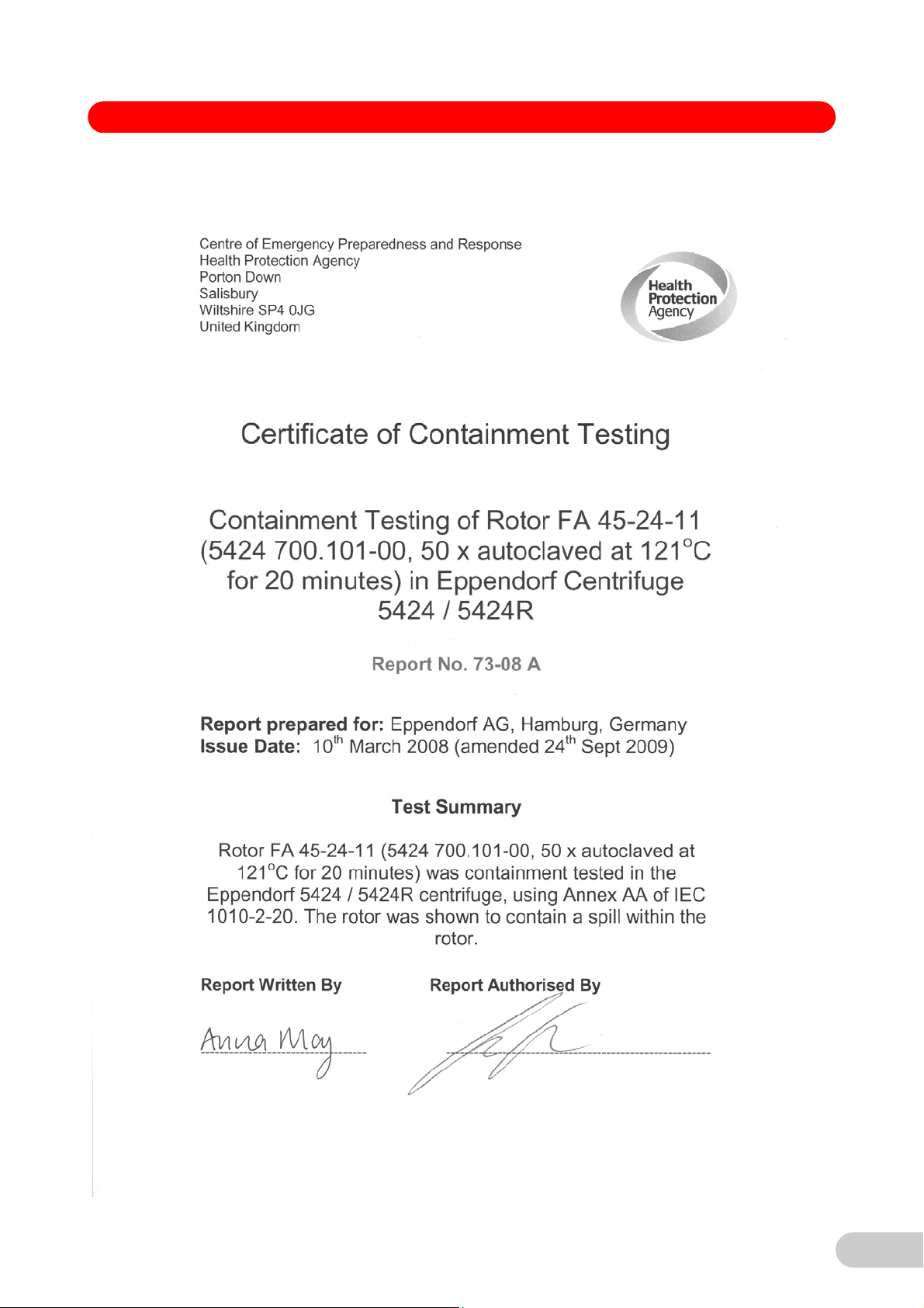
Declarations and Certificates
179
Page 43

Declarations and Certificates
180
Page 44
In touch with life
Your local distributor: www .eppendorf.com/worldwide
Eppendorf AG · 22331 Hamburg · Germany · Tel: +49 40 53801-0 · Fax: +49 40 538 01-556 · E-mail: eppendorf@eppendorf.com
Eppendorf North America, Inc. · 102 Motor Parkway · Hauppauge, N.Y. 11788-5178 · USA
Tel: +1 516 334 7500 · Toll free phone: +1 800-645-3050 · Fax: +1 516 334 7506 · E-mail: info@eppendorf.com
Application Support Europe: Tel: +49 1803 666 789 (Preis je nach Tarif im Ausland; 9 ct/min aus dem dt. Festnetz; Mobilfunkhöchstpreis 42 ct/min)
support@eppendorf.com
North America: Tel: +1 800 645 3050 · E-mail: techserv@eppendorf.com
Asia Pacific: Tel: +60 3 8023 6869 · E-mail: support_asiapacific@eppendorf.com
 Loading...