

Page 1

DRAFT
DRAFT DRAFT DRAFT DRAFT DRAFT DRAFT
DRAFT DRAFT DRAFT
BA01854T/09/EN/01.18
71413522
2018-07-10
Valid as of version
01.00 (device version)
Products Solutions Services
Operating Instructions
iTEMP TMT71/72
Temperature transmitter
Preliminary version:
03-12-2018
Page 2

DRAFT
DRAFT DRAFT DRAFT DRAFT DRAFT DRAFT
DRAFT DRAFT DRAFT
Page 3

DRAFT
DRAFT DRAFT DRAFT DRAFT DRAFT DRAFT
DRAFT DRAFT DRAFT
iTEMP TMT71/72 Table of contents
Table of contents
1 About this document . . . . . . . . . . . . . . . . 4
1.1 Document function . . . . . . . . . . . . . . . . . . . . . 4
1.2 Safety Instructions (XA) . . . . . . . . . . . . . . . . . . 4
1.3 Symbols used . . . . . . . . . . . . . . . . . . . . . . . . . . 4
1.4 Tool symbols . . . . . . . . . . . . . . . . . . . . . . . . . . 5
1.5 Documentation . . . . . . . . . . . . . . . . . . . . . . . . 6
1.6 Registered trademarks . . . . . . . . . . . . . . . . . . . 6
2 Basic safety instructions . . . . . . . . . . . . 7
2.1 Requirements for the personnel . . . . . . . . . . . . 7
2.2 Designated use . . . . . . . . . . . . . . . . . . . . . . . . 7
2.3 Operational safety . . . . . . . . . . . . . . . . . . . . . . 7
3 Incoming acceptance and product
identification . . . . . . . . . . . . . . . . . . . . . . . 8
3.1 Incoming acceptance . . . . . . . . . . . . . . . . . . . . 8
3.2 Product identification . . . . . . . . . . . . . . . . . . . . 8
3.3 Scope of delivery . . . . . . . . . . . . . . . . . . . . . . . 9
3.4 Certificates and approvals . . . . . . . . . . . . . . . . 9
3.5 Transport and storage . . . . . . . . . . . . . . . . . . . 9
4 Installation . . . . . . . . . . . . . . . . . . . . . . . 10
4.1 Installation conditions . . . . . . . . . . . . . . . . . . 10
4.2 Installation . . . . . . . . . . . . . . . . . . . . . . . . . . 10
4.3 Post-installation check . . . . . . . . . . . . . . . . . . 14
5 Electrical connection . . . . . . . . . . . . . . 15
5.1 Connection conditions . . . . . . . . . . . . . . . . . . 15
5.2 Quick wiring guide . . . . . . . . . . . . . . . . . . . . . 15
5.3 Connecting the sensor cables . . . . . . . . . . . . . 16
5.4 Connecting the transmitter . . . . . . . . . . . . . . 16
5.5 Special connection instructions . . . . . . . . . . . . 16
5.6 Post-connection check . . . . . . . . . . . . . . . . . . 17
6 Operation options . . . . . . . . . . . . . . . . . 18
6.1 Overview of operation options . . . . . . . . . . . . 18
6.2 Structure and function of the operating
menu . . . . . . . . . . . . . . . . . . . . . . . . . . . . . . 21
6.3 Access to the operating menu via the
operating tool . . . . . . . . . . . . . . . . . . . . . . . . 23
6.4 Access to the operating menu via the
SmartBlue App . . . . . . . . . . . . . . . . . . . . . . . 26
7 System integration . . . . . . . . . . . . . . . . 28
7.1 Overview of device description files . . . . . . . . . 28
7.2 Measured variables via HART protocol . . . . . . 28
8.2 Switching on the transmitter . . . . . . . . . . . . . 31
8.3 Configuring the measuring device . . . . . . . . . . 31
8.4 Protecting settings from unauthorized
access . . . . . . . . . . . . . . . . . . . . . . . . . . . . . . 33
9 Diagnostics and troubleshooting . . . 35
9.1 General troubleshooting . . . . . . . . . . . . . . . . . 35
9.2 Diagnostic information on local display . . . . . . 37
9.3 Diagnostic information via communication
interface . . . . . . . . . . . . . . . . . . . . . . . . . . . . 38
9.4 Diagnostic list . . . . . . . . . . . . . . . . . . . . . . . . 38
9.5 Event logbook . . . . . . . . . . . . . . . . . . . . . . . . 38
9.6 Overview of diagnostic events . . . . . . . . . . . . . 39
9.7 Firmware history . . . . . . . . . . . . . . . . . . . . . . 40
10 Maintenance . . . . . . . . . . . . . . . . . . . . . . 41
11 Repair . . . . . . . . . . . . . . . . . . . . . . . . . . . . 41
11.1 General information . . . . . . . . . . . . . . . . . . . 41
11.2 Spare parts . . . . . . . . . . . . . . . . . . . . . . . . . . 41
11.3 Return . . . . . . . . . . . . . . . . . . . . . . . . . . . . . . 41
11.4 Disposal . . . . . . . . . . . . . . . . . . . . . . . . . . . . 41
12 Accessories . . . . . . . . . . . . . . . . . . . . . . . 41
12.1 Device-specific accessories . . . . . . . . . . . . . . . 42
12.2 Communication-specific accessories . . . . . . . . 42
12.3 Service-specific accessories . . . . . . . . . . . . . . . 43
12.4 System components . . . . . . . . . . . . . . . . . . . . 44
13 Technical data . . . . . . . . . . . . . . . . . . . . 45
13.1 Input . . . . . . . . . . . . . . . . . . . . . . . . . . . . . . . 45
13.2 Output . . . . . . . . . . . . . . . . . . . . . . . . . . . . . 46
13.3 Power supply . . . . . . . . . . . . . . . . . . . . . . . . . 47
13.4 Performance characteristics . . . . . . . . . . . . . . 48
13.5 Environment . . . . . . . . . . . . . . . . . . . . . . . . . 55
13.6 Mechanical construction . . . . . . . . . . . . . . . . 56
13.7 Certificates and approvals . . . . . . . . . . . . . . . 58
13.8 Supplementary documentation . . . . . . . . . . . . 60
14 Operating menu and parameter
description . . . . . . . . . . . . . . . . . . . . . . . . 61
14.1 Menu: Diagnostics . . . . . . . . . . . . . . . . . . . . . 65
14.2 Menu: Application . . . . . . . . . . . . . . . . . . . . . 71
14.3 Menu: System . . . . . . . . . . . . . . . . . . . . . . . . 81
7.3
Supported HART® commands . . . . . . . . . . . . .
28
8 Commissioning . . . . . . . . . . . . . . . . . . . . 31
8.1 Post-installation check . . . . . . . . . . . . . . . . . . 31
Endress+Hauser V. 1, Rev. 2, 4-10-2018 3
Page 4

DRAFT
DRAFT DRAFT DRAFT DRAFT DRAFT DRAFT
DRAFT DRAFT DRAFT
About this document iTEMP TMT71/72
1 About this document
1.1 Document function
These Operating Instructions contain all the information that is required in various phases
of the life cycle of the device: from product identification, incoming acceptance and
storage, to mounting, connection, operation and commissioning through to
troubleshooting, maintenance and disposal.
1.2 Safety Instructions (XA)
When using in hazardous areas, compliance with national regulations is mandatory.
Separate Ex-specific documentation is provided for measuring systems that are used in
hazardous areas. This documentation is an integral part of these Operating Instructions.
The installation specifications, connection data and safety instructions it contains must be
strictly observed! Make sure that you use the right Ex-specific documentation for the right
device with approval for use in hazardous areas! The number of the specific Ex
documentation (XA...) is provided on the nameplate. If the two numbers (on the Ex
documentation and the nameplate) are identical, then you may use this Ex-specific
documentation.
1.3 Symbols used
1.3.1 Safety symbols
Symbol Meaning
DANGER
WARNING
CAUTION
NOTICE
DANGER!
This symbol alerts you to a dangerous situation. Failure to avoid this situation will
result in serious or fatal injury.
WARNING!
This symbol alerts you to a dangerous situation. Failure to avoid this situation can
result in serious or fatal injury.
CAUTION!
This symbol alerts you to a dangerous situation. Failure to avoid this situation can
result in minor or medium injury.
NOTE!
This symbol contains information on procedures and other facts which do not result in
personal injury.
1.3.2 Electrical symbols
Symbol Meaning
Direct current
Alternating current
Direct current and alternating current
4 V. 1, Rev. 2, 4-10-2018 Endress+Hauser
Page 5
DRAFT
DRAFT DRAFT DRAFT DRAFT DRAFT DRAFT
DRAFT DRAFT DRAFT
iTEMP TMT71/72 About this document
Symbol Meaning
Ground connection
A grounded terminal which, as far as the operator is concerned, is grounded via a
grounding system.
Protective Earth (PE)
A terminal which must be connected to ground prior to establishing any other
connections.
The ground terminals are situated inside and outside the device:
• Inner ground terminal: Connects the protectiv earth to the mains supply.
• Outer ground terminal: Connects the device to the plant grounding system.
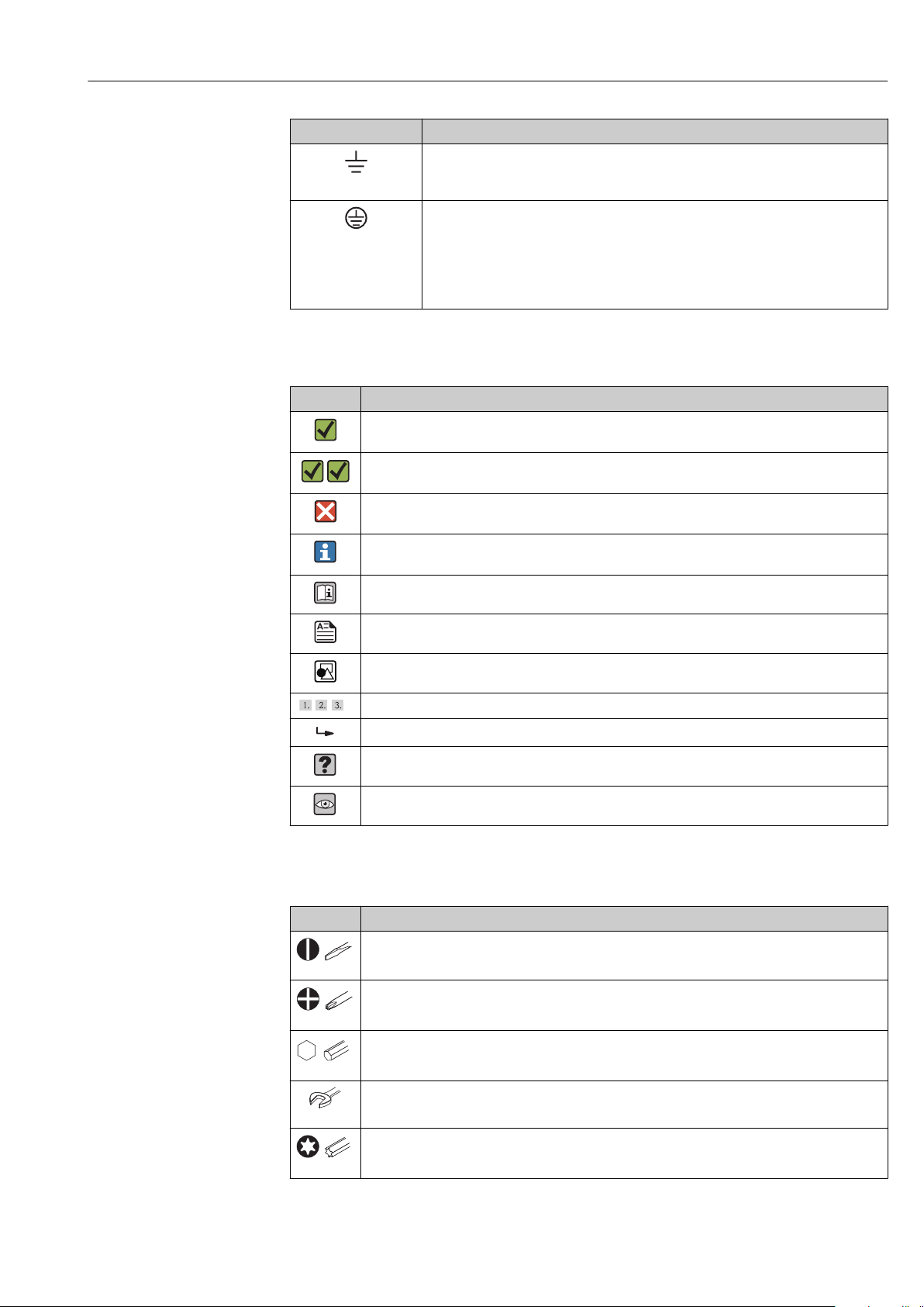
1.3.3 Symbols for certain types of information
Symbol Meaning
Permitted
Procedures, processes or actions that are permitted.
Preferred
Procedures, processes or actions that are preferred.
Forbidden
Procedures, processes or actions that are forbidden.
Tip
Indicates additional information.
Reference to documentation
Reference to page
Reference to graphic
, , …
Series of steps
Result of a step
Help in the event of a problem
Visual inspection
1.4 Tool symbols
Symbol Meaning
Flat blade screwdriver
A0011220
Phillips head screwdriver
A0011219
Allen key
A0011221
Open-ended wrench
A0011222
Torx screwdriver
A0013442
Endress+Hauser V. 1, Rev. 2, 4-10-2018 5
Page 6

DRAFT
DRAFT DRAFT DRAFT DRAFT DRAFT DRAFT
DRAFT DRAFT DRAFT
About this document iTEMP TMT71/72
1.5 Documentation
Document Purpose and content of the document
Technical Information
TI01392T/09/en
Brief Operating Instructions
KA01384T/09/en
Planning aid for your device
The document contains all the technical data on the device and provides
an overview of the accessories and other products that can be ordered for
the device.
Guide that takes you quickly to the 1st measured value
The Brief Operating Instructions contain all the essential information
from incoming acceptance to initial commissioning.
The document types listed are available:
In the Download Area of the Endress+Hauser Internet site: www.endress.com →
Download
1.6 Registered trademarks
HART®
Registered trademark of the HART® FieldComm Group
6 V. 1, Rev. 2, 4-10-2018 Endress+Hauser
Page 7

DRAFT
DRAFT DRAFT DRAFT DRAFT DRAFT DRAFT
DRAFT DRAFT DRAFT
iTEMP TMT71/72 Basic safety instructions
2 Basic safety instructions
2.1 Requirements for the personnel
The personnel for installation, commissioning, diagnostics and maintenance must fulfill
the following requirements:
‣
‣‣‣
‣
Trained, qualified specialists must have a relevant qualification for this specific function
and task
Are authorized by the plant owner/operator
Are familiar with federal/national regulations
Before beginning work, the specialist staff must have read and understood the
instructions in the Operating Instructions and supplementary documentation as well as
in the certificates (depending on the application)
Following instructions and basic conditions
The operating personnel must fulfill the following requirements:
Being instructed and authorized according to the requirements of the task by the
facility's owner-operator
‣
Following the instructions in these Operating Instructions
2.2 Designated use
The device is a universal and user-configurable temperature transmitter with one sensor
input for a resistance thermometer (RTD), thermocouples (TC), resistance and voltage
transmitters. The head transmitter version of the device is intended for mounting in a
terminal head (flat face) as per DIN EN 50446. It is also possible to mount the device on a
DIN rail using the optional DIN rail clip.
The manufacturer is not liable for damage caused by improper or non-designated use.
2.3 Operational safety
‣
‣
Operate the device in proper technical condition and fail-safe condition only.
The operator is responsible for interference-free operation of the device.
Hazardous area
To eliminate a danger for persons or for the facility when the device is used in the
hazardous area (e.g. explosion protection or safety equipment):
‣
‣
Based on the technical data on the nameplate, check whether the ordered device is
permitted for the intended use in the hazardous area. The nameplate can be found on
the side of the transmitter housing.
Observe the specifications in the separate supplementary documentation that is an
integral part of these Instructions.
Electromagnetic compatibility
The measuring system complies with the general safety requirements as per EN 61010-1,
the EMC requirements as per the IEC/EN 61326 series and the NAMUR recommendations
NE 21.
NOTICE
‣
The device must only be powered by a power unit that operates using an energy-limited
electric circuit according to IEC 61010-1, "SELV or Class 2 circuit".
Endress+Hauser V. 1, Rev. 2, 4-10-2018 7
‣
Page 8
DRAFT
DRAFT DRAFT DRAFT DRAFT DRAFT DRAFT
DRAFT DRAFT DRAFT
Incoming acceptance and product identification iTEMP TMT71/72
3 Incoming acceptance and product
identification
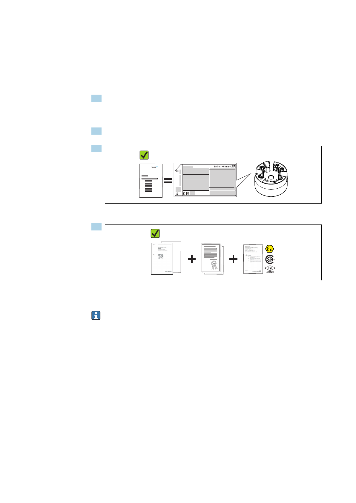
3.1 Incoming acceptance
1. Unpack the temperature transmitter carefully. Is the packaging or content damaged?
Damaged components may not be installed as the manufacturer can otherwise
not guarantee compliance with the original safety requirements or the material
resistance, and can therefore not be held responsible for any resulting damage.
2. Is the delivery complete or is anything missing? Check the scope of delivery against
your order.
3.
DELIVERY NOTE
A0037102
Does the nameplate match the ordering information on the delivery note?
4.
A0024858
Are the technical documentation and all other necessary documents provided? If
applicable: are the Safety Instructions (e.g. XA) for hazardous areas provided?
If one of these conditions is not satisfied, contact your Endress+Hauser Sales Center.
3.2 Product identification
The following options are available for identification of the device:
• Nameplate specifications
• Extended order code with breakdown of the device features on the delivery note
• Enter the serial number from the nameplate in the W@M Device Viewer
(www.endress.com/deviceviewer): All data relating to the device and an overview of the
Technical Documentation supplied with the device are displayed.
• Enter the serial number on the nameplate into the Endress+Hauser Operations App or
scan the 2-D matrix code (QR code) on the nameplate with the Endress+Hauser
Operations App: all the information about the device and the technical documentation
pertaining to the device is displayed.
3.2.1 Nameplate
The right device?
Compare and check the data on the nameplate of the device against the requirements of
the measuring point:
8 V. 1, Rev. 2, 4-10-2018 Endress+Hauser
TMT71/72
Page 9

DRAFT
DRAFT DRAFT DRAFT DRAFT DRAFT DRAFT
DRAFT DRAFT DRAFT
11-42V
012345678910
xx.yy.zz
TMT82- XXXXX/XX
iTEMP
Ser.no.:
FW:
Input:
12345678ABCDEFGH
12345678ABCDEFGH
Dev.Rev: x
Ext. ord. cd.:
XXXXXXXXXXXXX#
0044
iTEMP TMT71/72 Incoming acceptance and product identification
3
7
Made in Germany 201x
D-87484 Nesselwang
A0014561
1 Nameplate of the head transmitter (example, Ex version)
1 Power supply, current consumption and radio approval (Bluetooth)
2 Serial number, device revision, firmware version and hardware version
3 Data Matrix 2D code
4 2 lines for the TAG name and extended order code
5 Approval in hazardous area with number of the relevant Ex documentation (XA...)
6 Approvals with symbols
7 Order code and manufacturer ID
3.3 Scope of delivery
The scope of delivery of the device comprises:
• Temperature transmitter
• Mounting material (head transmitter), optional
• Hard copy of multi-language Brief Operating Instructions
• Additional documentation for devices which are suitable for use in the hazardous area
(0 1 ), such as Safety Instructions (XA...), Control or Installation Drawings (ZD...).
3.4 Certificates and approvals
The device left the factory in a safe operating condition. The device complies with the
requirements of the standards EN 61 010-1 "Safety Requirements for Electrical Equipment
for Measurement, Control, and Laboratory Use" and with the EMC requirements as per the
IEC/EN 61326 series.
3.4.1 CE/EAC mark, declaration of conformity
The device meets the legal requirements of the EU/EEU guidelines. The manufacturer
confirms that the device is compliant with the relevant guidelines by applying the CE/EAC
mark.
3.4.2
HART® protocol certification
The temperature transmitter is registered by the HART® FieldComm Group. The device
meets the requirements of the HART Communication Protocol Specifications, Revision 7
(HCF 7.6).
3.5 Transport and storage
Carefully remove all the packaging material and protective covers that are part of the
transported package.
Dimensions and operating conditions: → 56
When storing (and transporting) the device, pack it so that it is reliably protected
against impact. The original packaging offers the best protection.
Storage temperature
Head transmitter: –50 to +100 °C (–58 to +212 °F)
Endress+Hauser V. 1, Rev. 2, 4-10-2018 9
1
254
6
Page 10

DRAFT
DRAFT DRAFT DRAFT DRAFT DRAFT DRAFT
DRAFT DRAFT DRAFT
Installation iTEMP TMT71/72
4 Installation
4.1 Installation conditions
4.1.1 Dimensions
The dimensions of the device are provided in the "Technical data" section → 56.
4.1.2 Mounting location
Head transmitter:
– In the terminal head, flat face, as per DIN EN 50446, direct mounting on insert with
cable entry (middle hole 7 mm)
– In the field housing, separated from the process→ 41
It is also possible to mount the head transmitter on a DIN rail as per IEC 60715 using
the DIN rail clip → 41accessory.
Information about the conditions (such as the ambient temperature, degree of protection,
climate class etc.) that must be present at the installation point so that the device can be
mounted correctly is provided in the "Technical data" section→ 55.
When using in hazardous areas, the limit values of the certificates and approvals must be
observed (see Ex Safety Instructions).
4.2 Installation
A Phillips head screwdriver is required to mount the head transmitter.
NOTICE
Do not overtighten the mounting screws as this could damage the head transmitter.
‣
Maximum torque = 1 Nm (¾ pound-feet).
10 V. 1, Rev. 2, 4-10-2018 Endress+Hauser
Page 11

DRAFT
DRAFT DRAFT DRAFT DRAFT DRAFT DRAFT
DRAFT DRAFT DRAFT
iTEMP TMT71/72 Installation
4.2.1 Mounting the head transmitter
Item A Item B
8
9
Item C
7
6
5
4
3
2
1
120 mm
(4.72 in)
120 mm
(4.72 in)
1 2 3 4 5
1
2
3 4
A0014269-EN
2 Head transmitter mounting (three versions)
Item A Mounting in a terminal head (terminal head flat face as per DIN 43729)
1 Terminal head
2 Circlips
3 Insert
4 Connection wires
5 Head transmitter
6 Mounting springs
7 Mounting screws
8 Terminal head cover
9 Cable entry
Procedure for mounting in a terminal head, pos. A:
1. Open the terminal head cover (8) on the terminal head.
2. Guide the connection wires (4) of the insert (3) through the center hole in the head
transmitter (5).
3. Fit the mounting springs (6) on the mounting screws (7).
4. Guide the mounting screws (7) through the side boreholes of the head transmitter
and the insert (3). Then fix both mounting screws with the snap rings (2).
5. Then tighten the head transmitter (5) along with the insert (3) in the terminal head.
6. After wiring→ 15, close the terminal head cover (8) tightly again.
Endress+Hauser V. 1, Rev. 2, 4-10-2018 11
Page 12
DRAFT
DRAFT DRAFT DRAFT DRAFT DRAFT DRAFT
DRAFT DRAFT DRAFT
Installation iTEMP TMT71/72
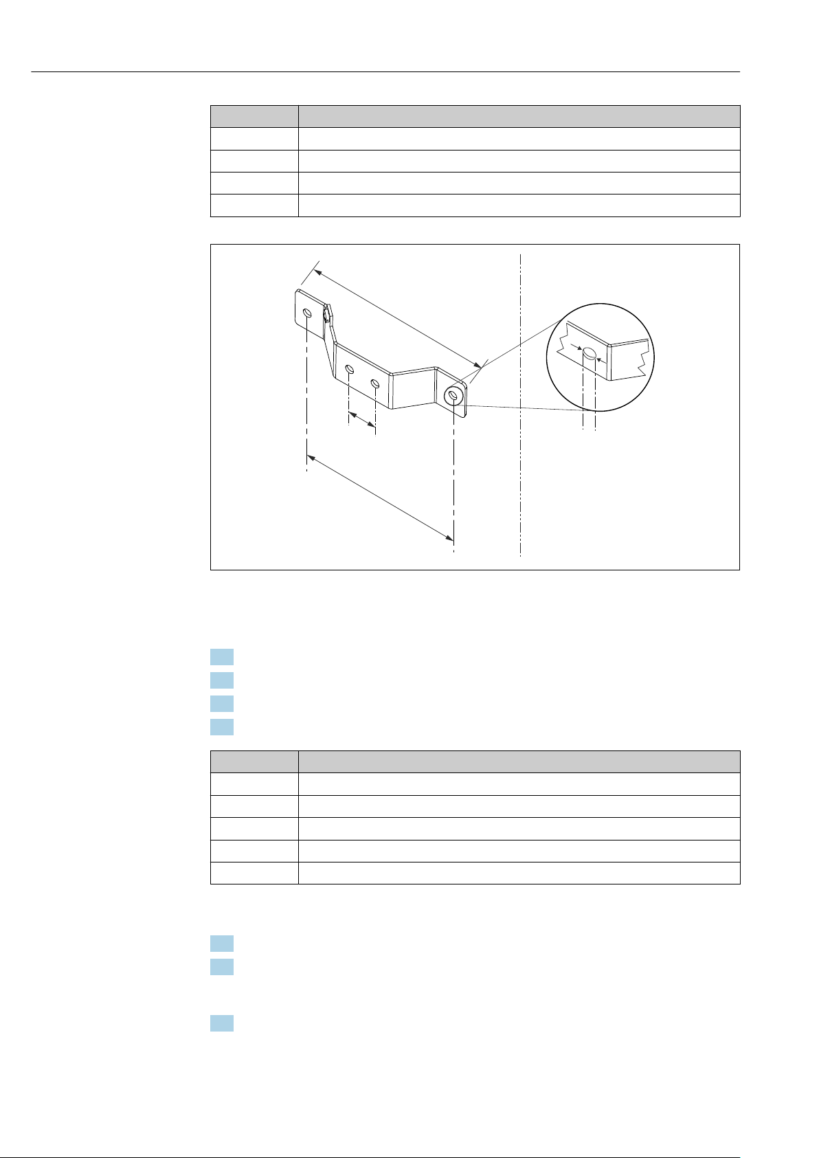
Item B Mounting in a field housing
1 Field housing cover
2 Mounting screws with springs
3 Head transmitter
5 Field housing
140 mm
(5.51 in)
21 mm
(0.83 in)
! 6.5 mm
(0.25 in)
120 mm
(4.72 in)
A0024604
3 Dimensions of angle bracket for wall mount (complete wall mounting set available as accessory)
Procedure for mounting in a field housing, pos. B:
1. Open the cover (1) of the field housing (4).
2. Guide the mounting screws (2) through the lateral bores in the head transmitter (3).
3. Screw the head transmitter to the field housing.
4. After wiring, close the field housing cover (1) → 15again.
Item C Mounting on DIN rail (DIN rail as per IEC 60715)
1 Mounting screws with springs
2 Head transmitter
3 Circlips
4 DIN rail clip
5 DIN rail
Procedure for mounting on a DIN rail, pos. C:
1. Press the DIN rail clip (4) onto the DIN rail (5) until it engages with a click.
2. Fit the mounting springs on the mounting screws (1) and guide the screws through
the side boreholes of the head transmitter (2). Then fix both mounting screws with
the snap rings (3).
3. Screw the head transmitter (2) onto the DIN rail clip (4).
12 V. 1, Rev. 2, 4-10-2018 Endress+Hauser
Page 13
DRAFT
DRAFT DRAFT DRAFT DRAFT DRAFT DRAFT
DRAFT DRAFT DRAFT
iTEMP TMT71/72 Installation
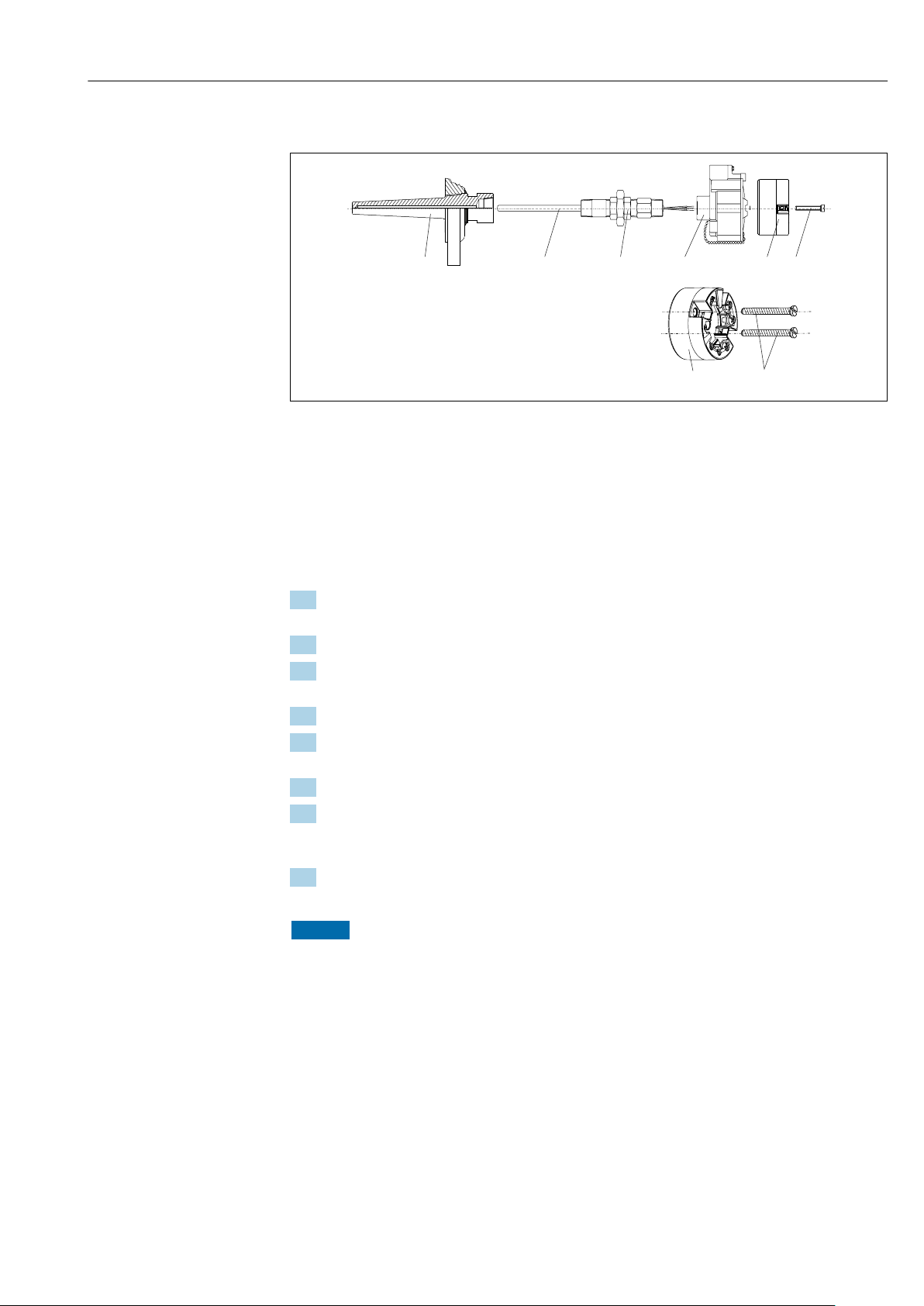
Mounting typical of North America
1
2 3 4 5
6
5
6
A0008520
4 Head transmitter mounting
1 Thermowell
2 Insert
3 Adapter, coupling
4 Terminal head
5 Head transmitter
6 Mounting screws
Thermometer design with thermocouples or RTD sensors and head transmitter:
1. Fit the thermowell (1) on the process pipe or the container wall. Secure the
thermowell according to the instructions before the process pressure is applied.
2. Fit the necessary neck tube nipples and adapter (3) on the thermowell.
3. Make sure sealing rings are installed if such rings are needed for harsh
environmental conditions or special regulations.
4. Guide the mounting screws (6) through the lateral bores of the head transmitter (5).
5. Position the head transmitter (5) in the terminal head (4) in such a way that the bus
cable (terminals 1 and 2) point to the cable entry.
6. Using a screwdriver, screw down the head transmitter (5) in the terminal head (4).
7. Guide the connection wires of the insert (3) through the lower cable entry of the
terminal head (4) and through the middle hole in the head transmitter (5). Wire the
connection wires up to the transmitter → 15.
8. Screw the terminal head (4), with the integrated and wired head transmitter, onto
the ready-mounted nipple and adapter (3).
NOTICE
The terminal head cover must be secured properly to meet the requirements for
explosion protection.
‣
After wiring, securely screw the terminal head cover back on.
Endress+Hauser V. 1, Rev. 2, 4-10-2018 13
Page 14

DRAFT
DRAFT DRAFT DRAFT DRAFT DRAFT DRAFT
DRAFT DRAFT DRAFT
Installation iTEMP TMT71/72
Mounting the display on the head transmitter
A0009852
5 Mounting the display
1. Loosen the screw on the terminal head cover. Flip back the terminal head cover.
2. Remove the cover of the display connection area.
3. Fit the display module onto the mounted and wired head transmitter. The fastening
pins must click securely into place on the head transmitter. After mounting, securely
tighten the terminal head cover.
The display can be used only with the appropriate terminal heads - cover with viewing
window (e.g. TA30 from Endress+Hauser).
4.3 Post-installation check
After installing the device, always run the following final checks:
Device condition and specifications Notes
Is the device undamaged (visual inspection)? -
Do the ambient conditions match the device specification (e.g. ambient temperature,
measuring range, etc.)?
See 'Technical data'
section
14 V. 1, Rev. 2, 4-10-2018 Endress+Hauser
Page 15

DRAFT
DRAFT DRAFT DRAFT DRAFT DRAFT DRAFT
DRAFT DRAFT DRAFT
-
+
+
-
iTEMP TMT71/72 Electrical connection
5 Electrical connection
5.1 Connection conditions
L
CAUTION
‣
‣
‣
Switch off the power supply before installing or connecting the device. Failure to
observe this may result in the destruction of parts of the electronics.
When connecting Ex-certified devices, please take special note of the instructions and
connection schematics in the Ex-specific supplement to these Operating Instructions.
Your supplier is available for assistance if required.
Do not occupy the display connection. An incorrect connection can destroy the
electronics.
NOTICE
Do not overtighten the screw terminals, as this could damage the transmitter. Use a
suitable screwdriver.
‣
‣
Maximum torque for securing screws = 1 Nm (¾ foot-pound), screwdriver: Pozidriv Z2
Maximum torque for screw terminals = 0.35 Nm (¼ foot-pound), screwdriver: Pozidriv
Z1
Proceed as follows to wire a mounted head transmitter:
1. Open the cable gland and the housing cover on the terminal head or the field
housing.
2. Feed the cables through the opening in the cable gland.
3. Connect the cables as shown in → 15.
4. Tighten the cable gland again and close the housing cover.
In order to avoid connection errors always follow the instructions in the post-connection
check section before commissioning!
5.2 Quick wiring guide
red
red
TC, mV
white
white
Sensor input
RTD, ! : 4-, 3- and 2-wire
6
5
4
3
5
463
Bus connection
and supply voltage
1
1
2
2
Display connection/
service interface
A0036348-EN
6 Terminal assignment of head transmitter
To operate the device via the HART® protocol (terminals 1 and 2), a minimum load of 250
Ω is required in the signal circuit.
Endress+Hauser V. 1, Rev. 2, 4-10-2018 15
Page 16
DRAFT
DRAFT DRAFT DRAFT DRAFT DRAFT DRAFT
DRAFT DRAFT DRAFT
Electrical connection iTEMP TMT71/72
In the event of a thermocouple (TC) measurement, a 2-wire RTD can be connected to
measure the reference junction temperature. This is connected to terminals 4 and 6.
NOTICE
‣
ESD - electrostatic discharge. Protect the terminals from electrostatic discharge.
Failure to observe this may result in the destruction or malfunction of parts of the
electronics.
5.3 Connecting the sensor cables
Terminal assignment of the sensor connections→ 6, 15.
5.4 Connecting the transmitter
L
CAUTION
‣
Switch off power supply before installing or connecting the transmitter. Failure to
observe this may result in the destruction of parts of the electronics.
Cable specification
• A normal device cable suffices if only the analog signal is used.
• A shielded cable is recommended for HART® communication. Observe grounding
concept of the plant.
Please also observe the general procedure on → 15.
1 2 3
21+
2- 1+
2- 1+
!
4
5
6
7
!
4
7
!
5
A0017841
7 Connecting the signal cables and power supply
1 Head transmitter installed in field housing
2 Head transmitter installed in terminal head
3 DIN rail transmitter mounted on DIN rail
4
Terminals for HART® protocol and power supply
5 Internal ground connection
6 External ground connection
7
Shielded signal cable (recommended for HART® protocol)
• The terminals for connecting the signal cable (1+ and 2-) are protected against
reverse polarity.
• Conductor cross-section:
Max. 2.5 mm2 for screw terminals
5.5 Special connection instructions
Shielding and grounding
16 V. 1, Rev. 2, 4-10-2018 Endress+Hauser
Page 17

DRAFT
DRAFT DRAFT DRAFT DRAFT DRAFT DRAFT
DRAFT DRAFT DRAFT
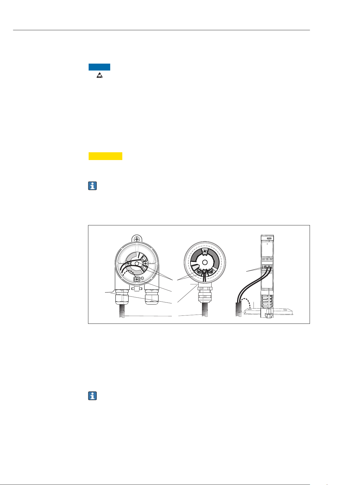
iTEMP TMT71/72 Electrical connection
The specifications of the HART FieldComm Group must be observed during installation.
3
1
2
-
.
4
A0014463
8
Shielding and grounding the signal cable at one end with HART® communication
1 Optional grounding of the field device, isolated from cable shielding
2 Grounding of the cable shield at one end
3 Supply unit
4
Grounding point for HART® communication cable shield
5.6 Post-connection check
Device condition and specifications Notes
Is the device or cable undamaged (visual check)? --
Electrical connection Notes
Does the supply voltage match the specifications on
the nameplate?
• Head transmitter: U = e.g. 10 to 36 V
DC
• Other values apply in the hazardous area, see the
corresponding Ex Safety Instructions (XA).
Do the cables have adequate strain relief? -Are the power supply and signal cables correctly → 15
connected?
Are all the screw terminals well tightened? -Are all the cable entries installed, tightened and --
sealed?
Are all housing covers installed and firmly tightened? --
Endress+Hauser V. 1, Rev. 2, 4-10-2018 17
Page 18

DRAFT
DRAFT DRAFT DRAFT DRAFT DRAFT DRAFT
DRAFT DRAFT DRAFT
Operation options iTEMP TMT71/72
6 Operation options
6.1 Overview of operation options
SmartBlue
App
FieldCare
PLC
TMT71/72
RN221N
HART Modem
A0036305
9 Operation options for the head transmitter
For the head transmitter, display and operating elements are available locally only if
the head transmitter was ordered with an attachable display unit!
The transmitter's optional Bluetooth interface is only active if a display unit is not
attached or the CDI interface is not used for device configuration.
6.1.1 Measured value display and operating elements
Option: display TID10 with transmitter
The display may also be subsequently ordered
at any time after purchasing the transmitter,
see the 'Accessories' section in the Operating
Instructions for the device.
A0010227
10 Attach the display to the transmitter
18 V. 1, Rev. 2, 4-10-2018 Endress+Hauser
Page 19

DRAFT
DRAFT DRAFT DRAFT DRAFT DRAFT DRAFT
DRAFT DRAFT DRAFT
iTEMP TMT71/72 Operation options
Display elements
Head transmitter
1
2
3
4
5
6
7
A0008549
11 Optional LC display for head transmitter
Item No. Function Description
1 Displays the TAG TAG, 32 characters long.
2 'Communication' symbol The communication symbol appears when read and write-accessing via
the fieldbus protocol.
3 Unit display Unit display for the measured value displayed.
4 Measured value display Displays the current measured value.
5 Value/channel display
DT, PV, I, %
6 'Configuration locked'
symbol
7 Status signals
e.g. PV for a measured value from channel 1 or DT for the device
temperature
The 'configuration locked' symbol appears when configuration is locked
via the hardware.
Symbols Meaning
Error message "Failure detected"
An operating error has occurred. The measured value is no longer valid.
The display alternates between the error message and "- - - -" (no valid
measured value present), see "Diagnostics events" section → 37.
The display alternates between the error message and "- - - -" (no valid
measured value present).
Detailed information on the error messages can be found in the
Operating Instructions.
"Service mode"
The device is in service mode (e.g. during a simulation).
"Out of specification"
The device is being operated outside its technical specifications (e.g.
during warm-up or cleaning processes).
"Maintenance required"
Maintenance is required. The measured value is still valid.
The display alternates between the measured value and the status
message.
Local operation
You can make hardware settings for the fieldbus interface using miniature switches (DIP
switches) on the rear of the optional display .
The user has the option of ordering the display with the head transmitter, or as an
accessory for subsequent mounting. → 41
NOTICE
‣
ESD - electrostatic discharge. Protect the terminals from electrostatic discharge.
Failure to observe this may result in the destruction or malfunction of parts of the
electronics.
Endress+Hauser V. 1, Rev. 2, 4-10-2018 19
Page 20

DRAFT
DRAFT DRAFT DRAFT DRAFT DRAFT DRAFT
DRAFT DRAFT DRAFT
Operation options iTEMP TMT71/72
32
64
H W
S W
ADDR A C T IV E
SIM
W R IT E L O C K
D I S P L . 1 8 0 °
1
2
3
1: Connection to head transmitter
2: DIP switches (1 - 64, SW/HW, ADDR and SIM = simulation
mode) no function for this head transmitter
3: DIP switch (WRITE LOCK = write protection; DISPL. 180° =
switch, turn the display monitor 180°)
A0014562
12 Hardware settings via DIP switches
Procedure for setting the DIP switch:
1. Open the cover of the terminal head or field housing.
2. Remove the attached display from the head transmitter.
3. Configure the DIP switch on the rear of the display accordingly. In general: switch to
ON = function enabled, switch to OFF = function disabled.
4. Fit the display onto the head transmitter in the correct position. The head transmitter
accepts the settings within one second.
5. Secure the cover back onto the terminal head or field housing.
Switching write protection on/off
Write protection is switched on and off via a DIP switch on the rear of the optional
attachable display. When write protection is active, parameters cannot be modified. A lock
symbol on the display indicates that the write protection is on. Write protection prevents
any write access to the parameters. The write protection remains active even when the
display is removed. To deactivate the write protection, the display must be attached to the
transmitter with the DIP switch switched off (WRITE LOCK = OFF). The transmitter adopts
the setting during operation and does not need to be restarted.
Turning the display
The display can be rotated 180° using the "DISPL. 180°" DIP switch. The setting is retained
when the display is removed.
20 V. 1, Rev. 2, 4-10-2018 Endress+Hauser
OFF
ON
1
2
4
8
16
Page 21

DRAFT
DRAFT DRAFT DRAFT DRAFT DRAFT DRAFT
DRAFT DRAFT DRAFT
iTEMP TMT71/72 Operation options
6.2 Structure and function of the operating menu
6.2.1 Structure of the operating menu
Actual Diagnostics
Actual diagnostics list
Previous diagnostics n
Diagnostic event simulation
Properties
Sensor min value
Sensor value
Unit
4 mA value
Assig n curren t outpu t (PV)
HART short tag
Bluetooth
Display interval
Alarm delay
Call./ v. Dusen coeff. R0...
New password
Password
Recover password
Old password
Squawk
Device type
Latitude
A0037574-EN
User roles
Endress+Hauser's role-based access concept consists of two hierarchical levels for the user
and presents the various user roles with defined read/write authorizations, derived from
the NAMUR shell model.
Endress+Hauser V. 1, Rev. 2, 4-10-2018 21
Diagnostics
Actual diagnostics
Guidance
+
-
+
Commissioning
Diagnostic list
Event logbook
Simulation
Diagnostic settings
Min/ max values
Application
Measured values
Sensor
Linearization
Current output
HA RT con fig ura tion
System
Device managemen t
User m a nagemen t
Define password
Enter password
Recover password
Change password
Delete password
Bluetooth config.
Information
Device
HART-Info
Device location
Display
Delete password
Page 22

DRAFT
DRAFT DRAFT DRAFT DRAFT DRAFT DRAFT
DRAFT DRAFT DRAFT
Operation options iTEMP TMT71/72
• Operator
The plant operator can only change settings that do not affect the application - and
particularly the measuring path - and simple, application-specific functions that are used
during operation. The operator is able to read all the parameters, however.
• Maintenance
The Maintenance user role refers to configuration situations: commissioning and
process adaptations as well as troubleshooting. It allows the user to configure and
modify all available parameters. In contrast to the Operator user role, in the
Maintenance role the user has read and write access to all the parameters.
• Changing the user role
A user role - and therefore existing read and write authorization - is changed by
selecting the desired user role (already pre-selected depending on the operating tool)
and entering the correct password when subsequently prompted. When a user logs out,
system access always returns to the lowest level in the hierarchy. A user is logged out
either by actively selecting the logout function when operating the device or is logged
out automatically if the device is not operated for a period of over 600 seconds.
Irrespective of this, actions that are already in progress (e.g. active upload/download,
data logging, etc.) continue to be executed in the background.
• As-delivered state
The Operator user role is not enabled when the device is delivered from the factory, i.e.
the Maintenance role is the lowest level in the hierarchy ex-works. This state makes it
possible to commission the device and make other process adaptations without having to
enter a password. Afterwards, a password can be assigned for the Maintenance user
role to protect this configuration. The Operator user role is not visible when the device is
delivered from the factory.
• Password
The Maintenance user role can assign a password in order to restrict access to device
functions. This activates the Operator user role, which is now the lowest hierarchy level
where the user is not asked to enter a password. The password can only be changed or
disabled in the Maintenance user role. A password can be defined at different points in
the operation of the device:
In the menu Guidance → Commissioning wizard: as part of guided device operation
In the menu: System → User management
22 V. 1, Rev. 2, 4-10-2018 Endress+Hauser
Page 23

DRAFT
DRAFT DRAFT DRAFT DRAFT DRAFT DRAFT
DRAFT DRAFT DRAFT
iTEMP TMT71/72 Operation options
Submenus
Menu Typical tasks Content/meaning
"Diagnostics" Fault elimination:
• Diagnosing and eliminating process errors.
• Error diagnostics in difficult cases.
• Interpretation of device error messages and
correcting associated errors.
"Application" Commissioning:
• Configuration of the measurement.
• Configuration of data processing (scaling,
linearization, etc.).
• Configuration of the analog measured value output.
Tasks during operation:
Reading measured values.
"System" Tasks that require detailed knowledge of the system
administration of the device:
• Optimum adaptation of the measurement for
system integration.
• Detailed configuration of the communication
interface.
• User and access administration, password control
• Information concerning the device identification,
HART information and display configuration
Contains all parameters for detecting and analyzing errors:
• Diagnostic list
Contains up to 3 error messages currently pending
• Event logbook
Contains the last 10 error messages (no longer pending)
• "Simulation" submenu
Used to simulate measured values, output values or diagnostic
messages
• "Diagnostic settings" submenu
Contains all the parameters for configuring error events
• "Min/max values" submenu
Contains the minimum/maximum indicator and the reset option
Contains all parameters for commissioning:
• "Measured values" submenu
Contains all the current measured values
• "Sensor" submenu
Contains all the parameters for configuring the measurement
• "Output" submenu
Contains all the parameters for configuring the analog current output
• "HART configuration" submenu
Contains the settings and the most important parameters for HART
communication
Contains all the higher-level device parameters that are assigned for
system, device and user management, including Bluetooth
configuration.
• "Device management" submenu
Contains parameters for general device management
• "Bluetooth configuration" submenu (option)
Contains the function for enabling/disabling the Bluetooth interface
• "Device and user management" submenus
Parameters for access authorization, password assignment, etc.
• "Information" submenu
Contains all the parameters for the unique identification of the device
• "Display" submenu
Configuration of the display
6.3 Access to the operating menu via the operating tool
6.3.1 DeviceCare
Function scope
DeviceCare is a free configuration tool for Endress+Hauser devices. It supports devices with
the following protocols, provided a suitable device driver (DTM) is installed: HART,
PROFIBUS, FOUNDATION Fieldbus, Ethernet/IP, Modbus, CDI, ISS, IPC and PCP. The tool is
aimed at customers without a digital network in plants and workshops and Endress
+Hauser service technicians. The devices can be connected directly via a modem (point-to-
point) or a bus system. DeviceCare is fast, easy and intuitive to use. It can run on a PC,
laptop or tablet with a Windows operating system.
Source for device description files
See information → 28
Endress+Hauser V. 1, Rev. 2, 4-10-2018 23
Page 24

DRAFT
DRAFT DRAFT DRAFT DRAFT DRAFT DRAFT
DRAFT DRAFT DRAFT
Operation options iTEMP TMT71/72
6.3.2 FieldCare
Function scope
FDT/DTM-based plant asset management tool from Endress+Hauser. It can configure all
smart field units in a system and help you manage them. By using the status information,
it is also a simple but effective way of checking their status and condition. Access takes
place via the HART® protocol or CDI (= Endress+Hauser Common Data Interface).
Typical functions:
• Configuring parameters of transmitters
• Loading and saving device data (upload/download)
• Documentation of the measuring point
• Visualization of the measured value memory (line recorder) and event logbook
For details, see Operating Instructions BA027S/04/xx and BA059AS/04/xx
Source for device description files
See information → 28
Establishing a connection
Example: via HART® modem Commubox FXA195 (USB)
1. Make sure that the DTM library is updated for all the connected devices (e.g.
FXA19x, TMTxy).
2. Start FieldCare and create a project.
3. Go to View --> Network: right-click Host PC Add device...
The Add device window opens.
4. Select the HART communication option from the list and press OK to confirm.
5. Double-click HART communication DTM instance.
Check whether the correct modem is connected to the serial interface and press
OK to confirm.
6. Right-click HART communication and select the Add device option in the context
menu that opens.
7. Select the desired device from the list and press OK to confirm.
The device now appears in the network list.
8. Right-click the device and select the Connect option in the context menu.
The CommDTM is displayed in green.
9. Double-click the device in the network to establish the online connection to the
device.
The online configuration is available.
If transferring the device parameters following an offline configuration, the password
for Maintenance - if assigned -must first be entered in the "User management" menu.
24 V. 1, Rev. 2, 4-10-2018 Endress+Hauser
Page 25
DRAFT
DRAFT DRAFT DRAFT DRAFT DRAFT DRAFT
DRAFT DRAFT DRAFT
iTEMP TMT71/72 Operation options
User interface
1 2 3 4 5 6 7
8
9
10
11
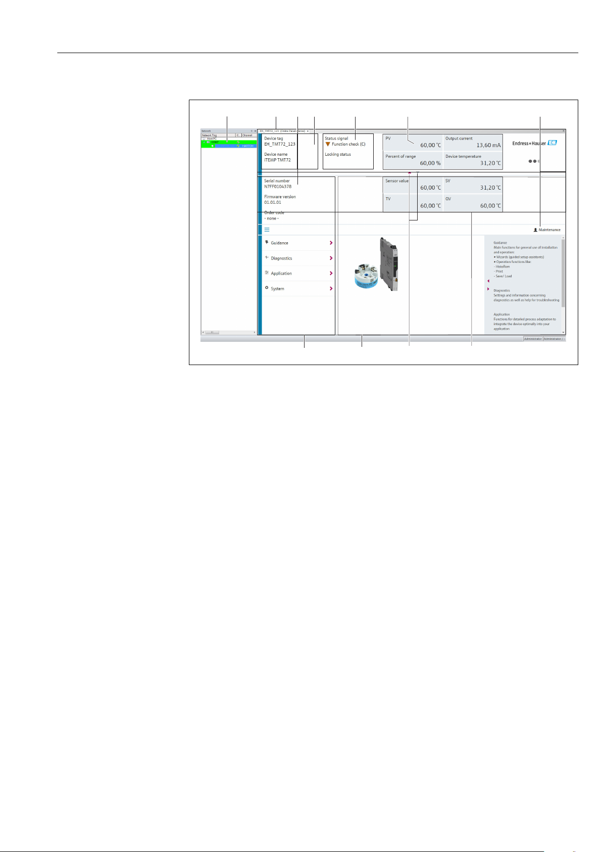
A0037232-EN
13 User interface with device information via HART® communication
1 Network view
2 Header
3 Extended header
4 Tag name and device name
5 Status signal
6 Measured values with device and measured value status information, simple presentation, e.g. PV, output
current, % span, device temperature
7 Current user role (with direct link to user management)
8 Navigation area with operating menu structure
9 Working area with fade in/fade out help area
10 Navigation arrows for fade in/fade out the extended header
11 Extended display of device and measured value information, e.g. sensor value, SV (TV, QV)
6.3.3 Field Xpert
Function scope
Field Xpert for mobile plant asset management is available as both a tablet PC and an
industrial PDA with an integrated touch screen for the commissioning and maintenance of
field devices in hazardous and non-hazardous areas. It enables the efficient configuration
of FOUNDATION fieldbus, HART and WirelessHART devices. Communication is wireless
via Bluetooth or WiFi interfaces.
Source for device description files
See information → 28.
6.3.4 AMS Device Manager
Function scope
Program from Emerson Process Management for operating and configuring measuring
devices via the HART® protocol.
Endress+Hauser V. 1, Rev. 2, 4-10-2018 25
Page 26

DRAFT
DRAFT DRAFT DRAFT DRAFT DRAFT DRAFT
DRAFT DRAFT DRAFT
Operation options iTEMP TMT71/72
Source for device description files
See information → 28.
6.3.5 SIMATIC PDM
Function scope
SIMATIC PDM is a standardized, manufacturer-independent program from Siemens for
the operation, configuration, maintenance and diagnosis of intelligent field devices via the
HART ® protocol.
Source for device description files
See information → 28.
6.3.6 Field Communicator 375/475
Function scope
Industrial handheld terminal from Emerson Process Management for remote
configuration and measured value display via the HART ® protocol.
Source for device description files
See information → 28.
6.4 Access to the operating menu via the SmartBlue App
The device can be operated and configured via the SmartBlue App. The connection is
established via the Bluetooth® wireless technology interface.
Prerequisite:
• The device has the optional Bluetooth interface: order code "Communication; output
signal; operation", option P: "HART; 4-20 mA; HART/Bluetooth (App) configuration"
• A smartphone or tablet with the SmartBlue App installed.
Supported functions
• Device selection in Live List and access to the device (login)
• Configuration of the device
• Access to measured values, device status and diagnostics information
The SmartBlue App is available for free download for Android devices (Google Playstore)
and iOS devices (iTunes Apple Shop) : Endress+Hauser SmartBlue
Directly to the app with the QR code:
A0033202
26 V. 1, Rev. 2, 4-10-2018 Endress+Hauser
Page 27

DRAFT
DRAFT DRAFT DRAFT DRAFT DRAFT DRAFT
DRAFT DRAFT DRAFT
iTEMP TMT71/72 Operation options
System requirements
• Devices with iOS:
– iPhone 4S or higher, from iOS9.0
– iPad2 or higher, from iOS9.0
– iPod Touch 5th generation or higher, from iOS9.0
• Devices with Android:
Android 4.4 KitKat or higher
Download the SmartBlue App:
1. Install and start the SmartBlue App.
A Live List shows all the devices available.
2. Select the device from the Live List.
The Login dialog box opens.
Logging in:
3. Enter the user name: admin
4. Enter the initial password: serial number of the device.
5. Confirm your entry.
The device information opens.
Navigate through the various items of information about the device: swipe the screen
to the side.
• The range under reference conditions is:
– 10 m (33 ft) when installed in the terminal head or field housing with a display
window
– 5 m (16.4 ft) when installed in the terminal head or field housing
• Incorrect operation by unauthorized persons is prevented by means of encrypted
communication and password encryption.
• The Bluetooth® wireless technology interface can be deactivated
The transmitter's optional Bluetooth interface is only active if a display unit is not
attached or the CDI interface is not used for device configuration.
Endress+Hauser V. 1, Rev. 2, 4-10-2018 27
Page 28

DRAFT
DRAFT DRAFT DRAFT DRAFT DRAFT DRAFT
DRAFT DRAFT DRAFT
System integration iTEMP TMT71/72
7 System integration
7.1 Overview of device description files
Version data for the device
Firmware version 01.01.zz • On the title page of the Operating instructions
• On the nameplate → 1, 9
• Parameter firmware version
Diagnostics → Device info→ Firmware Version
Manufacturer ID 0x11 Manufacturer ID parameter
Diagnostics → Device info→ Manufacturer ID
Device type ID 0x11D0 Device type parameter
Diagnostics → Device info → Device type
HART protocol revision 7 --Device revision 1 • On the transmitter nameplate → 1, 9
• Device revision parameter
Diagnostics → Device info → Device revision
The suitable device driver software (DD/DTM) for the individual operating tools can be
acquired from a variety of sources:
• www.endress.com --> Downloads --> Search field: Software --> Software type: Device
driver
• www.endress.com --> Products: individual product page, e.g. TMTx2 --> Documents /
Manuals / Software: Electronic Data Description (EDD) or Device Type Manager (DTM).
• Via DVD (please contact your local Endress+Hauser Sales Center)
Endress+Hauser supports all common operating tools from a variety of manufacturers (e.g.
Emerson Process Management, ABB, Siemens, Yokogawa, Honeywell and many others).
Endress+Hauser's FieldCare and DeviceCare operating tools are available for download
(www. endress.com --> Downloads --> Search field: Software --> Application software) or
on the optical data storage medium (DVD) which you can obtain from your local Endress
+Hauser Sales Center.
7.2 Measured variables via HART protocol
The following measured values are assigned to the device variables at the factory:
Device variable Measured value
Primary device variable (PV) Sensor
Secondary device variable (SV) Device temperature
Tertiary device variable (TV) Sensor
Quaternary device variable (QV) Sensor
7.3
Supported HART® commands
The HART® protocol enables the transfer of measuring data and device data between
the HART® master and the field device for configuration and diagnostics purposes.
HART® masters such as the handheld terminal or PC-based operating programs (e.g.
FieldCare) need device description files (DD, DTM) which are used to access all the
information in a HART® device. This information is transmitted exclusively via
"commands".
28 V. 1, Rev. 2, 4-10-2018 Endress+Hauser
Page 29

DRAFT
DRAFT DRAFT DRAFT DRAFT DRAFT DRAFT
DRAFT DRAFT DRAFT
iTEMP TMT71/72 System integration
There are three different types of command
• Universal commands:
All HART® devices support and use universal commands. These are associated with the
following functionalities for example:
– Recognition of HART® devices
– Reading digital measured values
• Common practice commands:
Common practice commands offer functions which are supported and can be executed by
many but not all field devices.
• Device-specific commands:
These commands allow access to device-specific functions which are not HART
®
standard. Such commands access individual field device information, among other
things.
Command No. Designation
Universal commands
0, Cmd0 Read unique identifier
1, Cmd001 Read primary variable
2, Cmd002 Read loop current and percent of range
3, Cmd003 Read dynamic variables and loop current
6, Cmd006 Write polling address
7, Cmd007 Read loop configuration
8, Cmd008 Read dynamic variable classifications
9, Cmd009 Read device variables with status
11, Cmd011 Read unique identifier associated with TAG
12, Cmd012 Read message
13, Cmd013 Read TAG, descriptor, date
14, Cmd014 Read primary variable transducer information
15, Cmd015 Read device information
16, Cmd016 Read final assembly number
17, Cmd017 Write message
18, Cmd018 Write TAG, descriptor, date
19, Cmd019 Write final assembly number
20, Cmd020 Read long TAG (32-byte TAG)
21, Cmd021 Read unique identifier associated with long TAG
22, Cmd022 Write long TAG (32-byte TAG)
38, Cmd038 Reset configuration changed flag
48, Cmd048 Read additional device status
Common practice commands
33, Cmd033 Read device variables
34, Cmd034 Write primary variable damping value
35, Cmd035 Write primary variable range values
40, Cmd040 Enter/Exit fixed current mode
42, Cmd042 Perform device reset
44, Cmd044 Write primary variable units
45, Cmd045 Trim loop current zero
46, Cmd046 Trim loop current gain
Endress+Hauser V. 1, Rev. 2, 4-10-2018 29
Page 30

DRAFT
DRAFT DRAFT DRAFT DRAFT DRAFT DRAFT
DRAFT DRAFT DRAFT
System integration iTEMP TMT71/72
Command No. Designation
50, Cmd050 Read dynamic variable assignments
54, Cmd054 Read device variable information
59, Cmd059 Write number of response preambles
72, Cmd072 Squawk
95, Cmd095 Read device communications statistics
100, Cmd100 Write primary variable alarm code
516, Cmd516 Read device location
517, Cmd517 Write device location
518, Cmd518 Read location description
519, Cmd519 Write location description
520, Cmd520 Read process unit tag
521, Cmd521 Write process unit tag
523, Cmd523 Read condensed status mapping array
524, Cmd524 Write condensed status mapping array
525, Cmd525 Reset condensed status mapping array
526, Cmd526 Write simulation mode
527, Cmd527 Simulate status bit
30 V. 1, Rev. 2, 4-10-2018 Endress+Hauser
Page 31

DRAFT
DRAFT DRAFT DRAFT DRAFT DRAFT DRAFT
DRAFT DRAFT DRAFT
iTEMP TMT71/72 Commissioning
8 Commissioning
8.1 Post-installation check
Before commissioning the measuring point make sure that all final checks have been
carried out:
• "Post-installation check" checklist→ 14
• "Post-connection check" checklist → 17
8.2 Switching on the transmitter
Once you have completed the post-connection checks, switch on the supply voltage. The
transmitter performs a number of internal test functions after power-up. As this procedure
progresses, the following sequence of messages appears on the display:
Step Display
1 "Display" text and firmware version of the display
2 Firm logo
3 Device name with firmware version, hardware version and device revision
4 Displays the sensor configuration (sensor type and type of connection) along with the configured
measuring range
5a Current measured value or
5b Current status message
If the switch-on procedure is not successful, the relevant diagnostic event, depending on the cause,
is displayed. A detailed list of diagnostic events and the corresponding troubleshooting instructions
can be found in the "Diagnostics and troubleshooting" section → 35.
The device operates in normal mode after approx. 7 seconds, including the attached
display. Normal measuring mode commences as soon as the switch-on procedure is
completed. Measured values and status values appear on the display.
If the display is attached when the Bluetooth interface is activated, display
initialization is performed twice and Bluetooth communication is disabled
simultaneously.
8.3 Configuring the measuring device
Wizards
The Guidance menu contains various wizards. Wizards not only query individual
parameters but also guide the user through the configuration and/or verification of entire
sets of parameters with step-by-step instructions, including questions, that are
comprehensible for the user. The "Start" button can be disabled for wizards that require
specific access authorization (keyhole symbol appears on the screen).
Endress+Hauser V. 1, Rev. 2, 4-10-2018 31
Page 32

DRAFT
DRAFT DRAFT DRAFT DRAFT DRAFT DRAFT
DRAFT DRAFT DRAFT
Commissioning iTEMP TMT71/72
The following five operating elements are supported for navigation in the wizards:
• Start
Only on the initial page: start the wizard and go to the first section
• Next
Go to the next page of the wizard. Is not enabled until parameters are entered or
confirmed.
• Back
Return to the previous page
• Cancel
If Cancel is selected, the status before the wizard was started is restored
• Finish
Closes the wizard and possibility of making additional parameter settings on the device.
Only enabled on the final page.
8.3.1 Commissioning wizard
Commissioning is the first step towards using the device for the designated application.
The Commissioning wizard contains an introductory page (with the "Start" operating
element) and a short description of the content. The wizard consists of several sections in
which the user is guided step-by-step through the commissioning of the device.
"Device management" is the first section that appears when the user runs the wizard, and
contains the following parameters. Its main purpose is to provide information about the
device:
Navigation Guidance→ Commissioning → Start
+
+
A0037378-EN
Device TAG
Device name
Serial number
Extended order code (n)
1)
HART short tag
HART date code
HART descriptor
HART message
1) n = placeholder for 1, 2, 3
The second section, "Sensor", takes the user through all the relevant settings for the sensor.
The number of parameters displayed depends on the corresponding settings. The following
parameters can be configured:
Navigation Guidance → Commissioning → Sensor
+
+
A0037389-EN
Unit
Sensor type
Connection type
2-wire compensation
Reference junction
RJ preset value
32 V. 1, Rev. 2, 4-10-2018 Endress+Hauser
Page 33

DRAFT
DRAFT DRAFT DRAFT DRAFT DRAFT DRAFT
DRAFT DRAFT DRAFT
iTEMP TMT71/72 Commissioning
In the third section, the settings are made for the analog output and the output's alarm
response. The following parameters can be configured:
Navigation Guidance → Commissioning → Current output
+
+
A0037390-EN
4 mA value
20 mA value
Failure mode
Failure current
In the final section, a password can be defined for the "Maintenance" user role. This is
strongly recommended to protect the device against unauthorized access. The following
steps describe how to configure a password for the "Maintenance" role for the first time.
Navigation Guidance → Commissioning → User management
+
+
A0037391-EN
Access status
New password
Confirm new password
1. The Maintenance role appears in the "Access status" picklist. The Maintenance user
role must first be selected when operating with the SmartBlue App.
Afterwards, the New password and Confirm new password input boxes appear.
2. Enter a user-defined password that meets the password rules indicated in the online
help.
3. Enter the password again in the Confirm new password input box.
Once the password has been entered successfully, parameter changes, particularly those
that are needed for commissioning, process adaptation/optimization and troubleshooting,
can only be implemented in the Maintenance user role and if the password is entered
successfully.
8.4 Protecting settings from unauthorized access
8.4.1 Hardware locking
The device can be protected against unauthorized access by hardware locking. In the
locking and access concept, hardware locking always has top priority. The device is write-
protected if the keyhole symbol appears in the header of the measured value display. To
disable write protection, switch the write protection switch on the back of the display to
the "OFF" position (hardware write protection). → 19
8.4.2 Software locking
By assigning a password for the Maintenance user role, it is possible to restrict access
authorization and protect the device against unauthorized access. See the Commissioning
wizard → 32
Commissioning wizard → 32
Endress+Hauser V. 1, Rev. 2, 4-10-2018 33
Page 34

DRAFT
DRAFT DRAFT DRAFT DRAFT DRAFT DRAFT
DRAFT DRAFT DRAFT
Commissioning iTEMP TMT71/72
The parameters are also protected against modification if the user logs out of the
Maintenance user role and the system switches to the Operator role. No keyhole symbol
is displayed, however.
To disable the write protection, the user must log on with the Maintenance user role via
the relevant operating tool.
User role concept → 21
34 V. 1, Rev. 2, 4-10-2018 Endress+Hauser
Page 35

DRAFT
DRAFT DRAFT DRAFT DRAFT DRAFT DRAFT
DRAFT DRAFT DRAFT
iTEMP TMT71/72 Diagnostics and troubleshooting
9 Diagnostics and troubleshooting
9.1 General troubleshooting
Always start troubleshooting with the checklists below if faults occur after start up or
during operation. The checklists take you directly (via various queries) to the cause of the
problem and the appropriate remedial measures.
Due to its design, the device cannot be repaired. However, it is possible to send the
device in for examination. See the information in the "Return" section. .→ 41
General errors
Problem Possible cause Remedy
Device is not responding. Supply voltage does not match that
specified on the nameplate.
Connecting cables are not in contact
with the terminals.
Check the voltage at the transmitter
directly using a voltmeter and correct.
Check the contacting of the cables and
correct if necessary.
Electronics unit is defective. Replace the device.
Output current < 3.6 mA Signal line is not wired correctly. Check wiring.
Electronics unit is defective. Replace the device.
HART communication is not
working.
Missing or incorrectly installed
communication resistor.
Install the communication resistor (250
Ω) correctly.
Commubox is connected incorrectly. Connect Commubox correctly.
Commubox is not set to "HART". Set Commubox selector switch to
"HART".
Check display (optional in conjunction with head transmitter)
Problem Possible cause Remedy
No supply voltage • Check the supply voltage at the head
transmitter, terminals + and -.
• Ensure that the display module
holders are correctly seated and that
the display module is properly
connected to the head transmitter
→ 10.
No display visible
• If possible, test the display module
with other suitable head transmitters,
e.g. an Endress+Hauser head
transmitter.
The display module is defective. Replace the module.
The electronics of the head Replace the head transmitter.
transmitter are defective.
Local error messages on the display
→ 37
Endress+Hauser V. 1, Rev. 2, 4-10-2018 35
Page 36

DRAFT
DRAFT DRAFT DRAFT DRAFT DRAFT DRAFT
DRAFT DRAFT DRAFT
Diagnostics and troubleshooting iTEMP TMT71/72
Faulty connection to the fieldbus host system
Problem Possible cause Remedy
Device is not
responding.
Supply voltage does not match that
specified on the nameplate.
Connecting cables are not in contact with
the terminals.
Check the voltage at the transmitter
directly using a voltmeter and correct.
Check the contacting of the cables and
correct if necessary.
Output current < 3.6
mA
Electronics unit is defective. Replace the device.
Signal line is not wired correctly. Check wiring.
Electronics unit is defective. Replace the device.
HART
communication is
not working.
Missing or incorrectly installed
communication resistor.
Install the communication resistor (250 Ω)
correctly.
Error messages in the configuration software
→ 38
Application errors without status messages for RTD sensor connection
Problem Possible cause Remedy
Incorrect sensor orientation. Install the sensor correctly.
Heat conducted by sensor. Observe the face-to-face length of the
Measured value is incorrect/
inaccurate
Device programming is incorrect
(number of wires).
Device programming is incorrect
(scaling).
sensor.
Change the Connection type device
function.
Change scaling.
Incorrect RTD configured. Change the Sensor type device function.
Sensor connection. Check that the sensor is connected
The cable resistance of the sensor (2wire) was not compensated.
correctly.
Compensate the cable resistance.
Offset incorrectly set. Check offset.
Faulty sensor. Check the sensor.
RTD connected incorrectly. Connect the connecting cables correctly
Failure current (≤ 3.6 mA or
≥ 21 mA)
Device programming is incorrect (e.g.
number of wires).
(terminal diagram).
Change the Connection type device
function.
Incorrect programming. Incorrect sensor type set in the Sensor
type device function. Set the correct
sensor type.
36 V. 1, Rev. 2, 4-10-2018 Endress+Hauser
Commubox is connected incorrectly. Connect Commubox correctly.
Page 37

DRAFT
DRAFT DRAFT DRAFT DRAFT DRAFT DRAFT
DRAFT DRAFT DRAFT
iTEMP TMT71/72 Diagnostics and troubleshooting
Application errors without status messages for TC sensor connection
Problem Possible cause Remedy
Incorrect sensor orientation. Install the sensor correctly.
Heat conducted by sensor. Observe the face-to-face length of the
Device programming is incorrect
(scaling).
sensor.
Change scaling.
Measured value is incorrect/
inaccurate
Incorrect thermocouple type (TC)
configured.
Incorrect reference measuring point
set.
Interference via the thermocouple
wire welded in the thermowell
(interference voltage coupling).
Change the Sensor type device function.
Set the correct reference measuring
point .
Use a sensor where the thermocouple
wire is not welded.
Failure current (≤ 3.6 mA or
≥ 21 mA)
Offset incorrectly set. Check offset.
Faulty sensor. Check the sensor.
Sensor is connected incorrectly. Connect the connecting cables correctly
(terminal diagram).
Incorrect programming. Incorrect sensor type set in the Sensor
type device function. Set the correct
sensor type.
9.2 Diagnostic information on local display
1
A
2
1
B
3
A0014837
A Display in the event of a warning
B Display in the event of an alarm
1 Status signal in the header
2 The display alternates between the primary measured value and the status - indicated by the appropriate
letter (M, C or S) - plus the defined error number.
3 The display alternates between "- - - -" (no valid measured value) and the status - indicated by the appropriate
letter (F) - plus the defined error number.
Endress+Hauser V. 1, Rev. 2, 4-10-2018 37
Page 38

DRAFT
DRAFT DRAFT DRAFT DRAFT DRAFT DRAFT
DRAFT DRAFT DRAFT
Diagnostics and troubleshooting iTEMP TMT71/72
9.3 Diagnostic information via communication interface
NOTICE
Status signals and diagnostic behavior can be configured manually for certain
diagnostic events. If a diagnostic event occurs, however, it is not guaranteed that the
measured values are valid for the event and comply with the process for the status
signals S and M and the diagnostic behavior: 'Warning' and Disabled'.
‣
Reset the status signal assignment to the factory setting.
Status signals
Symbol Event
category
F Operating
error
Meaning
An operating error has occurred.
C Service mode The device is in service mode (e.g. during a simulation).
S Out of
specification
M Maintenance
required
N Not
categorized
The device is being operated outside its technical specifications (e.g. during warmup or cleaning processes).
Maintenance is required.
Diagnostic behavior
Alarm Measurement is interrupted. The signal outputs assume the defined alarm
condition. A diagnostic message is generated.
Warning The device continues to measure. A diagnostic message is generated.
Disabled The diagnosis is completely disabled even if the device is not recording a measured
value.
9.4 Diagnostic list
If two or more diagnostics events are pending simultaneously, only the message with the
highest priority is shown. Additional pending diagnostic messages are shown in the
Diagnostic list submenu . The status signal dictates the priority in which the diagnostic
messages are displayed. The following order of priority applies: F, C, S, M. If two or more
diagnostic events with the same status signal are active simultaneously, the numerical
order of the event number dictates the order of priority in which the events are displayed,
e.g.: F042 appears before F044 and before S044.
9.5 Event logbook
Past diagnostic messages that are no longer pending are shown in the Event logbook
submenu.→ 66
38 V. 1, Rev. 2, 4-10-2018 Endress+Hauser
Page 39

DRAFT
DRAFT DRAFT DRAFT DRAFT DRAFT DRAFT
DRAFT DRAFT DRAFT
iTEMP TMT71/72 Diagnostics and troubleshooting
9.6 Overview of diagnostic events
Each diagnostic event is assigned a certain event behavior at the factory. The user can
change this assignment for certain diagnostic events.
Example:
Settings Device behavior
Configuration examples Diagnostic
number
Status
signal
Diagnostic
behavior from
the factory
Status signal
(output via HART®
communication)
Current PV, status Display
output
1. Default setting 047 S Warning S Measured
value
Measured value, S047
UNCERTAIN
2. Manual setting: status
signal S changed to F
3. Manual setting: Warning
diagnostic behavior changed
to Alarm
4. Manual setting: Warning
changed to Disabled
1) Setting is not relevant.
047 F Warning F Measured
value
047 S Alarm S Configured
failure
current
047 S
1)
Disabled -
2)
Last valid
measured
value
3)
Measured value,
UNCERTAIN
Measured value,
BAD
Last valid
measured value,
GOOD
F047
S047
S047
2) Status signal is not displayed.
3) The failure current is output if no valid measured value is available.
Diagnostic
number
Short text Corrective measure
Status
signal
from the
factory
Customizable
1)
Not
customizable
Diagnosti
c
behavior
from the
factory
Customizable
2)
Not
customizable
Diagnostics for the sensor
41 Sensor interrupted 1. Check electrical wiring.
2. Replace sensor.
3. Check connection type.
42 Sensor corroded 1. Check sensor.
2. Replace sensor.
43 Short-circuit 1. Check electrical connection.
2. Check sensor.
3. Replace sensor or cable.
047 Sensor limit reached sensor n 1. Check sensor.
2. Check process conditions.
145 Compensation reference point 1. Check terminal temperature.
2. Check external reference point.
Diagnostics for the electronics
201 Electronics faulty 1. Restart device.
2. Replace electronics.
F Alarm
M Warning
F Alarm
S Warning
F Alarm
F Alarm
221 Reference sensor defective Replace device. M Alarm
Diagnostics for the configuration
401 Factory reset active Factory reset active, please wait. C Warning
Endress+Hauser V. 1, Rev. 2, 4-10-2018 39
Page 40

DRAFT
DRAFT DRAFT DRAFT DRAFT DRAFT DRAFT
DRAFT DRAFT DRAFT
Diagnostics and troubleshooting iTEMP TMT71/72
Diagnostic
number
Short text Corrective measure
Status
signal
from the
factory
Customizable
1)
Not
customizable
Diagnosti
c
behavior
from the
factory
Customizable
2)
Not
customizable
402 Initialization active Initialization active, please wait. C Warning
410 Data transfer failed 1. Check connection. F Alarm
2. Retry data transfer.
411 Up-/download active Up-/download active, please wait. C Warning
435 Linearization faulty Check linearization. F Alarm
485 Process variable simulation
active
491 Current output simulation
495 Diagnostic event simulation
active
Deactivate simulation. C Warning
Deactivate simulation. C Warning
Deactivate simulation. C Warning
531 Factory adjustment missing 1. Contact service.
2. Replace device.
537 Configuration 1. Check device configuration
2. Upload and download new configuration.
(In case of current output: check
configuration of analog output.)
F Alarm
F Alarm
582 Sensor diagnostics TC
deactivated
Switch on diagnostics for thermocouple C Warning
measurement
Diagnostics for the process
801 Supply voltage too low
3)
Increase supply voltage. S Alarm
825 Operating temperature 1. Check ambient temperature. S Warning
2. Check process temperature.
844 Process value outside
specification
1) Can be set to F, C, S, M, N
1. Check process value. S Warning
2. Check application.
Check sensor.
2) Can be set to 'Alarm', 'Warning' and 'Disabled'
3) In the case of this diagnostic event, the device always outputs a "low" alarm status (output current ≤ 3.6 mA).
9.7 Firmware history
Revision history
The firmware version (FW) on the nameplate and in the Operating Instructions indicates
the device release: XX.YY.ZZ (example 01.02.01).
XX Change to main version. No longer compatible. The device and
Operating Instructions change.
YY Change to functions and operation. Compatible. The Operating
Instructions change.
ZZ Fixes and internal changes. No changes to the Operating Instructions.
40 V. 1, Rev. 2, 4-10-2018 Endress+Hauser
Page 41

DRAFT
DRAFT DRAFT DRAFT DRAFT DRAFT DRAFT
DRAFT DRAFT DRAFT
iTEMP TMT71/72 Maintenance
Date Firmware version Changes Documentation
11/2018 01.01.zz Original firmware BA01854T/09/en/01.18
10 Maintenance
In general, no specific maintenance is required for this device.
11 Repair
11.1 General information
Repairs that are not described in these Operating Instructions must only be carried out
directly by the manufacturer or by the service department.
11.2 Spare parts
Spare parts currently available for the device can be found online at:
http://www.products.endress.com/spareparts_consumables. Always quote the serial
number of the device when ordering spare parts!
Type Order number
Standard - DIN securing set (2 screws and springs, 4 shaft lock-down rings, 1 plug for the
display interface)
71044061
US - M4 securing set (2 screws and 1 plug for the display interface) 71044062
Commubox FXA195 HART®, For intrinsically safe HART® communication with FieldCare via FXA195-.......
the USB interface.
11.3 Return
The measuring device must be returned if it is need of repair or a factory calibration, or if
the wrong measuring device has been delivered or ordered. Legal specifications require
Endress+Hauser, as an ISO-certified company, to follow certain procedures when handling
products that are in contact with the medium.
To ensure safe, swift and professional device returns, please refer to the procedure and
conditions for returning devices provided on the Endress+Hauser website at
http://www.endress.com/support/return-material
11.4 Disposal
The device contains electronic components and must, therefore, be disposed of as
electronic waste in the event of disposal. Pay particular attention to the local regulations
governing waste disposal in your country.
12 Accessories
Various accessories, which can be ordered with the device or subsequently from Endress
+Hauser, are available for the device. Detailed information on the order code in question is
Endress+Hauser V. 1, Rev. 2, 4-10-2018 41
Page 42

DRAFT
DRAFT DRAFT DRAFT DRAFT DRAFT DRAFT
DRAFT DRAFT DRAFT
Accessories iTEMP TMT71/72
available from your local Endress+Hauser sales center or on the product page of the
Endress+Hauser website: www.endress.com.
Accessories included in the scope of delivery:
• Multilingual Brief Operating Instructions as hard copy
• ATEX supplementary documentation: ATEX Safety instructions (XA), Control Drawings
(CD)
• Mounting material for head transmitter
12.1 Device-specific accessories
Accessories
TID10 display unit for Endress+Hauser head transmitter iTEMP TMT8x
1)
or TMT7x, attachable
TID10 service cable; connecting cable for service interface, 40 cm
Field housing TA30x for Endress+Hauser head transmitter
Adapter for DIN rail mounting, clip as per IEC 60715 (TH35) without securing screws
Standard - DIN mounting set (2 screws + springs, 4 securing disks and 1 display connector cover)
US - M4 Mounting screws (2 M4 screws and 1 display connector cover)
Stainless steel wall mounting bracket
Stainless steel pipe mounting bracket
1) without TMT80
12.2 Communication-specific accessories
Accessories Description
Commubox FXA195 For intrinsically safe HART® communication with FieldCare via the USB interface.
HART
Commubox FXA291 Connects Endress+Hauser field devices with a CDI interface (= Endress+Hauser
Common Data Interface) and the USB port of a computer or laptop.
For details, see Technical Information TI405C/07
WirelessHART adapter Is used for the wireless connection of field devices.
The WirelessHART® adapter can be easily integrated into field devices and existing
infrastructures, offers data protection and transmission safety and can be operated
in parallel with other wireless networks.
For details, see Operating Instructions BA061S/04
Field Xpert SMT70 Universal, high-performance tablet PC for device configuration
The tablet PC enables mobile plant asset management in hazardous and nonhazardous areas. It is suitable for commissioning and maintenance staff to manage
field instruments with a digital communication interface and to record progress.
This tablet PC is designed as a comprehensive, all-in-one solution. With a preinstalled driver library, it is an easy-to-use, touch-sensitive tool which can be used
to manage field instruments throughout their entire life cycle.
For details, see Technical Information TI01342S/04
42 V. 1, Rev. 2, 4-10-2018 Endress+Hauser
For details, see Technical Information TI404F/00
Page 43

DRAFT
DRAFT DRAFT DRAFT DRAFT DRAFT DRAFT
DRAFT DRAFT DRAFT
iTEMP TMT71/72 Accessories
12.3 Service-specific accessories
Accessories Description
Applicator Software for selecting and sizing Endress+Hauser measuring devices:
• Calculation of all the necessary data for identifying the optimum measuring
device: e.g. pressure loss, accuracy or process connections.
• Graphic illustration of the calculation results
Administration, documentation and access to all project-related data and
parameters over the entire life cycle of a project.
Applicator is available:
Via the Internet: https://portal.endress.com/webapp/applicator
Configurator Product Configurator - the tool for individual product configuration
• Up-to-the-minute configuration data
• Depending on the device: Direct input of measuring point-specific information
such as measuring range or operating language
• Automatic verification of exclusion criteria
• Automatic creation of the order code and its breakdown in PDF or Excel output
format
• Ability to order directly in the Endress+Hauser Online Shop
The Configurator is available on the Endress+Hauser website: www.endress.com ->
Click "Corporate" -> Select your country -> Click "Products" -> Select the product
using the filters and the search field -> Open the product page -> The "Configure"
button to the right of the product image opens the Product Configurator.
DeviceCare SFE100 Configuration tool for devices via fieldbus protocols and Endress+Hauser service
protocols.
DeviceCare is the tool developed by Endress+Hauser for the configuration of
Endress+Hauser devices. All smart devices in a plant can be configured via a pointto-point or point-to-bus connection. The user-friendly menus enable transparent
and intuitive access to the field devices.
For details, see Operating Instructions BA00027S
FieldCare SFE500 FDT-based plant asset management tool from Endress+Hauser.
It can configure all smart field units in your system and helps you manage them. By
using the status information, it is also a simple but effective way of checking their
status and condition.
For details, see Operating Instructions BA00027S and BA00065S
W@M Life cycle management for your plant
W@M supports you with a wide range of software applications over the entire
process: from planning and procurement, to the installation, commissioning and
operation of the measuring devices. All the relevant device information, such as
the device status, spare parts and device-specific documentation, is available for
every device over the entire life cycle.
The application already contains the data of your Endress+Hauser device. Endress
+Hauser also takes care of maintaining and updating the data records.
W@M is available:
Via the Internet: www.endress.com/lifecyclemanagement
Endress+Hauser V. 1, Rev. 2, 4-10-2018 43
Page 44

DRAFT
DRAFT DRAFT DRAFT DRAFT DRAFT DRAFT
DRAFT DRAFT DRAFT
Accessories iTEMP TMT71/72
12.4 System components
Accessories Description
RN221N Active barrier with power supply for safe separation of 4 to 20 mA standard signal
circuits. Has bidirectional HART® transmission and optional HART® diagnosis if
transmitters are connected with monitoring of 4 to 20 mA signal or HART® status
byte analysis and an E+H-specific diagnostic command.
For details, see Technical Information TI073R/09
RIA15 Process display, digital loop-powered display for 4 to 20 mA circuit, panel
mounting, with optional HART® communication. Displays 4 to 20 mA or up to 4
HART® process variables
For details, see Technical Information TI01043K/09
Graphic Data Manager
Memograph M
The Advanced Data Manager Memograph M is a flexible and powerful system for
organizing process values. The measured process values are clearly presented on
the display and logged safely, monitored for limit values and analyzed. Via
common communication protocols, the measured and calculated values can be
easily communicated to higher-level systems or individual plant modules can be
interconnected.
For details, see Technical Information TI01180R/09
44 V. 1, Rev. 2, 4-10-2018 Endress+Hauser
Page 45

DRAFT
DRAFT DRAFT DRAFT DRAFT DRAFT DRAFT
DRAFT DRAFT DRAFT
Measuring range
iTEMP TMT71/72 Technical data
13 Technical data
13.1 Input
Measured variable Temperature (temperature-linear transmission behavior), resistance and voltage.
Resistance thermometer
(RTD) as per standard
Designation α Measuring range limits Min. span
IEC 60751:2008
Pt100 (1)
Pt200 (2)
Pt500 (3)
Pt1000 (4)
0.003851
–200 to +850 °C (–328 to +1 562 °F)
–200 to +850 °C (–328 to +1 562 °F)
–200 to +500 °C (–328 to +932 °F)
–200 to +250 °C (–328 to +482 °F)
10 K
(18 °F)
JIS C1604:1984 Pt100 (5) 0.003916 –200 to +510 °C (–328 to +950 °F)
10 K
(18 °F)
DIN 43760 IPTS-68
GOST 6651-94
OIML R84: 2003,
GOST 6651-2009
Ni100 (6)
Ni120 (7)
Pt50 (8)
Pt100 (9)
Cu50 (10)
Cu100 (11)
Ni100 (12)
Ni120 (13)
0.006180
0.003910
0.004280
0.006170
–60 to +250 °C (–76 to +482 °F)
–60 to +250 °C (–76 to +482 °F)
–185 to +1 100 °C (–301 to +2 012 °F)
–200 to +850 °C (–328 to +1 562 °F)
–180 to +200 °C (–292 to +392 °F)
–180 to +200 °C (–292 to +392 °F)
–60 to +180 °C (–76 to +356 °F)
–60 to +180 °C (–76 to +356 °F)
10 K
(18 °F)
10 K
(18 °F)
10 K
(18 °F)
10 K
(18 °F)
OIML R84: 2003, GOST
6651-94
Cu50 (14) 0.004260 –50 to +200 °C (–58 to +392 °F)
10 K
(18 °F)
- Pt100 (Callendar van Dusen)
Nickel polynomial
Copper polynomial
- The measuring range limits are specified by entering the
limit values that depend on the coefficients A to C and
R0.
10 K
(18 °F)
• Type of connection: 2-wire, 3-wire or 4-wire connection, sensor current: ≤0.3 mA
• With 2-wire circuit, compensation of wire resistance possible (0 to 30 Ω )
• With 3-wire and 4-wire connection, sensor wire resistance up to max. 50 Ω per wire
Resistance transmitter Resistance Ω 10 to 400 Ω
10 to 2 000 Ω
10 Ω
10 Ω
Thermocouples as
per standard
Designation Measuring range limits Min. span
Recommended temperature range:
IEC 60584, Part 1
Type A (W5Re-W20Re) (30)
Type B (PtRh30-PtRh6) (31)
Type E (NiCr-CuNi) (34)
Type J (Fe-CuNi) (35)
Type K (NiCr-Ni) (36)
Type N (NiCrSi-NiSi) (37)
Type R (PtRh13-Pt) (38)
Type S (PtRh10-Pt) (39)
Type T (Cu-CuNi) (40)
0 to +2 500 °C (+32 to +4 532 °F)
+40 to +1 820 °C (+104 to +3 308 °F)
–270 to +1 000 °C (–454 to +1 832 °F)
–210 to +1 200 °C (–346 to +2 192 °F)
–270 to +1 372 °C (–454 to +2 501 °F)
–270 to +1 300 °C (–454 to +2 372 °F)
–50 to +1 768 °C (–58 to +3 214 °F)
–50 to +1 768 °C (–58 to +3 214 °F)
–260 to +400 °C (–436 to +752 °F)
0 to +2 500 °C (+32 to +4 532 °F)
+500 to +1 820 °C (+932 to +3 308 °F)
–150 to +1 000 °C (–238 to +1 832 °F)
–150 to +1 200 °C (–238 to +2 192 °F)
–150 to +1 200 °C (–238 to +2 192 °F)
–150 to +1 300 °C (–238 to +2 372 °F)
+50 to +1 768 °C (+122 to +3 214 °F)
+50 to +1 768 °C (+122 to +3 214 °F)
–150 to +400 °C (–238 to +752 °F)
50 K (90 °F)
50 K (90 °F)
50 K (90 °F)
50 K (90 °F)
50 K (90 °F)
50 K (90 °F)
50 K (90 °F)
50 K (90 °F)
50 K (90 °F)
IEC 60584, Part 1;
ASTM E988-96
Type C (W5Re-W26Re) (32) 0 to +2 315 °C (+32 to +4 199 °F) 0 to +2 000 °C (+32 to +3 632 °F) 50 K (90 °F)
ASTM E988-96 Type D (W3Re-W25Re) (33) 0 to +2 315 °C (+32 to +4 199 °F) 0 to +2 000 °C (+32 to +3 632 °F) 50 K (90 °F)
DIN 43710
Type L (Fe-CuNi) (41)
Type U (Cu-CuNi) (42)
–200 to +900 °C (–328 to +1 652 °F)
–200 to +600 °C (–328 to +1 112 °F)
–150 to +900 °C (–238 to +1 652 °F)
–150 to +600 °C (–238 to +1 112 °F)
50 K (90 °F)
GOST
R8.8585-2001
Type L (NiCr-CuNi) (43) –200 to +800 °C (–328 to +1 472 °F) –200 to +800 °C (+328 to +1 472 °F) 50 K (90 °F)
Endress+Hauser V. 1, Rev. 2, 4-10-2018 45
Page 46

DRAFT
DRAFT DRAFT DRAFT DRAFT DRAFT DRAFT
DRAFT DRAFT DRAFT
Technical data iTEMP TMT71/72
Thermocouples as
per standard
Voltage
transmitter (mV)
Designation Measuring range limits Min. span
• Internal cold junction (Pt100)
• External cold junction: configurable value –40 to +85 °C (–40 to +185 °F)
• Maximum sensor wire resistance 10 kΩ (If the sensor wire resistance is greater than 10 kΩ, an error message is output in
accordance with NAMUR NE89.)
Millivolt transmitter (mV) –20 to 100 mV 5 mV
13.2 Output
Output signal
Analog output 4 to 20 mA, 20 to 4 mA (can be inverted)
Signal encoding FSK ±0.5 mA via current signal
Data transmission rate 1200 baud
Galvanic isolation U = 2 kV AC (input/output)
Failure information Failure information as per NAMUR NE43:
Failure information is created if the measuring information is missing or not valid. A
complete list of all the errors occurring in the measuring system is created.
Underranging Linear drop from 4.0 to 3.8 mA
Overranging Linear increase from 20.0 to 20.5 mA
Failure e.g. sensor failure; sensor short-circuit ≤ 3.6 mA ("low") or ≥ 21 mA ("high"), can be selected
The "high" alarm setting can be set between 21.5 mA and
23 mA, thus providing the flexibility needed to meet the
requirements of various control systems. Only the "low" alarm
setting is possible in the SIL mode.
Load
R
b max.
= (U
b max.
- 10 V) / 0.023 A (current
output). Valid for head transmitter
Load (! )
1130
880
250
0
10 V
15.75 V 30.25 V
36 V
U
b
Supply voltage (V DC)
A0036051-EN
Linearization/transmission Temperature-linear, resistance-linear, voltage-linear
behavior
Network frequency filter 50/60 Hz
Filter 1st order digital filter: 0 to 120 s
Protocol-specific data
Manufacturer ID 17 (0x11)
Device type ID 0x11D0
46 V. 1, Rev. 2, 4-10-2018 Endress+Hauser
Page 47

DRAFT
DRAFT DRAFT DRAFT DRAFT DRAFT DRAFT
DRAFT DRAFT DRAFT
iTEMP TMT71/72 Technical data
HART® specification 7
Device address in multi-drop mode Software setting addresses0 to 63
Device description files (DTM, DD) Information and files under:
www.endress.com
www.fieldcommgroup.org
HART load min. 250 Ω
HART device variables Measured value for primary process value (PV)
Sensor (measured value)
Measured values for SV, TV, QV (second, third and fourth device
variable)
• SV: Device temperature
• TV: Sensor (measured value)
• QV: Sensor (measured value)
Supported functions • Squawk
• Condensed status
Wireless HART data
Minimum starting voltage 10 V
DC
Start-up current 3.58 mA
Starting time 7 s
Minimum operating voltage 10 V
AC
Multidrop current 4.0 mA
Time for connection setup 9 s
Write protection for device
parameters
• Hardware: Write protection for head transmitter on optional display using DIP switch
• Software: User role concept (password definition)
Switch-on delay ≤ 7 s until the first valid measured value signal is present at the current output and until
start of HART® communication. While switch-on delay = Ia ≤ 3.8 mA
13.3 Power supply
Supply voltage Values for non-hazardous areas, protected against polarity reversal:
Head transmitter: 10 V ≤ Vcc ≤ 36 V
Values for hazardous areas, see Ex documentation .
Current consumption • 3.6 to 23 mA
• Minimum current consumption 3.5 mA
• Current limit ≤ 23 mA
Terminals
Terminal version Cable version Cable cross-section
Screw terminals Rigid or flexible ≤ 2.5 mm² (14 AWG)
Endress+Hauser V. 1, Rev. 2, 4-10-2018 47
Page 48

DRAFT
DRAFT DRAFT DRAFT DRAFT DRAFT DRAFT
DRAFT DRAFT DRAFT
Technical data iTEMP TMT71/72
13.4 Performance characteristics
Response time The measured value update depends on the type of sensor and connection method and
moves within the following ranges:
Resistance thermometer (RTD) 1 s
Thermocouples (TC) 1 s
Reference temperature 0.9 s
Reference operating
conditions
When recording step responses, it must be taken into account that the times the
internal reference measuring point are added to the specified times where applicable.
• Calibration temperature: +25 °C ±3 K (77 °F ±5.4 °F)
• Supply voltage: 24 V DC
• 4-wire circuit for resistance adjustment
Maximum measured error In accordance with DIN EN 60770 and the reference conditions specified above. The
measured error data correspond to ±2 σ (Gaussian distribution). The data include non-
linearities and repeatability.
Typical
Standard Designation Measuring range Typical measured error (±)
Resistance thermometer (RTD) as per standard Digital value
1)
Value at current
output
IEC 60751:2008 Pt100 (1)
IEC 60751:2008 Pt1000 (4) 0 to +200 °C (32 to +392 °F)
0.07 °C (0.13 °F) 0.10 °C (0.18 °F)
0.05 °C (0.09 °F) 0.08 °C (0.14 °F)
GOST 6651-94 Pt100 (9) 0.06 °C (0.11 °F) 0.09 °C (0.16 °F)
Thermocouples (TC) as per standard Digital value
Value at current
output
IEC 60584, Part 1 Type K (NiCr-Ni) (36)
IEC 60584, Part 1 Type S (PtRh10-Pt) (39) 0 to +800 °C (32 to +1 472 °F)
0.60 °C (1.08 °F) 0.64 °C (1.15 °F)
1.83 °C (3.29 °F) 1.84 °C (3.31 °F)
GOST R8.8585-2001 Type L (NiCr-CuNi) (43) 2.45 °C (4.41 °F) 2.46 °C (4.43 °F)
1)
Measured value transmitted via HART®.
Measured error for resistance thermometers (RTD) and resistance transmitters
Standard Designation Measuring range Measured error (±)
Pt100 (1)
–200 to +850 °C
(–328 to +1 562 °F)
Maximum
3)
≤ 0.1 °C (0.19 °F)
Digital
1)
D/A
2)
In relation to measured
value
4)
ME = ± (0.05 °C (0.09 °F) +
0.006% * (MV - LRV))
IEC 60751:2008
Pt200 (2) ≤ 0.20 °C (0.36 °F)
Pt500 (3) –200 to +510 °C (–328 to +950 °F) ≤ 0.1 °C (0.19 °F)
Pt1000 (4) –200 to +250 °C (–328 to +482 °F) ≤ 0.06 °C (0.11 °F)
0.011% * (MV - LRV))
ME = ± (0.035 °C (0.063 °F)
+ 0.008% * (MV - LRV))
ME = ± (0.02 °C (0.04 °F) +
0.007% * (MV - LRV))
0.03 % (
4.8 µA)
48 V. 1, Rev. 2, 4-10-2018 Endress+Hauser
ME = ± (0.08 °C (0.14 °F) +
Page 49

DRAFT
DRAFT DRAFT DRAFT DRAFT DRAFT DRAFT
DRAFT DRAFT DRAFT
iTEMP TMT71/72 Technical data
Standard Designation Measuring range Measured error (±)
JIS C1604:1984 Pt100 (5) –200 to +510 °C (–328 to +950 °F) ≤ 0.09 °C (0.16 °F)
Digital
1)
D/A
2)
ME = ± (0.05 °C (0.09 °F) +
0.006% * (MV - LRV))
Pt50 (8)
Pt100 (9)
Ni100 (6)
–185 to +1 100 °C
(–301 to +2 012 °F)
–200 to +850 °C
(–328 to +1 562 °F)
≤ 0.18 °C (0.32 °F)
≤ 0.11 °C (0.2 °F)
ME = ± (0.07 °C (0.13 °F) +
0.008% * (MV - LRV))
ME = ± (0.05 °C (0.09 °F) +
0.006% * (MV - LRV))
DIN 43760 IPTS-68
Ni120 (7)
–60 to +250 °C (–76 to +482 °F) ≤ 0.04 °C (0.07 °F)
0.004% * (MV - LRV))
OIML R84: 2003 /
GOST 6651-2009
Cu50 (10) –180 to +200 °C (–292 to +392 °F) ≤ 0.06 °C (0.11 °F)
Cu100 (11) –180 to +200 °C (–292 to +392 °F) ≤ 0.04 °C (0.07 °F)
ME = ± (0.08 °C (0.14 °F) +
0.006% * (MV - LRV))
ME = ± (0.04 °C (0.07 °F) +
0.003% * (MV - LRV))
0.03 % (
4.8 µA)
Ni100 (12)
–60 to +180 °C (–76 to +356 °F)
≤ 0.10 °C (0.18 °F)
ME = ± (0.04 °C (0.07 °F) -
0.004% * (MV - LRV))
ME = ± (0.09 °C (0.16 °F) +
0.004% * (MV - LRV))
Resistance
transmitter
Resistance Ω 10 to 400 Ω 29.5mΩ ME = ± (17 mΩ + 0.0034 %
* (MV - LRV))
10 to 2 000 Ω 179.4mΩ ME = ± (60 mΩ + 0.006 % *
(MV - LRV))
0.03 % (
4.8 µA)
1)
Measured value transmitted via HART®.
2) Percentages based on the configured span of the analog output signal.
3) Maximum measured error for the specified measuring range.
4) Deviations from maximum measured error possible due to rounding.
Measured error for thermocouples (TC) and voltage transmitters
Standard Designation Measuring range Measured error (±)
Maximum
3)
Type A (30) 0 to +2 500 °C (+32 to +4 532 °F) ≤ 1.65 °C (2.97 °F)
Digital
1)
D/A
2)
In relation to measured
value
4)
ME = ± (1.0 °C (1.8 °F) +
0.018% * (MV - LRV))
IEC 60584-1 / ASTM
E988-96
Type B (31)
Type C (32)
+500 to +1 820 °C
(+932 to +3 308 °F)
0 to +2 000 °C (+32 to +3 632 °F)
≤ 2.1 °C (3.8 °F)
≤ 0.86 °C (1.55 °F)
ME = ± (2.1 °C (3.8 °F) -
0.055% * (MV - LRV))
ME = ± (0.75 °C (1.35 °F) +
0.0055% * (MV - LRV))
Type E (34)
Type J (35)
Type N (37)
Type R (38)
–150 to +1 000 °C
(–238 to +1 832 °F)
–150 to +1 200 °C
(–238 to +2 192 °F)
–150 to +1 300 °C
(–238 to +2 372 °F)
+50 to +1 768 °C
(+122 to +3 214 °F)
≤ 0.16 °C (0.29 °F)
≤ 0.23 °C (0.41 °F)
≤ 0.34 °C (0.61 °F)
≤ 0.9 °C (1.62 °F)
0.008% * (MV - LRV))
ME = ± (0.3 °C (0.54 °F) -
0.006% * (MV - LRV))
ME = ± (0.36 °C (0.65 °F) -
0.005% * (MV - LRV))
0.005% * (MV - LRV))
ME = ± (0.7 °C (1.26 °F) -
0.014% * (MV - LRV))
ME = ± (1.6 °C (2.88 °F) -
0.026% * (MV - LRV))
0.03 % (
4.8 µA)
0.03 % (
4.8 µA)
Endress+Hauser V. 1, Rev. 2, 4-10-2018 49
GOST 6651-94
ME = ± (0.04 °C (0.07 °F) -
OIML R84: 2003, GOST
6651-94
Ni120 (13) ≤0.05 °C (0.09 °F)
Cu50 (14) –50 to +200 °C (–58 to +392 °F) ≤0.11 °C (0.2 °F)
IEC 60584-1
ASTM E988-96 Type D (33) ≤ 0.78 °C (1.4 °F)
ME = ± (1.1 °C (1.98 °F) -
IEC 60584-1
Type K (36) ≤ 0.37 °C (0.67 °F)
ME = ± (0.5 °C (0.9 °F) -
Page 50

DRAFT
DRAFT DRAFT DRAFT DRAFT DRAFT DRAFT
DRAFT DRAFT DRAFT
Technical data iTEMP TMT71/72
Standard Designation Measuring range Measured error (±)
Type S (39) ≤ 1.08 °C (1.94 °F)
Type T (40) –150 to +400 °C (–238 to +752 °F) ≤ 0.23 °C (0.41 °F)
Digital
1)
D/A
2)
ME = ± (1.60 °C (2.88 °F) -
0.022% * (MV - LRV))
ME = ± (0.5 °C (0.9 °F) -
0.04% * (MV - LRV))
Type L (41)
DIN 43710
Type U (42)
GOST R8.8585-2001 Type L (43)
–150 to +900 °C
(–238 to +1 652 °F)
–150 to +600 °C
(–238 to +1 112 °F)
–200 to +800 °C
(–328 to +1 472 °F)
≤ 0.22 °C (0.4 °F)
≤ 0.15 °C (0.27 °F)
≤ 2.15 °C (3.87 °F)
ME = ± (0.39 °C (0.7 °F) -
0.008% * (MV - LRV))
ME = ± (0.45 °C (0.81 °F) -
0.025% * (MV - LRV))
ME = ± (2.3 °C (4.14 °F) -
0.015% * (MV - LRV))
Voltage transmitter
(mV)
1)
Measured value transmitted via HART®.
–20 to +100 mV 10.0 µV ME = ± (10.0 µV + 0.0018%
* (MV - LRV))
4.8 µA
2) Percentages based on the configured span of the analog output signal.
3) Maximum measured error for the specified measuring range.
4) Deviations from maximum measured error possible due to rounding.
MV = Measured value
LRV = Lower range value of relevant sensor
Total measured error of transmitter at current output = √(Measured error digital² +
Measured error D/A²)
Sample calculation with Pt100, measuring range 0 to +200 °C (+32 to +392 °F), ambient
temperature +25 °C (+77 °F), supply voltage 24 V:
Measured error digital = 0.05 °C + 0.006% x (200 °C - (-200 °C)): 0.07 °C (0.126 °F)
Measured error D/A = 0.003 % x 200 °C (360 °F) 0.06 °C (0.108 °F)
Measured error digital value (HART): 0.07 °C (0.126 °F)
Measured error analog value (current output): √(Measured error digital² + 0.10 °C (0.18 °F)
Measured error D/A²)
Sample calculation with Pt100, measuring range 0 to +200 °C (+32 to +392 °F), ambient
temperature +35 °C (+95 °F), supply voltage 30 V:
Measured error digital = 0.04 °C + 0.006% x (200 °C - (-200 °C)): 0.07 °C (0.126 °F)
Measured error D/A = 0.03 % x 200 °C (360 °F) 0.06 °C (0.108 °F)
Influence of ambient temperature (digital) = (35 - 25) x (0.013% x 200 °C - 0.05 °C (0.09 °F)
(-200 °C)), min. 0.003 °C
Influence of ambient temperature (D/A) = (35 - 25) x (0.003% x 200 °C) 0.06 °C (0.108 °F)
Influence of supply voltage (digital) = (30 - 24) x (0.007% x 200 °C - (-200 °C)), 0.02 °C (0.036 °F)
min. 0.005 °C
Influence of supply voltage (D/A) = (30 - 24) x (0.003% x 200 °C) 0.04 °C (0.72 °F)
50 V. 1, Rev. 2, 4-10-2018 Endress+Hauser
Page 51

DRAFT
DRAFT DRAFT DRAFT DRAFT DRAFT DRAFT
DRAFT DRAFT DRAFT
iTEMP TMT71/72 Technical data
Measured error digital value (HART):
√(Measured error digital² + Influence of ambient temperature (digital)² + Influence
of supply voltage (digital)²
Measured error analog value (current output):
√(Measured error digital² + Measured error D/A² + Influence of ambient
temperature (digital)² + Influence of ambient temperature (D/A)² + Influence of
supply voltage (digital)² + Influence of supply voltage (D/A)²
0.10 °C (0.18 °F)
0.13 °C (0.23 °F)
The measured error data correspond to 2 σ (Gaussian distribution).
MV = Measured value
LRV = Lower range value of relevant sensor
Physical input measuring range of sensors
10 to 400 Ω Cu50, Cu100, polynomial RTD, Pt50, Pt100, Ni100, Ni120
10 to 2 000 Ω Pt200, Pt500, Pt1000
–20 to 100 mV Thermocouples type: A, B, C, D, E, J, K, L, N, R, S, T, U
Sensor adjustment Sensor transmitter matching
RTD sensors are one of the most linear temperature measuring elements. Nevertheless,
the output must be linearized. To significantly improve temperature measurement
accuracy, the device allows the use of two methods:
• Callendar-Van-Dusen coefficients (Pt100 resistance thermometer)
The Callendar-Van-Dusen equation is described as:
RT = R0[1+AT+BT²+C(T-100)T³]
The coefficients A, B and C are used to match the sensor (platinum) and transmitter in
order to improve the accuracy of the measuring system. The coefficients for a standard
sensor are specified in IEC 751. If no standard sensor is available or if greater accuracy is
required, the coefficients for each sensor can be determined specifically with the aid of
sensor calibration.
• Linearization for copper/nickel resistance thermometers (RTD)
The polynomial equation for copper/nickel is as follows:
RT = R0(1+AT+BT²)
The coefficients A and B are used for the linearization of nickel or copper resistance
thermometers (RTD). The exact values of the coefficients derive from the calibration
data and are specific to each sensor. The sensor-specific coefficients are then sent to the
transmitter.
Sensor transmitter matching using one of the methods explained above significantly
improves the temperature measurement accuracy of the entire system. This is because the
transmitter uses the specific data pertaining to the connected sensor to calculate the
measured temperature, instead of using the standardized sensor curve data.
1-point adjustment (offset)
Shifts the sensor value
Current output adjustment Correction of 4 or 20 mA current output value.
Endress+Hauser V. 1, Rev. 2, 4-10-2018 51
Page 52

DRAFT
DRAFT DRAFT DRAFT DRAFT DRAFT DRAFT
DRAFT DRAFT DRAFT
Technical data iTEMP TMT71/72
Operating influences The measured error data correspond to 2 σ (Gaussian distribution).
Influence of ambient temperature and supply voltage on operation for resistance thermometers (RTD) and resistance
transmitters
Designation Standard
Ambient temperature:
Influence (±) per 1 °C (1.8 °F) change
Supply voltage:
Influence (±) per V change
Digital
1)
D/A
2)
Digital D/A
Maximum Based on measured value Maximum Based on measured value
Pt100 (1)
Pt200 (2)
Pt500 (3)
Pt1000 (4)
IEC
60751:2008
≤ 0.013 °C
(0.023 °F)
≤ 0.017 °C
(0.031 °F)
≤ 0.008 °C
(0.014 °F)
≤ 0.005 °C
(0.009 °F)
0.0013% * (MV - LRV),
at least 0.003 °C (0.005 °F)
-
0.0013% * (MV - LRV),
at least 0.006 °C (0.011 °F)
- 0.003 %
≤ 0.007 °C
(0.013 °F)
≤ 0.009 °C
(0.016 °F)
≤ 0.004 °C
(0.007 °F)
≤ 0.003 °C
(0.005 °F)
0.007% * (MV - LRV),
at least 0.003 °C (0.005 °F)
-
0.007% * (MV - LRV),
at least 0.006 °C (0.011 °F)
- 0.003 %
Pt100 (5) JIS C1604:1984
Pt50 (8)
GOST 6651-94
≤ 0.009 °C
(0.016 °F)
≤ 0.017 °C
(0.031 °F)
0.0013% * (MV - LRV),
at least 0.003 °C (0.005 °F)
0.0015% * (MV - LRV),
at least 0.01 °C (0.018 °F)
≤ 0.004 °C
(0.007 °F)
≤ 0.009 °C
(0.016 °F)
0.007% * (MV - LRV),
at least 0.003 °C (0.005 °F)
0.007% * (MV - LRV),
at least 0.01 °C (0.018 °F)
Pt100 (9)
Ni100 (6)
Ni120 (7)
Cu50 (10)
Cu100 (11)
Ni100 (12)
Ni120 (13)
Cu50 (14)
DIN 43760
IPTS-68
OIML R84:
2003 /
GOST
6651-2009
OIML R84:
2003 /
GOST 6651-94
≤ 0.013 °C
(0.023 °F)
≤ 0.003 °C
(0.005 °F)
≤ 0.005 °C
(0.009 °F)
≤ 0.004 °C
(0.007 °F)
≤ 0.003 °C
(0.005 °F)
≤ 0.005 °C
(0.009 °F)
0.0013% * (MV - LRV),
at least 0.003 °C (0.005 °F)
-
-
-
-
-
-
-
≤ 0.007 °C
(0.013 °F)
≤ 0.001 °C
(0.002 °F)
≤ 0.005 °C
(0.009 °F)
≤ 0.004 °C
0.003 % (0.007 °F)
≤ 0.003 °C
(0.005 °F)
≤ 0.005 °C
(0.009 °F)
0.007% * (MV - LRV),
at least 0.003 °C (0.005 °F)
-
-
-
-
-
-
-
0.003 %
Resistance transmitter (Ω)
10 to 400 Ω ≤ 4 mΩ
0.001% * MV,
at least 1 mΩ
0.003 %
≤ 2 mΩ
0.0005% * MV,
at least 1 mΩ
0.003 %
at least 15 mΩ at least 5 mΩ
1)
Measured value transmitted via HART®.
2) Percentages based on the configured span of the analog output signal
Influence of ambient temperature and supply voltage on operation for thermocouples (TC) and voltage transmitters
Designation Standard
Ambient temperature:
Influence (±) per 1 °C (1.8 °F) change
Supply voltage:
Influence (±) per V change
Digital
1)
D/A
2)
Digital D/A
Maximum Based on measured value Maximum Based on measured value
Type A (30)
Type B (31)
IEC 60584-1
≤ 0.07 °C
(0.126 °F)
≤ 0.04 °C
(0.072 °F)
0.003% * (MV - LRV),
at least 0.013 °C (0.023 °F)
-
0.003 %
≤ 0.03 °C
(0.054 °F)
≤ 0.02 °C
(0.036 °F)
0.0012% * (MV - LRV),
at least 0.013 °C (0.023 °F)
-
0.003 %
52 V. 1, Rev. 2, 4-10-2018 Endress+Hauser
10 to 2 000 Ω ≤ 20 mΩ 0.001% * MV,
≤ 10 mΩ 0.0005% * MV,
Page 53

DRAFT
DRAFT DRAFT DRAFT DRAFT DRAFT DRAFT
DRAFT DRAFT DRAFT
iTEMP TMT71/72 Technical data
Designation Standard
Ambient temperature:
Influence (±) per 1 °C (1.8 °F) change
Supply voltage:
Influence (±) per V change
Digital
1)
D/A
2)
Digital D/A
Type C (32)
Type N (37)
Type R (38)
Type S (39)
Type T (40)
Type L (41)
Type L (43)
IEC 60584-1 /
ASTM E988-96
IEC 60584-1
DIN 43710
orGOST
R8.8585-2001
≤ 0.04 °C
(0.072 °F)
≤ 0.04 °C
(0.072 °F)
≤ 0.02 °C
(0.036 °F)
≤ 0.02 °C
(0.036 °F)
≤ 0.03 °C
(0.054 °F)
≤ 0.01 °C
(0.018 °F)
0.0021% * (MV - LRV),
at least 0.012 °C (0.022 °F)
0.0019% * (MV - LRV),
at least 0.016 °C (0.029 °F)
0.0014% * (MV - LRV),
at least 0.005 °C (0.009 °F)
0.0014% * (MV - LRV),
at least 0.01 °C (0.018 °F)
0.0015% * (MV - LRV),
at least 0.007 °C (0.013 °F)
0.0014% * (MV - LRV),
at least 0.010 °C (0.018 °F)
-
-
-
-
-
≤ 0.02 °C
(0.036 °F)
≤ 0.02 °C
(0.036 °F)
≤ 0.01 °C
(0.018 °F)
≤ 0.01 °C
(0.018 °F)
≤ 0.02 °C
(0.036 °F)
0.0 °C
(0.0 °F)
≤ 0.01 °C
(0.018 °F)
(0.0 °F)
≤ 0.01 °C
(0.018 °F)
0.0012% * (MV - LRV),
at least 0.013 °C (0.023 °F)
0.0011% * (MV - LRV),
at least 0.0 °C (0.0 °F)
0.0008% * (MV - LRV),
at least 0.0 °C (0.0 °F)
0.0008% * MV,
at least 0.0 °C (0.0 °F)
0.0009% * (MV - LRV),
at least 0.0 °C (0.0 °F)
0.0008% * MV,
at least 0.0 °C (0.0 °F)
-
-
-
-
-
Voltage transmitter (mV)
0.003 % 0.003 %
–20 to 100 mV - ≤ 1,5 µV 0.0015% * MV ≤ 0,8 µV 0.0008% * MV
1)
Measured value transmitted via HART®.
2) Percentages based on the configured span of the analog output signal
MV = Measured value
LRV = Lower range value of relevant sensor
Total measured error of transmitter at current output = √(Measured error digital² +
Measured error D/A²)
Long-term drift, resistance thermometers (RTD) and resistance transmitters
Designation Standard Long-term drift (±)
1)
after 1 month after 6 months after 1 year after 3 years after 5 years
based on measured values
Pt100 (1)
≤ 0.039% * (MV - LRV)
or 0.01 °C (0.02 °F)
≤ 0.061% * (MV - LRV)
or 0.02 °C (0.04 °F)
≤ 0.007% * (MV LRV) or
0.02 °C (0.04 °F)
≤ 0.0093% * (MV LRV) or
0.03 °C (0.05 °F)
≤ 0.0102% * (MV LRV) or
0.03 °C (0.05 °F)
Pt200 (2) 0.05 °C (0.09 °F) 0.05 °C (0.09 °F) 0.09 °C (0.17 °F) 0.12 °C (0.27 °F) 0.13 °C (0.24 °F)
Pt500 (3)
Pt1000 (4)
IEC
60751:2008
≤ 0.048% * (MV - LRV)
or 0.01 °C (0.02 °F)
≤ 0.0075% * (MV LRV) or
0.02 °C (0.04 °F)
≤ 0.0077% * (MV -
LRV) or
0.02 °C (0.04 °F)
≤ 0.068% * (MV LRV) or
0.03 °C (0.06 °F)
≤ 0.0088% * (MV -
LRV) or
0.02 °C (0.04 °F)
≤ 0.011% * (MV LRV) or
0.03 °C (0.05 °F)
≤ 0.0114% * (MV -
LRV) or
0.03 °C (0.05 °F)
≤ 0.0124% * (MV LRV) or
0.04 °C (0.07 °F)
≤ 0.013% * (MV -
LRV) or
0.03 °C (0.05 °F)
Endress+Hauser V. 1, Rev. 2, 4-10-2018 53
Type D (33) ASTM E988-96
Type E (34)
Type J (35)
Type K (36)
Type U (42) -
0.003 %
0.0 °C
0.003 %
-
Page 54

DRAFT
DRAFT DRAFT DRAFT DRAFT DRAFT DRAFT
DRAFT DRAFT DRAFT
Technical data iTEMP TMT71/72
Designation Standard Long-term drift (±)
1)
Pt100 (5)
Pt50 (8)
Pt100 (9)
Ni100 (6)
JIS
C1604:1984
GOST
6651-94
≤ 0.039% * (MV - LRV)
or 0.01 °C (0.02 °F)
≤ 0.042% * (MV - LRV)
or 0.02 °C (0.04 °F)
≤ 0.016% * (MV - LRV)
or 0.04 °C (0.07 °F)
≤ 0.0061% * (MV LRV) or
0.02 °C (0.04 °F)
≤ 0.0068% * (MV -
LRV) or
0.04 °C (0.07 °F)
≤ 0.0061% * (MV -
LRV) or
0.02 °C (0.04 °F)
≤ 0.007% * (MV LRV) or
0.02 °C (0.04 °F)
≤ 0.0076% * (MV -
LRV) or
0.04 °C (0.08 °F)
≤ 0.007% * (MV -
LRV) or
0.02 °C (0.04 °F)
≤ 0.0093% * (MV LRV) or
0.03 °C (0.05 °F)
≤ 0.01% * (MV -
LRV) or
0.06 °C (0.11 °F)
≤ 0.0093% * (MV -
LRV) or
0.03 °C (0.05 °F)
≤ 0.0102% * (MV LRV) or
0.03 °C (0.05 °F)
≤ 0.011% * (MV -
LRV) or
0.07 °C (0.12 °F)
≤ 0.0102% * (MV -
LRV) or
0.03 °C (0.05 °F)
Ni120 (7)
Cu50 (10)
Cu100 (11)
Ni100 (12)
Ni120 (13)
Cu50 (14)
IPTS-68
OIML R84:
2003 /
GOST
6651-2009
OIML R84:
2003 /
GOST
6651-94
0.01 °C (0.02 °F) 0.01 °C (0.02 °F) 0.02 °C (0.04 °F) 0.02 °C (0.04 °F) 0.02 °C (0.04 °F)
0.02 °C (0.04 °F) 0.03 °C (0.05 °F) 0.04 °C (0.07 °F) 0.05 °C (0.09 °F) 0.05 °C (0.09 °F)
0.02 °C (0.04 °F) 0.02 °C (0.04 °F) 0.03 °C (0.05 °F) 0.04 °C (0.07 °F)
0.01 °C (0.02 °F)
0.01 °C (0.02 °F) 0.02 °C (0.04 °F) 0.02 °C (0.04 °F) 0.02 °C (0.04 °F)
0.02 °C (0.04 °F) 0.03 °C (0.05 °F) 0.04 °C (0.07 °F) 0.05 °C (0.09 °F) 0.05 °C (0.09 °F)
Resistance transmitters
10 to 400 Ω
≤ 0.003% * MV or
4 mΩ
≤ 0.0048% * MV or
6 mΩ
≤ 0.0055% * MV or
7 mΩ
≤ 0.0073% * MV or
10 mΩ
≤ 0.008% * (MV -
LRV) or 11 mΩ
10 to 2 000 Ω ≤ 0.0038% * MV or
25 mΩ
1) Whichever is greater
≤ 0.006% * MV or
40 mΩ
≤ 0.007% * (MV LRV) or 47 mΩ
≤ 0.009% * (MV LRV) or 60 mΩ
≤ 0.0067% * (MV LRV) or 67 mΩ
Long-term drift, thermocouples (TC) and voltage transmitters
Designation Standard Long-term drift (±)
1)
after 1 month after 6 months after 1 year after 3 years after 5 years
Type A (30)
based on measured values
≤ 0.021% * (MV - LRV)
IEC 60584-1
or 0.34 °C (0.61 °F)
≤ 0.037% * (MV - LRV)
or 0.59 °C (1.06 °F)
≤ 0.044% * (MV LRV) or
0.70 °C (1.26 °F)
≤ 0.058% * (MV LRV) or
0.93 °C (1.67 °F)
≤ 0.063% * (MV LRV) or
1.01 °C (1.82 °F)
Type B (31) 0.80 °C (1.44 °F) 1.40 °C (2.52 °F) 1.66 °C (2.99 °F) 2.19 °C (3.94 °F) 2.39 °C (4.30 °F)
Type C (32)
IEC
60584-1 /
ASTM
E988-96
0.34 °C (0.61 °F) 0.58 °C (1.04 °F) 0.70 °C (1.26 °F) 0.92 °C (1.66 °F) 1.00 °C (1.80 °F)
Type D (33)
Type E (34)
ASTM
E988-96
0.42 °C (0.76 °F) 0.73 °C (1.31 °F) 0.87 °C (1.57 °F) 1.15 °C (2.07 °F) 1.26 °C (2.27 °F)
0.13 °C (0.23 °F) 0.22 °C (0.40 °F) 0.26 °C (0.47 °F) 0.34 °C (0.61 °F) 0.37 °C (0.67 °F)
Type J (35) 0.15 °C (0.27 °F) 0.26 °C (0.47 °F) 0.31 °C (0.56 °F) 0.41 °C (0.74 °F) 0.44 °C (0.79 °F)
Type K (36) 0.17 °C (0.31 °F) 0.30 °C (0.54 °F) 0.36 °C (0.65 °F) 0.47 °C (0.85 °F) 0.51 °C (0.92 °F)
Type N (37) IEC 60584-1
Type R (38)
0.25 °C (0.45 °F) 0.44 °C (0.79 °F) 0.52 °C (0.94 °F) 0.69 °C (1.24 °F) 0.75 °C (1.35 °F)
1.28 °C (2.30 °F) 1.69 °C (3.04 °F)
0.62 °C (1.12 °F) 1.08 °C (1.94 °F) 1.85 °C (3.33 °F)
Type S (39) 1.29 °C (2.32 °F) 1.70 °C (3.06 °F)
Type T (40) 0.18 °C (0.32 °F) 0.32 °C (0.58 °F) 0.38 °C (0.68 °F) 0.50 °C (0.90 °F) 0.54 °C (0.97 °F)
Type L (41)
DIN 43710
0.12 °C (0.22 °F) 0.21 °C (0.38 °F) 0.25 °C (0.45 °F) 0.33 °C (0.59 °F) 0.36 °C (0.65 °F)
54 V. 1, Rev. 2, 4-10-2018 Endress+Hauser
DIN 43760
Page 55

DRAFT
DRAFT DRAFT DRAFT DRAFT DRAFT DRAFT
DRAFT DRAFT DRAFT
iTEMP TMT71/72 Technical data
Designation Standard Long-term drift (±)
1)
Type U (42) 0.18 °C (0.32 °F) 0.31 °C (0.56 °F) 0.37 °C (0.67 °F) 0.49 °C (0.88 °F) 0.53 °C (0.95 °F)
GOST
Type L (43) R8.8585-200 0.15 °C (0.27 °F) 0.26 °C (0.47 °F) 0.31 °C (0.56 °F) 0.41 °C (0.74 °F) 0.44 °C (0.79 °F)
Voltage transmitters (mV)
–
20 to 100 mV
1) Whichever is greater
≤ 0.012% * MV or 4 µV
≤ 0.021% * MV or
7 µV
≤ 0.025% * MV or
8 µV
≤ 0.033% * MV or
11 µV
≤ 0.036% * MV or
12 µV
Analog output long-term drift
Influence of the cold
junction
Ambient temperature
range
D/A long-term drift
1)
(±)
after 1 month after 6 months after 1 year after 3 years after 5 years
0.018% 0.026% 0.030% 0.036% 0.038%
1) Percentages based on the configured span of the analog output signal.
Pt100 DIN IEC 60751 Cl. B (internal cold junction with thermocouples TC)
If an external 2-wire RTD is used for the cold junction measurement, the measured error
caused by the transmitter is < 0.5 °C (0.9 °F). The measured error of the sensor element
also needs to be added.
13.5 Environment
–40 to +85 °C (–40 to +185 °F), for hazardous areas see Ex documentation
Storage temperature Head transmitter: –50 to +100 °C (–58 to +212 °F)
Altitude Up to 4000 m (4374.5 yards) above mean sea level as per IEC 61010-1, CAN/CSA C22.2
No. 61010-1
Humidity • Condensation as per IEC 60 068-2-33:
Head transmitter permitted
• Max. rel. humidity: 95% as per IEC 60068-2-30
Climate class Head transmitter: climate class C1 as per EN 60654-1
Degree of protection • Head transmitter with screw terminals: IP 00. In installed state, depends on the terminal
Shock and vibration
resistance
head or field housing used.
• When installing in field housing TA30A, TA30D or TA30H: IP 66/67 (NEMA Type 4x
encl.)
Vibration resistance as per DNVGL-CG-0339 : 2015 and DIN EN 60068-2-27
Head transmitter: 2 to 100 Hz at 4g (increased vibration stress)
Shock resistance as per KTA 3505 (section 5.8.4 Shock test)
Endress+Hauser V. 1, Rev. 2, 4-10-2018 55
Page 56

DRAFT
DRAFT DRAFT DRAFT DRAFT DRAFT DRAFT
DRAFT DRAFT DRAFT
24.1
(0.95)
33
(1.3)
!
44
(1.73)
!
7 (0.28)
Technical data iTEMP TMT71/72
Electromagnetic
compatibility (EMC)
CE compliance
Electromagnetic compatibility in accordance with all the relevant requirements of the
IEC/EN 61326 series and NAMUR Recommendation EMC (NE21). For details, refer to the
Declaration of Conformity. All tests were passed both with and without ongoing digital
HART® communication.
Maximum measured error <1% of measuring range.
Interference immunity as per IEC/EN 61326 series, industrial requirements
Interference emission as per IEC/EN 61326 series, Class B equipment
Measuring category Measuring category II as per IEC 61010-1. The measuring category is provided for
measuring on power circuits that are directly connected electrically with the low-voltage
network.
Degree of contamination Pollution degree 2 as per IEC 61010-1.
13.6 Mechanical construction
Design, dimensions Dimensions in mm (in)
Head transmitter
!
5 (0.2)
C
A
B
A0036303
14 Version with screw terminals
A Spring travel L ≥ 5 mm (not for US - M4 securing screws)
B Mounting elements for attachable measured value display TID10
C Service interface for connecting measured value display or configuration tool
Field housing
All field housings have an internal geometry in accordance with DIN EN 50446, form B
(flat face). Cable glands in the diagrams: M20x1.5
Maximum ambient temperatures for cable glands
Type Temperature range
Polyamide cable gland ½" NPT, M20x1.5 (non-Ex) –40 to +100 °C (–40 to 212 °F)
Polyamide cable gland M20x1.5 (for dust ignition-proof area) –20 to +95 °C (–4 to 203 °F)
Brass cable gland ½" NPT, M20x1.5 (for dust ignition-proof area) –20 to +130 °C (–4 to +266 °F)
56 V. 1, Rev. 2, 4-10-2018 Endress+Hauser
Page 57

DRAFT
DRAFT DRAFT DRAFT DRAFT DRAFT DRAFT
DRAFT DRAFT DRAFT
68.5 (2.7)
15.5 (0.6)
91.6 (3.61)
15.5 (0.6)
89.5 (3.52)
20.5 (0.8)
iTEMP TMT71/72 Technical data
TA30A Specification
107.5 (4.23)
• Two cable entries
• Temperature: –50 to +150 °C (–58 to +302 °F) without cable
gland
• Material: aluminum, polyester powder coated
Seals: silicone
• Cable entry glands: 1/2" NPT and M20x1.5
• Color of head: blue, RAL 5012
• Color of cap: gray, RAL 7035
• Weight: 330 g (11.64 oz)
28
(1.1)
78 (3.1)
A0009820
TA30A with display window in cover Specification
107.5 (4.23)
• Two cable entries
• Temperature: –50 to +150 °C (–58 to +302 °F) without cable
gland
• Material: aluminum, polyester powder coated
Seals: silicone
• Cable entry glands: 1/2" NPT and M20x1.5
• Color of head: blue, RAL 5012
• Color of cap: gray, RAL 7035
• Weight: 420 g (14.81 oz)
28
(1.1)
78 (3.1)
A0009821
TA30H Specification
125 (4.92)
78 (3.01)
• Flameproof (XP) version, explosion-protected, captive screw
cap, with two cable entries
• Temperature: –50 to +150 °C (–58 to +302 °F) for rubber seal
without cable gland (observe max. permitted temperature of
cable gland!)
• Material:
– Aluminum with polyester powder coating
– Stainless steel 316L without coating
• Cable entry glands: ½" NPT, M20x1.5
• Color of aluminum head: blue, RAL 5012
• Color of aluminum cap: gray, RAL 7035
• Weight:
– Aluminum: approx. 640 g (22.6 oz)
– Stainless steel: approx. 2 400 g (84.7 oz)
A0009832
Endress+Hauser V. 1, Rev. 2, 4-10-2018 57
28
(1.1)
Page 58

DRAFT
DRAFT DRAFT DRAFT DRAFT DRAFT DRAFT
DRAFT DRAFT DRAFT
115 (4.53)
20.5 (0.8)
110 (4.3)
15.5 (0.6)
Technical data iTEMP TMT71/72
TA30H with display window in cover Specification
125 (4.92)
28
(1.1)
78 (3.01)
• Flameproof (XP) version, explosion-protected, captive screw
cap, with two cable entries
• Temperature: –50 to +150 °C (–58 to +302 °F) for rubber seal
without cable gland (observe max. permitted temperature of
cable gland!)
• Material:
– Aluminum with polyester powder coating
– Stainless steel 316L without coating
• Cable entry glands: ½" NPT, M20x1.5
• Color of aluminum head: blue, RAL 5012
• Color of aluminum cap: gray, RAL 7035
• Weight:
– Aluminum: approx. 860 g (30.33 oz)
– Stainless steel: approx. 2 900 g (102.3 oz)
A0009831
TA30D Specification
107.5 (4.23)
• 2 cable entries
• Temperature: –50 to +150 °C (–58 to +302 °F) without cable
gland
• Material: aluminum, polyester powder coated
Seals: silicone
• Cable entry glands: 1/2" NPT and M20x1.5
• Two head transmitters can be mounted. In the standard
configuration one transmitter is mounted in the terminal
head cover and an additional terminal block is installed
directly on the insert.
• Color of head: blue, RAL 5012
• Color of cap: gray, RAL 7035
• Weight: 390 g (13.75 oz)
28
(1.1)
78 (3.1)
A0009822
Weight • Head transmitter: approx. 40 to 50 g (1.4 to 1.8 oz)
• Field housing: see specifications
Materials All the materials used are RoHS-compliant.
• Housing: polycarbonate (PC), corresponds to UL94, V-2 UL recognized
• Terminals:
Screw terminals: nickel-plated brass and gold-plated contacts
• Potting (head transmitter): QSIL 553
Field housing: see specifications
13.7 Certificates and approvals
CE mark The product meets the requirements of the harmonized European standards. As such, it
complies with the legal specifications of the EC directives. The manufacturer confirms
successful testing of the product by affixing to it the CE-mark.
58 V. 1, Rev. 2, 4-10-2018 Endress+Hauser
Page 59

DRAFT DRAFT DRAFT DRAFT DRAFT DRAFT DRAFT DRAFT DRAFT DRAFT
iTEMP TMT71/72 Technical data
Ex approval Information about currently available Ex versions (ATEX, FM, CSA, etc.) can be supplied by
your E+H Sales Center on request. All explosion protection data are given in separate
documentation which is available upon request.
UL approval UL recognized component (see www.ul.com/database, search for Keyword "E225237")
CSA GP CAN/CSA-C22.2 No. 61010-1, 2nd edition
HART® certification The temperature transmitter is registered by the HART® Communication Foundation. The
device meets the requirements of the HART® Communication Protocol Specifications,
Revision 7.0.
Marine approvals For the type approval certificates (GL, BV etc.) currently available, please contact your
Endress+Hauser Sales Center for information. All data relating to shipbuilding can be
found in separate type approval certificates which can be requested as needed.
Radio approval The device has Bluetooth® radio approval in accordance with the Radio Equipment
Directive (RED) and the Federal Communications Commission (FCC) 15.247 for the USA.
Europe
This device meets the requirements of the Radio Equipment Directive RED 2014/53/EU:
• EN 300
328
• EN 301
489-1
• EN 301
489-17
Kanada and USA
English:
Français:
This device complies with Part 15 of the FCC Rules
Le présent appareil est conforme aux CNR d'industrie
and with Industry Canada licenceexempt RSS
Canada applicables aux appareils radio exempts de
standard(s).
licence.
Operation is subject to the following two conditions:
L'exploitation est autorisée aux deux conditions
• This device may not cause harmful interference,
suivantes :
and
• L'appareil ne doit pas produire de brouillage, et
• This device must accept any interference received,
including interference that may cause undesired
• L'utilisateur de l'appareil doit accepter tout brouillage
radioélectrique subi, même si le brouillage est
operation.
susceptible d'en compromettre le fonctionnement.
Changes or modifications made to this equipment
Les changements ou modifications apportées à cet
not expressly approved by Endress+Hauser may void
appareil non expressément approuvée par Endress
the user's authorization to operate this equipment.
+Hauser peut annuler l'autorisation de l'utilisateur
d'opérer cet appareil.
This equipment has been tested and found to comply
with the limits for a Class B digital device, pursuant to
part 15 of the FCC Rules. These limits are designed to
provide reasonable protection against harmful
interference in a residential installation. This
equipment generates, uses and can radiate radio
frequency energy and, if not installed and used in
accordance with the instructions, may cause harmful
interference to radio communications. However, there
is no guarantee that interference will not occur in a
particular installation. If this equipment does cause
harmful interference to radio or television reception,
which can be determined by turning the equipment off
and on, the user is encouraged to try to correct the
interference by one or more of the following
measures:
Déclaration d’exposition aux radiations:
Cet équipement est conforme aux limites d’exposition aux
rayonnements IC établies pour un environnement non
contrôlé. Cet équipement doit être installé et utilisé avec
un minimum de 20 cm de distance entre la source de
rayonnement et votre corps.
Endress+Hauser V. 1, Rev. 2, 4-10-2018 59
Page 60

DRAFT DRAFT DRAFT DRAFT DRAFT DRAFT DRAFT DRAFT DRAFT DRAFT
—Reorient or relocate the receiving antenna.
—Increase the separation between the equipment and
receiver.
—Connect the equipment into an outlet on a circuit
different from that to which the receiver is connected.
—Consult the dealer or an experienced radio/TV
technician for help.
This equipment complies with FCC and IC radiation
exposure limits set forth for an uncontrolled
environment. This equipment should be installed and
operated with minimum distance 20cm between the
radiator and your body.
MTTF • Without Bluetooth® wireless technology: 168 years
• With Bluetooth® wireless technology: 123 years
according to EN ISO 13849-1
Other standards and • IEC 60529:
guidelines Degree of protection provided by housing (IP code)
• IEC/EN 61010-1:
Safety requirements for electrical equipment for measurement, control and laboratory
use
• IEC/EN 61326 Series:
Electromagnetic compatibility (EMC requirements)
•
This Class B digital apparatus complies with Canadian ICES-003
Cet appareil numérique de la classe B est conforme à la norme NMB-003 du Canada.
Compliance Label: CAN ICES-3 (B)/NMB-
13.8 Supplementary documentation
Supplementary ATEX documentation:
ATEX: II1G Ex ia IIC T6...T4 Ga: XA01736T/09/a3
ATEX II2G Ex d IIC: XA0xxxxT/09/a3 (transmitter in field housing)
ATEX II2(1)G Ex ia IIC: XA0xxxxT/09/a3 (transmitter in field housing)
60 V. 1, Rev. 2, 4-10-2018 Endress+Hauser
3(B)
Page 61

DRAFT
DRAFT DRAFT DRAFT DRAFT DRAFT DRAFT
DRAFT DRAFT DRAFT
iTEMP TMT71/72 Operating menu and parameter description
14 Operating menu and parameter description
The following tables list all the parameters in the "Guidance, Diagnostics, Application
and System" operating menus. The page number refers to where a description of the
parameter can be found.
Depending on the parameter configuration, not all submenus and parameters are
available in every device. Information on this can be found in the parameter
description under "Prerequisite".
This symbol indicates how to navigate to the parameter using operating tools (e.g.
FieldCare).
Guidance → Commissioning →
Guidance → Create documentation
1)
Save / Restore
1)
Compare
1)
Start
Commissioning wizard → 32
1) These parameters only appear in FDT/DTM-based operating tools, such as Endress+Hauser's FieldCare and DeviceCare
Diagnostics → Actual diagnostics → Actual diagnostics 1 → 65
Operating time → 65
Diagnostics → Diagnostic list → Actual diagnostics 1, 2, 3 → 65
Actual diag channel 1, 2, 3 → 65
Time stamp 1, 2, 3 → 66
Diagnostics → Event logbook → Previous diagnostics n → 66
Previous diag n channel → 66
Time stamp n → 67
Diagnostics → Simulation → Diagnostic event simulation → 67
Current output simulation → 67
Value current output → 67
Sensor simulation → 68
Sensor simulation value → 68
Diagnostics → Diagnostic settings → Properties → Alarm delay → 68
Sensor line resistance → 69
Limit corrosion detection → 69
Thermocouple diagnostic → 69
Diagnostic behavior→
Sensor, electronics, process, configuration
Status signal →
Sensor, electronics, process, configuration
→ 69
→ 70
Endress+Hauser V. 1, Rev. 2, 4-10-2018 61
Page 62

DRAFT
DRAFT DRAFT DRAFT DRAFT DRAFT DRAFT
DRAFT DRAFT DRAFT
Operating menu and parameter description iTEMP TMT71/72
Diagnostics → Min/max values → Sensor min value → 70
Sensor max. value → 70
Reset sensor min/max values → 71
Device temperature min. → 71
Device temperature max. → 71
Reset device temp. min/max values → 71
Application → Measured values → Sensor value → 71
Sensor raw value → 71
Output current → 71
Percent of range → 71
Device temperature → 71
PV → 72
SV → 72
TV → 73
QV → 73
Application → Sensor → Unit → 73
Sensor type → 73
Connection type → 74
2-wire compensation → 74
Reference junction → 74
RJ preset value → 75
Sensor offset → 75
Application → Sensor → Linearization → Call./v. Dusen coeff. R0, A, B, C → 75
Polynomial coeff. R0, A, B → 76
Sensor lower limit → 76
Sensor upper limit → 77
Application → Current output → 4mA value → 77
20mA value → 77
Failure mode → 77
Failure current → 78
Current trimming 4 mA → 79
Current trimming 20 mA → 79
Damping → 79
Application → HART configuration → Assign current output (PV) → 80
Assign SV → 80
Assign TV → 80
Assign QV → 80
62 V. 1, Rev. 2, 4-10-2018 Endress+Hauser
Page 63

DRAFT
DRAFT DRAFT DRAFT DRAFT DRAFT DRAFT
DRAFT DRAFT DRAFT
iTEMP TMT71/72 Operating menu and parameter description
HART address → 81
No. of preambles → 81
System→ Device management→ HART short tag → 81
Device tag → 81
Mains filter → 82
Locking status → 82
Device reset → 82
Configuration counter → 83
Configuration changed → 83
System→ User management → Define password → New password → 84
Confirm new password → 84
Status password entry → 85
Change user role → Password
1)
→ 85
Status password entry → 85
Recover password → Recover password → 85
Status password entry → 86
Change password → Old password → 86
New Password → 86
Confirm new password → 86
Status password entry → 86
Delete password → Delete password → 87
1) The preferred user role must be chosen here in the operating menu via the SmartBlue App.
System→ Bluetooth configuration → Bluetooth → 87
Change Bluetooth password
1)
→ 87
1) Function is only visible in the SmartBlue App
System → Information → Device → Squawk → 88
Serial number → 88
Order code → 88
Firmware version → 88
Hardware revision → 93
Extended order code (n)
1)
→ 89
Device name → 89
Manufacturer → 89
1) n = 1, 2, 3
System → Information → Device location → Latitude → 90
Longitude → 90
Altitude → 90
Endress+Hauser V. 1, Rev. 2, 4-10-2018 63
Page 64

DRAFT
DRAFT DRAFT DRAFT DRAFT DRAFT DRAFT
DRAFT DRAFT DRAFT
Operating menu and parameter description iTEMP TMT71/72
Location method → 90
Location description → 91
Process unit TAG → 91
System → Information → HART info → Device type → 91
Device revision → 92
HART revision → 92
HART descriptor → 92
HART message → 92
Hardware revision → 93
Software revision → 93
HART date code → 93
Manufacturer ID → 93
Device ID → 93
System → Display → Display interval → 94
Format display → 94
Value 1 display → 95
Decimal places 1 → 95
Value 2 display → 95
Decimal places 2 → 95
Value 3 display → 95
Decimal places 3 → 95
64 V. 1, Rev. 2, 4-10-2018 Endress+Hauser
Page 65

DRAFT
DRAFT DRAFT DRAFT DRAFT DRAFT DRAFT
DRAFT DRAFT DRAFT
iTEMP TMT71/72 Operating menu and parameter description
14.1 Menu: Diagnostics
14.1.1 Submenu: Actual diagnostics
Actual diagnostics 1
Navigation Diagnostics → Actual diagnostics → Actual diagnostics 1
Description Displays the current diagnostic message. If two or more messages occur simultaneously,
the message with the highest priority is shown on the display.
Additional information Example for display format:
F041-Sensor interrupted
Operating time
Navigation Diagnostics → Actual diagnostics → Operating time
Description Displays the length of time the device has been in operation.
User interface Hours (h)
14.1.2 "Diagnostic list" submenu
n = Number of diagnostic messages (n = 1 to 3)
Actual diagnostics n
Navigation Diagnostics → Actual diagnostics → Actual diagnostics n
Description Displays the current diagnostic message. If two or more messages occur simultaneously,
the message with the highest priority is shown on the display.
Additional information Example for display format:
F041-Sensor interrupted
Actual diag channel n
Navigation Diagnostics → Actual diagnostics → Actual diag channel n
Description Displays the function module to which the diagnostic message refers.
Endress+Hauser V. 1, Rev. 2, 4-10-2018 65
Page 66

DRAFT
DRAFT DRAFT DRAFT DRAFT DRAFT DRAFT
DRAFT DRAFT DRAFT
Operating menu and parameter description iTEMP TMT71/72
User interface • Device
• Sensor
• Device temperature
• Current output
• Sensor RJ
Time stamp n
Navigation Diagnostics → Actual diagnostics → Time stamp n
Description Displays the time stamp of the current diagnostic message in relation to the operating
time.
User interface Hours (h)
14.1.3 "Event logbook" submenu
n = Number of diagnostic messages (n = 1 to 10). The last 10 messages are listed in
chronological order.
Previous diagnostics n
Navigation Diagnostics → Event logbook → Previous diagnostics n
Description Displays the diagnostic messages that occurred in the past. The last 10 messages are listed
in chronological order.
User interface Symbol for event behavior and diagnostic event.
Additional information Example for display format:
F201-Electronics faulty
Previous diag n channel
Navigation Diagnostics → Event logbook → Previous diag n channel
Description Displays the function module to which the diagnostic message refers.
User interface • Device
• Sensor
• Device temperature
• Current output
• Sensor RJ
66 V. 1, Rev. 2, 4-10-2018 Endress+Hauser
Page 67

DRAFT
DRAFT DRAFT DRAFT DRAFT DRAFT DRAFT
DRAFT DRAFT DRAFT
iTEMP TMT71/72 Operating menu and parameter description
Time stamp n
Navigation Diagnostics → Event logbook → Time stamp n
Description Displays the time stamp of the current diagnostic message in relation to the operating
time.
User interface Hours (h)
14.1.4 "Simulation" submenu
Diagnostic simulation
Navigation Diagnostics → Simulation → Diagnostic simulation
Description Switches diagnostic simulation on and off.
Selection Enter one of the diagnostic events using the dropdown menu → 39. The assigned
status signals and diagnostic behaviors are used in the simulation mode. Select 'Off' to quit
the simulation.
Example: x043 Short circuit
Factory setting Off
Current output simulation
Navigation Diagnostics → Simulation → Current output simulation
Description Use this function to switch simulation of the current output on and off. The status signal
indicates a category "C" diagnostic message ("function check") while the simulation is
running.
Selection • Off
• On
Factory setting Off
Value current output
Navigation Diagnostics → Simulation → Value current output
Endress+Hauser V. 1, Rev. 2, 4-10-2018 67
Page 68

DRAFT
DRAFT DRAFT DRAFT DRAFT DRAFT DRAFT
DRAFT DRAFT DRAFT
Operating menu and parameter description iTEMP TMT71/72
Description Use this function to set a current value for the simulation. In this way, users can verify the
correct adjustment of the current output and the correct function of downstream switching
units.
User entry 3.58 to 23 mA
Factory setting 3.58 mA
Sensor simulation
Navigation Diagnostics → Simulation → Sensor simulation
Description Use this function to enable the simulation of the process variable. The simulation value of
the selected process variable is defined in the Sensor simulation value parameter.
Selection • Off
• On
Factory setting Off
Sensor simulation value
Navigation Diagnostics → Simulation → Sensor simulation value
Description Use this function to enter a simulation value for the process variable. Subsequent
measured value processing and the signal output use this simulation value. In this way,
users can verify whether the measuring device has been configured correctly.
User entry –1.0 · 1020 to +1.0 · 1020 °C
Factory setting 0.00 °C
14.1.5 "Diagnostic settings" submenu
Submenu: Properties
Alarm delay
Navigation Diagnostics → Diagnostic settings → Properties → Alarm delay
Description Use this function to set the delay time during which a diagnostics signal is suppressed
before it is output.
User entry 0 to 5 s
68 V. 1, Rev. 2, 4-10-2018 Endress+Hauser
Page 69

DRAFT
DRAFT DRAFT DRAFT DRAFT DRAFT DRAFT
DRAFT DRAFT DRAFT
iTEMP TMT71/72 Operating menu and parameter description
Factory setting 2 s
Sensor line resistance
Navigation Diagnostics → Diagnostic settings → Properties → Sensor line resistance
Prerequisite A 4-wire RTD or TC must be selected as the sensor type or connection type. → 73
Description Displays the highest measured resistance value of a sensor line.
User interface –1.0 · 1020 to +1.0 · 1020 Ω
Limit corrosion detection
Navigation Diagnostics → Diagnostic settings → Properties → Limit corrosion detection
Prerequisite A 4-wire RTD or TC must be selected as the sensor type or connection type. → 73
Description Use this function to enter the limit value for corrosion detection. If this value is exceeded,
the device behaves as defined in the diagnostic settings.
User entry 5 to 10 000 Ω
Factory setting 50.0 Ω for connection type 4-wire RTD
5 000 Ω for connection type TC
Thermocouple diagnostic
Navigation Diagnostics → Diagnostic settings → Properties → Thermocouple diagnostic
Description Use this function to switch off the "Sensor corrosion" and "Sensor break" diagnostic
functions during thermocouple measurement.
This may be necessary in order to connect electronic simulators (e.g. calibrators)
during a thermocouple measurement. The accuracy of the transmitter is not
influenced by either the activation or deactivation of the thermocouple diagnostics
function.
Selection • On
• Off
Diagnostic behavior
Endress+Hauser V. 1, Rev. 2, 4-10-2018 69
Page 70

DRAFT
DRAFT DRAFT DRAFT DRAFT DRAFT DRAFT
DRAFT DRAFT DRAFT
Operating menu and parameter description iTEMP TMT71/72
Navigation Diagnostics → Diagnostic settings → Diagnostic behavior
Description Each diagnostic event is assigned a certain diagnostic behavior. The user can change this
assignment for certain diagnostic events. → 39
Selection • Alarm
• Warning
• Disabled
Factory setting See the list of diagnostic events → 39
Status signal
Navigation Diagnostics → Diagnostic settings → Status signal
Description Each diagnostic event is assigned a certain status signal at the factory
1)
. The user can
change this assignment for certain diagnostic events. → 39
1) Digital information available via HART® communication
Selection • Failure (F)
• Function check (C)
• Out of specification (S)
• Maintenance required (M)
• No effect (N)
Factory setting See the list of diagnostic events → 39
14.1.6 "Min/max values" submenu
Sensor min value
Navigation Diagnostics → Min/max values → Sensor min value
Description Displays the minimum temperature measured in the past at the sensor input (minimum
indicator).
Sensor max. value
Navigation Diagnostics → Min/max values → Sensor max value
Description Displays the maximum temperature measured in the past at the sensor input (maximum
indicator).
70 V. 1, Rev. 2, 4-10-2018 Endress+Hauser
Page 71

DRAFT
DRAFT DRAFT DRAFT DRAFT DRAFT DRAFT
DRAFT DRAFT DRAFT
iTEMP TMT71/72 Operating menu and parameter description
Reset sensor min/max values
Navigation Diagnostics → Min/max values → Reset sensor min/max values
Description Resets the min/max values of the sensor to their default values.
User entry Clicking the Reset sensor min/max values activates the reset function. As a result of this
action, the min/max values of the sensor only display the reset, temporary values.
Device temperature min.
Navigation Diagnostics → Min/max values → Device temperature min.
Description Displays the minimum electronics temperature measured in the past (minimum indicator).
Device temperature max.
Navigation Diagnostics → Min/max values → Device temperature max.
Description Displays the maximum electronics temperature measured in the past (maximum
indicator).
Reset device temp. min/max values
Navigation Diagnostics → Min/max values → Reset device temp. min/max values
Description Resets the peakhold indicators for the minimum and maximum electronic temperatures
measured.
User entry Clicking the Reset device temperature min/max values activates the reset function. As a
result of this action, the min/max values for the device temperature only display the reset,
temporary values.
14.2 Menu: Application
14.2.1 Submenu: Measured values
Sensor value
Endress+Hauser V. 1, Rev. 2, 4-10-2018 71
Page 72

DRAFT
DRAFT DRAFT DRAFT DRAFT DRAFT DRAFT
DRAFT DRAFT DRAFT
Operating menu and parameter description iTEMP TMT71/72
Navigation Application → Measured values → Sensor value
Description Displays the current measured value at the sensor input.
Sensor raw value
Navigation Application → Measured values → Sensor raw value
Description Displays the non-linearized mV/Ohm value at the specific sensor input.
Output current
Navigation Application → Measured values → Output current
Description Displays the calculated output current in mA.
Percent of range
Navigation Application → Measured values → Percent of range
Description Displays the measured value in percentage of the span
Device temperature
Navigation Application → Measured values → Device temperature
Description Displays the current electronics temperature.
PV
Navigation Application → Measured values → PV
Description Displays the primary HART value
SV
72 V. 1, Rev. 2, 4-10-2018 Endress+Hauser
Page 73

DRAFT
DRAFT DRAFT DRAFT DRAFT DRAFT DRAFT
DRAFT DRAFT DRAFT
iTEMP TMT71/72 Operating menu and parameter description
Navigation Application → Measured values → SV
Description Displays the secondary HART value
TV
Navigation Application → Measured values → TV
Description Displays the tertiary HART value
QV
Navigation Application → Measured values → QV
Description Displays the quaternary HART value
14.2.2 Submenu: Sensor
Unit
Navigation Application → Sensor → Unit
Description Use this function to select the engineering unit for all the measured values.
Selection • °C
• °F
• K
• Ω
• mV
Factory setting °C
Additional information Please note: if another unit has been selected instead of the factory setting (°C), all
the set temperature values are converted to correspond to the configured
temperature unit.
Example: 150 °C is set as the upper range value. Following the selection of °F as the
engineering unit, the new (converted) upper range value = 302 °F.
Sensor type
Navigation Application → Sensor → Sensor type
Endress+Hauser V. 1, Rev. 2, 4-10-2018 73
Page 74

DRAFT
DRAFT DRAFT DRAFT DRAFT DRAFT DRAFT
DRAFT DRAFT DRAFT
Operating menu and parameter description iTEMP TMT71/72
Description Use this function to select the sensor type for the sensor input.
Please observe the terminal assignment when connecting the sensors. → 15
Selection A list of all the possible sensor types is provided in the "Technical data" section.→ 45
Factory setting Sensor type 1: Pt100 IEC751
Connection type
Navigation Application → Sensor → Connection type
Prerequisite An RTD sensor must be specified as the sensor type.
Description Use this function to select the connection type for the sensor.
Selection 2-wire, 3-wire, 4-wire
Factory setting 4-wire
2-wire compensation
Navigation Application → Sensor → 2-wire compensation
Prerequisite An RTD sensor with a 2-wire connection type must be specified as the sensor type.
Description Use this function to specify the resistance value for two-wire compensation in RTDs.
User entry 0 to 30 Ω
Factory setting 0 Ω
Reference junction
Navigation Application → Sensor → Reference junction
Prerequisite A thermocouple (TC) sensor must be selected as the sensor type.
Description Use this function to select reference junction measurement for temperature compensation
of thermocouples (TC).
If Preset value is selected, the compensation value is specified via the RJ preset
value parameter.
74 V. 1, Rev. 2, 4-10-2018 Endress+Hauser
Page 75

DRAFT
DRAFT DRAFT DRAFT DRAFT DRAFT DRAFT
DRAFT DRAFT DRAFT
iTEMP TMT71/72 Operating menu and parameter description
Selection • Internal measurement: the internal reference junction temperature is used.
• Fixed value: a fixed value is used.
• Measured value of the external sensor: the measured value of the connected sensor is
used.
Factory setting Internal measurement
RJ preset value
Navigation Application → Sensor → RJ preset value
Prerequisite The Preset value parameter must be set if the Fixed value option is selected.
Description Use this function to define the fixed preset value for temperature compensation.
User entry –58 to +360
Factory setting 0.00
Sensor offset
Navigation Application → Sensor → Sensor offset
Description Use this function to set the zero point correction (offset) of the sensor measured value.
The value indicated is added to the measured value.
User entry –18.0 to +18.0
Factory setting 0.0
14.2.3 Submenu: Linearization
Call./v. Dusen coeff. R0
Navigation Application → Sensor → Linearization → Call./v. Dusen coeff. R0
Prerequisite The RTD platinum (Callendar/Van Duse) option is enabled in the Sensor type parameter.
Description Use this function to set the R0 Value only for linearization with the Callendar/Van Dusen
polynomial.
User entry 1 to 2 000
Factory setting 100,000 Ω
Endress+Hauser V. 1, Rev. 2, 4-10-2018 75
Page 76

DRAFT
DRAFT DRAFT DRAFT DRAFT DRAFT DRAFT
DRAFT DRAFT DRAFT
Operating menu and parameter description iTEMP TMT71/72
Call./v. Dusen coeff. A, B and C
Navigation Application → Sensor → Linearization → Call./v. Dusen coeff. A, B and C
Prerequisite The RTD platinum (Callendar/Van Dusen) option is enabled in the Sensor type parameter.
Description Use this function to set the coefficients for sensor linearization based on the
Callendar/Van Dusen method.
Factory setting • A: 3,90830e-003
• B: -5.77500e-007
• C: -4,18300e-012
Polynomial coeff. R0
Navigation Application → Sensor → Linearization → Polynomial coeff. R0
Prerequisite The RTD poly nickel or RTD copper polynomial option is enabled in the Sensor type
parameter.
Description Use this function to set the R0 Value only for linearization of nickel/copper sensors.
User entry 1 to 20 000 Ω
Factory setting 100.00 Ω
Polynomial coeff. A, B
Navigation Application → Sensor → Linearization → Polynomial coeff. Polynomial coeff. A, B
Prerequisite The RTD poly nickel or RTD copper polynomial option is enabled in the Sensor type
parameter.
Description Use this function to set the coefficients for sensor linearization of copper/nickel resistance
thermometers.
Factory setting Polynomial coeff. A = 5.49630e-003
Polynomial coeff. B = 6.75560e-006
Sensor lower limit
Navigation Application → Sensor → Linearization → Sensor lower limit
76 V. 1, Rev. 2, 4-10-2018 Endress+Hauser
Page 77

DRAFT
DRAFT DRAFT DRAFT DRAFT DRAFT DRAFT
DRAFT DRAFT DRAFT
iTEMP TMT71/72 Operating menu and parameter description
Prerequisite The RTD platinum, RTD poly nickel or RTD copper polynomial option is enabled in the
Sensor type parameter.
Description Use this function to set the lower calculation limit for special sensor linearization.
User entry Depends on the sensor type selected.
Factory setting Depends on the sensor type selected.
Sensor upper limit
Navigation Application → Sensor → Linearization → Sensor upper limit
Prerequisite The RTD platinum, RTD poly nickel or RTD copper polynomial option is enabled in the
Sensor type parameter.
Description Use this function to set the upper calculation limit for special sensor linearization.
User entry Depends on the sensor type selected.
Factory setting Depends on the sensor type selected.
14.2.4 Submenu: Current output
4mA value
Navigation Application → Current output → 4mA value
Description Use this function to assign a measured value to the current value 4 mA.
Factory setting 0 °C
20mA value
Navigation Application → Current output → 20mA value
Description Use this function to assign a measured value to the current value 20 mA.
Factory setting 100 °C
Failure mode
Endress+Hauser V. 1, Rev. 2, 4-10-2018 77
Page 78

DRAFT
DRAFT DRAFT DRAFT DRAFT DRAFT DRAFT
DRAFT DRAFT DRAFT
Operating menu and parameter description iTEMP TMT71/72
Navigation Application → Current output → Failure mode
Description Use this function to select the signal on alarm level of the current output in the event of an
error.
Selection • High alarm
• Low alarm
Factory setting Low alarm
Failure current
Navigation Application → Current output → Failure current
Prerequisite The High alarm option is enabled in the "Failure mode" parameter.
Description Use this function to set the value the current output adopts in an alarm condition.
User entry 21.5 to 23 mA
Factory setting 22.5
Adjustment of the analog output (4 and 20 mA current trimming)
Current trimming is used to compensate the analog output (D/A conversion). Here, the
output current of the transmitter must be adapted so that it suits the value expected at the
higher-level system.
Current trimming does not affect the digital HART® value. This can cause the
measured value shown on the locally installed display to differ marginally from the
value displayed in the higher-level system.
Procedure
1. Start
⇓
2. Install an accurate ammeter (more accurate than the transmitter) in the current loop.
⇓
3. Switch on current output simulation and set the simulation value to 4 mA.
⇓
4. Measure the loop current with the ammeter and make a note of the value.
⇓
5. Set the simulation value to 20 mA.
⇓
6. Measure the loop current with the ammeter and make a note of the value.
⇓
7. Enter the current values determined as adjustment values in the Current trimming 4 mA / 20 mA
parameters
⇓
8. End
78 V. 1, Rev. 2, 4-10-2018 Endress+Hauser
Page 79

DRAFT
DRAFT DRAFT DRAFT DRAFT DRAFT DRAFT
DRAFT DRAFT DRAFT
iTEMP TMT71/72 Operating menu and parameter description
Current trimming 4 mA
Navigation Application → Current output → Current trimming 4 mA
Description Use this function to set the correction value for the current output at the start of the
measuring range at 4 mA.
User entry 3.5 to 4.25 mA
Factory setting 4 mA
Additional information The trimming only affects the current loop values from 3.8 to 20.5 mA. The failure mode
with low alarm and high alarm current values is not subject to trimming.
Current trimming 20 mA
Navigation Application → Current output → Current trimming 20 mA
Description Use this function to set the correction value for the current output at the end of the
measuring range at 20 mA.
User entry 19.50 to 20.5 mA
Factory setting 20.000 mA
Additional information The trimming only affects the current loop values from 3.8 to 20.5 mA. The failure mode
with low alarm and high alarm current values is not subject to trimming.
Damping
Navigation Application → Current output → Damping
Description Use this function to set the time constant for current output damping.
User entry 0 to 120 s
Factory setting 0 s
Additional information The current output responds to fluctuations in the measured value with an exponential
delay. The time constant of this delay is defined by this parameter. If a low time constant is
entered, the current output responds quickly to the measured value. On the other hand,
the response of the current output is delayed if a high time constant is entered.
Endress+Hauser V. 1, Rev. 2, 4-10-2018 79
Page 80

DRAFT
DRAFT DRAFT DRAFT DRAFT DRAFT DRAFT
DRAFT DRAFT DRAFT
Operating menu and parameter description iTEMP TMT71/72
14.2.5 Submenu: HART configuration
Assign current output (PV)
Navigation Application → HART configuration → Assign current output (PV)
Description Use this function to assign the measured variables to the primary HART® value (PV).
User interface Sensor
Factory setting Sensor (fixed assignment)
Assign SV
Navigation Application → HART configuration → Assign SV
Description Use this function to assign the measured variable to the secondary HART value (SV).
User interface Device temperature (fixed assignment)
Factory setting Device temperature (fixed assignment)
Assign TV
Navigation Application → HART configuration → Assign TV
Description Use this function to assign the measured variable to the tertiary HART value (TV).
User interface Sensor (fixed assignment)
Factory setting Sensor (fixed assignment)
Assign QV
Navigation Application → HART configuration → Assign QV
Description Use this function to assign the measured variable to the quaternary (fourth) HART value
(QV).
User interface Sensor (fixed assignment)
Factory setting Sensor (fixed assignment)
80 V. 1, Rev. 2, 4-10-2018 Endress+Hauser
Page 81

DRAFT
DRAFT DRAFT DRAFT DRAFT DRAFT DRAFT
DRAFT DRAFT DRAFT
iTEMP TMT71/72 Operating menu and parameter description
HART address
Navigation Application → HART configuration → HART address
Description Use this function to define the HART address of the device.
User entry 0 to 63
Factory setting 0
Additional information The measured value can only be transmitted via the current value is the address is set to
"0". The current is fixed at 4.0 mA for all other addresses (Multidrop mode).
1)
1) Can only be entered with FDT/DTM-based operating tools, e. g. FieldCare, DeviceCare from Endress+Hauser, but not via SmartBlue App.
No. of preambles
Navigation Application → HART configuration → No. of preambles
Description Use this function to define the number of preambles in the HART telegram.
User entry 5 to 20
Factory setting 5
14.3 Menu: System
14.3.1 Submenu: Device management
HART short tag
Navigation System → Device management → HART short tag
Description Use this function to define a short tag for the measuring point.
User entry Up to 8 alphanumeric characters (letters, numbers and special characters).
Factory setting 8 x '?'
Device tag
Navigation System → Device management → Device tag
Endress+Hauser V. 1, Rev. 2, 4-10-2018 81
Page 82

DRAFT
DRAFT DRAFT DRAFT DRAFT DRAFT DRAFT
DRAFT DRAFT DRAFT
Operating menu and parameter description iTEMP TMT71/72
Description Use this function to enter a unique name for the measuring point so it can be identified
quickly within the plant.
User entry Max. 32 characters, such as letters, numbers or special characters (e.g. @, %, /)
Factory setting Depends on the product root and serial number
Mains filter
Navigation System → Device management → Mains filter
Description Use this function to select the mains filter for A/D conversion.
Selection • 50 Hz
• 60 Hz
Factory setting 50 Hz
Locking status
Navigation System → Device management → Locking status
Description Displays the device locking status. When write protection is activated, write access to the
parameters is disabled.
User interface Enabled or disabled check box: Locked by hardware
Device reset
Navigation System → Device management → Device reset
Description Use this function to reset the device configuration - either entirely or in part - to a defined
state.
Selection • Not active
No action is executed and the user exits the parameter.
• To factory defaults
All the parameters are reset to the factory setting.
• To delivery settings
All parameters are reset to the order configuration. The order configuration can differ
from the factory setting if customer-specific parameter values were defined when the
device was ordered.
• Restart device
The device is restarted but the device configuration remains unchanged.
Factory setting Not active
82 V. 1, Rev. 2, 4-10-2018 Endress+Hauser
Page 83

DRAFT
DRAFT DRAFT DRAFT DRAFT DRAFT DRAFT
DRAFT DRAFT DRAFT
iTEMP TMT71/72 Operating menu and parameter description
Configuration counter
Navigation System → Device management → Configuration counter
Description Displays the counter reading for changes to device parameters.
Static parameters, whose values change during optimization or configuration, cause
this parameter to increment by 1. This support parameter version management. If
several parameters change, e.g. as a result of loading parameters from FieldCare etc.
to the device, the counter can show a higher value. The counter cannot be reset and is
also not reset to the default value when the device is reset. If the counter overflows,
(16 bit), it starts again at 1.
Configuration changed
Navigation System → Device management → Configuration changed
Description Displays whether the configuration of the device has been changed by a master (primary
or secondary).
14.3.2 User management submenu
Define password →
Maintenance
Change user role →
Operator
Recover password →
Operator
Change password →
Maintenance
Delete password →
Maintenance
New password
Confirm new password
Status password entry
Password
1)
Status password entry
Recover password
Status password entry
Old password
New Password
Confirm new password
Status password entry
Delete password
1) The preferred user role must be chosen here in the operating menu via the SmartBlue App.
Endress+Hauser V. 1, Rev. 2, 4-10-2018 83
Page 84

DRAFT
DRAFT DRAFT DRAFT DRAFT DRAFT DRAFT
DRAFT DRAFT DRAFT
Operating menu and parameter description iTEMP TMT71/72
Navigation in the submenu is supported by the following operating elements:
• Back
Return to the previous page
• Cancel
If Cancel is selected, the status before the submenu was started is restored
Define password
Navigation System → User management → Define password
Description Starts the definition of the password
User entry Activate the button
New password
Navigation System → User management → Define password → New password
Description Use this function to enter a password for the Maintenance user role to gain access to the
relevant functions.
Additional information If the factory setting is not changed, the device is set to the Maintenance user role. This
means that the device's configuration data are not write-protected and can be edited at all
times.
Once a password has been defined, devices can be switched to the Maintenance user role
if the correct password is entered in the Password parameter. A new password becomes
valid once it has been verified after being entered in the Confirm new password
parameter.
The password must contain a minimum of 4 and a maximum of 16 characters and can
consist of both letters and numbers. If you lose your password, please contact your Endress
+Hauser Sales Center.
User entry . . . . . . . . (enter the password)
Confirm new password
Navigation System → User management → Define password → Confirm new password
Description Confirms the new password that has been defined.
Additional information A new password becomes valid once it has been verified after being entered in the
Confirm new password parameter.
The password must contain a minimum of 4 and a maximum of 16 characters and can
consist of both letters and numbers. If you lose your password, please contact your Endress
+Hauser Sales Center.
User entry . . . . . . . . (enter the password)
84 V. 1, Rev. 2, 4-10-2018 Endress+Hauser
Page 85

DRAFT
DRAFT DRAFT DRAFT DRAFT DRAFT DRAFT
DRAFT DRAFT DRAFT
iTEMP TMT71/72 Operating menu and parameter description
Status password entry
Navigation System → User management → Define password → Status password entry
Description Displays the status of the password verification.
• Password accepted
• Wrong password
• Password rule violated
• Permission denied
• Wrong order of entry
• User role invalid
• Confirm PW mismatch
• Reset password accepted
Enter password
Navigation System → User management → Enter password
Prerequisite The Operator user role is active and a password has been defined.
Description Use this function to enter a password for the selected user role to gain access to the
functions of this role.
User entry Enter the defined password.
Status password entry
Navigation System → User management → Enter password → Status password entry
Description → 85
Recover password
Navigation System → User management → Recover password
Prerequisite The Operator user role is active and a password has already been defined.
Description Use this function to enter the reset code to reset the current password.
L
CAUTION
Current password is lost
‣
Only use the reset code if you have lost the current password. Contact the Endress
+Hauser Sales Center.
Endress+Hauser V. 1, Rev. 2, 4-10-2018 85
Page 86

DRAFT
DRAFT DRAFT DRAFT DRAFT DRAFT DRAFT
DRAFT DRAFT DRAFT
Operating menu and parameter description iTEMP TMT71/72
User entry Activate the text box and enter the reset code.
Status password entry
Navigation System → User management → Recover password → Status password entry
Description → 85
Logout
Navigation System → User management → Logout
Prerequisite The Maintenance user role must be active.
Description The Maintenance user role is exited and the system switches to the Operator user role.
User entry Activate the button.
Change password
Navigation System → User management → Change password
Prerequisite The Maintenance user role must be active.
Description • Old password:
Use this function to enter the current password to then be able to make changes to the
existing password.
• New password: → 83
• Confirm new password: → 83
User entry • . . . . . . . . (enter the old password)
• . . . . . . . . (enter the new password)
• . . . . . . . . (confirm the new password)
Status password entry
Navigation System → User management → Change password → Status password entry
Description → 85
86 V. 1, Rev. 2, 4-10-2018 Endress+Hauser
Page 87

DRAFT
DRAFT DRAFT DRAFT DRAFT DRAFT DRAFT
DRAFT DRAFT DRAFT
iTEMP TMT71/72 Operating menu and parameter description
Delete password
Navigation System → User management → Delete password
Prerequisite The Maintenance user role must be active.
Description The password currently valid is deleted.
The Define password button appears.
User entry Activate the Delete password button.
14.3.3 Bluetooth configuration submenu
Bluetooth
Navigation System → Bluetooth configuration → Bluetooth
Description Use this function to enable or disable the Bluetooth function.
• Off: The Bluetooth interface is disabled immediately.
• On: The Bluetooth interface is enabled and a connection to the device can be established.
Bluetooth communication is only possible if the CDI and display interface is not used.
Selection • Off
• On
Factory setting On
Change Bluetooth password
1)
1) Function is only visible in the SmartBlue App
Navigation System → Bluetooth configuration → Change Bluetooth password
Description Option of changing the Bluetooth password. This function is visible in the SmartBlue App
only.
Prerequisite The Bluetooth interface is enabled (ON) and a connection to the device is established.
User entry Enter:
• User name
• Current password
• New password
• Confirm new password
Press OK to confirm your entries.
Endress+Hauser V. 1, Rev. 2, 4-10-2018 87
Page 88

DRAFT
DRAFT DRAFT DRAFT DRAFT DRAFT DRAFT
DRAFT DRAFT DRAFT
Operating menu and parameter description iTEMP TMT71/72
14.3.4 Information submenu
Device submenu
Squawk
Navigation System → Information → Device → Squawk
Description This function can be used locally to facilitate the identification of the device in the field.
Once the Squawk function has been activated, all the segments flash on the display.
Selection • Squawk once: Display of device flashes for 60 seconds and then returns to normal
operation.
• Squawk on: Display of device flashes continuously.
• Squawk off: Squawk is switched off and the display returns to normal operation.
User entry Activate the relevant button
Serial number
Navigation System → Information → Device → Serial number
Description Displays the serial number of the device. It can also be found on the nameplate.
Uses of the serial number
• To identify the measuring device quickly, e.g. when contacting Endress+Hauser.
• To obtain specific information on the measuring device using the Device Viewer:
www.endress.com/deviceviewer
User interface Max. 11-digit character string comprising letters and numbers.
Order code
Navigation System → Information → Device → Order code
Description Displays the order code of the device. It can also be found on the nameplate. The order
code is generated from the extended order code, which defines all the device features of
the product structure. In contrast, the device features cannot be read directly from the
order code.
Uses of the order code
• To order an identical spare device.
• To identify the device quickly and easily, e.g. when contacting Endress+Hauser.
Firmware version
88 V. 1, Rev. 2, 4-10-2018 Endress+Hauser
Page 89

DRAFT
DRAFT DRAFT DRAFT DRAFT DRAFT DRAFT
DRAFT DRAFT DRAFT
iTEMP TMT71/72 Operating menu and parameter description
Navigation System → Information → Device → Firmware version
Description Displays the device firmware version installed.
User interface Max. 6-digit character string in the format xx.yy.zz
Hardware revision
Navigation System → Information → Device → Hardware reversion
Description Displays the hardware revision of the device.
Extended order code (n)
n = Number of parts of the extended order code (n = 1 to 3)
Navigation System → Information → Device → Extended order code n
Description Displays the first, second and/or third part of the extended order code. On account of
length restrictions, the extended order code is split into a maximum of 3 parameters. The
extended order code indicates the version of all the features of the product structure for
the device and thus uniquely identifies the device. It can also be found on the nameplate.
• Uses of the extended order code
• To order an identical spare device.
• To check the ordered device features using the delivery note.
Device name
Navigation System → Information → Device → Device name
Description Displays the device name. It can also be found on the nameplate.
Manufacturer
Navigation System → Information → Device → Manufacturer
Description Displays the name of the manufacturer.
Endress+Hauser V. 1, Rev. 2, 4-10-2018 89
Page 90

DRAFT
DRAFT DRAFT DRAFT DRAFT DRAFT DRAFT
DRAFT DRAFT DRAFT
Operating menu and parameter description iTEMP TMT71/72
Device location submenu
Latitude
Navigation System → Information → Device location → Latitude
Description Use this function to enter the latitude coordinates that describe the device location.
User entry –90.000 to +90.000 °
Factory setting 0
Longitude
Navigation System → Information → Device location → Longitude
Description Use this function to enter the longitude coordinates that describe the device location.
User entry –180.000 to +180.000 °
Factory setting 0
Altitude
Navigation System → Information → Device location → Altitude
Description Use this function to enter the altitude data that describe the device location.
User entry –1.0 · 10
+20
to +1.0 · 10
+20
m
Factory setting 0 m
Location method
Navigation System → Information → Device location → Location method
Description Use this function to select the data format for specifying the geographic location. The
codes for specifying the location are based on the US National Marine Electronics
Association (NMEA) Standard NMEA 0183.
90 V. 1, Rev. 2, 4-10-2018 Endress+Hauser
Page 91

DRAFT
DRAFT DRAFT DRAFT DRAFT DRAFT DRAFT
DRAFT DRAFT DRAFT
iTEMP TMT71/72 Operating menu and parameter description
Selection • No fix
• GPS or Standard Positioning Service (SPS) fix
• Differential PGS fix
• Precise positioning service (PPS)
• Real Time Kinetic (RTK) fixed solution
• Real Time Kinetic (RTK) float solution
• Estimated dead reckoning
• Manual input mode
• Simulation mode
Factory setting Manual input mode
Location description
Navigation System → Information → Device location → Location description
Description Use this function to enter a description of the location so that the device can be located in
the plant.
User entry Up to 32 alphanumeric characters (letters, numbers and special characters)
Factory setting 32 x '?'
Process unit tag
Navigation System → Information → Device location → Process unit tag
Description Use this function to enter the process unit in which the device is installed.
User entry Up to 32 alphanumeric characters (letters, numbers and special characters)
Factory setting 32 x '?'
HART info submenu
Device type
Navigation System → Information → HART info → Device type
Description Displays the device type with which the device is registered with the HART FieldComm
Group. The device type is specified by the manufacturer. It is needed to assign the
appropriate device description file (DD) to the device.
User interface 4-digit hexadecimal number
Factory setting 0x11D0
Endress+Hauser V. 1, Rev. 2, 4-10-2018 91
Page 92

DRAFT
DRAFT DRAFT DRAFT DRAFT DRAFT DRAFT
DRAFT DRAFT DRAFT
Operating menu and parameter description iTEMP TMT71/72
Device revision
Navigation System → Information → HART info → Device revision
Description Displays the device revision with which the device is registered with the HART® FieldComm
Group. It is needed to assign the appropriate device description file (DD) to the device.
User interface Revision in hexadecimal format
Factory setting 0x01
HART revision
Navigation System → Information → HART info → HART revision
Description Displays the HART revision of the device.
HART descriptor
Navigation System → Information → HART info → HART descriptor
Description Use this function to define a description for the measuring point.
User entry Up to 16 alphanumeric characters (upper case letters, numbers and diverse special
characters)
Factory setting 16 x '?'
HART message
Navigation System → Information → HART info → HART message
Description Use this function to define a HART message which is sent via the HART protocol when
requested by the master.
User entry Up to 32 alphanumeric characters (upper case letters, numbers and diverse special
characters)
Factory setting 32 x '?'
92 V. 1, Rev. 2, 4-10-2018 Endress+Hauser
Page 93

DRAFT
DRAFT DRAFT DRAFT DRAFT DRAFT DRAFT
DRAFT DRAFT DRAFT
iTEMP TMT71/72 Operating menu and parameter description
Hardware revision → 89
Navigation System → Information → HART info → Hardware revision
Software revision
Navigation System → Information → HART info → Software revision
Description Displays the software revision of the device.
HART date code
Navigation System → Information → HART info → HART date
Description Use this function to define date information for individual use.
User entry Date in the format year-month-day (YYYY-MM-DD)
Factory setting 2010-01-01
1)
1) Also 01.01.2010 depending on the operating tool
Manufacturer ID
Navigation System → Information → HART info → Manufacturer ID
Description Displays the manufacturer ID under which the device is registered with the HART
FieldComm Group.
User interface 4-digit hexadecimal number
Factory setting 0x0011
Device ID
Navigation System → Information → HART info → Device ID
Description A unique HART identifier is saved in the device ID and used by the control systems to
identify the device. The device ID is also transmitted in command 0. The device ID is
determined unambiguously from the serial number of the device.
Endress+Hauser V. 1, Rev. 2, 4-10-2018 93
Page 94

DRAFT
DRAFT DRAFT DRAFT DRAFT DRAFT DRAFT
DRAFT DRAFT DRAFT
Operating menu and parameter description iTEMP TMT71/72
User interface ID generated for specific serial number
14.3.5 Submenu: Display
Display interval
Navigation System → Display → Display interval
Description Use this function to set the length of time the measured values are displayed if the values
alternate on the local display. This type of change is only generated automatically if
several measured values are specified.
• The Value 1 display - Value 3 display parameters are used to specify which
measured values are shown on the local display.
• The display format of the displayed measured values is specified using the Format
display parameter.
User entry 4 to 20 s
Factory setting 4 s
Format display
Navigation System → Display → Format display
Description Use this function to select how the measured value is shown on the local display. The
display format Measured value or Measured value with bar graph can be configured.
Selection • Value
• Value + bar graph
Factory setting Value
94 V. 1, Rev. 2, 4-10-2018 Endress+Hauser
Page 95

DRAFT
DRAFT DRAFT DRAFT DRAFT DRAFT DRAFT
DRAFT DRAFT DRAFT
iTEMP TMT71/72 Operating menu and parameter description
Additional information Value
A0014564
Value + bar graph
A0014563
Value 1 display (Value 2 or 3 display)
Navigation System → Display → Format display → Value 1 display (Value 2 or 3 display)
Description Use this function to select one of the measured values to be shown on the local display.
The Format display parameter is used to specify how the measured values are
displayed.
Selection • Process value
• Device temperature
• Output current
• Percent of range
• Off
Factory setting Process value
Decimal places 1 (decimal places 2 or 3)
Navigation System → Display → Format display → Decimal places 1 (Decimal places 2 or 3)
Prerequisite A measured value is defined in the parameter Value 1 display (Value 2 or 3 display).
Description Use this function to select the number of decimal places for the display value. This setting
does not affect the accuracy of the device for measuring or calculating the value.
If Automatic is selected, the maximum possible number of decimal places is always
shown on the display.
Endress+Hauser V. 1, Rev. 2, 4-10-2018 95
Page 96

DRAFT
DRAFT DRAFT DRAFT DRAFT DRAFT DRAFT
DRAFT DRAFT DRAFT
Operating menu and parameter description iTEMP TMT71/72
Selection • x
• x.x
• x.xx
• x.xxx
• x.xxxx
• Automatic
Factory setting Automatic
96 V. 1, Rev. 2, 4-10-2018 Endress+Hauser
Page 97

DRAFT
DRAFT DRAFT DRAFT DRAFT DRAFT DRAFT
DRAFT DRAFT DRAFT
Page 98

DRAFT
DRAFT DRAFT DRAFT DRAFT DRAFT DRAFT
DRAFT DRAFT DRAFT
Page 99

DRAFT
DRAFT DRAFT DRAFT DRAFT DRAFT DRAFT
DRAFT DRAFT DRAFT
Page 100

DRAFT
DRAFT DRAFT DRAFT DRAFT DRAFT DRAFT
DRAFT DRAFT DRAFT
www.addresses.endress.com
 Loading...