

Page 1

°C
10
0
20
30
40
BA01801T/09/EN/01.17
71380552
Valid as of version
04.01 (device version)
Products Solutions Services
Operating Instructions
iTEMP TMT162
Temperature field transmitter
Page 2

Page 3

iTEMP TMT162 Table of contents
Table of contents
1 Important document information .... 4
1.1 Function of document and how to use ........ 4
1.2 Symbols used .......................... 4
1.3
Documentation ........................ 6
1.4 Registered trademarks ................... 6
2 Basic safety instructions ............ 7
2.1 Requirements for the personnel ............ 7
2.2 Designated use ........................ 7
2.3 Workplace safety ....................... 7
2.4 Operational safety ...................... 7
2.5 Product safety ......................... 8
2.6 IT security ............................ 8
3 Incoming acceptance and product
identification ....................... 9
3.1 Incoming acceptance .................... 9
3.2 Product identification .................... 9
3.3 Transport and storage .................. 11
4 Installation ....................... 12
4.1 Installation conditions .................. 12
4.2 Mounting the transmitter ............... 12
4.3 Display mounting ...................... 14
4.4 Post-installation check .................. 14
5 Wiring ............................ 15
5.1 Connection conditions .................. 15
5.2 Connecting the sensor .................. 15
5.3 Connecting the measuring device .......... 17
5.4 Special connection instructions ............ 19
5.5 Ensuring the degree of protection .......... 20
5.6 Post-connection check .................. 21
9 Diagnostics and troubleshooting ... 34
9.1 Troubleshooting ...................... 34
9.2 Diagnostic events ...................... 36
9.3
Software history and overview of
compatibility ......................... 40
10 Maintenance ...................... 40
10.1 Endress+Hauser services ................ 40
11 Repair ............................ 41
11.1 General notes ........................ 41
11.2 Spare parts .......................... 41
11.3 Return .............................. 43
11.4 Disposal ............................ 43
12 Accessories ....................... 43
12.1 Device-specific accessories ............... 43
12.2 Communication-specific accessories ........ 44
12.3 Service-specific accessories ............... 44
12.4 System products ...................... 45
13 Technische Daten ................. 46
14 Operating menu and parameter
description ........................ 62
14.1 "Setup" menu ......................... 69
14.2 "Diagnostics" menu ..................... 84
14.3 "Expert" menu ........................ 91
Index ................................. 117
6 Operating options ................. 22
6.1 Overview of operation options ............ 22
6.2 Structure and function of the operating
menu .............................. 25
6.3 Access to the operating menu via the
operating tool ........................ 27
7 System integration ................ 29
7.1 HART device variables and measured values .. 29
7.2 Device variables and measured values ....... 30
7.3
Supported HART® commands ............. 30
8 Commissioning .................... 33
8.1 Post-installation check .................. 33
8.2 Switching on the transmitter ............. 33
8.3 Enabling configuration .................. 33
Endress+Hauser 3
Page 4

Important document information iTEMP TMT162
DANGER
WARNING
CAUTION
NOTICE
1 Important document information
1.1 Function of document and how to use
1.1.1 Document function
These Operating Instructions contain all the information that is required in various phases
of the life cycle of the device: from product identification, incoming acceptance and
storage, to mounting, connection, operation and commissioning through to
troubleshooting, maintenance and disposal.
1.1.2
Safety Instructions (XA)
When using in hazardous areas, the national safety requirements must be met. Separate
Ex documentation is contained in these Operating Instructions for measurement systems
that are to mounted in hazardous areas. Strict compliance with the installation
instructions, ratings and safety instructions as listed in this supplementary documentation
is mandatory. Make sure that you use the right Ex-specific documentation for the right
device with approval for use in hazardous areas! The number of the specific Ex
documentation (XA...) is provided on the nameplate. If the two numbers (on the Ex
documentation and the nameplate) are identical, then you may use this Ex-specific
documentation.
1.1.3 Functional safety
Please refer to Safety Manual SD01632T/09 for the use of approved devices in
protective systems according to IEC 61508.
1.2 Symbols used
1.2.1 Safety symbols
Symbol Meaning
DANGER!
This symbol alerts you to a dangerous situation. Failure to avoid this situation will
result in serious or fatal injury.
WARNING!
This symbol alerts you to a dangerous situation. Failure to avoid this situation can
result in serious or fatal injury.
CAUTION!
This symbol alerts you to a dangerous situation. Failure to avoid this situation can
result in minor or medium injury.
NOTE!
This symbol contains information on procedures and other facts which do not result in
personal injury.
1.2.2 Electrical symbols
Symbol Meaning
Direct current
Alternating current
Direct current and alternating current
4 Endress+Hauser
Page 5
iTEMP TMT162 Important document information
,…,
Symbol Meaning
Ground connection
A grounded terminal which, as far as the operator is concerned, is grounded via a
grounding system.
Protective ground connection
A terminal which must be connected to ground prior to establishing any other
connections.
Equipotential connection
A connection that has to be connected to the plant grounding system: This may be a
potential equalization line or a star grounding system depending on national or
company codes of practice.
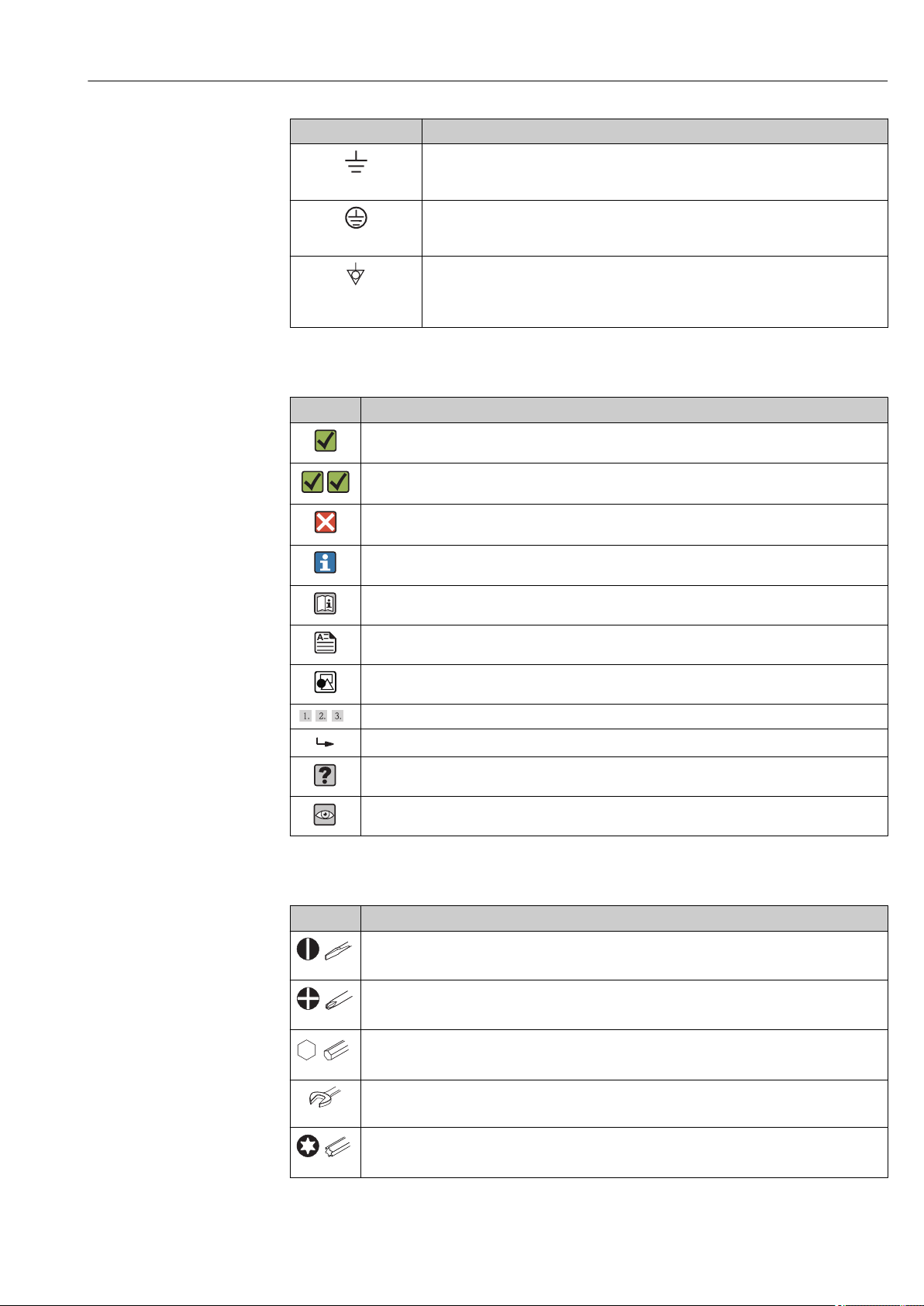
1.2.3 Symbols for certain types of information
Symbol Meaning
Permitted
Procedures, processes or actions that are permitted.
Preferred
Procedures, processes or actions that are preferred.
Forbidden
Procedures, processes or actions that are forbidden.
Tip
Indicates additional information.
Reference to documentation
Reference to page
Reference to graphic
Series of steps
Result of a step
Help in the event of a problem
Visual inspection
1.2.4 Tool symbols
Symbol Meaning
Flat-blade screwdriver
A0011220
Phillips screwdriver
A0011219
Allen key
A0011221
Open-ended wrench
A0011222
Torx screwdriver
A0013442
Endress+Hauser 5
Page 6

Important document information iTEMP TMT162
1.3 Documentation
Document Purpose and content of the document
Technical Information
TI01344T/09
Brief Operating Instructions
KA00250R/09
Functional safety manual (SIL)
SD01632T/09
The document types listed are available:
In the Download Area of the Endress+Hauser Internet site: www.endress.com →
Downloads
Planning aid for your device
The document contains all the technical data on the device and provides
an overview of the accessories and other products that can be ordered for
the device.
Guide that takes you quickly to the 1st measured value
The Brief Operating Instructions contain all the essential information
from incoming acceptance to initial commissioning.
Functional Safety Manual
This manual applies in addition to the Operating Instructions, Technical
Information and ATEX Safety Instructions. The requirements specific for
the protection function are described in this Safety Manual.
1.4 Registered trademarks
HART®
Registered trademark of the HART® FieldComm Group
6 Endress+Hauser
Page 7

iTEMP TMT162 Basic safety instructions
2 Basic safety instructions
2.1 Requirements for the personnel
NOTICE
The personnel for installation, commissioning, diagnostics and maintenance must
fulfill the following requirements:
Trained, qualified specialists must have a relevant qualification for this specific function
‣
and task
Are authorized by the plant owner/operator
‣
Are familiar with federal/national regulations
‣
Before beginning work, the specialist staff must have read and understood the
‣
instructions in the Operating Instructions and supplementary documentation as well as
in the certificates (depending on the application)
Following instructions and basic conditions
‣
The operating personnel must fulfill the following requirements:
Being instructed and authorized according to the requirements of the task by the
‣
facility's owner-operator
Following the instructions in these Operating Instructions
‣
2.2 Designated use
The device is a universal and configurable temperature field transmitter with either one or
two temperature sensor inputs for resistance thermometers (RTD), thermocouples (TC)
and resistance and voltage transmitters. The unit is designed for mounting in the field.
The manufacturer is not liable for damage caused by improper or non-designated use.
2.3 Workplace safety
For work on and with the device:
Wear the required personal protective equipment according to federal/national
‣
regulations.
2.4
CAUTION
L
Risk of injury!
Operate the device in proper technical condition and fail-safe condition only.
‣
The operator is responsible for interference-free operation of the device.
‣
Power supply
The device must only be powered by a 11.5 to 42 VDC voltage supply according to NEC
‣
class 02 (low voltage / current) with short circuit power limitation to 8 A / 150 VA.
Operational safety
Conversions to the device
Unauthorized modifications to the device are not permitted and can lead to unforeseeable
dangers.
If, despite this, modifications are required, consult with Endress+Hauser.
‣
Repair
To ensure continued operational safety and reliability:
Carry out repairs on the device only if they are expressly permitted.
‣
Observe federal/national regulations pertaining to repair of an electrical device.
‣
Endress+Hauser 7
Page 8

Basic safety instructions iTEMP TMT162
Use original spare parts and accessories from Endress+Hauser only.
‣
Hazardous area
To eliminate a danger for persons or for the facility when the device is used in the
hazardous area (e.g. explosion protection or safety equipment):
Based on the technical data on the nameplate, check whether the ordered device is
‣
permitted for the intended use in the hazardous area. The nameplate can be found on
the side of the transmitter housing.
Observe the specifications in the separate supplementary documentation that is an
‣
integral part of these Instructions.
Electromagnetic compatibility
The measuring system complies with the general safety requirements in accordance with
EN 61010-1, the EMC requirements of IEC/EN 61326 and NAMUR Recommendation NE
21 and NE 89.
2.5
This measuring device is designed in accordance with good engineering practice to meet
state-of-the-art safety requirements, has been tested, and left the factory in a condition in
which it is safe to operate.
It meets general safety standards and legal requirements. It also complies with the EC
directives listed in the device-specific EC Declaration of Conformity. Endress+Hauser
confirms this by affixing the CE mark to the device.
2.6
We only provide a warranty if the device is installed and used as described in the
Operating Instructions. The device is equipped with security mechanisms to protect it
against any inadvertent changes to the device settings.
IT security measures in line with operators' security standards and designed to provide
additional protection for the device and device data transfer must be implemented by the
operators themselves.
Product safety
IT security
8 Endress+Hauser
Page 9
iTEMP TMT162 Incoming acceptance and product identification
DELIVERYNOTE
TMT162
0
1
2
3 Incoming acceptance and product
identification
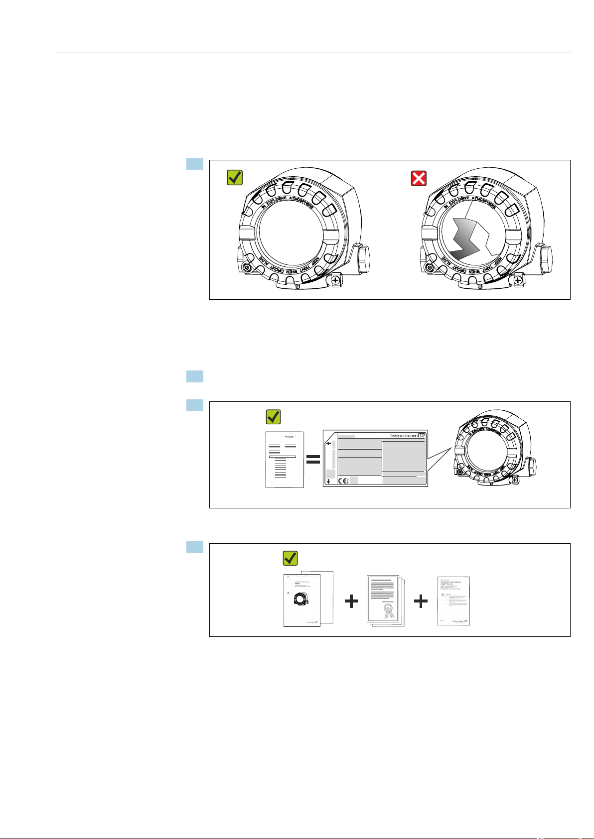
3.1 Incoming acceptance
1.
A0024856
Unpack the temperature transmitter carefully. Is the packaging or content damaged?
Damaged components may not be installed as the manufacturer can otherwise
not guarantee compliance with the original safety requirements or the material
resistance, and can therefore not be held responsible for any resulting damage.
2. Is the delivery complete or is anything missing? Check the scope of delivery against
your order.
3.
Does the nameplate match the ordering information on the delivery note?
4.
Are the technical documentation and all other necessary documents provided?
3.2 Product identification
The following options are available for identification of the device:
• Nameplate specifications
• Enter the serial number from the nameplate in the W@M Device Viewer
(www.endress.com/deviceviewer): All data relating to the device and an overview of
the Technical Documentation supplied with the device are displayed.
Endress+Hauser 9
A0024857
A0024858
Page 10

Incoming acceptance and product identification iTEMP TMT162
1
2
3
4
5
Install per XA00032R/09/a3/xx.yy
II2D Ex tb IIIC T110°C Db
Do not open when energized
11.5...40 V
4...20 mA HART
TMT162-
Ta=
-50 ...+55/70/85 °C T6/T5/T4 (-40...+75 °C SIL)
87484 Nesselwang
Made in Germany 2017
TMT162-SIL
IP66/67 TYPE4X Encl.
Current cosum.: 23 mA
0123456789
Ser.No.:
TAG No.: 0123456789ABCDEF
0123456789ABCDEF
Order Code:
Extended order code:
6
Threads M20x1.5
0044
3.2.1 Nameplate
Is this the correct device?
Check the data on the nameplate of the device and compare them against the requirements
of the measuring point:
1
Order code, serial number and TAG of device
2 Power supply, degree of protection, etc.
3 Ambient temperature range
4 Approvals in hazardous area with numbers of the
relevant Ex documentation (XA...)
5 Approvals with symbols
6 Device revision and firmware version
A0034479
1 Nameplate of the field transmitter
(example, Ex version)
3.2.2 Scope of delivery
The scope of delivery of the device comprises:
•
Temperature transmitter
Wall or pipe mounting bracket, optional
•
•
Dummy plugs
• Hard copy of multi-language Brief Operating Instructions
• Additional documentation for devices which are suitable for use in the hazardous area
(0
1), such as Safety Instructions (XA), Control or Installation Drawings (ZD).
• Hard copy of Functional Safety Manual (if SIL mode option selected)
3.2.3 Certificates and approvals
An overview of other approvals and certifications is provided in the "Technical data" section
→ 60
CE mark
The product meets the requirements of the harmonized European standards. As such, it
complies with the legal specifications of the EC directives. The manufacturer confirms
successful testing of the product by affixing to it the CE-mark.
EAC mark
The product meets the legal requirements of the EEU guidelines. The manufacturer
confirms the successful testing of the product by affixing the EAC mark.
UL approval
10 Endress+Hauser
UL recognized component (see www.ul.com/database, search for Keyword "E225237")
Page 11

iTEMP TMT162 Incoming acceptance and product identification
HART® protocol certification
The temperature transmitter is registered by the HART® FieldComm Group. The device
meets the requirements of the HART Communication Protocol Specifications, Revision 7
(HCF 7.6).
3.3 Transport and storage
Carefully remove all the packaging material and protective covers that are part of the
transported package.
Dimensions and operating conditions: → 59
Pack the device so that it is reliably protected against impact when it is stored (and
transported). The original packaging offers the best protection.
Storage temperature Without display –40 to +100 °C (–40 to +212 °F)
With display –40 to +80 °C (–40 to +176 °F)
Endress+Hauser 11
Page 12

Installation iTEMP TMT162
1
2 3 4 5
6
K
E
E
P
T
I
G
H
T
W
H
E
N
C
I
R
C
U
I
T
A
L
I
V
E
I
N
E
X
P
L
O
S
I
V
E
A
T
M
O
S
P
H
E
R
E
aaa
bbb
4 Installation
If stable sensors are used, the device can be fitted directly to the sensor. For remote
mounting to a wall or stand pipe, two mounting brackets are available. The illuminated
display can be mounted in four different positions.
4.1
Installation conditions
4.1.1 Dimensions
The dimensions of the device are provided in the "Technical data" section.→ 59
4.1.2
Installation point
Information about the conditions (such as the ambient temperature, degree of protection,
climate class etc.) that must be present at the installation point so that the device can be
mounted correctly is provided in the "Technical data" section.
When using in hazardous areas, the limit values of the certificates and approvals must be
observed (see Ex Safety Instructions).
4.2 Mounting the transmitter
NOTICE
Do not overtighten the mounting screws, as this could damage the field transmitter.
Maximum torque = 6 Nm (4.43 lbf ft)
‣
4.2.1 Direct sensor mounting
2 Direct field transmitter mounting on sensor
Thermowell
1
2 Insert
3 Neck tube nipple and adapter
4 Sensor cables
5 Fieldbus cables
6 Fieldbus shielded cable
1. Mount the thermowell and screw down (1).
2. Screw the insert with the neck tube nipple and adapter into the transmitter (2). Seal
the nipple and adapter thread with silicone tape.
3. Connect the sensor cables (4) to the terminals for the sensors, see the terminal
assignment.
4. Fit the field transmitter with the insert on the thermowell (1).
5. Mount the fieldbus shielded cable or fieldbus connector (6) on the other cable gland.
12 Endress+Hauser
A0024817
Page 13

iTEMP TMT162 Installation
1
3
2
25 (0.98)
180
(7.1)
160
(6.3)
!51
(2.01)
M10
10.5
(0.41)
72 (2.8)
72 (2.8)
56
(2.2)
M10
M10
≤ 50
(1.97)
6. Guide the fieldbus cables (5) through the cable gland of the fieldbus transmitter
housing into the connection compartment.
7. Screw the cable gland tight as described in the Ensuring the degree of protection
section→ 20. The cable gland must meet explosion protection requirements.
4.2.2 Remote mounting
3 Installation of the field transmitter using the mounting bracket, see chapter 'Accessories'. Dimensions in
mm (in)
Mounting with combined wall/pipe mounting bracket
1
2 Mounting with pipe mounting bracket 2"/V4A
3 Mounting with wall mounting bracket
A0027188
Endress+Hauser 13
Page 14

Installation iTEMP TMT162
1
2
3
4
90°
90°
90°
90°
3 mm
WRITE
LOCK
ON
OFF
Proof-
Test
4.3 Display mounting
A0025417
4 4 display installation positions, attachable in 90° stages
Cover clamp
1
2 Housing cover with O-ring
3 Display with fitting kit and twist protection
4 Electronics module
1. Remove the cover clamp (1).
2. Unscrew the housing cover together with the O-ring (2).
3. Remove the display with twist protection (3) from the electronics module (4). Fit the
display with the fitting kit in the desired position in 90° stages and plug it into the
correct slot on the electronics module.
4. Then screw the housing cover together with the O-ring.
5. Fit the cover clamp (1) back on.
4.4 Post-installation check
After installing the device, always run the following final checks:
Device condition and specifications Notes
Is the device undamaged (visual inspection)? -
Do the ambient conditions match the device specification (e.g. ambient temperature,
measuring range, etc.)?
→ 46
14 Endress+Hauser
Page 15

iTEMP TMT162 Wiring
5 Wiring
5.1 Connection conditions
CAUTION
L
The electronics could be destroyed
Switch off power supply before installing or connecting the device. Failure to observe
‣
this may result in destruction of parts of the electronics.
When connecting Ex-certified devices, please take special note of the instructions and
‣
connection schematics in the Ex-specific supplement to these Operating Instructions.
Contact the supplier if you have any questions.
A Phillips head screwdriver is required to wire the field transmitter at the terminals.
NOTICE
Do not overtighten the screw terminals, as this could damage the transmitter.
Maximum torque = 1 Nm (³⁄₄ lbf ft).
‣
Proceed as follows to wire the device:
1. Remove the cover clamp. → 24
2. Unscrew the housing cover on the connection compartment together with the O-ring.
→ 24. The connection compartment is opposite the electronics module.
3. Open the cable glands of the device.
4. Route the appropriate connecting cables through the openings of the cable glands.
5. Wire the cables in accordance with → 5, 16 and as described in the sections:
"Connecting the sensor" → 15 and "Connecting the measuring device" → 17.
On completion of the wiring, screw the screw terminals tight. Tighten the cable glands
again. Refer to the information provided in the 'Ensuring the degree of protection' section.
Screw the housing cover tight again and fit the cover clamp back on. → 24
In order to avoid connection errors always follow the instructions in the post-connection
check section before commissioning!
5.2 Connecting the sensor
NOTICE
ESD - electrostatic discharge. Protect the terminals from electrostatic discharge.
‣
Failure to observe this may result in destruction or malfunction of parts of the
electronics.
Endress+Hauser 15
Page 16

Wiring iTEMP TMT162
3
3
3
3
3
3
1
1
1
1
1
1
1
4
4
2
2
2
2
2
R
TD
RTD
RTD
Ω
5
5
5
6
6
6
6
RTD
RTD
6
4
4
4
4
T
C
TC
Ω Ω
ΩΩ
+
-
1
2
3
4
5
6
-
+
3
S2
-
+
-
3
4
S1
4-wire
2-wire 3-wire
Bus connection and
supply voltage
Sensor 1
Sensor 2
Sensor 1
Sensor 2
Terminal assignment
5 Wiring the field transmitter
NOTICE
When connecting 2 sensors ensure that there is no galvanic connection between the
sensors (e.g. caused by sensor elements that are not isolated from the thermowell).
The resulting equalizing currents distort the measurements considerably.
The sensors must remain galvanically isolated from one another by connecting each
‣
sensor separately to a transmitter. The transmitter provides sufficient galvanic isolation
(> 2 kV AC) between the input and output.
The following connection combinations are possible when both sensor inputs are assigned:
Sensor input 2
RTD or resistance
transmitter, two-wire
RTD or resistance
transmitter, threewire
RTD or resistance
transmitter, four-wire
Thermocouple (TC),
voltage transmitter
transmitter,
Sensor input 1
RTD or
resistance
two-wire
-
-
- - - -
RTD or
resistance
transmitter,
three-wire
RTD or
resistance
transmitter,
four-wire
A0024515-EN
Thermocouple
(TC), voltage
transmitter
16 Endress+Hauser
Page 17

iTEMP TMT162 Wiring
+
-
1
2
3
4
5
6
+
-
3
4
+
-
3
1
2
3
4
!
!
5.3 Connecting the measuring device
5.3.1
CAUTION
L
Cable glands or entries
Risk of damage
Switch off power supply before installing or connecting the device. Failure to observe
‣
this may result in destruction of parts of the electronics.
If the device has not been grounded as a result of the housing being installed, we
‣
recommended grounding it via one of the ground screws. Observe the grounding
concept of the plant! Keep the cable shield between the stripped fieldbus cable and the
ground terminal as short as possible! Connection of the functional grounding may be
needed for functional purposes. Compliance with the electrical codes of individual
countries is mandatory.
If the shielding of the fieldbus cable is grounded at more than one point in systems that
‣
do not have additional potential equalization, mains frequency equalizing currents can
occur that damage the cable or the shielding. In such cases the shielding of the fieldbus
cable is to be grounded on one side only, i.e. it must not be connected to the ground
terminal of the housing. The shield that is not connected should be insulated!
• The terminals for the fieldbus connection have integrated polarity protection.
• Cable cross-section: max. 2.5 mm²
• A shielded cable must be used for the connection.
Follow the general procedure. → 15.
6 Connecting the device to the fieldbus cable
1
Fieldbus terminals - fieldbus communication and power supply
2 Shielded fieldbus cable
3 Ground terminals, internal
4 Ground terminal (external, relevant for remote version)
5.3.2 Connecting the HART® communication resistor
If the HART® communication resistor is not integrated into the power supply unit, it is
necessary to incorporate a communication resistor of 250 Ω into the 2-wire cable. For
the connection, also refer to the documentation published by the HART® FieldComm
Group, particularly HCF LIT 20: “HART, a technical summary”.
Endress+Hauser 17
A0010823
Page 18

Wiring iTEMP TMT162
Commubox
1
2
3
4
5
6
+
-
1
2
3
4
5
6
+
-
3
4
+
-
3
PMC731: PIC0001
Online
1 >Group Select
2 PV 0.7 bar
HELP
SEND
HOME
1
2
3
4
5
6
³ 250 W
Commubox
PMC731: PIC0001
Online
1 >Group Select
2 PV 0.7 bar
HELP
SEND
HOME
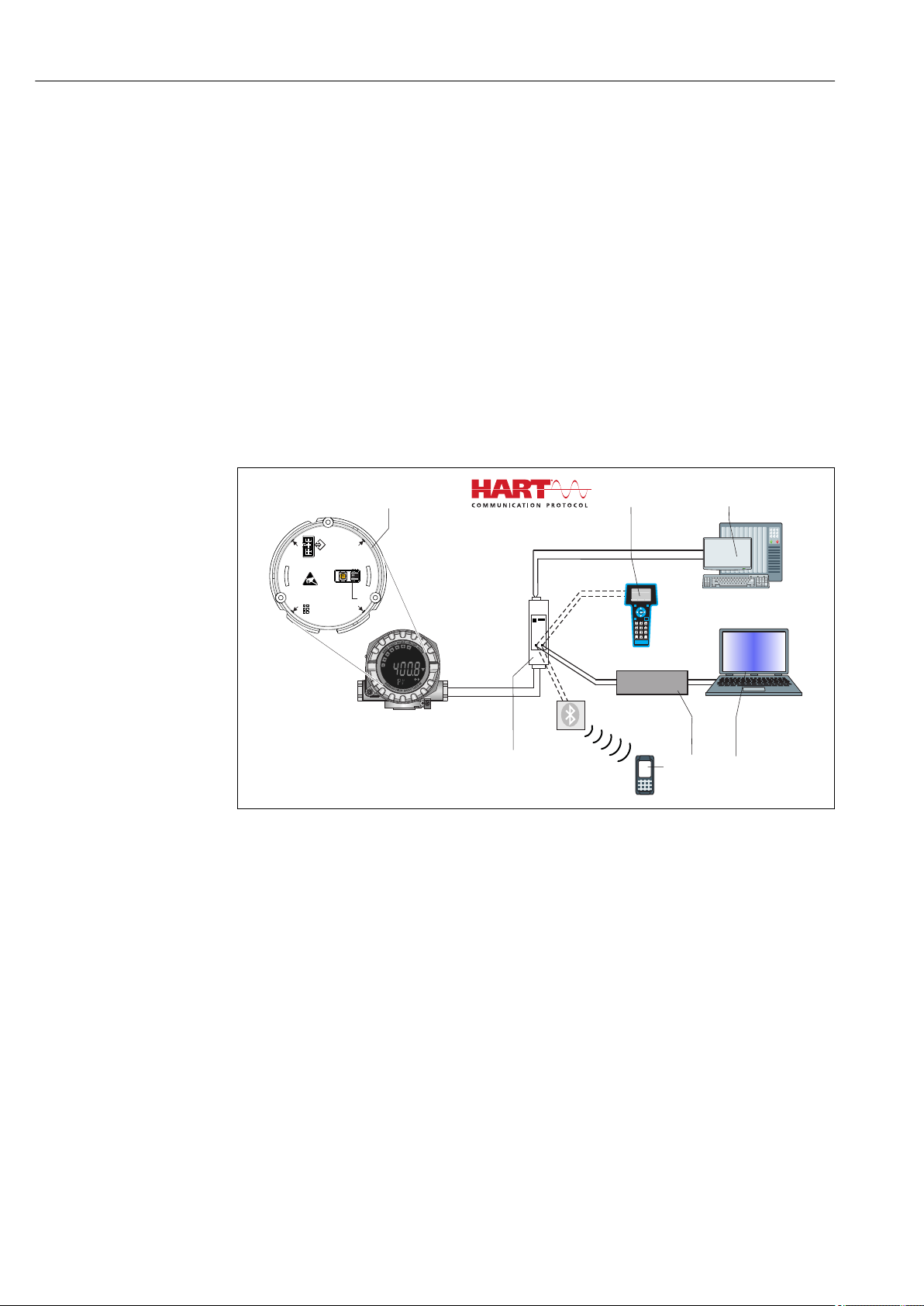
A0033548
7 HART® connection with Endress+Hauser power supply unit, including integrated communication resistor
Temperature field transmitter
1
2 HART® handheld communicator
3 PLC/DCS
4 Configuration software, e.g. FieldCare
5 Configuration via Field Xpert SFX350/370
6 Power supply unit, e.g. RN221 from Endress+Hauser
8 HART® connection with other power supply units that do not have a built-in HART® communication
resistor
1
Temperature field transmitter
2 HART® communication resistor
3 PLC/DCS
4 Configuration software, e.g. FieldCare
5 HART® handheld communicator
6 Configuration via Field Xpert SFX350/370
5.3.3 Shielding and grounding
The specifications of the HART FieldComm Group must be observed during installation.
18 Endress+Hauser
A0033549
Page 19
iTEMP TMT162 Wiring
1
2
3
4
4
+
-
1
2
3
5
6
+
-
3
4
S1
3
S2
-
+
+
-
!
+
Sensor 2
Sensor 1
-
Bus connection and
supply voltage
A0010984
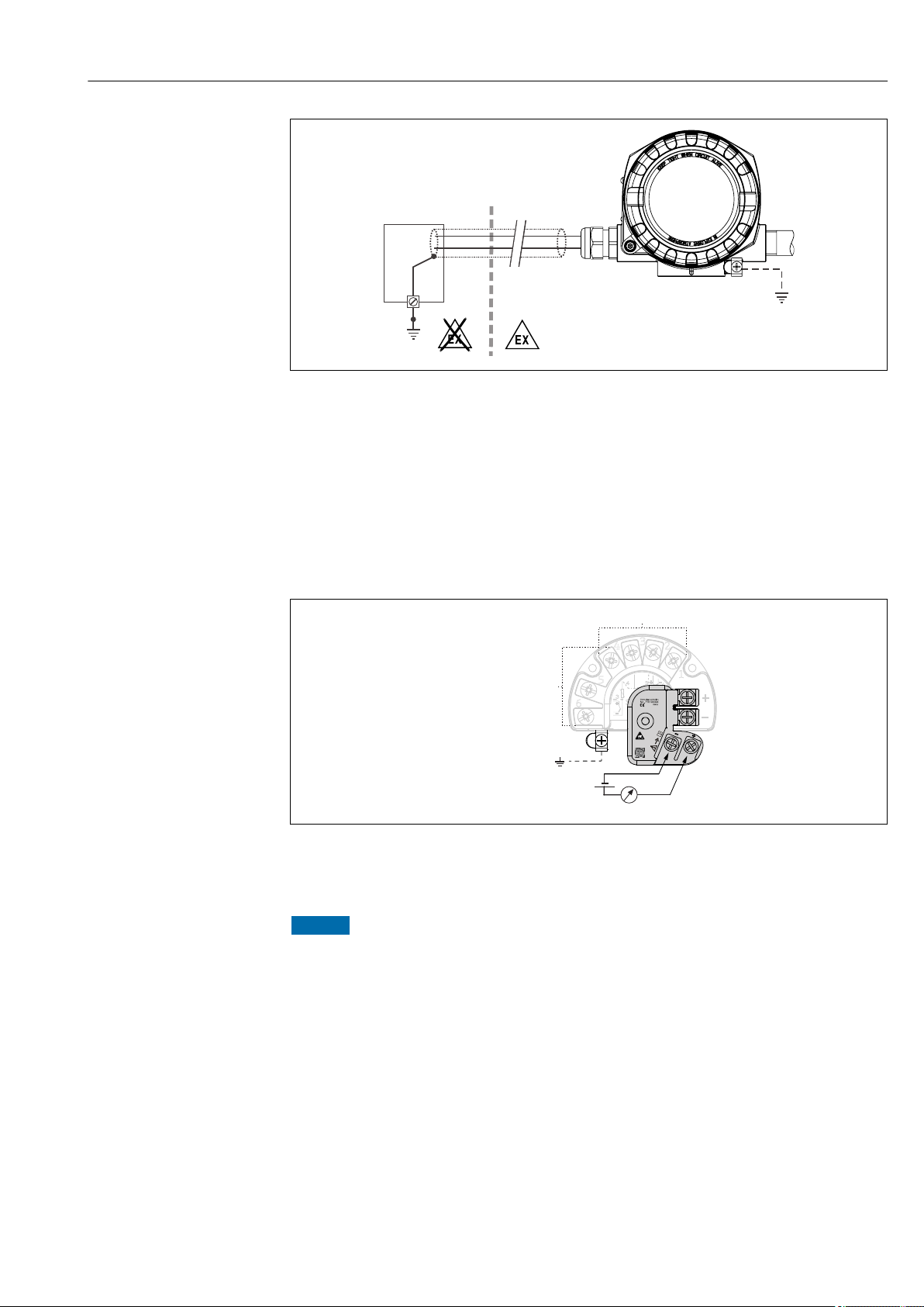
9 Shielding and grounding the signal cable at one end with HART® communication
Supply unit
1
2 Grounding point for HART® communication cable shield
3 Grounding of the cable shield at one end
4 Optional grounding of the field device, isolated from cable shielding
5.4 Special connection instructions
If the device is fitted with a surge arrester module, the bus is connected and the power is
supplied via the screw terminals on the surge arrester module.
A0033027-EN
10 Electrical connection of surge arrester
5.4.1
NOTICE
To perform the function test on the surge arrester module correctly:
Remove the surge arrester module before performing the test.
‣
To do so, release screws (1) and (2) with a screwdriver as well as securing screw (3)
‣
with an allen key.
The surge arrester module can be lifted off easily.
‣
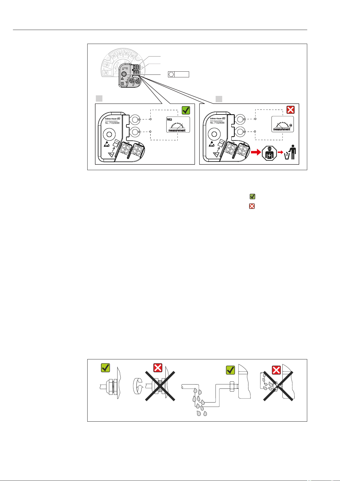
Perform the function test as shown in the following graphic.
‣
Surge arrester function test
Endress+Hauser 19
Page 20
Wiring iTEMP TMT162
1.
2.
4
+
-
1
2
3
5
6
+
-
3
4
S1
3
S2
-
+
+
-
!
1
2
3
3 mm
A0033829
11 Surge arrester function test
Ohmmeter in high-impedance range = surge arrester working .
Ohmmeter in low-impedance range = surge arrester defective . Notify Endress
+Hauser Service. Dispose of the defective surge arrester module as electronic waste.
For information on device disposal, see the Operating Instructions for the device.
→ 43
5.5 Ensuring the degree of protection
The measuring system meets all the requirements of IP67 protection. Compliance with the
following points is mandatory following installation in the field or servicing in order to
ensure that IP67 protection is maintained:
•
The housing seals must be clean and undamaged when inserted into their grooves. The
seals must be dried, cleaned or replaced if necessary.
• All housing screws and screw caps must be firmly tightened.
• The cables used for connection must be of the specified outside diameter (e.g. M20x1.5,
cable diameter 8 to 12 mm).
• Firmly tighten the cable gland. → 12, 20
• The cables must loop down before they enter the cable glands ("water trap"). This means
that any moisture that may form cannot enter the gland. Install the device so that the
cable glands are not facing upwards. → 12, 20
• Cable glands not used are to be blanked off using the dummy plugs provided.
• Do not remove the grommet from the cable gland.
12Connection tips to retain IP67 protection
20 Endress+Hauser
A0024523
Page 21
iTEMP TMT162 Wiring
5.6 Post-connection check
Device condition and specifications Notes
Is the device or cable undamaged (visual inspection)? --
Electrical connection Notes
Does the supply voltage match the specifications on
the nameplate?
Do the mounted cables have adequate strain relief? Visual inspection
Are the power supply and signal cables correctly
connected?
Are all the screws terminals sufficiently tightened? → 15
Are all the cable entries installed, tightened and
sealed?
Are all the housing covers installed and tightened? → 24
Standard mode and SIL mode: U = 11.5 to 42 V
→ 17
→ 20
DC
Endress+Hauser 21
Page 22
Operating options iTEMP TMT162
°C
WRITE
LOCK
ON
OFF
PMC731: PIC0001
Online
1 >Group Select
2 PV 0.7 bar
Commubox
2
3
4
5
7
1
Proof-
Test
6
HELP
SEND
HOME
6 Operating options
6.1 Overview of operation options
Operators have a number of options for configuring and commissioning the device:
• Configuration software → 27
HART® functions and device-specific parameters are primarily configured via the
Fieldbus interface. Special configuration and operating programs are available from
various manufacturers for this purpose.
• Miniature switch (DIP switch) and proof-test button for various hardware settings
–
Hardware write protection is activated and deactivated via a miniature switch (DIP
switch) on the electronics module.
– Proof-test button for testing in SIL mode without HART operation. Pressing the button
triggers a device restart. The proof test checks the functional integrity of the
transmitter in the SIL mode during commissioning, in the event of changes to safetyrelated parameters or generally at appropriate intervals.
A0024548
13 Operating options of device
Hardware settings via DIP switch and proof-test button
1
2 HART® handheld communicator
3 PLC/DCS
4 Configuration software, e.g. FieldCare
5 Commubox: Power supply and modem for field devices with HART® protocol
6 Configuration via Field Xpert SFX350/370
7 Power supply unit and active barrier, .e.g. RN221 from Endress+Hauser
22 Endress+Hauser
Page 23
iTEMP TMT162 Operating options
°C
°F
%
K
10
0
20
30
40
50
60
70
80
90
100
!
1
2
3
4
5
6
7
6.1.1 Display and operating elements
Display elements
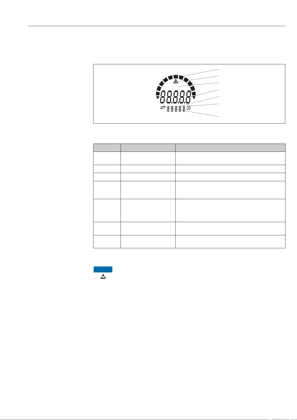
A0034101
14 LC display of the field transmitter (backlit, attachable in 90° stages)
Item No. Function Description
1 Bar graph display In increments of 10% with indicators for underranging and
overranging.
2 'Caution' symbol This is displayed when an error or warning occurs.
3 Unit display K, °F, °C or % Unit display for the internal measured value displayed.
4 Measured value display, digit
height
20.5 mm
5 Status and information
display
6 'Configuration locked' symbol
7 'Communication' symbol
Displays the current measured value. In the event of an error
or warning, the corresponding diagnostics information is
displayed. → 36
Indicates which value is currently shown on the display. Text
can be entered for every value. In the event of an error or a
warning, the sensor input that triggered the error/warning is
also displayed where applicable, e.g. SENS1
The 'configuration locked' symbol appears when configuration
is locked via the hardware or software
The communication symbol appears when HART®
communication is active.
Local operation
NOTICE
ESD - electrostatic discharge. Protect the terminals from electrostatic discharge.
‣
Failure to observe this may result in destruction or malfunction of parts of the
electronics.
Hardware write protection and the proof test can be activated via a DIP switch or button on
the electronics module. When write protection is active, parameters cannot be modified. A
key symbol on the display indicates that the write protection is on. Write protection
prevents any write access to the parameters.
Endress+Hauser 23
Page 24

Operating options iTEMP TMT162
3 mm
1.
2.
3.
4.
5.
WRITE
LOCK
ON
OFF
Proof-
Test
A0033847
Procedure for setting the DIP switch or activating the proof test:
1. Remove the cover clamp.
2. Unscrew the housing cover together with the O-ring.
3. If necessary, remove the display with the fitting kit from the electronics module.
4. Configure the hardware write protection WRITE LOCK accordingly using the DIP
switch. In general, the following applies: switch to ON = function enabled, switch to
OFF = function disabled.
5. If performing a SIL commissioning test and a proof test, make a device restart using
the button.
Once the hardware setting has been made, re-assemble the housing cover in the reverse
order.
24 Endress+Hauser
Page 25
iTEMP TMT162 Operating options
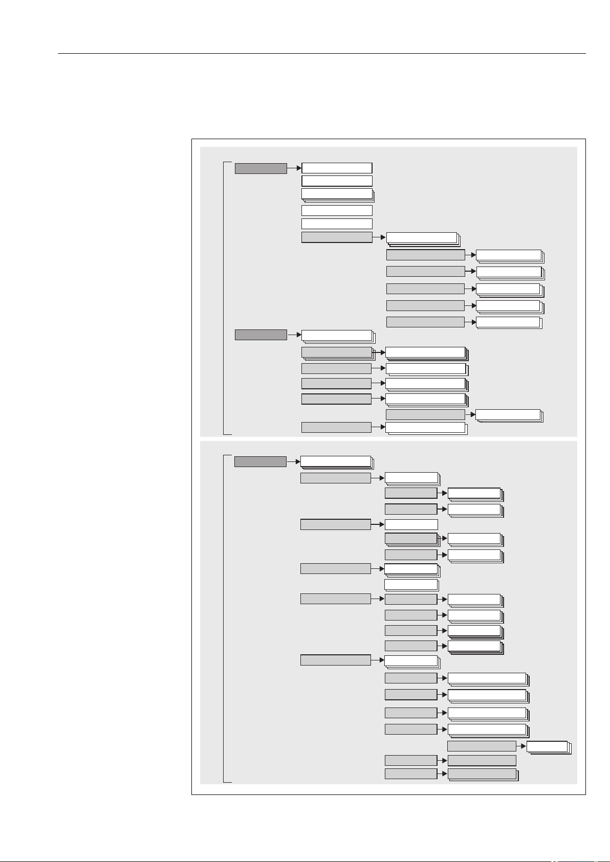
Expert
System
Sensors
Communication
Diagnostics
Operating menu for experts
D
intervalisplay
Setup
Advanced setup
Device tag
Diagnostics
Operating menu for operators and maintenances
Operator, maintenance
Expert
Output
Unit
Sensor type
Lower range value
Upper range value
Enter access code
Sensor
Sensor offset
Current output
Output current
Actual diagnostics
Diagnostics list
Device reset
Enter access code
Unit
Display
Display interval
Sensor Sensor type
Lower range v.
Current trim.
HART config.
HART info
HART output
Burst mode
Device type
Assign PV
Actual d .iagn
D stics listiagno
Actual d stics countiagno
Event logbook
Device information
Simulation
Previous diagnostics
Device tag
Min/max values
Sensor value
Measured values
SIL
SIL Option
Administration
Sensor Min
Display
Device tag
Device reset
Administration
D stics set.iagno
Sensor switch s.
Burst config.
Event logbook
Device info.
Sensor value
Simulation
Simulation diagn.
Previous diagnostics
Device tag
Measured val.
Min/max values
Sensor1 Min
Actual diagnostics count
Simulation
Meas. channels
Diagnostic set.
Diagnostic behavior
6.2 Structure and function of the operating menu
6.2.1
Structure of the operating menu
Endress+Hauser 25
A0033850-EN
Page 26

Operating options iTEMP TMT162
The configuration in the SIL mode is different from the configuration in the standard
mode. For more detailed information please refer to the Functional Safety Manual
(SD01632T/09).
Submenus and user roles
Certain parts of the menu are assigned to certain user roles. Each user role corresponds to
typical tasks within the lifecycle of the device.
User role Typical tasks Menu Content/meaning
Maintenance
Operator
Expert Tasks that require detailed knowledge of the function
Commissioning:
• Configuration of the measurement.
• Configuration of data processing (scaling,
linearization, etc.).
Configuration of the analog measured value output.
•
Tasks during operation:
• Configuration of the display.
• Reading measured values.
Fault elimination:
• Diagnosing and eliminating process errors.
• Interpretation of device error messages and
correcting associated errors.
of the device:
• Commissioning measurements under difficult
conditions.
• Optimal adaptation of the measurement to difficult
conditions.
• Detailed configuration of the communication
interface.
• Error diagnostics in difficult cases.
"Setup" Contains all parameters for commissioning:
• Setup parameters
Once values have been set for these parameters, the
measurement should generally be completely
configured.
• "Advanced setup" submenu
Contains additional submenus and parameters:
– For more accurate configuration of the
measurement (adaptation to special measuring
conditions).
– For converting the measured value (scaling,
linearization).
– For scaling the output signal.
– Required in ongoing operation: configuration of
the measured value display (displayed values,
display format, etc.).
"Diagnostics" Contains all parameters for detecting and analyzing
errors:
• Diagnostic list
Contains up to 3 currently active error messages.
• Event logbook
Contains the last 5 error messages (no longer active).
• "Device information" submenu
Contains information for identifying the device.
• "Measured values" submenu
Contains all current measured values.
• "Simulation" submenu
Used to simulate measured values, output values or
diagnostic messages.
• "Device reset" submenu
"Expert" Contains all parameters of the device (including those
that are already in one of the other menus). The
structure of this menu is based on the function blocks
of the device:
• "System" submenu
Contains all higher-level device parameters that do
not pertain either to measurement or the measured
value communication.
• "Sensor" submenu
Contains all parameters for configuring the
measurement.
• "Output" submenu
Contains all parameters for configuring the analog
current output.
• "Communication" submenu
Contains all parameters for configuring the digital
communication interface.
• "Diagnostics" submenu
Contains all parameters for detecting and analyzing
errors.
26 Endress+Hauser
Page 27
iTEMP TMT162 Operating options
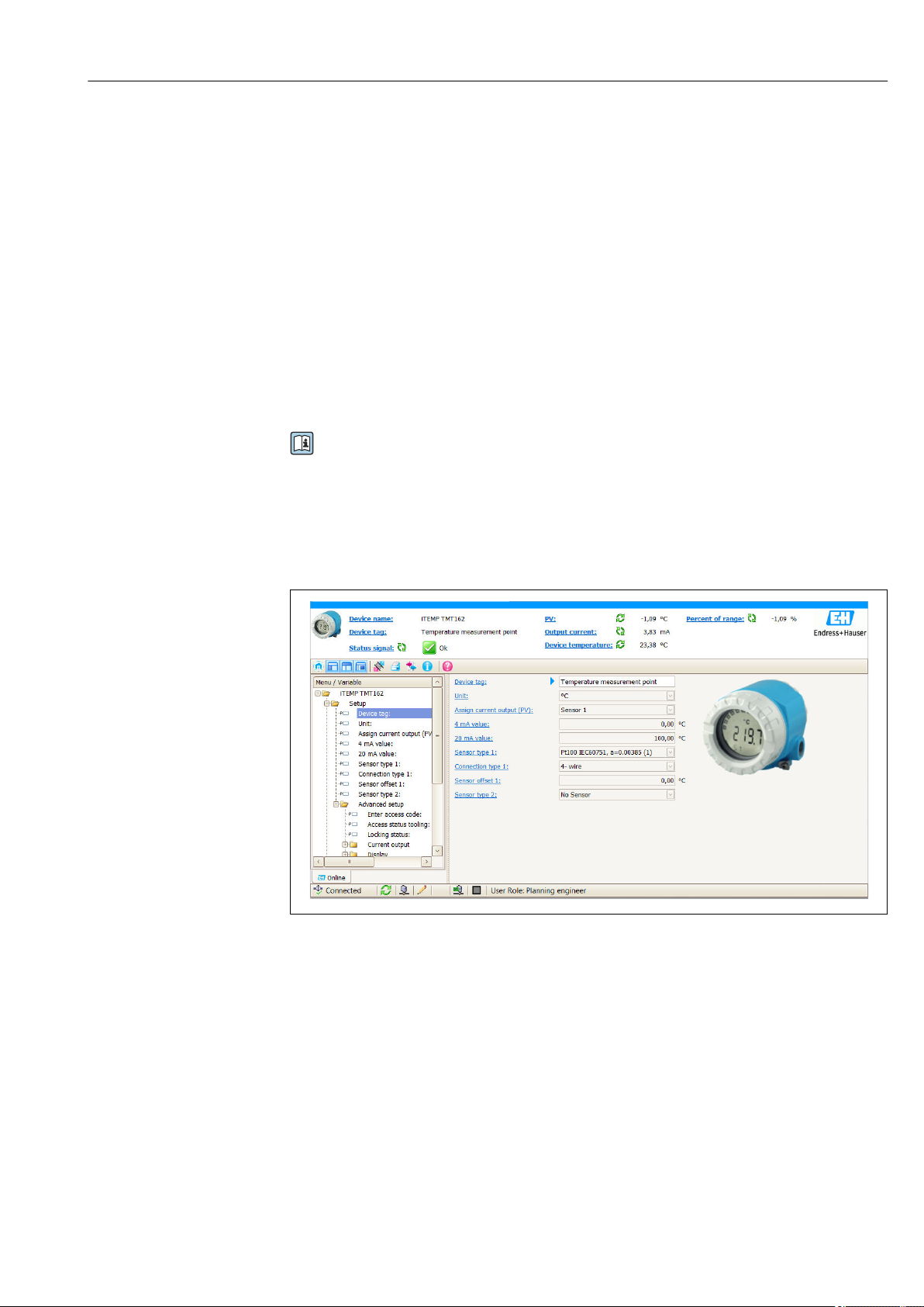
6.3 Access to the operating menu via the operating tool
6.3.1
Function range
FDT/DTM-based plant asset management tool from Endress+Hauser. It can configure all
smart field devices in a system and helps you manage them. By using the status
information, it is also a simple but effective way of checking their status and condition.
Access is via the HART® protocol or CDI (= Endress+Hauser Common Data Interface).
Typical functions:
• Parameterization of transmitters
•
Loading and saving device data (upload/download)
• Documentation of the measuring point
• Visualization of the measured value memory (line recorder) and event logbook
Source for device description files
See information → 29
User interface
FieldCare
For details, see Operating Instructions BA00027S/04/xx and BA00059AS/04/xx
A0033862-EN
6.3.2 DeviceCare
Function range
The fastest way to configure Endress+Hauser field devices is with the dedicated DeviceCare
tool. DeviceCare's user-friendly design enables transparent and intuitive device connection
and configuration. Intuitive menus and step-by-step instructions with status information
ensure optimum transparency.
Quick and easy to install, connects devices in a single click (one-click connection).
Automatic hardware identification and driver catalog update. The devices are configured
using DTMs (Device Type Manager). Multilingual support, the tool is touch-enabled for
tablet use. Hardware interfaces for modems : (USB/RS232), TCP/IP, USB and PCMCIA.
Endress+Hauser 27
Page 28

Operating options iTEMP TMT162
Source for device description files
See data → 29
6.3.3
Function range
Field Xpert is an industrial PDA with integrated touchscreen for commissioning and
maintaining field devices in explosion hazardous and safe areas. It enables the efficient
configuration of FOUNDATION fieldbus, HART and WirelessHART devices.
Communication is wireless via Bluetooth or WiFi interfaces.
Source for device description files
See data → 29
Field Xpert
6.3.4 AMS Device Manager
Function range
Program from Emerson Process Management for operating and configuring measuring
devices via the HART® protocol.
Source for device description files
See data → 29
6.3.5 SIMATIC PDM
Function range
SIMATIC PDM is a standardized, vendor-independent program from Siemens for the
operation, configuration, maintenance and diagnosis of smart field devices via the HART
protocol.
Source for device description files
See data → 29
6.3.6 Field Communicator 475
Function range
Industrial handheld terminal from Emerson Process Management for remote
configuration and measured value display via the HART ® protocol.
Source for device description files
See data → 29
®
28 Endress+Hauser
Page 29

iTEMP TMT162 System integration
7 System integration
Version data for the device
Firmware version 04.01.zz • On the title page of the Operating instructions
• On the nameplate
• Firmware version
Diagnostics → Device info→ Firmware Version
Manufacturer ID 0x0011 Manufacturer ID parameter
Diagnostics → Device info→ Manufacturer ID
Device type ID 0x11CE Device type parameter
Diagnostics → Device info → Device type
HART protocol revision 7.6 ---
Device revision 4 • On the transmitter nameplate
• Device revision parameter
Diagnostics → Device info → Device revision
The suitable device description file (DD or DTM) for the individual operating tools is listed
in the table below, along with information on where the file can be acquired.
parameter
Operating tools
Operating tool Sources for obtaining device descriptions (DD) or device type
managers (DTM)
FieldCare
(Endress+Hauser)
DeviceCare
(Endress+Hauser)
AMS Device Manager
(Emerson Process Management)
SIMATIC PDM
(Siemens)
Field Communicator 475
(Emerson Process Management)
FieldXpert SFX350, SFX370
(Endress+Hauser)
• www.endress.com → Download Area → Software
CD-ROM (contact Endress+Hauser)
•
• DVD (contact Endress+Hauser)
www.endress.com → Download Area → Software
Please ask the operating tool manufacturer for information on where to
obtain the DD/DTM.
Use update function of handheld terminal
Use update function of handheld terminal
7.1 HART device variables and measured values
The following measured values are assigned to the device variables at the factory:
Device variables for temperature measurement
Device variable Measured value
Primary device variable (PV) Sensor 1
Secondary device variable (SV) Device temperature
Tertiary device variable (TV) Sensor 1
Quaternary device variable (QV) Sensor 1
It is possible to change the assignment of device variables to process variables in the
Expert → Communication → HART output menu.
Endress+Hauser 29
Page 30
System integration iTEMP TMT162
7.2 Device variables and measured values
The following measured values are assigned to the individual device variables:
Device variable code Measured value
0 Sensor 1
1 Sensor 2
2 Device temperature
3 Average of sensor 1 and sensor 2
4 Difference between sensor 1 and sensor 2
5 Sensor 1 (backup sensor 2)
6 Sensor 1 with switchover to sensor 2 if a limit value is exceeded
7 Average of sensor 1 and sensor 2 with backup
The device variables can be queried by a HART® master using HART® command 9 or
33.
7.3
Supported HART® commands
The HART® protocol enables the transfer of measuring data and device data between
the HART® master and the field device for configuration and diagnostics purposes.
HART® masters such as the handheld terminal or PC-based operating programs (e.g.
FieldCare) need device description files (DD, DTM) which are used to access all the
information in a HART® device. This information is transmitted exclusively via
"commands".
There are three different types of command
•
Universal commands:
All HART® devices support and use universal commands. These are associated with the
following functionalities for example:
– Recognition of HART® devices
– Reading digital measured values
• Common practice commands:
Common practice commands offer functions which are supported and can be executed by
many but not all field devices.
• Device-specific commands:
These commands allow access to device-specific functions which are not HART
®
standard. Such commands access individual field device information, among other
things.
Command No. Designation
Universal commands
0, Cmd0 Read unique identifier
1, Cmd001 Read primary variable
2, Cmd002 Read loop current and percent of range
3, Cmd003 Read dynamic variables and loop current
6, Cmd006 Write polling address
7, Cmd007 Read loop configuration
8, Cmd008 Read dynamic variable classifications
9, Cmd009 Read device variables with status
11, Cmd011 Read unique identifier associated with TAG
30 Endress+Hauser
Page 31

iTEMP TMT162 System integration
Command No. Designation
12, Cmd012 Read message
13, Cmd013 Read TAG, descriptor, date
14, Cmd014 Read primary variable transducer information
15, Cmd015 Read device information
16, Cmd016 Read final assembly number
17, Cmd017 Write message
18, Cmd018 Write TAG, descriptor, date
19, Cmd019 Write final assembly number
20, Cmd020 Read long TAG (32-byte TAG)
21, Cmd021 Read unique identifier associated with long TAG
22, Cmd022 Write long TAG (32-byte TAG)
38, Cmd038 Reset configuration changed flag
48, Cmd048 Read additional device status
Common practice commands
33, Cmd033 Read device variables
34, Cmd034 Write primary variable damping value
35, Cmd035 Write primary variable range values
36, Cmd036 Set primary variable upper range value
37, Cmd037 Set primary variable lower range value
40, Cmd040 Enter/Exit fixed current mode
42, Cmd042 Perform device reset
44, Cmd044 Write primary variable units
45, Cmd045 Trim loop current zero
46, Cmd046 Trim loop current gain
50, Cmd050 Read dynamic variable assignments
51, Cmd051 Write dynamic variable assignments
54, Cmd054 Read device variable information
59, Cmd059 Write number of response preambles
72, Cmd072 Squawk
95, Cmd095 Read device communications statistics
100, Cmd100 Write primary variable alarm code
103, Cmd103 Write burst period
104, Cmd104 Write burst trigger
105, Cmd105 Read burst mode configuration
107, Cmd107 Write burst device variables
108, Cmd108 Write burst mode command number
109, Cmd109 Burst mode control
516, Cmd516 Read device location
517, Cmd517 Write device location
518, Cmd518 Read location description
519, Cmd519 Write location description
520, Cmd520 Read process unit tag
521, Cmd521 Write process unit tag
Endress+Hauser 31
Page 32

System integration iTEMP TMT162
Command No. Designation
523, Cmd523 Read condensed status mapping array
524, Cmd524 Write condensed status mapping
525, Cmd525 Reset condensed status map
526, Cmd526 Write status simulation mode
527, Cmd527 Simulate status bit
32 Endress+Hauser
Page 33

iTEMP TMT162 Commissioning
8 Commissioning
8.1 Post-installation check
Before commissioning the measuring point make sure that all final checks have been
carried out:
• "Post-installation check" checklist,
• "Post-connection check” checklist, → 15
8.2 Switching on the transmitter
Once the final checks have been successfully completed, it is time to switch on the supply
voltage. The transmitter performs a number of internal test functions after power-up. As
this procedure progresses, the following sequence of messages appears on the display:
Step Display
1 "Display" text and firmware version of the display
2 Firm logo
3 Device name (scrolling text)
4 Firmware, hardware version, device version and device address
5 For devices in SIL mode: SIL-CRC is displayed
6a Current measured value or
6b Current status message
If the switch-on procedure is not successful, the relevant diagnostic event, depending on the cause,
is displayed. A detailed list of diagnostic events and the corresponding troubleshooting instructions
can be found in the "Diagnostics and troubleshooting" section .
→ 12
The device operates in normal mode after approx. 30 seconds! Normal measuring mode
commences as soon as the switch-on procedure is completed. Measured values and status
values appear on the display.
8.3 Enabling configuration
If the device is locked and the parameter settings cannot be changed, it must first be
enabled via the hardware or software lock. The device is write-protected if the lock symbol
is shown on the display.
To unlock the device
• either switch the write protection switch on the electronics module to the "OFF" position
(hardware write protection), or
deactivate the software write protection via the operating tool. See the description for
•
the 'Define device write protection' parameter. → 83
When hardware write protection is active (write protection switch set to the "ON"
position), write protection cannot be disabled via the operating tool. Hardware write
protection must always be disabled before software write protection can be enabled or
disabled via the operating tool.
Endress+Hauser 33
Page 34

Diagnostics and troubleshooting iTEMP TMT162
9 Diagnostics and troubleshooting
9.1 Troubleshooting
Always start troubleshooting with the checklists below if faults occur after start up or
during operation. This takes you directly (via various queries) to the cause of the problem
and the appropriate remedial measures.
In the event of a serious fault, a device might have to be returned to the manufacturer
for repair. Refer to the "Return" section before returning the device to Endress+Hauser.
→ 43
Check display (local display)
Display is blank - no connection to
the HART host system.
Display is blank - however,
connection has been established to
the HART host system.
1. Check the supply voltage → terminals + and -
2. Measuring electronics defective → order spare part, → 41
1. Check whether the display module fitting kit is correctly seated on the
electronics module → 14
2. Display module defective → order spare part, →
3. Measuring electronics defective → order spare part, → 41
41
Local error messages on the display
→ 36
Faulty connection to the fieldbus host system
Problem Possible cause Solution
Device is not
responding.
Output current < 3.6mASignal line is not wired correctly. Check wiring.
HART
communication is
not working.
Supply voltage does not match the value
indicated on the nameplate.
Connecting cables are not in contact with
the terminals.
Electronics unit is defective. Replace the device.
Communication resistor missing or
incorrectly installed.
Commubox is connected incorrectly. Connect Commubox correctly.
Apply correct voltage
Check the connection of the cables and
correct if necessary.
Install the communication resistor (250 Ω)
correctly.
Error messages in the configuration software
→ 37
Application errors without status messages for RTD sensor connection
Problem Possible cause Solution
Measured value is incorrect/
inaccurate
Incorrect sensor orientation. Install the sensor correctly.
Heat conducted by sensor. Observe the face-to-face length of the
sensor.
34 Endress+Hauser
Page 35

iTEMP TMT162 Diagnostics and troubleshooting
Application errors without status messages for RTD sensor connection
Problem Possible cause Solution
Failure current (
≥ 21 mA)
≤ 3.6 mA or
Device programming is incorrect
(number of wires).
Device programming is incorrect
(scaling).
Incorrect RTD configured. Change the Sensor type device function.
Sensor connection. Check that the sensor is connected
The cable resistance of the sensor
(two-wire) was not compensated.
Offset incorrectly set. Check offset.
Faulty sensor. Check the sensor.
Incorrect sensor connection. Connect the connecting cables correctly
Device programming is incorrect (e.g.
number of wires).
Incorrect programming. Incorrect sensor type set in the Sensor
Change the Connection type device
function.
Change scaling.
correctly.
Compensate the cable resistance.
(terminal diagram).
Change the Connection type device
function.
type device function. Set the correct
sensor type.
Application errors without status messages for TC sensor connection
Problem Possible cause Solution
Incorrect sensor orientation. Install the sensor correctly.
Heat conducted by sensor. Observe the face-to-face length of the
sensor.
Measured value is incorrect/
inaccurate
Failure current (≤ 3.6 mA or
≥ 21 mA)
Device programming is incorrect
(scaling).
Incorrect thermocouple type (TC)
configured.
Incorrect comparison measuring
point set.
Interference via the thermocouple
wire welded in the thermowell
(interference voltage coupling).
Offset incorrectly set. Check offset.
Faulty sensor. Check the sensor.
Sensor is connected incorrectly. Connect the connecting cables correctly
Incorrect programming. Incorrect sensor type set in the Sensor
Change scaling.
Change the Sensor type device function.
Set the correct comparison measuring
point .
Use a sensor where the thermocouple
wire is not welded.
(terminal diagram).
type device function. Set the correct
sensor type.
Endress+Hauser 35
Page 36

Diagnostics and troubleshooting iTEMP TMT162
9.2 Diagnostic events
9.2.1
Displaying diagnostic events
NOTICE
Status signals and diagnostic behavior can be configured manually for certain
diagnostic events. If a diagnostic event occurs, however, it is not guaranteed that the
measured values are valid for the event and comply with the process for the status
signals S and M and the diagnostic behavior: 'Warning' and Disabled'.
Reset the status signal assignment to the factory setting.
‣
Status signals
Symbol Event
category
F Operating
error
C Service mode The device is in the service mode (during a simulation, for example).
S Out of
specification
M Maintenance
required
N Not
categorized
Meaning
An operating error has occurred.
The device is being operated outside its technical specifications (e.g. during
startup or cleaning).
Maintenance is required.
• If a valid measured value is not available, the display alternates between "- - -- -" and the
error message plus the defined error number and the ’’ symbol.
• If a valid measured value is present, the display alternates between the status plus the
defined error number (7-segment display) and the primary measured value (PV) with
the ’’ symbol.
Diagnostic behavior
Alarm Measurement is interrupted. The signal outputs assume the specified alarm
condition. A diagnostic message is generated.
Warning The device continues to measure. A diagnostic message is generated.
Disabled The diagnosis is completely disabled even if the device is not recording a measured
value.
36 Endress+Hauser
Page 37

iTEMP TMT162 Diagnostics and troubleshooting
Diagnostic event and event text
The fault can be identified by means of the diagnostic event. The event text helps you by
providing information on the fault.
Diagnostic event
Status signal Event number Event text
↓ ↓ ↓
Example F 042 Sensor corroded
3-digit number
If two or more diagnostic events are pending simultaneously, only the diagnostic message
with the highest priority is shown. Additional pending diagnostic messages are shown in
the Diagnostic list submenu → 85
. The status signal dictates the priority in which
the diagnostic messages are displayed. The following order of priority applies: F, C, S, M. If
two or more diagnostic events with the same status signal are active simultaneously, the
numerical order of the event number dictates the order of priority in which the events are
displayed, e.g.: F042 appears before F044 and before S044.
Past diagnostic messages that are no longer pending are shown in the Event logbook
submenu→ 86.
9.2.2
Overview of diagnostic events
Each diagnostic event is assigned a certain event behavior at the factory. The user can
change this assignment for certain diagnostic events.
Example:
Settings Device behavior
Configuration examples Diagnostic
number
1. Default setting 047 S Warning S Measured
2. Manual setting: status
signal S changed to F
3. Manual setting: Warning
diagnostic behavior changed
to Alarm
4. Manual setting: Warning
changed to Disabled
047 F Warning F Measured
047 S Alarm S Configured
047 S
Status
signal
1)
Diagnostic
behavior from
the factory
Disabled -
Status signal
(output via HART®
communication)
2)
Current
output
value
value
error current
Last valid
measured
value
PV, status Display
Measured value,
UNCERTAIN
Measured value,
UNCERTAIN
Measured value,
BAD
Last valid
3)
measured value,
GOOD
S047
F047
S047
S047
1) Setting is not relevant.
2) Status signal is not displayed.
3) The error current is output if no valid measured value is available.
The relevant sensor input for these diagnostic events can be identified with the
Actual diag channel parameter or on the display.
Endress+Hauser 37
Page 38

Diagnostics and troubleshooting iTEMP TMT162
Diagnosti
c
behavior
from the
factory
Diagnostic
number
Short text Corrective measure
Status
signal
from the
factory
Customizable
1)
Not
customizable
Diagnostics for the sensor
001 Device failure - sensor n
(sensor RJ)
041 Sensor interrupted - sensor n 1. Check electrical wiring.
3)
1. Restart device
F Alarm
2. Replace electronics
F Alarm
2. Replace sensor.
3. Check connection type.
042 Sensor n corroded 1. Check sensor.
M Warning
2. Replace sensor.
043 Short-circuit sensor n 1. Check electrical connection.
F Alarm
2. Check sensor.
3. Replace sensor or cable.
044 Sensor drift detected 1. Check sensor or main electronics.
M Warning
2. Replace sensor or main electronics.
047 Sensor limit reached sensor n
(sensor RJ)
048 Drift detection not possible 1. Check electrical connection.
1. Check sensor.
2. Check process conditions.
S Warning
M Warning
2. Check sensor.
3. Replace sensor.
062 Sensor connection faulty sensor
Check sensor connection. F Alarm
n (sensor RJ)
105 Calibration interval 1. Execute calibration and reset calibration
M Warning
interval.
2. Switch off calibration counter.
145 Compensation reference point
sensor n
1. Check terminal temperature.
2. Check external reference point.
F Alarm
Diagnostics for the electronics
201 Electronics faulty 1. Restart device.
F Alarm
2. Replace electronics.
221 Reference sensor defective
Replace device. M Alarm
sensor RJ
241 Firmware faulty 1. Restart device.
F Alarm
2. Power cycle device.
3. Replace electronics.
242 Firmware incompatible 1. Check firmware version.
F Alarm
2. Flash or replace main electronics.
261 Electronics module defective 1. Restart device.
F Alarm
2. Replace main electronics module.
283 Memory content inconsistent 1. Restart device.
F Alarm
2. Replace electronics.
286 Data storage inconsistent 1. Repeat safe parameterization.
F Alarm
2. Replace electronics.
Diagnostics for the configuration
401 Factory reset active Factory reset active, please wait. C Warning
Customizable
2)
Not
customizable
402 Initialization active sensor n
Initialization active, please wait. C Warning
(sensor RJ)
38 Endress+Hauser
Page 39

iTEMP TMT162 Diagnostics and troubleshooting
Diagnosti
c
behavior
from the
factory
Diagnostic
number
Short text Corrective measure
Status
signal
from the
factory
Customizable
1)
Not
customizable
410 Data transfer failed 1. Check connection.
2. Retry data transfer.
F Alarm
C
411 Up-/download active Up-/download active, please wait. Warning
412 Download active Download active, please wait C Warning
435 Linearization faulty sensor n
Check linearization. F Alarm
(sensor RJ)
438 Dataset different 1. Check data set file.
M Warning
2. Check device parameterization.
3. Download new device parameterization.
439 Data set Repeat the safe parameterization F Alarm
485 Process variable simulation
active sensor n (device
Deactivate simulation. C - Warning -
temperature)
491 Current output simulation
Deactivate simulation. C Warning
Customizable
2)
Not
customizable
495 Diagnostic event simulation
active
531 Factory adjustment missing
sensor n (current output)
537 Configuration sensor n (current
output)
Deactivate simulation. C Warning
1. Contact service.
F Alarm
2. Replace device.
1. Check device configuration
F Alarm
2. Upload and download new configuration.
(In case of current output: check
configuration of analog output.)
583 Input simulation sensor n Deactivate simulation.
C Warning
Diagnostics for the process
801 Supply voltage too low
825 Operating temperature 1. Check ambient temperature.
4)
Increase supply voltage. S Alarm
S Warning
2. Check process temperature.
844 Process value out of
specification-current output
1. Check process value.
2. Check application.
S Warning
Check sensor.
1) Can be set to F, C, S, M, N
2) Can be set to 'Alarm', 'Warning' and 'Disabled'
3) n = number of sensor inputs (1 and 2)
In the case of this diagnostic event, the device always outputs a "low" alarm status (output current ≤ 3.6 mA).
4)
Endress+Hauser 39
Page 40

Maintenance iTEMP TMT162
9.3 Software history and overview of compatibility
Revision history
The firmware version (FW) on the nameplate and in the Operating Instructions indicates
the device release: XX.YY.ZZ (example 01.02.01).
XX Change to main version. No longer compatible. The device and
Operating Instructions change.
YY Change to functions and operation. Compatible. The Operating
Instructions change.
ZZ Fixes and internal changes. No changes to the Operating Instructions.
Date Firmware
version
07/2017 04.01.zz HART protocol version 7.6 and addition of operating
Modification Documentation
BA01801T/09/en/01.17
parameters for functional safety (SIL3)
10 Maintenance
No special maintenance work is required for the temperature transmitter.
10.1
Endress+Hauser offers a wide variety of services for maintenance such as recalibration,
maintenance service or device tests.
Endress+Hauser services
Your Endress+Hauser Sales Center can provide detailed information on the services.
40 Endress+Hauser
Page 41

iTEMP TMT162 Repair
4
3
2
6
5
7
1
6
5
7
5
11 Repair
11.1 General notes
Repairs that are not described in these Operating Instructions must only be carried out
directly by the manufacturer or by the service department.
11.2 Spare parts
Spare parts currently available for the product can be found online at:
http://www.products.endress.com/spareparts_consumables. Always quote the serial
number of the device when ordering spare parts!
A0024557
15 Field transmitter spare parts
Item No. 1 Housing
Certificates:
A Non-hazardous area + Ex ia
B ATEX Ex d
Endress+Hauser 41
Material:
A Aluminum, HART 5
B Stainless steel 316L, HART 5
C T17, HART 5
F Aluminum, FF/PA
G Stainless steel 316L, FF/PA
H T17, FF/PA
K Aluminum, HART 7
L Stainless steel 316L, HART 7
M T17, HART 7
Page 42

Repair iTEMP TMT162
Item No. 1 Housing
Cable entry:
1 2 x thread NPT ½" + terminal block + 1 dummy plug
2 2 x thread M20x1.5 + terminal block + 1 dummy plug
4 2 x thread G ½" + terminal block + 1 dummy plug
Version:
A Standard
TMT162G- A ← order code
Item No. 4 Electronics
Certificates:
A Non-hazardous area
B ATEX Ex ia, FM IS, CSA IS
Sensor input; communication:
A 1x; HART 5, FW 01.03.zz, DevRev02
B 2x; HART 5, FW 01.03.zz, DevRev02, config. output sensor 1
C 2x; FOUNDATION Fieldbus Device Revision 1
D 2x; PROFIBUS PA, DevRev02
E 2x; FOUNDATION Fieldbus FW 01.01.zz, Device Revision 2
F 2x; FOUNDATION Fieldbus FW 02.00.zz, Device Revision 3
G 1x; HART7, Fw 04.01.zz, DevRev04
H 2x; HART7, Fw 04.01.zz, DevRev04, config. output sensor 1
Configuration:
A 50 Hz mains filter
B Produced as per original order (quote serial number) 50 Hz mains
filter
K 60 Hz mains filter
L Produced as per original order (quote serial number) 60 Hz mains
filter
TMT162E- ← order code
Item No. Order code Spare parts
2,3 TMT162X-DA Display HART 5 + fitting kit + twist protection
2,3 TMT162X-DB Display PA/FF + fitting kit + twist protection
2,3 TMT162X-DC Display fitting kit + twist protection
2,3 TMT162X-DD Display HART 7 + fitting kit + twist protection
5 TMT162X-HH Housing cover blind, aluminum Ex d, FM XP with seal, CSA approval, only
as cover of connection compartment
5 TMT162X-HI Housing cover blind, aluminum + seal
5 TMT162X-HK Housing cover cpl. display, aluminum Ex d with seal
5 TMT162X-HL Housing cover cpl. display, aluminum with seal
5 TMT162X-HA Housing cover blind, stainless steel 316L Ex d, ATEX Ex d, FM XP with
seal, CSA approval, only as cover of connection compartment
5 TMT162X-HB Housing cover blind, stainless steel 316L, with seal
5 TMT162X-HC Housing cover cpl. display, Ex d, stainless steel 316L, ATEX Ex d, FM XP,
CSA XP, with seal
42 Endress+Hauser
Page 43

iTEMP TMT162 Accessories
Item No. Order code Spare parts
5 TMT162X-HD Housing cover cpl. display, stainless steel 316L, with seal
5 TMT162X-HE Housing cover blind, T17, 316L
5 TMT162X-HF Housing cover cpl. display, polycarbonate, T17 316L
5 TMT162X-HG Housing cover cpl. display, glass, T17 316L
6 71158816 O-ring 88x3 EPDM70 PTFE slide coating
7 51004948 Cover clamp spare part set: screw, disk, spring washer
11.3 Return
The measuring device must be returned if it is need of repair or a factory calibration, or if
the wrong measuring device has been delivered or ordered. Legal specifications require
Endress+Hauser, as an ISO-certified company, to follow certain procedures when handling
products that are in contact with the medium.
To ensure safe, swift and professional device returns, please refer to the procedure and
conditions for returning devices provided on the Endress+Hauser website at
http://www.endress.com/support/return-material
11.4 Disposal
The device contains electronic components and must, therefore, be disposed of as
electronic waste in the event of disposal. Please pay particular attention to the local
regulations governing waste disposal in your country.
12
Accessories
Various accessories, which can be ordered with the device or subsequently from Endress
+Hauser, are available for the device. Detailed information on the order code in question is
available from your local Endress+Hauser sales center or on the product page of the
Endress+Hauser website: www.endress.com.
Always quote the serial number of the device when ordering accessories!
12.1 Device-specific accessories
Accessories Description
Dummy plugs • M20x1.5 EEx-d/XP
• G ½" EEx-d/XP
• NPT ½" ALU
• NPT ½" V4A
Cable glands •
Adapter for cable gland M20x1.5 outside/M24x1.5 inside
Wall and pipe mounting
bracket
Surge arrester The module protects the electronics from overvoltage. Not available for T17
M20x1.5
• NPT ½" D4-8.5, IP68
• NPT ½" cable gland 2 x D0.5 cable for 2 sensors
• M20x1.5 cable gland 2 x D0.5 cable for 2 sensors
Stainless steel wall/2" pipe
Stainless steel 2" pipe V4A
stainless steel housing.
Endress+Hauser 43
Page 44

Accessories iTEMP TMT162
12.2 Communication-specific accessories
Accessories Description
Field Xpert SFX350 Field Xpert SFX350 is a mobile computer for commissioning and maintenance. It
enables efficient device configuration and diagnostics for HART and FOUNDATION
Fieldbus devices in the non-Ex area.
For details, see Operating Instructions BA01202S
Field Xpert SFX370 Field Xpert SFX370 is a mobile computer for commissioning and maintenance. It
enables efficient device configuration and diagnostics for HART and FOUNDATION
Fieldbus devices in the non-Ex area and the Ex area.
For details, see Operating Instructions BA01202S
12.3 Service-specific accessories
Accessories Description
Applicator Software for selecting and sizing Endress+Hauser measuring devices:
• Calculation of all the necessary data for identifying the optimum measuring
device: e.g. pressure loss, accuracy or process connections.
• Graphic illustration of the calculation results
Administration, documentation and access to all project-related data and
parameters over the entire life cycle of a project.
Applicator is available:
Via the Internet: https://wapps.endress.com/applicator
•
• On CD-ROM for local PC installation.
W@M Life cycle management for your plant
W@M supports you with a wide range of software applications over the entire
process: from planning and procurement, to the installation, commissioning and
operation of the measuring devices. All the relevant device information, such as
the device status, spare parts and device-specific documentation, is available for
every device over the entire life cycle.
The application already contains the data of your Endress+Hauser device. Endress
+Hauser also takes care of maintaining and updating the data records.
W@M is available:
• Via the Internet: www.endress.com/lifecyclemanagement
• On CD-ROM for local PC installation.
FieldCare FDT-based plant asset management tool from Endress+Hauser.
It can configure all smart field units in your system and helps you manage them. By
using the status information, it is also a simple but effective way of checking their
status and condition.
For details, see Operating Instructions BA00027S and BA00059S
DeviceCare Configuration tool for devices via fieldbus protocols and Endress+Hauser service
protocols.
DeviceCare is the tool developed by Endress+Hauser for the configuration of
Endress+Hauser devices. All smart devices in a plant can be configured via a pointto-point or point-to-bus connection. The user-friendly menus enable transparent
and intuitive access to the field devices.
For details, see Operating Instructions BA00027S
44 Endress+Hauser
Page 45

iTEMP TMT162 Accessories
12.4 System products
Accessories Description
Graphic Data Manager
Memograph M
RN221N Active barrier with power supply for safe separation of 4 to 20 mA standard signal
RIA15 Process display, digital loop-powered display for 4 to 20 mA circuit, panel
The Advanced Data Manager Memograph M is a flexible and powerful system for
organizing process values. The measured process values are clearly presented on
the display and logged safely, monitored for limit values and analyzed. Via
common communication protocols, the measured and calculated values can be
easily communicated to higher-level systems or individual plant modules can be
interconnected.
For details, see Technical Information TI01180R/09
circuits. Has bidirectional HART® transmission and optional HART® diagnostics if
transmitters are connected with monitoring of 4 to 20 mA signal or HART® status
byte analysis and an E+H-specific diagnostic command.
For details, see Technical Information TI00073R/09
mounting, with optional HART® communication. Displays 4 to 20 mA or up to 4
HART® process variables
For details, see Technical Information TI01043K/09
Endress+Hauser 45
Page 46

Technische Daten iTEMP TMT162
13 Technische Daten
13.1 Input
Measured variable Temperature (temperature-linear transmission behavior), resistance and voltage.
Measuring range It is possible to connect two sensors that are independent of one another
inputs are not galvanically isolated from each other.
Resistance thermometer
(RTD) as per standard
IEC 60751:2008
JIS C1604:1984 Pt100 (5) 0.003916 –200 to +510 °C (–328 to +950 °F)
DIN 43760 IPTS-68
GOST 6651-94
OIML R84: 2003,
GOST 6651-2009
OIML R84: 2003, GOST
6651-94
- Pt100 (Callendar van Dusen)
Resistance transmitter Resistance Ω 10 to 400 Ω
Description α Measuring range limits Min. span
Pt100 (1)
Pt200 (2)
Pt500 (3)
Pt1000 (4)
Ni100 (6)
Ni120 (7)
Pt50 (8)
Pt100 (9)
Cu50 (10)
Cu100 (11)
Ni100 (12)
Ni120 (13)
Cu50 (14) 0.004260 –50 to +200 °C (–58 to +392 °F)
Nickel polynomial
Copper polynomial
• Type of connection: 2-wire, 3-wire or 4-wire connection, sensor current: ≤0.3 mA
• With 2-wire circuit, compensation of wire resistance possible (0 to 30 Ω )
• With 3-wire and 4-wire connection, sensor wire resistance up to max. 50 Ω per wire
0.003851
0.006180
0.003910
0.004280
0.006170
- The measuring range limits are specified by entering the
–200 to +850 °C (–328 to +1 562 °F)
–200 to +850 °C
–200 to +500 °C (–328 to +932 °F)
–200 to +250 °C (–328 to +482 °F)
–60 to +250 °C (–76 to +482 °F)
–60 to +250 °C (–76 to +482 °F)
–185 to +1 100 °C (–301 to +2 012 °F)
–200 to +850 °C (–328 to +1 562 °F)
–180 to +200 °C (–292 to +392 °F)
–180 to +200 °C (–292 to +392 °F)
–60 to +180 °C (–76 to +356 °F)
–60 to +180 °C (–76 to +356 °F)
limit values that depend on the coefficients A to C and
R0.
10 to 2 000 Ω
(–328 to +1 562 °F)
1)
. The measuring
10 K
(18 °F)
10 K
(18 °F)
10 K
(18 °F)
10 K
(18 °F)
10 K
(18 °F)
10 K
(18 °F)
10 K
(18 °F)
10 K
(18 °F)
10 Ω
10 Ω
Thermocouples as
per standard
IEC 60584, Part 1
IEC 60584, Part 1;
ASTM E988-96
ASTM E988-96 Type D (W3Re-W25Re) (33) 0 to +2 315 °C (+32 to +4 199 °F) 0 to +2 000 °C (+32 to +3 632 °F) 50 K (90 °F)
1) In the case of 2-channel measurement the same measuring unit must be configured for the two channels (e.g. both °C or F or K). Independent 2channel measurement of a resistance transmitter (Ohm) and voltage transmitter (mV) is not possible.
Description Measuring range limits Min. span
Type A (W5Re-W20Re) (30)
Type B (PtRh30-PtRh6) (31)
Type E (NiCr-CuNi) (34)
Type J (Fe-CuNi) (35)
Type K (NiCr-Ni) (36)
Type N (NiCrSi-NiSi) (37)
Type R (PtRh13-Pt) (38)
Type S (PtRh10-Pt) (39)
Type T (Cu-CuNi) (40)
Type C (W5Re-W26Re) (32) 0 to +2 315 °C (+32 to +4 199 °F) 0 to +2 000 °C (+32 to +3 632 °F) 50 K (90 °F)
500 °C (+32 to +4 532 °F)
0 to +2
+40 to +1 820 °C (+104 to +3 308 °F)
–270 to +1 000 °C (–454 to +1 832 °F)
–210 to +1 200 °C (–346 to +2 192 °F)
–270 to +1 372 °C (–454 to +2 501 °F)
–270 to +1 300 °C (–454 to +2 372 °F)
–50 to +1 768 °C (–58 to +3 214 °F)
–50 to +1 768 °C (–58 to +3 214 °F)
–260 to +400 °C (–436 to +752 °F)
Recommended temperature range:
0 to +2 500 °C (+32 to +4 532 °F)
+500 to +1 820 °C (+932 to +3 308 °F)
–150 to +1 000 °C (–238 to +1 832 °F)
–150 to +1 200 °C (–238 to +2 192 °F)
–150 to +1 200 °C (–238 to +2 192 °F)
–150 to +1 300 °C (–238 to +2 372 °F)
+50 to +1 768 °C (+122 to +3 214 °F)
+50 to +1 768 °C (+122 to +3 214 °F)
–150 to +400 °C (–238 to +752 °F)
50 K (90 °F)
50 K (90 °F)
50 K (90 °F)
50 K (90 °F)
50 K (90 °F)
50 K (90 °F)
50 K (90 °F)
50 K (90 °F)
50 K (90 °F)
46 Endress+Hauser
Page 47

iTEMP TMT162 Technische Daten
Thermocouples as
per standard
DIN 43710
GOST
R8.8585-2001
Voltage
transmitter (mV)
Description Measuring range limits Min. span
Type L (Fe-CuNi) (41)
Type U (Cu-CuNi) (42)
Type L (NiCr-CuNi) (43) –200 to +800 °C (–328 to +1 472 °F) –200 to +800 °C (+328 to +1 472 °F) 50 K (90 °F)
• Internal cold junction (Pt100)
• External cold junction: configurable value –40 to +85 °C (–40 to +185 °F)
• Maximum sensor wire resistance 10 kΩ (If the sensor wire resistance is greater than 10 kΩ, an error message is output in
accordance with NAMUR NE89.)
Millivolt transmitter (mV) –20 to 100 mV 5 mV
–200 to +900 °C (–328 to +1 652 °F)
–200 to +600 °C
(–328 to +1 112 °F)
–150 to +900 °C (–238 to +1 652 °F)
–150 to +600 °C (–238 to +1 112 °F)
50 K (90 °F)
Type of input The following connection combinations are possible when both sensor inputs are assigned:
Sensor input 1
Sensor input 2
RTD or resistance
transmitter, 2-wire
RTD or resistance
transmitter, 3-wire
RTD or resistance
transmitter, 4-wire
Thermocouple (TC),
voltage transmitter
RTD or
resistance
transmitter,
2-wire
-
-
- - - -
RTD or
resistance
transmitter,
3-wire
RTD or
resistance
transmitter,
4-wire
Thermocouple
(TC), voltage
transmitter
13.2 Output
Output signal
Failure information Failure information as per NAMUR NE43:
Analog output 4 to 20 mA, 20 to 4 mA (can be inverted)
Signal encoding FSK ±0.5 mA via current signal
Data transmission rate 1200 baud
Galvanic isolation U = 2 kV AC, 1 min. (input/output)
Failure information is created if the measuring information is missing or not valid. A
complete list of all the errors occurring in the measuring system is created.
Underranging Linear drop from 4.0 to 3.8 mA
Overranging Linear increase from 20.0 to 20.5 mA
Failure e.g. sensor failure; sensor short-circuit ≤ 3.6 mA ("low") or ≥ 21 mA ("high"), can be selected
The "high" alarm setting can be set between 21.5 mA and
23 mA, thus providing the flexibility needed to meet the
requirements of various control systems.
Endress+Hauser 47
Page 48

Technische Daten iTEMP TMT162
Ub
42 V
1348
1098
250
11.5 V
0
36.25 V
17.25 V
Supply voltage (V DC)
Load (Ω)
Load
Linearization/transmission
R
b max.
output)
= (U
- 11.5 V) / 0.023 A
b max.
Temperature-linear, resistance-linear, voltage-linear
(current
behavior
Mains filter 50/60 Hz
Filter 1st order digital filter: 0 to 120 s
Protocol-specific data
Manufacturer ID 17 (0x11)
Device type ID 0x11CE
HART® specification 7.6
Device address in the
multi-drop mode
Device description
files (DTM, DD)
HART load min. 250 Ω
HART device variables The measured values can be freely assigned to the device variables.
Supported functions • Burst mode
Software setting addresses0 to 63
1)
Information and files can be found:
www.endress.com
www.fieldcommgroup.org
Measured values for PV, SV, TV and QV (first, second, third and fourth device variable)
• Sensor 1 (measured value)
• Sensor 2 (measured value)
Device temperature
•
• Average of the two measured values: 0.5 x (SV1+SV2)
• Difference between sensor 1 and sensor 2: SV1-SV2
• Sensor 1 (backup sensor 2): If sensor 1 fails, the value of sensor 2 automatically
becomes the primary HART® value (PV): sensor 1 (OR sensor 2)
• Sensor switching: If the value exceeds the configured threshold value T for sensor 1,
the measured value of sensor 2 becomes the primary HART® value (PV). The system
switches back to sensor 1 if the measured value of sensor 1 is at least 2 K below T:
sensor 1 (sensor 2, if sensor 1 > T)
• Average: 0.5 x (SV1+SV2) with backup (measured value of sensor 1 or sensor 2 in
the event of a sensor error in the other sensor)
• Squawk
• Condensed status
A0033806-EN
1)
1) Not possible in the SIL mode, see Functional Safety Manual SD01632T/09
Wireless HART data
48 Endress+Hauser
Minimum starting voltage 11.5 V
Start current 3.58 mA
Starting time • Normal operation: 6 s
DC
• SIL mode: 29
s
Page 49

iTEMP TMT162 Technische Daten
Write protection for device parameters
Minimum operating voltage 11.5 V
Multidrop current 4.0 mA
Time for connection setup • Normal mode: 9 s
1) No Multidrop current in SIL mode
• Hardware: Write protection using DIP switch on electronics module in the device
• Software: Write protection using password
AC
1)
• SIL mode: 10 s
Switch-on delay • Until the start of HART® communication, approx. 10 s, during switch-on delay = I
≤ 3.6 mA
• Until the first valid measured value signal is present at the current output, approx. 28 s,
during switch-on delay = Ia ≤ 3.6 mA
13.3 Power supply
Supply voltage
Values for non-hazardous areas, protected against polarity reversal:
•
11.5 V ≤ Vcc ≤
• I ≤ 23 mA
Values for hazardous areas, see Ex documentation → 61
42 V (standard)
a
The transmitter must be powered by an 11.5 to 42 VDC power supply in accordance
with NEC Class 02 (low voltage/low current) with restricted power limited to 8 A
150 VA in the event of a short-circuit (in accordance with IEC 61010-1, CSA
1010.1-92).
Current consumption
Current consumption
Minimum current consumption
Current limit
Terminals 2.5 mm2 (12 AWG) plus ferrule
Cable entries
Version Type
Thread 2x thread ½" NPT
2x thread M20
2x thread G½"
Cable gland 2x coupling M20
Cable specification → 17
/
3.6 to 23 mA
≤ 3.5 mA, Multidrop mode 4 mA (not possible in SIL mode)
≤23 mA
Residual ripple Perm. residual ripple USS ≤ 3 V at Ub ≥ 13.5 V, f
max.
=
1 kHz
Surge arrester The surge arrester can be ordered as an optional extra. The module protects the electronics
from damage from overvoltage. Overvoltage occurring in signal cables (e.g. 4 to 20 mA,
Endress+Hauser 49
Page 50

Technische Daten iTEMP TMT162
4
+
-
1
2
3
5
6
+
-
3
4
S1
3
S2
-
+
+
-
!
+
Sensor 2
Sensor 1
-
Bus connection and
supply voltage
communication lines (fieldbus systems) and power supply is diverted to ground. The
functionality of the transmitter is not affected as no problematic voltage drop occurs.
Connection data:
Maximum continuous voltage (rated voltage) UC = 42 V
Nominal current I = 0.5 A
Surge current resistance
• Lightning surge current D1 (10/350 µs)
• Nominal discharge current C1/C2 (8/20 µs)
• I
• In = 5 kA (per wire)
DC
at T
amb.
= 1 kA (per wire)
imp
= 80 °C (176 °F)
In = 10 kA (total)
Temperature range –40 to +80 °C (–40 to +176 °F)
Series resistance per wire 1.8 Ω, tolerance ±5 %
16 Electrical connection of surge arrester
A0033027-EN
Grounding
The device must be connected to the potential equalization. The connection between the
housing and the local ground must have a minimum cross-section of 4 mm2 (13
AWG) .
All ground connections must be secured tightly.
13.4 Performance characteristics
Response time The measured value update depends on the type of sensor and connection method and
moves within the following ranges:
Resistance thermometer (RTD) 0.9 to 1.3 s (depends on the connection method 2/3/4-wire)
Thermocouples (TC) 0.8 s
Reference temperature 0.9 s
When recording step responses, it must be taken into account that the times for the
measurement of the second channel and the internal reference measuring point are
added to the specified times where applicable.
Reference operating conditions
• Calibration temperature: +25 °C
• Supply voltage: 24 V DC
• 4-wire circuit for resistance adjustment
±3 K (77 °F ±5.4 °F)
50 Endress+Hauser
Page 51

iTEMP TMT162 Technische Daten
Maximum measured error In accordance with DIN EN 60770 and the reference conditions specified above. The
measured error data correspond to ±2 s (Gaussian distribution), i.e. 95.45%. The data
include non-linearities and repeatability.
Typical
Standard Designation Measuring range Typical measured error (±)
Resistance thermometer (RTD) as per standard Digital value
IEC 60751:2008 Pt100 (1)
IEC 60751:2008 Pt1000 (4) 0.06 °C (0.11 °F) 0.1 °C (0.18 °F)
GOST 6651-94 Pt100 (9) 0.07 °C (0.13 °F) 0.09 °C (0.16 °F)
0 to +200 °C (32 to +392 °F)
0.08 °C (0.14 °F) 0.1 °C (0.18 °F)
1)
Value at current
output
Thermocouples (TC) as per standard Digital value
IEC 60584, Part 1 Type K (NiCr-Ni) (36)
IEC 60584, Part 1 Type S (PtRh10-Pt) (39) 1.17 °C (2.1 °F) 1.33 °C (2.4 °F)
GOST R8.8585-2001 Type L (NiCr-CuNi) (43) 2.0 °C (3.6 °F) 2.4 °C (4.32 °F)
1)
Measured value transmitted via HART®.
0 to +800 °C (32 to +1 472 °F)
(0.4 °F) 0.24 °C (0.43 °F)
0.22 °C
Value at current
Measured error for resistance thermometers (RTD) and resistance transmitters
Standard Designation Measuring range Measured error (±)
1)
Digital
Maximum
Pt100 (1)
Pt200 (2) ≤ 0.18 °C (0.32 °F)
IEC 60751:2008
Pt500 (3) –200 to +500 °C (–328 to +932 °F) ≤ 0.11 °C (0.2 °F)
Pt1000 (4) –200 to +250 °C (–328 to +482 °F) ≤ 0.07 °C (0.13 °F)
JIS C1604:1984 Pt100 (5) –200 to +510 °C (–328 to +950 °F) ≤ 0.09 °C (0.16 °F)
Pt50 (8)
GOST 6651-94
Pt100 (9)
DIN 43760 IPTS-68
OIML R84: 2003 /
GOST 6651-2009
OIML R84: 2003, GOST
6651-94
Ni100 (6)
Ni120 (7)
Cu50 (10) –180 to +200 °C (–292 to +392 °F) ≤ 0.11 °C (0.2 °F)
Cu100 (11) –180 to +200 °C (–292 to +392 °F)
Ni100 (12)
Ni120 (13) ≤ 0.05 °C (0.09 °F)
Cu50 (14) –50 to
–200 to +850 °C
(–328 to +1 562 °F)
–185 to +1 100 °C
(–301 to +2 012 °F)
–200 to +850 °C
(–328 to +1 562 °F)
–60 to +250 °C (–76 to +482 °F) ≤ 0.05 °C (0.09 °F)
–60 to +180 °C (–76 to +356 °F)
+200 °C (–58 to +392 °F) ≤ 0.11 °C (0.2 °F)
≤ 0.11 °C (0.2 °F)
≤ 0.20 °C (0.36 °F)
≤ 0.11 °C (0.2 °F)
≤ 0.06 °C (0.11 °F)
3)
Based on measured value
ME = ± (0.06 °C (0.11 °F) +
% * (MV - LRV))
0.005
ME = ± (0.05 °C (0.09 °F) +
0.012% * (MV - LRV))
ME = ± (0.03 °C (0.05 °F) +
0.012% * (MV - LRV))
ME = ± (0.02 °C (0.04 °F) +
0.012% * (MV - LRV))
ME = ± (0.05 °C (0.09 °F) +
0.006% * (MV - LRV))
ME = ± (0.1 °C (0.18 °F) +
0.008% * (MV - LRV))
ME = ± (0.05 °C (0.09 °F) +
0.006% * (MV - LRV))
ME = ± (0.05 °C (0.09 °F) -
0.006% * (MV - LRV))
ME = ± (0.10 °C (0.18 °F) +
0.006% * (MV - LRV))
ME = ± (0.05 °C (0.09 °F) +
0.003% * (MV - LRV))
ME = ± (0.06 °C (0.11 °F) -
0.005% * (MV - LRV))
ME = ± (0.05 °C (0.09 °F) -
0.005% * (MV - LRV))
ME = ± (0.1 °C (0.18 °F) +
0.004% * (MV - LRV))
output
4)
2)
D/A
0.03 % (
4.8 µA)
Endress+Hauser 51
Page 52

Technische Daten iTEMP TMT162
Standard Designation Measuring range Measured error (±)
Resistance
transmitter
1)
Measured value transmitted via HART®.
2) Percentages based on the configured span of the analog output signal.
3) Maximum measured error for the specified measuring range.
4) Deviations from maximum measured error due to rounding is possible.
Resistance Ω 10 to 400 Ω 33 mΩ ME = ± (21 mΩ + 0.003% *
(MV - LRV))
10 to 2 000 Ω 235 mΩ ME = ± (
35 mΩ + 0.010% *
(MV - LRV))
0.03 % (
4.8 µA)
Measured error for thermocouples (TC) and voltage transmitters
Standard Designation Measuring range Measured error (±)
1)
Maximum
Type A (30) 0 to +2 500 °C (+32 to +4
IEC 60584-1
Type B (31)
IEC 60584-1 / ASTM
E988-96
ASTM E988-96 Type D (33) ≤ 0.63 °C (1.13 °F)
IEC 60584-1
DIN 43710
GOST R8.8585-2001 Type L (43)
Type C (32)
Type E (34)
Type J (35)
Type K (36) ≤ 0.30 °C (0.54 °F)
Type N (37)
Type R (38)
Type S (39) ≤ 0.98 °C (1.76 °F)
Type T (40) –150 to +400 °C (–238 to +752 °F) ≤ 0.31 °C (0.56 °F)
Type L (41)
Type U (42)
+500 to +1 820 °C
(+932 to +3 308 °F)
0 to +2 000 °C (+32 to +3 632 °F)
–150 to +1 000 °C
(–238 to +1 832 °F)
–150 to +1 200 °C
(–238 to +2 192 °F)
–150 to +1 300 °C
(–238 to +2 372 °F)
+50 to +1 768 °C
(+122 to +3 214 °F)
–150 to +900 °C
(–238 to +1 652 °F)
–150 to +600 °C
(–238 to +1 112 °F)
–200 to +800 °C
(–328 to +1 472
532 °F) ≤ 1.25 °C (2.25 °F)
≤ 1.23 °C (2.21 °F)
≤ 0.6 °C (1.08 °F)
≤ 0.19 °C (0.34 °F)
≤ 0.23 °C (0.41 °F)
≤ 0.40 °C (0.72 °F)
≤ 0.95 °C (1.71 °F)
≤ 0.26 °C (0.47 °F)
≤ 0.27 °C (0.49 °F)
°F)
≤ 2.13 °C (3.83 °F)
Digital
3)
Based on measured value
ME = ± (0.08 °C (0.14 °F) +
0.018% * (MV - LRV))
ME = ± (1.23 °C (2.14 °F) -
0.05% * (MV - LRV))
ME = ± (0.5 °C (0.9 °F) +
0.005% * MV - LRV))
ME = ± (0.63 °C (1.13 °F) -
0.007% * MV - LRV))
ME = ± (0.19 °C (0.3 °F) -
0.006% * (MV - LRV))
ME = ± (0.23 °C (0.4 °F) -
0.005% * (MV - LRV))
ME = ± (0.3 °C (0.5 °F) -
0.002% * (MV - LRV))
ME = ± (0.4 °C (0.7 °F) -
0.01% * (MV - LRV))
ME = ± (0.95 °C (1.7 °F) -
0.025% * (MV - LRV))
ME = ± (0.98 °C (1.8 °F) -
0.02% * (MV - LRV))
ME = ± (0.31 °C (0.56 °F) -
0.034% * (MV - LRV))
ME = ± (0.26 °C (0.47 °F) -
0.008% * (MV - LRV))
ME = ± (0.27 °C (0.49 °F) -
0.022% * (MV - LRV))
ME = ± (2.13 °C (3.83 °F) -
0.012% * (MV - LRV))
4)
2)
D/A
0.03 % (
4.8 µA)
Voltage transmitter
(mV)
1)
Measured value transmitted via HART®.
2) Percentages based on the configured span of the analog output signal.
3) Maximum measured error for the specified measuring range.
4) Deviations from maximum measured error due to rounding is possible.
–20 to +100 mV 8.9 µV ME = ± (6.5 µV + 0.002% *
(MV - LRV))
4.8 µA
MV = Measured value
LRV = Lower range value of relevant sensor
52 Endress+Hauser
Page 53

iTEMP TMT162 Technische Daten
Total measured error of transmitter at current output = √(Measured error digital² +
Measured error D/A²)
Sample calculation with Pt100, measuring range 0 to +200 °C (+32 to +392
°F), measured
value +200 °C (+392 °F), ambient temperature +25 °C (+77 °F), supply voltage 24 V:
Measured error digital = 0.06 °C + 0.006% * (200 °C - (-200 °C)): 0.084 °C (0.151 °F)
Measured error D/A = 0.03 % * 200 °C (360 °F) 0.06 °C (0.108 °F)
Measured error digital value (HART): 0.084 °C (0.151 °F)
Measured error analog value (current output): √(Measured error digital² +
Measured error D/A²)
0.103 °C (0.185 °F)
Sample calculation with Pt100, measuring range 0 to +200 °C (+32 to +392 °F), measured
value +200 °C (+392 °F), ambient temperature +35
Measured error digital = 0.06 °C + 0.006% * (200 °C - (-200 °C)): 0.084 °C (0.151 °F)
Measured error D/A = 0.03 % * 200 °C (360 °F) 0.06 °C (0.108 °F)
Influence of ambient temperature (digital) = (35 - 25) * (0.002% * 200 °C (-200 °C)), min. 0.005 °C
Influence of ambient temperature (D/A) = (35 - 25) * (0.001% * 200 °C) 0.02 °C (0.036 °F)
Influence of supply voltage (digital) = (30 - 24) * (0.002% * 200 °C - (-200 °C)),
min. 0.005 °C
Influence of supply voltage (D/A) = (30 - 24) * (0.001% * 200 °C) 0.012 °C (0.022 °F)
Measured error digital value (HART):
√(Measured error digital² + Influence of ambient temperature (digital)² + Influence
of supply voltage (digital)²
Measured error analog value (current output):
√(Measured error digital² + Measured error D/A² + Influence of ambient
temperature (digital)² + Influence of ambient temperature (D/A)² + Influence of
supply voltage (digital)² + Influence of supply voltage (D/A)²
°C (+95 °F), supply voltage 30 V:
0.08 °C (0.144 °F)
0.048 °C (0.086 °F)
0.126 °C (0.227 °F)
0.141 °C (0.254 °F)
The measured error data correspond to ±2 s (Gaussian distribution).
MV = Measured value
LRV = Lower range value of relevant sensor
Physical input measuring range of sensors
10 to 400 Ω Cu50, Cu100, polynomial RTD, Pt50, Pt100, Ni100, Ni120
10 to 2 000
–20 to 100
Ω Pt200, Pt500, Pt1000
mV Thermocouples type: A, B, C, D, E, J, K, L, N, R, S, T, U
Other measured errors apply in SIL mode.
For more detailed information please refer to the Functional Safety Manual
SD01632T/09.
Sensor adjustment Sensor-Transmitter-Matching
RTD sensors are one of the most linear temperature measuring elements. Nevertheless,
the output must be linearized. To significantly improve temperature measurement
accuracy, the device allows the use of two methods:
Endress+Hauser 53
Page 54

Technische Daten iTEMP TMT162
RT= R0[1+AT+BT²+C(T-100)T³]
RT= R0(1+AT+BT²)
• Callendar-Van-Dusen coefficients (Pt100 resistance thermometer)
The Callendar-Van-Dusen equation is described as:
The coefficients A, B and C are used to match the sensor (platinum) and transmitter in
order to improve the accuracy of the measuring system. The coefficients for a standard
sensor are specified in IEC 751. If no standard sensor is available or if greater accuracy is
required, the coefficients for each sensor can be determined specifically with the aid of
sensor calibration.
• Linearization for copper/nickel resistance thermometers (RTD)
The polynomial equation for copper/nickel is as follows:
The coefficients A and B are used for the linearization of nickel or copper resistance
thermometers (RTD). The exact values of the coefficients derive from the calibration
data and are specific to each sensor. The sensor-specific coefficients are then sent to the
transmitter.
Sensor transmitter matching using one of the methods explained above significantly
improves the temperature measurement accuracy of the entire system. This is because the
transmitter uses the specific data pertaining to the connected sensor to calculate the
measured temperature, instead of using the standardized sensor curve data.
1-point adjustment (offset)
Shifts the sensor value
2-point adjustment (sensor trimming)
Correction (slope and offset) of the measured sensor value at transmitter input
Current output adjustment Correction of 4 or 20 mA current output value (not possible in SIL mode)
Operating influences
The measured error data correspond to ±2 s (Gaussian distribution), i.e. 95.45%.
Influence of ambient temperature and supply voltage on operation for resistance thermometers (RTD) and resistance
transmitters
Designation Standard
Pt100 (1)
Pt200 (2)
IEC
60751:2008
Pt500 (3)
Pt1000 (4)
Pt100 (5) JIS C1604:1984
Pt50 (8)
GOST 6651-94
Pt100 (9)
Digital
Maximum
≤ 0.02 °C
(0.036 °F)
≤ 0.026 °C
(0.047 °F)
≤ 0.013 °C
(0.023 °F)
≤ 0.01 °C
(0.018 °F)
≤ 0.013 °C
(0.023 °F)
≤ 0.03 °C
(0.054 °F)
≤ 0.02 °C
(0.036 °F)
Ambient temperature:
Influence (±) per 1 °C (1.8 °F) change
1)
Based on measured value Maximum Based on measured value
0.002% * (MV - LRV),
at least 0.005 °C (0.009 °F)
-
0.002% * (MV - LRV),
at least 0.009 °C (0.016 °F)
0.002% * (MV - LRV),
at least 0.004 °C (0.007 °F)
0.002% * (MV - LRV),
at least 0.005 °C (0.009 °F)
0.002% * (MV - LRV),
at least 0.01 °C (0.018 °F)
0.002% * (MV - LRV),
at least 0.005 °C (0.009 °F)
2)
D/A
0.001 %
≤ 0.02 °C
(0.036 °F)
≤ 0.026 °C
(0.047 °F)
≤ 0.013 °C
(0.023 °F)
≤ 0.008 °C
(0.014 °F)
≤ 0.013 °C
(0.023 °F)
≤ 0.01 °C
(0.018 °F)
≤ 0.02 °C
(0.036 °F)
Supply voltage:
Influence (±) per V change
Digital D/A
0.002% * (MV - LRV),
at least 0.005 °C (0.009 °F)
-
0.002% * (MV - LRV),
at least 0.009 °C (0.016 °F)
0.002% * (MV - LRV),
at least 0.004 °C (0.007 °F)
0.002% * (MV - LRV),
at least 0.005 °C (0.009 °F)
0.002% * (MV - LRV),
at least 0.01 °C (0.018 °F)
0.002% * (MV - LRV),
at least 0.005 °C (0.009 °F)
0.001 %
54 Endress+Hauser
Page 55

iTEMP TMT162 Technische Daten
Designation Standard
Ni100 (6)
Ni120 (7) - -
Cu50 (10)
Cu100 (11)
Ni100 (12)
Ni120 (13) - -
Cu50 (14)
Resistance transmitter (Ω)
10 to 400 Ω ≤ 6 mΩ
10 to 2000 Ω
1)
Measured value transmitted via HART®.
2) Percentages based on the configured span of the analog output signal
DIN 43760
IPTS-68
OIML R84:
2003 /
GOST
6651-2009
OIML R84:
2003 /
GOST 6651-94
≤ 0.004 °C
(0.007 °F)
≤ 0.007
(0.013 °F)
≤ 0.004 °C
(0.007 °F)
≤ 0.007 °C
(0.013 °F)
≤ 30 mΩ 0.0015% * (MV - LRV),
Ambient temperature:
Influence (±) per 1 °C (1.8 °F) change
-
-
°C
0.002% * (MV - LRV),
at least 0.004 °C (0.007 °F)
- -
-
0.0015% * (MV - LRV),
at least 1.5 mΩ
at least 15 mΩ
≤ 0.005 °C
(0.009 °F)
≤ 0.008 °C
(0.014 °F)
≤ 0.004 °C
(0.007 °F)
≤ 0.008 °C
(0.014 °F)
≤ 6 mΩ
0.001 %
≤ 30 mΩ 0.0015% * (MV - LRV),
Supply voltage:
Influence (±) per V change
0.002% * (MV - LRV),
at least 0.004 °C (0.007 °F)
0.0015% * (MV - LRV),
at least 1.5 mΩ
at least 15 mΩ
-
-
-
0.001 %
Influence of ambient temperature and supply voltage on operation for thermocouples (TC) and voltage transmitters
Designation Standard
1)
Digital
Maximum Based on measured value Maximum Based on measured value
≤
Type A (30)
IEC 60584-1
Type B (31)
Type C (32)
Type D (33) ASTM E988-96
Type E (34)
Type J (35)
Type K (36)
Type N (37)
Type R (38)
Type S (39) - -
Type T (40)
Type L (41)
Type U (42)
IEC 60584-1 /
ASTM E988-96
IEC 60584-1
DIN 43710
0.13 °C
(0.23 °F)
≤ 0.06 °C
(0.11 °F)
≤ 0.08 °C
(0.14 °F)
≤ 0.03 °C
(0.05 °F)
≤ 0.04 °C
(0.07 °F)
≤ 0.05 °C
(0.09 °F)
≤ 0.01 °C
(0.02 °F)
≤ 0.02 °C
(0.04 °F)
≤ 0.01 °C
(0.02 °F)
Ambient temperature:
Influence (±) per 1 °C (1.8 °F) change
0.0055% * (MV - LRV),
at least 0.03 °C (0.054 °F)
-
0.0045% * (MV - LRV),
at least 0.03 °C (0.054 °F)
0.004% * (MV - LRV),
at least 0.035 °C (0.063 °F)
0.003% * (MV - LRV),
at least 0.016 °C (0.029 °F)
0.0028% * (MV - LRV),
at least 0.02 °C (0.036 °F)
0.003% * (MV - LRV),
at least 0.013 °C (0.023 °F)
0.0028% * (MV - LRV),
at least 0.020 °C (0.036 °F)
0.0035% * (MV - LRV),
at least 0.047 °C (0.085 °F)
-
- -
- -
2)
D/A
0.001 %
≤ 0.07 °C
(0.13 °F)
≤ 0.06 °C
(0.11 °F)
≤ 0.04 °C
(0.07 °F)
≤ 0.02 °C
(0.04 °F)
≤ 0.05 °C
(0.09 °F)
≤ 0.01 °C
(0.02 °F)
Supply voltage:
Influence (±) per V change
Digital D/A
0.0054% * (MV - LRV),
at least 0.02 °C (0.036 °F)
-
0.0045% * (MV - LRV),
at least 0.03 °C (0.054 °F)
0.004% * (MV - LRV),
at least 0.035 °C (0.063 °F)
0.003% * (MV - LRV),
at least 0.016 °C (0.029 °F)
0.0028% * (MV - LRV),
at least 0.02 °C (0.036 °F)
0.003% * (MV - LRV),
at least 0.013 °C (0.023 °F)
0.0028% * (MV - LRV),
at least 0.020 °C (0.036 °F)
0.0035% * (MV - LRV),
at least 0.047 °C (0.085 °F)
-
0.001 %
Endress+Hauser 55
Page 56

Technische Daten iTEMP TMT162
Designation Standard
Type L (43)
Voltage transmitter (mV)
20 to 100 mV
1)
Measured value transmitted via HART®.
2) Percentages based on the configured span of the analog output signal.
GOST
R8.8585-2001
- ≤ 3 µV - ≤ 3 µV -
≤ 0.02 °C
(0.04 °F)
Ambient temperature:
Influence (±) per 1 °C (1.8 °F) change
- -
0.001 % 0.001 %
Supply voltage:
Influence (±) per V change
MV = Measured value
LRV = Lower range value of relevant sensor
Total measured error of transmitter at current output = √(Measured error digital² +
Measured error D/A²)
Long-term drift, resistance thermometers (RTD) and resistance transmitters
Designation Standard Long-term drift (±)
after 1 year after 3 years after 5 years
Based on measured value
Pt100 (1)
Pt200 (2) 0.25 °C (0.44 °F) 0.41 °C (0.73 °F) 0.50 °C (0.91 °F)
Pt500 (3)
Pt1000 (4)
Pt100 (5) JIS C1604:1984
Pt50 (8)
Pt100 (9)
Ni100 (6)
Ni120 (7)
Cu50 (10)
Cu100 (11)
Ni100 (12) 0.03 °C (0.06 °F) 0.05 °C (0.09 °F) 0.06 °C (0.10 °F)
Ni120 (13) 0.03 °C (0.06 °F) 0.05 °C (0.09 °F) 0.06 °C (0.10 °F)
Cu50 (14)
IEC 60751:2008
GOST 6651-94
DIN 43760 IPTS-68 0.04 °C (0.06 °F) 0.05 °C (0.10 °F) 0.06 °C (0.11 °F)
OIML R84: 2003 /
GOST 6651-2009
OIML R84: 2003 /
GOST 6651-94
≤ 0.016% * (MV - LRV) or
0.04 °C (
0.07 °F)
≤ 0.018% * (MV - LRV) or
0.08 °C (0.14 °F)
≤ 0.0185% * (MV - LRV) or
0.04 °C (0.07 °F)
≤ 0.015% * (MV - LRV) or
0.04 °C (0.07 °F)
≤ 0.017% * (MV - LRV) or
0.07 °C (0.13 °F)
≤ 0.016% * (MV - LRV) or
0.04 °C (0.07 °F)
0.06 °C (0.10 °F) 0.09 °C (0.16 °F) 0.11 °C (0.20 °F)
≤ 0.015% * (MV - LRV) or
0.04 °C (0.06 °F)
0.06 °C (0.10 °F) 0.09 °C (0.16 °F) 0.10 °C (0.18 °F)
1)
≤ 0.025% * (MV - LRV) or
0.05 °C (0.09 °F)
≤ 0.03% * (MV - LRV) or
0.14 °C (0.25 °F)
≤ 0.031% * (MV - LRV) or
0.07 °C (0.12 °F)
≤ 0.024% * (MV - LRV) or
0.07 °C (0.12 °F)
≤ 0.027% * (MV - LRV) or
0.12 °C (0.22 °F)
≤ 0.025% * (MV - LRV) or
0.07 °C (0.12 °F)
≤ 0.024% * (MV - LRV) or
0.06 °C (0.10 °F)
≤ 0.028% * (MV - LRV) or
0.06 °C (0.10 °F)
≤ 0.036% * (MV - LRV) or
0.17 °C (0.31 °F)
≤ 0.038% * (MV - LRV) or
0.08 °C (0.14 °F)
≤ 0.027% * (MV - LRV) or
0.08 °C (0.14 °F)
≤ 0.03% * (MV - LRV) or
0.14 °C (0.25 °F)
≤ 0.028% * (MV - LRV) or
0.07 °C (0.13 °F)
≤ 0.027% * (MV - LRV) or
0.06 °C (0.11 °F)
Resistance transmitter
10 to 400 Ω
10 to 2 000 Ω ≤ 0.015% * (MV - LRV) or
1) Whichever is greater
≤ 0.0122% * (MV - LRV) or
12 mΩ
144 mΩ
≤ 0.02% * (MV - LRV) or 20 mΩ
≤ 0.024% * (MV - LRV) or
240 mΩ
≤ 0.022% * (MV - LRV) or 22 mΩ
≤ 0.03% * (MV - LRV) or 295 mΩ
56 Endress+Hauser
Page 57

iTEMP TMT162 Technische Daten
Long-term drift, thermocouples (TC) and voltage transmitters
Designation Standard Long-term drift (±)
after 1 year after 3 years after 5 years
Based on measured value
Type A (30)
Type B (31) 1.08 °C (1.94 °F) 1.63 °C (2.93 °F) 2.23 °C (4.01 °F)
Type C (32)
Type D (33) ASTM E988-96
Type E (34)
Type J (35)
Type K (36)
Type N (37) 0.36 °C (0.65 °F) 0.55 °C (0.99 °F) 0.75 °C (1.35 °F)
Type R (38) 0.83 °C (1.49 °F) 1.26 °C (2.27 °F) 1.72 °C (3.10 °F)
Type S (39) 0.84 °C (1.51 °F) 1.27 °C (2.29 °F) 2.23 °C (4.01 °F)
Type T (40) 0.25 °C (0.45 °F) 0.37 °C (0.67 °F) 0.51 °C (0.92 °F)
Type L (41)
Type U (42) 0.24 °C (0.43 °F) 0.37 °C (0.67 °F) 0.50 °C (0.90 °F)
Type L (43) GOST R8.8585-2001 0.22 °C (0.40 °F) 0.33 °C (0.59 °F) 0.45 °C (0.81 °F)
IEC 60584-1
IEC 60584-1 / ASTM
E988-96
IEC 60584-1
DIN 43710
≤ 0.048% * (MV - LRV) or
0.46 °C (0.83 °F)
≤ 0.038% * (MV - LRV) or
0.41 °C (0.74 °F)
≤ 0.035% * (MV - LRV) or
0.57 °C (1.03 °F)
≤ 0.024% * (MV - LRV) or
0.15 °C (0.27 °F)
≤ 0.025% * (MV - LRV) or
0.17 °C (0.31 °F)
≤ 0.027% * (MV - LRV) or
0.23 °C (0.41 °F)
0.20 °C (0.36 °F) 0.31 °C (0.56 °F) 0.42 °C (0.76 °F)
1)
≤ 0.072% * (MV - LRV) or
0.69 °C (1.24 °F)
≤ 0.057% * (MV - LRV) or
0.62 °C (1.12 °F)
≤ 0.052% * (MV - LRV) or
0.86 °C (1.55 °F)
≤ 0.037% * (MV - LRV) or
0.23 °C (0.41 °F)
≤ 0.037% * (MV - LRV) or
0.25 °C (0.45 °F)
≤ 0.041% * (MV - LRV) or
0.35 °C (0.63 °F)
≤ 0.1% * (MV - LRV) or
0.94 °C (1.69 °F)
≤ 0.078% * (MV - LRV) or
0.85 °C (1.53 °F)
≤ 0.071% * (MV - LRV) or
1.17 °C (2.11 °F)
≤ 0.05% * (MV - LRV) or
0.31 °C (0.56 °F)
≤ 0.051% * (MV - LRV) or
0.34 °C (0.61 °F)
≤ 0.056% * (MV - LRV) or
0.48 °C (0.86 °F)
Voltage transmitter (mV)
–20 to 100 mV ≤ 0.027% * (MV - LRV) or 5.5 µV ≤ 0.041% * (MV - LRV) or 8.2 µV
1) Whichever is greater
Long-term drift analog output
1)
(±)
Influence of reference
Long-term drift D/A
after 1 year after 3 years after 5 years
0.021% 0.029% 0.031%
1) Percentages based on the configured span of the analog output signal
Pt100 DIN IEC 60751 Cl. B (internal reference junction with thermocouples TC)
junction
13.5 Environment
Ambient temperature range
• Without display: –40 to +85
°C (–40 to +185 °F)
• With display and/or surge arrester module: –40 to +80 °C (–40 to +176 °F)
• SIL mode: –40 to +75 °C (–40 to +167 °F)
≤ 0.056% * (MV - LRV) or
11.2 µV
Endress+Hauser 57
Page 58

Technische Daten iTEMP TMT162
For hazardous areas see Ex documentation → 61
The display can react slowly at temperatures < –20 °C (–4 °F). The legibility of the
display cannot be guaranteed at temperatures < –30 °C (–22 °F).
Storage temperature •
Humidity Permitted: maximum 0 to 95 %
Altitude Up to 2 000 m (6
Climate class As per IEC 60654-1, Class Dx
Degree of protection • Die-cast aluminum or stainless steel housing: IP67, NEMA 4X
Shock and vibration resistance
Without display: –40 to +100 °C (–40 to +212 °F)
• With display: –40 to +80 °C (–40 to +176 °F)
560 ft) above mean sea level in accordance with IEC 61010-1, CSA
1010.1-92
• Stainless steel housing for hygienic applications (T17 housing): IP66 / IP68 (1.83 m
H2O for 24 h), NEMA 4X, NEMA 6P
Shock resistance as per KTA 3505 (section 5.8.4 Shock test)
IEC 60068-2-6 test
Fc: Vibration (sinusoidal)
Vibration resistance as per German Lloyd approval, environmental category: D
The use of L-shaped mounting brackets can cause resonance (see wall/pipe 2"
mounting bracket in the 'Accessories' section). Caution: vibrations at the transmitter
may not exceed specifications.
Electromagnetic compatibility (EMC)
Measuring category Measuring category II as per IEC 61010-1. The measuring category is provided for
Degree of contamination Pollution degree 2 as per IEC 61010-1.
CE compliance
Electromagnetic compatibility in accordance with all the relevant requirements of the
IEC/EN 61326 series and NAMUR Recommendation EMC (NE21). For details, refer to the
Declaration of Conformity. All tests were passed both with and without ongoing digital
HART® communication.
Maximum measured error <1% of measuring range.
Interference immunity as per IEC/EN 61326 series, industrial requirements
Interference emission as per IEC/EN 61326 series, Class B equipment
SIL conformity according to IEC 61326-3-1 or IEC 61326-3-2
A shielded cable that is grounded on both sides must be used for sensor cable lengths
of 30 m (98.4 ft) and more. The use of shielded sensor cables is generally
recommended.
Connection of the functional grounding may be needed for functional purposes.
Compliance with the electrical codes of individual countries is mandatory.
measuring on power circuits that are directly connected electrically with the low-voltage
network.
58 Endress+Hauser
Page 59

iTEMP TMT162 Technische Daten
K
E
E
P
T
I
G
H
T
W
H
E
N
C
I
R
C
U
I
T
A
L
I
V
E
I
N
E
X
P
L
O
S
I
V
E
A
T
M
O
S
P
H
E
R
E
°C
10
0
20
30
40
50
60
70
80
90
100
110 (4.33)
112 (4.41)
132.5 (5.22)*
°C
10
0
20
30
40
50
114 (4.49)
114 (4.49)
94 (3.7)
13.6 Mechanical construction
Design, dimensions
Dimensions in mm (in)
A0024608
17 Die-cast aluminum housing for general applications, or optional stainless steel housing (316L)
* Dimensions without display = 112 mm (4.41")
18 Option: T17 stainless steel housing for hygienic applications
• Separate electronics module and connection compartment
• Display attachable in 90° stages
Weight • Aluminum housing approx. 1.4 kg (3 lb), with display
• Stainless steel housing approx. 4.2 kg (9.3 lb), with display
•
T17 housing approx. 1.25 kg (2.76 lb), with display
Materials
Housing Sensor terminals Nameplate
Die-cast aluminum housing AlSi10Mg/
AlSi12 with powder coating on
polyester base
Nickel-plated brass 0.3 µm
gold flashed / cpl.,
corrosion-free
316L 1.4404 (AISI 316L)
Stainless steel 1.4435 (AISI 316L) for
hygienic applications (T17 housing)
Display O-ring 88x3: EPDM70, PTFE
- -
anti-friction coating
A0024609
Aluminum AlMgl, anodized in black
-
Endress+Hauser 59
Page 60

Technische Daten iTEMP TMT162
Cable entries
Version Type
Thread 2x thread ½" NPT
2x thread M20
2x thread G½"
Cable gland 2x coupling M20
13.7 Certificates and approvals
CE mark The product meets the requirements of the harmonized European standards. As such, it
complies with the legal specifications of the EC directives. The manufacturer confirms
successful testing of the product by affixing to it the CE-mark.
EAC mark The product meets the legal requirements of the EEU guidelines. The manufacturer
confirms the successful testing of the product by affixing the EAC mark.
Ex approval Information about currently available Ex versions (ATEX, FM, CSA, etc.) can be supplied by
your E+H Sales Center on request. All explosion protection data are given in separate
documentation which is available upon request.
MTBF HART®: 142 a
according to Siemens Standard SN29500
UL approval UL recognized component (see www.ul.com/database, search for Keyword "E225237")
CSA The product meets the requirements as per "CLASS 2252 05 - Process Control Equipment"
Maritime guidelines For the type approval certificates (GL, BV etc.) currently available, please contact your
Endress+Hauser Sales Center for information. All data relating to shipbuilding can be
found in separate type approval certificates which can be requested as needed.
Functional safety SIL 2/3 (hardware/software) certified to:
• IEC 61508-1:2010 (Management)
• IEC 61508-2:2010 (Hardware)
IEC 61508-3:2010 (Software)
•
For more detailed information please refer to the 'Functional Safety Manual'. → 61
HART® certification The temperature transmitter is registered by the HART® FieldComm Group. The device
meets the requirements of the FieldComm Group HART® Specifications, Revision 7.6.
Other standards and guidelines
• IEC 60529:
Degree of protection provided by housing (IP code)
• IEC/EN 61010-1:
Safety requirements for electrical equipment for measurement, control and laboratory
use
IEC/EN 61326 Series:
•
Electromagnetic compatibility (EMC requirements)
60 Endress+Hauser
Page 61

iTEMP TMT162 Technische Daten
13.8 Documentation
Supplementary ATEX documentation:
– ATEX/IECEx II 2G Ex d IIC T6...T4 Gb: XA00031R/09/a3
– ATEX/IECEx II 2D Ex tb IIIC T110 °C Db: XA00032R/09/a3
ATEX/IECEx II 1G Ex ia IIC T6/T5/T4: XA00033R/09/a3
–
– ATEX II 3G Ex nA IIC T6…T4 Gc: XA00035R/09/a3
– ATEX/IEC Installation type Ex ia + Ex d: XA01025R/09/a3
–
Endress+Hauser 61
Page 62

Operating menu and parameter description iTEMP TMT162
14 Operating menu and parameter description
The following tables list all the parameters in the "Setup", "Diagnostics" and "Expert"
operating menus. The page number refers to where a description of the parameter
can be found.
Depending on the parameter configuration, not all submenus and parameters are
available in every device. Information on this can be found in the parameter
description under "Prerequisite". The parameter groups for the Expert setup contain all
the parameters of the "Setup" and "Diagnostics" operating menus, as well as other
parameters that are solely reserved for experts.
This symbol indicates how to navigate to the parameter using operating tools (e.g.
FieldCare).
Configuration in the SIL mode differs from the standard mode and is described in the
Functional Safety Manual.
For more information please refer to the Functional Safety Manual SD1632T/09.
Setup → Device tag → 69
Unit → 69
Sensor type 1 → 69
Connection type 1 → 70
2-wire compensation 1 → 70
Reference junction 1 → 70
RJ preset value 1 → 71
Sensor type 2 → 69
Connection type 2 → 70
2-wire compensation 2 → 70
Reference junction 2 → 70
RJ preset value 2 → 71
Assign current output (PV) → 71
Lower range value → 72
Meas. range end → 72
Setup → Advanced setup→ Enter access code → 73
Access status tooling → 74
Locking status → 74
Setup → Advanced setup→ Sensor → Sensor offset 1 → 75
Sensor offset 2 → 75
Drift/difference mode → 75
Drift/difference alarm delay → 75
Drift/difference set point → 76
Sensor switch set point → 76
Setup → Advanced setup→ Current output → Output current → 77
Failure mode → 77
62 Endress+Hauser
Page 63

iTEMP TMT162 Operating menu and parameter description
Error current → 78
Current trimming 4 mA → 78
Current trimming 20 mA → 78
Reset trim → 78
Setup → Advanced setup→ Display → Display interval → 79
Value 1 display → 79
Display text 1 → 80
Decimal places 1 → 80
Value 2 display → 79
Display text 2 → 80
Decimal places 2 → 80
Value 3 display → 79
Display text 3 → 80
Decimal places 3 → 80
Setup → Advanced setup→ SIL → SIL option → 80
Operational state → 81
SIL checksum → 82
Enter SIL checksum → 81
Force safe state → 82
Deactivate SIL → 82
Restart device → 82
Setup → Advanced setup→ Administration → Device reset → 82
Define device write protection code → 83
Diagnosis → Actual diagnostics → 84
Previous diagnostics 1 → 84
Operating time → 84
Diagnosis → Diagnostic list→ Actual diagnostics count → 85
Actual diagnostics → 84
Actual diag channel → 85
Diagnosis → Event logbook → Previous diagnostics n → 86
Previous diag channel n → 86
Diagnosis → Device information → Device tag → 69
Serial number → 87
Firmware version → 87
Device name → 87
Endress+Hauser 63
Page 64

Operating menu and parameter description iTEMP TMT162
Order code → 87
Configuration counter → 88
Diagnosis → Measured values → Sensor 1 value → 88
Sensor 2 value → 88
Device temperature → 88
Diagnosis → Measured values → Min/max values → Sensor n min value → 88
Sensor n max value → 89
Device temperature min. → 89
Device temperature max. → 89
Diagnosis → Simulation → Current output simulation → 89
Value current output → 90
Expert → Enter access code → 73
Access status tooling → 74
Locking status → 74
Expert → System → Unit → 69
Damping → 91
Alarm delay → 92
Mains filter → 92
Expert → System → Display → Display interval → 79
Value 1 display → 79
Display text 1 → 80
Decimal places 1 → 80
Value 2 display → 79
Display text 2 → 80
Decimal places 2 → 80
Value 3 display → 79
Display text 3 → 80
Decimal places 3 → 80
Expert → System → Administration → Define device write protection code → 83
Device reset → 82
Expert → Sensor → Measurement channels → 92
64 Endress+Hauser
Page 65

iTEMP TMT162 Operating menu and parameter description
Expert → Sensor → Sensor n
1)
→ Sensor type n → 69
Connection type n → 70
2-wire compensation n → 70
Reference junction n → 70
RJ preset value → 71
Sensor offset n → 75
Sensor n lower limit → 94
Sensor n upper limit → 94
Sensor serial number → 94
1) n = number of sensor inputs (1 and 2)
Expert → Sensor → Sensor n → Sensor trimming→ Sensor trimming → 95
Sensor trimming lower
→ 95
value
Sensor trimming upper
→ 95
value
Sensor trimming min span → 96
Reset trim → 96
Expert → Sensor → Sensor n
1)
→ Linearization→ Call./v. Dusen coeff. R0, A,
→ 97
B, C
Polynomial coeff. R0, A, B → 97
Sensor n lower limit → 94
Sensor n upper limit → 94
1) n = number of sensor inputs (1 and 2)
Expert → Sensor → Diagnostic settings → Sensor switch set point → 76
Drift/difference mode → 75
Drift/difference alarm delay → 75
Drift/difference set point → 76
Controller → 99
Start Value → 99
Calibration countdown → 100
Expert → Output → Lower range value → 72
Meas. range end → 72
Failure mode → 77
Error current → 78
Current trimming 4 mA → 78
Current trimming 20 mA → 78
Reset trim → 78
Endress+Hauser 65
Page 66

Operating menu and parameter description iTEMP TMT162
Expert → Communication → HART configuration → Device tag → 69
HART short tag → 101
HART address → 101
No. of preambles → 102
Configuration changed → 102
Reset configuration changed → 102
Expert → Communication → HART info→ Device type → 102
Device Revision → 103
Device ID → 103
Manufacturer ID → 103
HART revision → 103
HART descriptor → 104
HART message → 104
Hardware revision → 104
Software revision → 104
HART date code → 104
Process unit tag → 105
Location description → 105
Longitude → 105
Latitude → 105
Altitude → 106
Location method → 106
Expert → Communication → HART output→ Assign current output (PV) → 71
PV → 106
Assign SV → 107
SV → 107
Assign TV → 107
TV → 107
Assign QV → 107
QV → 108
Expert → Communication → Burst configuration → Burst mode → 108
Burst command → 108
Burst variables 0-3 → 109
Burst trigger mode → 110
Burst trigger level → 110
Min. update period → 110
Max. update period → 111
66 Endress+Hauser
Page 67

iTEMP TMT162 Operating menu and parameter description
Expert → Diagnosis → Actual diagnostics → 84
Previous diagnostics 1 → 84
Operating time → 84
Expert → Diagnosis → Diagnostic list→ Actual diagnostics count → 85
Actual diagnostics → 84
Actual diag channel → 85
Expert → Diagnosis → Event logbook → Previous diagnostics n → 86
Previous diag channel → 86
Expert → Diagnosis → Device information → Device tag → 69
Squawk → 111
Serial number → 87
Firmware version → 87
Device name → 87
Order code → 87
Extended order code → 112
Extended order code 2 → 112
Extended order code 3 → 112
Manufacturer ID → 103
Manufacturer → 113
Hardware revision → 104
Configuration counter → 88
Expert → Diagnosis → Measured values → Sensor n value → 88
Sensor n raw value → 114
Device temperature → 88
Expert → Diagnosis → Measured values → Min/max values → Sensor n min value → 88
Sensor n max value → 89
Reset sensor min/max
values
Device temperature min. → 89
Device temperature max. → 89
Reset device temperature
min/max
Expert → Diagnosis → Simulation → Diagnostic simulation → 115
Current output simulation → 89
Value current output → 90
→ 114
→ 114
Endress+Hauser 67
Page 68

Operating menu and parameter description iTEMP TMT162
Expert → Diagnosis → Diagnostic settings → Diagnostic behavior→
Sensor, electronics, process, configuration
Expert → Diagnosis → Diagnostic settings → Status signal →
Sensor, electronics, process, configuration
→ 115
→ 116
68 Endress+Hauser
Page 69

iTEMP TMT162 Operating menu and parameter description
14.1 "Setup" menu
This menu contains all the parameters that are needed to configure the basic settings of
the device. The transmitter can be put into operation with this limited parameter set.
n = Stands for the number of sensor inputs (1 and 2)
Device tag
Navigation Setup → Device tag
Diagnostics → Device information → Device tag
Expert → Diagnostics → Device information → Device tag
Description Use this function to enter a unique name for the measuring point so it can be identified
quickly within the plant. This name is shown on the display.
User entry Max. 32 characters, such as letters, numbers or special characters (e.g. @, %, /)
Factory setting 32 x '?'
Unit
Navigation Setup → Unit
Expert → System → Unit
Description Use this function to select the engineering unit for all the measured values.
Options • °C
• °F
• K
• °R
Ohms
•
• mV
Factory setting °C
Sensor type n
Navigation Setup → Sensor type n
Expert → Sensor → Sensor n → Sensor type n
Description Use this function to select the sensor type for the sensor input in question.
• Sensor type 1: settings for sensor input 1
• Sensor type 2: settings for sensor input 2
Please observe the terminal assignment when connecting the individual sensors. In
the case of 2-channel operation, the possible connection options must also be
observed.
Endress+Hauser 69
Page 70

Operating menu and parameter description iTEMP TMT162
User entry A list of all the possible sensor types is provided in the "Technical data" section.→ 46
Factory setting Sensor type 1: Pt100 IEC751
Sensor type 2: No sensor
Connection type n
Navigation Setup → Connection type n
Expert → Sensor → Sensor n → Connection type n
Prerequisite: An RTD sensor must be specified as the sensor type.
Description Use this function to select the connection type for the sensor.
User entry • Sensor 1 (connection type 1): 2-wire, 3-wire, 4-wire
Sensor 2 (connection type 2): 2-wire, 3-wire
•
Factory setting • Sensor 1 (connection type 1): 4-wire
• Sensor 2 (connection type 2): none
2-wire compensation n
Navigation Setup → 2-wire compensation n
Expert → Sensor → Sensor n → 2-wire compensation n
Prerequisite: An RTD sensor with a 2-wire connection type must be specified as the sensor type.
Description Use this function to specify the resistance value for two-wire compensation in RTDs.
User entry 0 to 30 Ohm
Factory setting 0
Reference junction n
Navigation Setup → Reference junction n
Expert → Sensor → Sensor n → Reference junction n
Prerequisite: A thermocouple (TC) sensor must be selected as the sensor type.
70 Endress+Hauser
Page 71

iTEMP TMT162 Operating menu and parameter description
Description Use this function to select reference junction measurement for temperature compensation
of thermocouples (TC).
• If Preset value is selected, the compensation value is specified via the RJ preset
value parameter.
• Temperature measured must be configured for channel 2 if Measured value
sensor 2 is selected
Options •
Factory setting Internal measurement
RJ preset value n
Navigation Setup → RJ preset value
Prerequisite: The Preset value parameter must be set if the Reference junction n option is selected.
Description Use this function to define the fixed preset value for temperature compensation.
User entry –50 to +87 °C
No compensation: no temperature compensation is used.
• Internal measurement: the internal reference junction temperature is used.
• Preset value: a fixed preset value is used.
• Measured value sensor 2: the measured value of sensor 2 is used.
It is not possible to selected the Measured value sensor 2 option for the Reference
junction 2 parameter.
Expert → Sensor → Sensor n →RJ preset value
Factory setting 0.00
Assign current output (PV)
Navigation Setup → Assign current output (PV)
Expert → Communication → HART output →
Description Use this function to assign a measured variable to the primary HART® value (PV).
Assign current output (PV)
Endress+Hauser 71
Page 72

Operating menu and parameter description iTEMP TMT162
Options • Sensor 1 (measured value)
• Sensor 2 (measured value)
• Device temperature
• Average of the two measured values: 0.5 x (SV1+SV2)
Difference between sensor 1 and sensor 2: SV1-SV2
•
• Sensor 1 (backup sensor 2): If sensor 1 fails, the value of sensor 2 automatically becomes
the primary HART® value (PV): sensor 1 (OR sensor 2)
• Sensor switching: If the value exceeds the configured threshold value T for sensor 1, the
measured value of sensor 2 becomes the primary HART® value (PV). The system
switches back to sensor 1 if the measured value of sensor 1 is at least 2 K below T:
sensor 1 (sensor 2, if sensor 1 > T)
• Average: 0.5 x (SV1+SV2) with backup (measured value of sensor 1 or sensor 2 in the
event of a sensor error in the other sensor)
The threshold value can be configured using the Sensor switch set point
→ 76parameter . With temperature-dependent switching, it is possible to
combine 2 sensors that offer advantages in different temperature ranges.
Factory setting Sensor 1
Lower range value
Navigation Setup → Lower range value
Expert → Output → Lower range value
Description Use this function to assign a measured value to the current value 4 mA.
The limit value that can be set depends on the sensor type used in the Sensor type
→ 69 parameter and the measured variable assigned in the Assign current
output (PV) parameter.
User entry Depends on the sensor type and the setting for "Assign current output (PV)".
Factory setting 0
Upper range value
Navigation Setup → Upper range value
Expert → Output → Upper range value
Description Use this function to assign a measured value to the current value 20 mA.
The limit value that can be set depends on the sensor type used in the Sensor type
→ 69 parameter and the measured variable assigned in the Assign current
output (PV) parameter.
User entry Depends on the sensor type and the setting for "Assign current output (PV)".
Factory setting 100
72 Endress+Hauser
Page 73

iTEMP TMT162 Operating menu and parameter description
D
t
0
L+
L-
D
t
0
L+
L-
A B
x x
14.1.1 "Advanced setup" submenu
Drift/difference mode
If two sensors are connected and the measured values differ by a specified value, a status
signal is generated as a diagnostic event. The drift/difference monitoring function can be
used to verify the correctness of the measured values and for mutual monitoring of the
connected sensors. Drift/difference monitoring is enabled with the Drift/difference mode
parameter. A distinction is made between two specific modes. If the In band option is
selected (ISV1-SV2I < drift/difference set point), a status message is issued if the value
drops below the set point, or if the value exceeds the set point if the Out band (drift)
option is selected (ISV1-SV2I > drift/difference set point).
Procedure for configuring the drift/difference mode
1. Start
ß
2. For drift/difference monitoring, select Out band for drift detection and In band for difference monitoring.
ß
3. Set the set point for drift/difference monitoring to the desired value.
ß
4. End
A0014782
19 Drift/difference mode
A Value under range
Value over range
B
D Drift
L+,L-Upper (+) or lower (-) set point
t Time
x Diagnostic event, status signal is generated
Enter access code
Navigation Setup → Advanced setup → Enter access code
Expert → Enter access code
Description Use this function to enable the service parameters via the operating tool. If an incorrect
access code is entered, the user retains his current access authorization.
If a value is entered that is not to equal to the access code, the parameter is
automatically set to 0. The service parameters should only be modified by the service
organization.
Endress+Hauser 73
Page 74

Operating menu and parameter description iTEMP TMT162
Additional information Software device write protection is also switched on and off with this parameter.
Software device write protection in conjunction with download from an operating tool with
offline capabilities
• Download, the device does not have a defined write protection code:
The download is performed as normal.
• Download, defined write protection code, device is not locked.
The Enter access code parameter (offline) contains the correct write protection code:
–
the download is carried out, and the device is not locked following the download. The
write protection code in the Enter access code parameter is set to 0.
– The Enter access code parameter (offline) does not contain the correct write
protection code: the download is carried out, and the device is locked following the
download. The write protection code in the Enter access code parameter is reset to 0.
• Download, defined write protection code, device is locked.
– The Enter access code parameter (offline) contains the correct write protection code:
the download is carried out, and the device is locked following the download. The write
protection code in the Enter access code parameter is reset to 0.
– The Enter access code parameter (offline) does not contain the correct write
protection code: the download is not carried out. No values are changed in the device.
The value of the Enter access code parameter (offline) also remains unchanged.
User entry 0 to 9 999
Factory setting 0
Access status tooling
Navigation Setup → Advanced setup → Access status tooling
Expert → Access status tooling
Description Use this function to show access authorization to the parameters.
Additional information If additional write protection is active, this restricts the current access authorization even
further. The write protection status can be viewed via the Locking status parameter .
User entry • Operator
• Service
Factory setting Operator
Locking status
Navigation Setup → Advanced setup → Locking status
Expert → Locking status
Description Displays the device locking status (software, hardware or SIL-locked). The DIP switch for
hardware locking is fitted on the electronics module. When write protection is activated,
write access to the parameters is disabled.
74 Endress+Hauser
Page 75

iTEMP TMT162 Operating menu and parameter description
"Sensor" submenu
Sensor offset n
n = Stands for the number of sensor inputs (1 and 2)
Navigation Setup → Advanced setup → Sensor → Sensor offset n
Expert → Sensor → Sensor n → Sensor offset n
Description Use this function to set the zero point correction (offset) of the sensor measured value.
The value indicated is added to the measured value.
User entry -10.0 to +10.0
Factory setting 0.0
Drift/difference mode
Navigation Setup → Advanced setup → Sensor → Drift/difference mode
Expert → Sensor → Diagnostic settings → Drift/difference mode
Description Use this function to choose whether the device reacts to the drift/difference limit value
being exceeded or undershot.
Can only be selected for 2-channel operation.
Additional information • If the Out band (drift) option is selected, a status signal is displayed if the absolute value
for the differential value exceeds the drift/difference set point
• If the In band option is selected, a status signal is displayed if the absolute value for the
differential value drops below the drift/difference set point.
User entry • Off
Out band (drift)
•
• In band
Factory setting Off
Drift/difference alarm delay
Navigation Setup → Advanced setup → Sensor → Drift/difference alarm delay
Expert → Sensor → Diagnostic settings → Drift/difference alarm delay
Prerequisite The Drift/difference mode parameter must be activated with the Out band (drift) or In
band option. → 75
Endress+Hauser 75
Page 76

Operating menu and parameter description iTEMP TMT162
Description Alarm delay for drift detection monitoring.
Useful for example in the event of different thermal mass ratings for the sensors in
conjunction with a high temperature gradient in the process.
User entry 5 to 255 s
Factory setting 5 s
Drift/difference set point
Navigation Setup → Advanced setup → Sensor → Drift/difference set point
Expert → Sensor → Diagnostic settings → Drift/difference set point
Prerequisite The Drift/difference mode parameter must be activated with the Out band (drift) or In
band option.
Description Use this function to configure the maximum permissible measured value deviation
between sensor 1 and sensor 2 which results in drift/difference detection.
User entry 0.1 to 999.0 K (0.18 to 1
798.2 °F)
Factory setting 999.0
Sensor switch set point
Navigation Setup → Advanced setup → Sensor → Sensor switch set point
Expert → Sensor → Diagnostic settings → Sensor switch set point
Description Use this function to set the threshold value for sensor switching.→ 72
Additional information The threshold value is relevant if the sensor switching function is assigned to a HART
variable (PV, SV, TV, QV).
User entry Depends on the sensor types selected.
Factory setting 850 °C
®
"Current output" submenu
Adjustment of the analog output (4 and 20 mA current trimming)
Current trimming is used to compensate the analog output (D/A conversion). Here, the
output current of the transmitter must be adapted so that it suits the value expected at the
higher-level system.
76 Endress+Hauser
Page 77

iTEMP TMT162 Operating menu and parameter description
NOTICE
Current trimming does not affect the digital HART® value. This can cause the
measured value shown on the display to differ marginally from the value displayed in
the higher-level system.
The digital measured values can be adapted with the sensor trimming parameter in the
‣
menu Expert → Sensor → Sensor trimming.
Procedure
1. Start
ß
2. Install an accurate ammeter (more accurate than the transmitter) in the current loop.
ß
3. Switch on current output simulation and set the simulation value to 4 mA.
ß
4. Measure the loop current with the ammeter and make a note of the value.
ß
5. Set the simulation value to 20 mA.
ß
6. Measure the loop current with the ammeter and make a note of the value.
ß
7. Enter the current values determined as adjustment values in the Current trimming 4 mA / 20 mA
parameters
ß
8. End
Output current
Navigation Setup → Advanced setup → Current output→ Output current
Description Use this function to view the calculated output current in mA.
Failure mode
Navigation Setup → Advanced setup → Current output→ Failure mode
Expert → Output → Failure mode
Description Use this function to select the signal on alarm level of the current output in the event of an
error.
Additional information If Max.
is selected, the signal on alarm level is specified using the Failure current
parameter.
User entry • Min.
• Max.
Endress+Hauser 77
Page 78

Operating menu and parameter description iTEMP TMT162
Factory setting Min.
Failure current
Navigation Setup → Advanced setup → Current output→ Failure current
Expert → Output → Failure current
Prerequisite The Max.
Description Use this function to set the value the current output adopts in an alarm condition.
User entry 21.5 to 23.0 mA
Factory setting 22.5
Current trimming 4 mA
Navigation Setup → Advanced setup → Current output→ Current trimming 4 mA
Description Use this function to set the correction value for the current output at the start of the
measuring range at 4 mA.→ 76
User entry 3.85 to 4.15
Factory setting 4 mA
option is enabled in the Failure mode parameter.
Expert → Output → Current trimming 4 mA
mA
Current trimming 20 mA
Navigation Setup → Advanced setup → Current output→ Current trimming 20 mA
Expert → Output → Current trimming 20 mA
Description Use this function to set the correction value for the current output at the end of the
measuring range at 20 mA.→ 76
User entry 19.850 to
Factory setting 20.000 mA
Reset trim
78 Endress+Hauser
20.15 mA
Page 79

iTEMP TMT162 Operating menu and parameter description
Navigation Setup → Advanced setup → Current output → Reset trim
Expert → Output → Reset trim
Description The Wizard resets the 4 to 20 mA values for trimming to the default value.
User entry Activate the button
"Display" submenu
The settings for displaying the measured value on the optional display are made in the
"Display" menu.
These settings do not affect the output values of the transmitter, and are only used to
specify the display format on the screen.
Display interval
Navigation Setup → Advanced setup → Display → Display interval
Expert → System → Display → Display interval
Description Use this function to set the length of time the measured values are displayed if the values
alternate on the display. This type of change is only generated automatically if several
measured values are specified.
The Value 1 display - Value 3 display parameters are used to specify which
measured values are shown on the local display → 79.
User entry 4 to
Factory setting 4 s
Value 1 display (Value 2 or 3 display)
Navigation Setup → Advanced setup → Display → Value 1 display (Value 2 or 3 display)
Description Use this function to select one of the measured values to be shown on the local display.
User entry • Process value
20 s
Expert → System → Display → Value 1 display (Value 2 or 3 display)
• Sensor 1
• Sensor 2
• Output current
Percent of range
•
• Device temperature
Factory setting Process value
Endress+Hauser 79
Page 80

Operating menu and parameter description iTEMP TMT162
Display text n
1) 1, 2 or 3 - depends on the display value set
1)
Navigation Setup → Advanced setup → Display → Display text n
Expert → System → Display → Display text n
Description Display text for this channel that appears on the screen in the 14-segment display.
User entry Enter the display text: the maximum text length is 8 characters.
Factory setting PV
Decimal places 1 (decimal places 2 or 3)
Navigation Setup → Advanced setup → Display → Decimal places 1 (decimal places 2 or 3)
Expert → System → Display → Decimal places 1 (decimal places 2 or 3)
Prerequisite: A measured value is defined in the parameter Value 1 display (Value 2 or 3 display)
→ 79.
Description Use this function to select the number of decimal places for the display value. This setting
does not affect the accuracy of the device for measuring or calculating the value.
If Automatic is selected, the maximum possible number of decimal places is always
shown on the display.
Options • x
• x.x
• x.xx
• x.xxx
x.xxxx
•
• Automatic
Factory setting x.x
"SIL" submenu
This menu only appears if the device was ordered with the 'SIL mode' option. The SIL
option parameter indicates whether the device can be operated in the SIL mode. To
enable the SIL mode for the device, it is necessary to perform menu-guided operation
for Expert mode.
For more detailed information please refer to the Functional Safety Manual
SD01632T/09.
SIL option
Navigation Setup → Advanced setup → SIL → SIL option
80 Endress+Hauser
Page 81

iTEMP TMT162 Operating menu and parameter description
Description Indicates whether the device has been ordered with SIL certification.
The SIL option is required to operate the device in the SIL mode.
User entry • No
• Yes
Factory setting No
Operational state
Navigation Setup → Advanced setup → SIL → Operational state
Description Displays the device operational state in the SIL mode.
Display • Checking SIL option
• Startup normal mode
• Wait for checksum
• Self diagnostic
Normal mode
•
• Download active
• SIL mode active
• Safe para start
• Safe param running
• Save parameter values
• Parameter check
• Reboot pending
• Reset checksum
• Safe state - Active
• Download verification
• Upload active
• Safe state - Passive
• Safe state - Panic
• Safe state - Temporary
Factory setting Normal mode
Enter SIL checksum
Navigation Setup → Advanced setup → SIL → Enter SIL checksum
Description If the value '0' is entered in the SIL checksum, the device switches from the SIL mode to the
normal mode. Users can also quit the SIL mode using the Deactivate SIL parameter.
User entry 0 to 65535
Factory setting 0
Endress+Hauser 81
Page 82

Operating menu and parameter description iTEMP TMT162
SIL checksum
Navigation Setup → Advanced setup → SIL → SIL checksum
Description Displays the calculated SIL checksum.
The SIL checksum displayed can be used to check the device configuration. If 2
devices have identical configurations, the SIL checksum is also identical. This can
make for easy device replacement because if the checksum is the same, the device
configuration is guaranteed to be identical too.
Force safe state
Navigation Setup → Advanced setup → SIL → Force safe state
Prerequisite: The Operational state parameter displays SIL mode active.
Description During SIL proof testing this parameter can be used to test error detection of the device
current readback.
User entry • On
• Off
Factory setting Off
Deactivate SIL
Navigation Setup → Advanced setup → SIL → Deactivate SIL
Description Use this button to quit the SIL operating mode.
Restart device
Navigation Setup → Advanced setup → SIL → Restart device
Description Use this button to restart the device.
"Administration" submenu
Device reset
82 Endress+Hauser
Page 83

iTEMP TMT162 Operating menu and parameter description
Navigation Setup → Advanced setup → Administration → Device reset
Expert → System → Device reset
Description Use this function to reset the device configuration - either entirely or in part - to a defined
state.
User entry • Not active
No action is executed and the user exits the parameter.
• To factory defaults
All the parameters are reset to the factory setting.
• To delivery settings
All parameters are reset to the order configuration. The order configuration can differ
from the factory setting if customer-specific parameter values were defined when the
device was ordered.
• Restart device
The device is restarted but the device configuration remains unchanged.
Factory setting Not active
Define device write protection code
Navigation Setup → Advanced setup → Administration → Define device write protection code
Expert → System → Define device write protection code
Description Sets a write protection code for the device.
If the code is programmed into the device firmware it is saved in the device and the
operating tool displays the value 0 so that the defined write protection code is not
openly displayed for viewing.
User entry 0 to 9 999
Factory setting 0
If the device is delivered with this factory setting the device write protection is not
active.
Additional information • Activating device write protection: To do so, enter a value in the Enter access code
parameter that does not correspond to the write protection code defined here.
• Deactivating device write protection: If device write protection is activated, enter the
defined write protection code in the Enter access code parameter.
• Once the device has been reset to the factory setting or the order configuration, the
defined write protection code is no longer valid. The code adopts the factory setting (=
0).
Hardware write protection (DIP switches) is active:
•
– Hardware write protection has priority over the software write protection described
here.
– No value can be entered in the Enter access code parameter. The parameter is a read
only parameter.
– Device write protection via software can only be defined and activated if hardware
write protection via the DIP switches is disabled .→ 23
If the write protection code has been forgotten, it can be deleted or overwritten by
the service organization.
Endress+Hauser 83
Page 84

Operating menu and parameter description iTEMP TMT162
14.2 "Diagnostics" menu
All the information that describes the device, the device status and the process conditions
can be found in this group.
Actual diagnostics
Navigation Diagnostics → Actual diagnostics
Expert → Diagnostics → Actual diagnostics
Description Use this function to display the current diagnostics message. If two or more messages
occur simultaneously, the message with the highest priority is shown on the display.
Display Symbol for event behavior and diagnostic event.
Additional information Example for display format:
F261-Electronics modules
Previous diagnostics 1
Navigation Diagnostics → Previous diagnostics 1
Expert → Diagnostics → Previous diagnostics 1
Description Use this function to display the last diagnostics message with the highest priority.
Display Symbol for event behavior and diagnostic event.
Additional information Example for display format:
F261-Electronics modules
Operating time
Navigation Diagnostics → Operating time
Expert → Diagnostics → Operating time
Description Use this function to display the length of time the device has been in operation.
Display Hours (h)
14.2.1 "Diagnose list" submenu
Up to 3 diagnostic messages currently pending are displayed in this submenu. If more than
3 messages are pending, the messages with the highest priority are shown on the display.
Information on diagnostics measures in the device and an overview of all the diagnostics
messages
84 Endress+Hauser
→
36.
Page 85

iTEMP TMT162 Operating menu and parameter description
Actual diagnostics count
Navigation Diagnostics → Diagnostic list → Actual diagnostics count
Expert → Diagnostics → Diagnostic list → Actual diagnostics count
Description Use this function to display the number of diagnosis messages currently pending in the
device.
Current diagnostics
Navigation Diagnostics → Diagnostic list → Actual diagnostics
Expert → Diagnostics → Diagnostic list → Actual diagnostics
Description Use this function to display the current diagnostics messages with the highest priority to
the third-highest priority.
Display Symbol for event behavior and diagnostic event.
Additional information Example for display format:
F261-Electronics modules
Actual diag channel
Navigation Diagnostics → Diagnostic list → Actual diag channel
Expert → Diagnostics → Diagnostic list → Actual diag channel
Description Use this function to display the sensor input to which the diagnostics message refers.
Display • - - - - - -
Sensor 1
•
• Sensor 2
• Device temperature
• Current output
• Terminal temperature
Endress+Hauser 85
Page 86

Operating menu and parameter description iTEMP TMT162
14.2.2 "Event logbook" submenu
Previous diagnostics n
n = Number of diagnostics messages (n = 1 to 5)
Navigation Diagnostics → Diagnostic list → Previous diagnostics n
Expert → Diagnostics → Diagnostic list → Previous diagnostics n
Description Use this function to display the diagnostics messages that occurred in the past. The last 5
messages are listed in chronological order.
Display Symbol for event behavior and diagnostic event.
Additional information Example for display format:
F261-Electronics modules
Previous diag n channel
Navigation Diagnostics → Diagnostic list → Previous diag channel
Expert → Diagnostics → Diagnostic list → Previous diag channel
Description Use this function to display the possible sensor input to which the diagnostics message
refers.
Display • - - - - - -
• Sensor 1
Sensor 2
•
• Device temperature
• Current output
• Terminal temperature
14.2.3 "Device information" submenu
Device tag
Navigation Setup → Device tag
Diagnostics → Device information → Device tag
Expert → Diagnostics → Device information → Device tag
Description Use this function to enter a unique name for the measuring point so it can be identified
quickly within the plant. This name is shown on the display. →
User entry Max. 32 characters such as letters, numbers or special characters (e.g. @, %, /)
Factory setting 32 x '?'
86 Endress+Hauser
23
Page 87

iTEMP TMT162 Operating menu and parameter description
Serial number
Navigation Diagnostics → Device information → Serial number
Expert → Diagnostics → Device information → Serial number
Description Use this function to display the serial number of the device. It can also be found on the
nameplate.
Uses of the serial number
• To identify the measuring device quickly, e.g. when contacting Endress+Hauser.
• To obtain specific information on the measuring device using the Device Viewer:
www.endress.com/deviceviewer
Display Max. 11-digit character string comprising letters and numbers
Firmware version
Navigation Diagnostics → Device information→ Firmware version
Expert → Diagnostics → Device information → Firmware version
Description Use this function to view the device firmware version installed.
Display Max. 6-digit character string in the format xx.yy.zz
Device name
Navigation Diagnostics → Device info. → Device name
Expert → Diagnostics → Device information → Device name
Description Displays the device name. It can also be found on the nameplate.
Order code
Navigation Diagnostics → Device information → Order code
Expert → Diagnostics → Device information→ Order code
Description Use this function to display the order code of the device. It can also be found on the
nameplate. The order code is generated from the extended order code, which defines all
the device features of the product structure. In contrast, the device features cannot be read
directly from the order code.
Uses of the order code
• To order an identical spare device.
• To identify the device quickly and easily, e.g. when contacting the manufacturer.
Endress+Hauser 87
Page 88

Operating menu and parameter description iTEMP TMT162
Configuration counter
Navigation Diagnostics → Device info. → Configuration counter
Expert → Diagnostics → Device info. → Configuration counter
Description Use this function to display the counter reading for changes to device parameters.
Static parameters, whose values change during optimization or configuration, cause
this parameter to increment by 1. This support parameter version management. If
several parameters change, e.g. as a result of loading parameters from FieldCare etc.
to the device, the counter can show a higher value. The counter cannot be reset and is
also not reset to the default value when the device is reset. If the counter overflows,
(16 bit), it starts again at 1.
14.2.4 "Measured values" submenu
Sensor n value
n = Stands for the number of sensor inputs (1 and 2)
Navigation Diagnostics → Measured values → Sensor n value
Expert → Diagnostics → Measured values → Sensor n value
Description Use this function to display the current measured value at the sensor input.
Device temperature
Navigation
n = Stands for the number of sensor inputs (1 and 2)
Navigation Diagnostics → Measured values → Min/max values → Sensor n min value
Expert → Diagnostics → Measured values → Min/max values → Sensor n min value
88 Endress+Hauser
Page 89

iTEMP TMT162 Operating menu and parameter description
Description Use this function to display the minimum temperature measured in the past at sensor
input 1 or 2 (peakhold indicator).
Sensor n max value
n = Stands for the number of sensor inputs (1 and 2)
Navigation Diagnostics → Measured values → Min/max values → Sensor n max value
Expert → Diagnostics → Measured values → Min/max values → Sensor n max. value
Description Use this function to display the maximum temperature measured in the past at sensor
input 1 or 2 (peakhold indicator).
Device temperature min.
Navigation Diagnostics → Measured values → Min/max values → Device temperature min.
Expert → Diagnostics → Measured values → Min/max values → Device temperature
min.
Description Use this function to display the minimum electronics temperature measured in the past
(peakhold indicator).
Device temperature max.
Navigation Diagnostics → Measured values → Min/max values → Device temperature max.
Expert → Diagnostics → Measured values → Min/max values → Device temperature
max.
Description Use this function to display the maximum electronics temperature measured in the past
(peakhold indicator).
14.2.5 "Simulation" submenu
Current output simulation
Navigation Diagnostics → Simulation → Current output simulation
Expert → Diagnostics → Simulation → Current output simulation
Description Use this function to switch simulation of the current output on and off. The display
alternates between the measured value and a diagnostics message of the "function check"
category (C) while simulation is in progress.
Endress+Hauser 89
Page 90

Operating menu and parameter description iTEMP TMT162
Display Measured value display ↔ C491 (current output simulation)
User entry • Off
• On
Factory setting Off
Additional information The simulation value is defined in the Value current output
Value current output
Navigation Diagnostics → Simulation → Value current output
Expert → Diagnostics → Simulation → Value current output
Additional information The Current output simulation
Description Use this function to set a current value for the simulation. In this way, users can verify the
correct adjustment of the current output and the correct function of downstream switching
units.
User entry 3.59 to 23.0 mA
Factory setting 3.58 mA
parameter must be set to On.
parameter.
90 Endress+Hauser
Page 91

iTEMP TMT162 Operating menu and parameter description
14.3 "Expert" menu
The parameter groups for the Expert setup contain all the parameters of the "Setup"
and "Diagnostics" operating menus, as well as other parameters that are solely
reserved for experts. Descriptions of the additional parameters can be found in this
section. All the fundamental parameter settings for transmitter commissioning and
diagnostic evaluation are described in the "Setup menu"→ 69 and "Diagnostics
menu"→ 84 sections .
Enter access code→
Navigation Setup → Advanced setup → Enter access code
Access status tooling→ 74
Navigation Setup → Advanced setup → Access status tooling
Locking status→ 74
Navigation Setup → Advanced setup → Locking status
73
Expert → Enter access code
Expert → Access status tooling
Expert → Locking status
14.3.1 "System" submenu
Unit
Navigation Setup → Unit
Expert → System → Unit
Damping
Navigation Expert → System → Damping
Description Use this function to set the time constant for current output damping.
User entry 0 to 120 s
Factory setting 0.00 s
Endress+Hauser 91
Page 92

Operating menu and parameter description iTEMP TMT162
Additional information The current output reacts with an exponential delay to fluctuations in the measured value.
The time constant of this delay is specified by this parameter. If a low time constant is
entered, the current output follows the measured value quickly. On the other hand, if a
high time constant is entered, the current output reaction is delayed.
Alarm delay
Navigation Expert → System → Alarm delay
Description Use this function to set the delay time during which a diagnostics signal is suppressed
before it is output.
User entry 0 to 5 s
Factory setting 2 s
Mains filter
Navigation Expert → System → Mains filter
Description Use this function to select the mains filter for A/D conversion.
User entry • 50 Hz
• 60 Hz
Factory setting 50 Hz
"Display" submenu
Detailed information → 79
"Administration" submenu
Detailed information
→ 82
14.3.2 "Sensor" submenu
Measurement channels
Navigation Expert → Sensors → Measurement channels
Description Displays information on the connected and configured measurement channels
User entry • Not initiated
• 1-channel device
• 2-channel device
92 Endress+Hauser
Page 93

iTEMP TMT162 Operating menu and parameter description
"Sensor 1/2" submenu
n = Stands for the number of sensor inputs (1 and 2)
Sensor type n → 69
Navigation Setup → Sensor type n
Expert → Sensor → Sensor n → Sensor type n
Connection type n → 70
Navigation Setup → Connection type n
Expert → Sensor → Sensor n → Connection type n
2-wire compensation n → 70
Navigation Setup → 2-wire compensation n
Expert → Sensor → Sensor n → 2-wire compensation n
Reference junction n → 70
Navigation Setup → Reference junction n
Expert → Sensor → Sensor n → Reference junction n
RJ preset value n → 71
Navigation Setup → RJ preset value
Expert → Sensor → Sensor n →RJ preset value
Sensor offset n → 75
n = Stands for the number of sensor inputs (1 and 2)
Navigation Setup → Advanced setup → Sensor → Sensor offset n
Expert → Sensor → Sensor n → Sensor offset n
Endress+Hauser 93
Page 94

Operating menu and parameter description iTEMP TMT162
Sensor n lower limit
Navigation Expert → Sensor → Sensor n → Sensor n lower limit
Description Displays the minimum physical full scale value.
Sensor n upper limit
Navigation Expert → Sensor → Sensor n → Sensor n upper limit
Description Displays the maximum physical full scale value.
Sensor serial number
Navigation Expert → Sensor → Sensor n → Serial no. sensor
Description Use this function to enter the serial number of the connected sensor.
User entry String with up to 12 characters consisting of numbers and/or text
Factory setting " " (no text)
"Sensor trimming" submenu
Sensor error adjustment (sensor trimming)
Sensor trimming is used to adapt the actual sensor signal to the linearization of the
selected sensor type stored in the transmitter. Compared to sensor transmitter matching,
sensor trimming only takes place at the start and end value and does not achieve the same
level of accuracy.
Sensor trimming does not adapt the measuring range. It is used to adapt the sensor
signal to the linearization stored in the transmitter.
Procedure
1. Start
ß
2. Set the Sensor trimming parameter to the Customer-specific setting.
ß
3. Using a water/oil bath, bring the sensor connected to the transmitter to a known and stable temperature. A
temperature which is close to the set start of the measuring range is recommended.
ß
94 Endress+Hauser
Page 95

iTEMP TMT162 Operating menu and parameter description
4. Enter the reference temperature for the value at the start of the measuring range for the Sensor trimming
lower value parameter. Based on the difference between the specified reference temperature and the
temperature actually measured at the input, the transmitter internally calculates a correction factor which is
now used to linearize the input signal.
ß
5. Using a water/oil bath, bring the sensor connected to the transmitter to a known and stable temperature
close to the set end of the measuring range.
ß
6. Enter the reference temperature for the value at the end of the measuring range for the Sensor trimming
upper value parameter.
ß
7. End
Sensor trimming
Navigation Expert → Sensor → Sensor n → Sensor trimming → Sensor trimming
Description Use this function to select the linearization method to be used for the connected sensor.
The original linearization can be restored by resetting this parameter to the Factory
setting option.
Options • Factory setting
• Customer-specific
Factory setting Factory setting
Sensor trimming lower value
Navigation Expert → Sensor → Sensor n → Sensor trimming → Sensor trimming lower value
Prerequisite: The Customer-specific option is enabled in the Sensor trimming parameter→ 94 .
Description Lower point for linear characteristic calibration (this affects offset and slope).
User entry Depends on the selected sensor type and the assignment of the current output (PV).
Factory setting -200 °C
Sensor trimming upper value
Navigation Expert → Sensor → Sensor n → Sensor trimming → Sensor trimming upper value
Prerequisite: The Customer-specific option is enabled in the Sensor trimming parameter.
Description Upper point for linear characteristic calibration (this affects offset and slope).
Endress+Hauser 95
Page 96

Operating menu and parameter description iTEMP TMT162
User entry Depends on the selected sensor type and the assignment of the current output (PV).
Factory setting + 850 °C
Sensor trimming min span
Navigation Expert → Sensor → Sensor n → Sensor trimming → Sensor trimming min span
Prerequisite: The Customer-specific option is enabled in the Sensor trimming parameter.
Description Use this function to view the minimum possible span between the sensor trimming upper
and lower value.
Reset trim
Navigation Expert → Sensor → Sensor n → Sensor trimming → Reset trim
Description The Assistant resets the values for sensor trimming to the default value.
User entry Activate the button
"Linearization" submenu
Procedure for configuring a linearization using Callendar/Van Dusen coefficients from a
calibration certificate.
1. Start
ß
2. Assign current output (PV) = set sensor 1 (measured value)
ß
3. Select unit (°C).
ß
4. Select the sensor type (linearization type) "RTD platinum (Callendar/Van Dusen)".
ß
5. Select connection mode e.g. 3-wire.
ß
6. Set the lower and upper sensor limits.
ß
7. Enter the four coefficients A, B, C and R0.
ß
8. If special linearization is also used for a second sensor, repeat steps 2 to 6.
ß
9. End
96 Endress+Hauser
Page 97

iTEMP TMT162 Operating menu and parameter description
Call./v. Dusen coeff. R0
Navigation Expert → Sensor → Sensor n → Linearization → Call./v. Dusen coeff. R0
Prerequisite: The RTD platinum (Callendar/Van Duse) option is enabled in the Sensor type parameter.
Description Use this function to set the R0 Value only for linearization with the Callendar/Van Dusen
polynomial.
User entry 40.000 to 1 050.000
Factory setting 100.000 Ohm
Call./v. Dusen coeff. A, B and C
Navigation Expert → Sensor → Sensor n → Linearization → Call./v. Dusen coeff. A, B, C
Prerequisite: The RTD platinum (Callendar/Van Duse) option is enabled in the Sensor type parameter.
Description Use this function to set the coefficients for sensor linearization based on the
Callendar/Van Dusen method.
Factory setting • A: 3.910000e-003
• B: -5.780000e-007
• C: -4.180000e-012
Polynomial coeff. R0
Navigation Expert → Sensor → Sensor n → Linearization → Polynomial coeff. R0
Prerequisite: The RTD poly nickel or RTD copper polynomial option is enabled in the Sensor type
parameter.
Description Use this function to set the R0 Value only for linearization of nickel/copper sensors.
User entry 40.000 to 1 050.000 Ohm
Factory setting 100.00 Ohm
Polynomial coeff. A, B
Navigation Expert → Sensor → Sensor n → Linearization → Polynomial coeff. A, B
Endress+Hauser 97
Page 98

Operating menu and parameter description iTEMP TMT162
Prerequisite: The RTD poly nickel or RTD copper polynomial option is enabled in the Sensor type
parameter.
Description Use this function to set the coefficients for sensor linearization of copper/nickel resistance
thermometers.
Factory setting Polynomial coeff. A = 5.49630e-003
Polynomial coeff. B = 6.75560e-006
Sensor n lower limit
Navigation Expert → Sensor→ Sensor n → Linearization → Sensor n lower limit
Prerequisite: The RTD platinum, RTD poly nickel or RTD copper polynomial option is enabled in the
Sensor type parameter.
Description Use this function to set the lower calculation limit for special sensor linearization.
User entry Depends on the sensor type selected.
Factory setting Depends on the sensor type selected.
Sensor n upper limit
Navigation Expert → Sensor→ Sensor n → Linearization → Sensor n upper limit
Prerequisite: The RTD platinum, RTD poly nickel or RTD copper polynomial option is enabled in the
Sensor type parameter.
Description Use this function to set the upper calculation limit for special sensor linearization.
User entry Depends on the sensor type selected.
Factory setting Depends on the sensor type selected.
"Diagnostic settings" submenu
Sensor switch set point → 76
Navigation Setup → Advanced setup → Sensor → Sensor switch set point
Expert → Sensor → Diagnostic settings → Sensor switch set point
98 Endress+Hauser
Page 99

iTEMP TMT162 Operating menu and parameter description
Drift/difference mode → 75
Navigation Setup → Advanced setup → Sensor → Drift/difference mode
Expert → Sensor → Diagnostic settings → Drift/difference mode
Drift/difference alarm delay → 75
Navigation Setup → Advanced setup → Sensor → Drift/difference alarm delay
Expert → Sensor → Diagnostic settings → Drift/difference alarm delay
Drift/difference set point → 76
Navigation Setup → Advanced setup → Sensor → Drift/difference set point
Expert → Sensor → Diagnostic settings → Drift/difference set point
Control
Navigation Expert → Sensor → Diagnostic settings → Control
Description Option to control the calibration counter.
The countdown duration (in days) is specified with the Start value parameter.
Options • Off: Stops the calibration counter
• On: Starts the calibration counter
• Reset + run: Resets to the set start value and starts the calibration counter
Factory setting Off
Start value
Navigation Expert → Sensor → Diagnostic settings → Start value
Description Use this function to set the start value for the calibration counter.
User entry 0 to 1826 d (days)
Factory setting 1826
Endress+Hauser 99
Page 100

Operating menu and parameter description iTEMP TMT162
Calibration countdown
Navigation Expert → Sensor → Diagnostic settings → Calibration countdown
Description Use this function to view the time remaining until the next calibration.
Calibration countdown only runs when the device is active. Example: If the calibration
counter is set to 365 days on January 1, 2011 and no electricity is supplied to the
device for 100 days, the alarm for the calibration appears on April 10, 2012.
14.3.3 "Output" submenu
Lower range value→ 72
Navigation Setup → Lower range value
Expert → Output → Lower range value
Upper range value → 72
Navigation Setup → Upper range value
Expert → Output → Upper range value
Failure mode→ 77
Navigation Setup → Advanced setup → Current output→ Failure mode
Expert → Output → Failure mode
Failure current → 78
Navigation Setup → Advanced setup → Current output→ Failure current
Expert → Output → Failure current
Current trimming 4 mA → 78
Navigation Setup → Advanced setup → Current output→ Current trimming 4 mA
Expert → Output → Current trimming 4 mA
100 Endress+Hauser
 Loading...