

Page 1
promass 60 (HART )
Mass Flow Measuring System
Operating Manual
BA 013D/06/en/12.99
No. 50091878
CV 4.2
Valid as of software version
V4.00.XX (amplifier)
V3.02.XX (communications)
Page 2
Brief Operating Instructions
With the following instructions, you may configure your measuring instrument quickly
and easily.
HART protocol
Configuration overview
→
page 25
Switching on the instrument
→
page 27
Engineering units
→
page 45
Configuration of outputs
•
Current output
→
page 47
•
Frequency output
→
page 48
More complex applications
require the configuration of additional functions,
for which the following are available:
•
Function overview
→
page 97
•
Operating matrices
→
page 26, 28
•
Index
→
page 101
Status output
→
page 55
Auxiliary input
→
page 55
For optimum measuring accuracy
•
Zero point adjustment
→
page 53
•
Density calibration
→
page 54
•
Empty pipe detection
→
page 51
DIP switches
Configuration overview
→
page 22
Configuration of i nstrument parameters
•
Engineering units (US/SI)
→
page 22
•
Current range (0/4...20 mA)
→
page 22
•
Full scale value (current outp.)→ page 22, 38
•
Pulse value
→
page 22, 37
Status output
→
page 22, 32
Auxiliary input
→
page 22, 35
Switching on the instrument
→
page 27
Configuration of di splay
→
page 24
Operating mode (mass/volume)
displayed value, units, etc.
For optimum measuring accuracy
•
Zero point adjustment
→
page 35, 39
•
Density calibration
→
page 41
Safety instructions
→
page 5
Mounting and electrical connection
•
Mounting
→
page 11
•
Electrical connection
→
page 17
Selection of operating mode
→ page 21
DIP switches & HART protocol
local display via
Commuwin II DXR 275
Promass 60
2 Endress+Hauser
Page 3

1ContentsContents
1 Safety Instructions . . . . . . . 5
1.1 Correct usage . . . . . . . . . . . 5
1.2 Dangers and notes . . . . . . . . . 5
1.3 Operational safety . . . . . . . . . 5
1.4 Personnel for installation, start-up
and operation . . . . . . . . . . . 6
1.5 Repairs, dangerous chemicals . . . . 6
1.6 Technical improvements . . . . . . . 6
2 Description of the System . . . . 7
2.1 Application . . . . . . . . . . . . 7
2.2 Measuring principle . . . . . . . . . 7
2.3 The Promass 60 measuring system . . 9
3 Mounting and Installation . . . 11
3.1 General information . . . . . . . . . 11
3.2 Transport to the measuring point
(DN 40...100) . . . . . . . . . . . 12
3.3 Mounting . . . . . . . . . . . . . 13
3.4 Rotating the transmitter housing
and local display . . . . . . . . . . 16
4 Electrical Connection . . . . . 17
4.1 General information . . . . . . . . . 17
4.2 Connecting the transmitter . . . . . . 17
4.3 Connecting the remote version . . . . 19
4.4 Connecting HART Handheld DXR 275 . 20
4.5 Connecting Commubox FXA 191
(Commuwin II) . . . . . . . . . . . 20
5 Operation . . . . . . . . . . 21
5.1 Selection of operating mode
(DIP switches/display, HART) . . . . . 21
5.2 Configuration with DIP switches . . . . 22
5.3 Configuration with the local display . . . 23
5.4 Configuration with the HART protocol . . 25
5.5 Commissioning . . . . . . . . . . 27
6 Function Description . . . . . 31
6.1 DIP switch functions . . . . . . . . 31
6.2 Local display functions . . . . . . . 39
6.3 HART protocol functions . . . . . . . 43
7 Diagnosis and Trouble-shooting . 59
7.1 Response of the measuring system
on error . . . . . . . . . . . . . 59
7.2 Trouble-shooting instructions
(operation via DIP switch) . . . . . . 61
7.3 Trouble-shooting instructions
(operation via HART protocol) . . . . . 62
7.4 Error, alarm and status messages . . . 63
7.5 Replacing the transmitter electronics . . 68
7.6 Replacing the fuse . . . . . . . . . 69
8 Dimensions . . . . . . . . . . 71
8.1 Dimensions Promass 60 A . . . . 71
8.2 Dimensions Promass 60 I . . . . . . 73
8.3 Dimensions Promass 60 M . . . . . 74
8.4 Dimensions Promass 60 M
(high pressure) . . . . . . . . . . 75
8.5 Dimensions Promass 60 M
(without process connections) . . . . 76
8.6 Dimensions Promass 60 F . . . . . . 77
8.7 Dimensions of process connections
Promass 60 I, M, F . . . . . . . . . 78
8.8 Dimensions of purge connections
(pressure vessel monitoring) . . . . 85
9 Technical Data . . . . . . . . . 87
10 Functions at a Glance . . . . . . 97
11 Index . . . . . . . . . . . . 101
Promass 60 1 Contents
Endress+Hauser 3
Page 4

Registered Tradem arks
HART
Registered trademark of HART Communication Foundation, Austin, USA
KALREZ
Registered trademark of E.I. Du Pont de Nemours & Co., Wilmington, USA
SWAGELOK
Registered trademark of Swagelok & Co., Solon, USA
TRI-CLAMP
Registered trademark of Ladish & Co., Inc. Kenosha, USA
VITON
Registered trademark of E.I. Du Point de Nemours & Co., Wilmington, USA
1 Contents Promass 60
4 Endress+Hauser
Page 5

1 Safety Instructions
1.1 Correct usage
•
The Promass 60 is only to be used for measuring the mass flow rate of liquids and
gases. At the same time, the system also measures fluid density and thus allows
calculation of volume flow.
•
The manufacturer assumes no liability for damage caused by incorrect use of the
instrument.
•
Instruments which are used in the explosion hazardous area are supplied with a
separate “Ex documentation”, which is an
integral part of this Operating Manual.
The instructions and connected loads provided in this supplement must absolutely
be observed. An appropriate icon is shown on the front page of the Ex documentation according to the approval given and the test centre.
1.21.2 Dangers and notes
All instruments are designed to meet state-of-the-art safety requirements. They have
been tested, and have left the works in an operationally perfectly safe condition.
The devices were developed according to EN 61010 “Protection Measures for
Electronic Equipment for Measurement, Control, Regulation and Laboratory
Procedures”). A hazardous situation may occur if the flowmeter is not used for
the purpose it was designed for or is used incorrectly. Please carefully note the
information provided in this Operating Manual indicated by the following pictograms:
Warning!
A “warning” indicates actions or procedures which, if not performed correctly,
may lead to personal injury or a safety hazard.
Please strictly observe the instructions supplied and proceed carefully.
Caution!
A “caution” indicates actions or procedures which, if not performed correctly,
may lead to faulty operations or the destruction of the instrument.
Please strictly observe the respective instructions.
Note!
A “note” indicates actions or procedures which, if not performed correctly,
may indirectly affect operations or lead to an unexpected instrument
response.
1.31.3 Operational safety
•
The Promass 60 measuring system fulfils all general requirements for electromagnetic compatibility (EMC) according to EN 50081 Part 1 and 2 / EN 50082 Part 1
and 2 as well as the NAMUR recommendations.
•
Extensive self-monitoring of the measuring system gives operational safety.
Any errors which may occur are given at the configured status output, e.g. power
failure, system error, etc.
•
On power failure, all data of the measuring system are safely stored in the EEPROM
(no batteries required).
Promass 60 1 Safety Instructions
Endress+Hauser 5
Page 6
1.41.4 Personnel for installation, start-up and operation
•
Mounting, electrical installation, start-up and maintenance of the instrument may
only be carried out by trained personnel authorized by the operator of the facility.
Personnel must absolutely and without fail read and understand this Operating
Manual before carrying out its instructions.
•
The instrument may only be operated by personnel who are authorized and trained
by the operator of the facility. All instructions in this Manual are to be observed
without fail.
•
In case of corrosive fluids, the resistance of the material of all wetted parts
such as measuring tubes, gaskets, and process connections is to be verified.
This also applies to fluids used to clean the Promass sensor (for wetted parts
materials → see page 92). Endress+Hauser will be glad to provide information
and help.
•
Please observe all provisions valid for your country and pertaining to the opening
and repairing of electrical devices.
•
The installer has to make sure that the measuring system is correctly wired
according to the wiring diagrams. The measuring system is to be grounded.
1.51.5 Repairs, dangerous chemicals
The following procedures must be carried out before a Promass 60 flowmeter is sent
to Endress+Hauser for repair:
•
A note must always be enclosed with the instrument, containing a description of the
fault, the application, and the chemical and physical properties of the product
being measured.
•
Remove all residue which may be present. Pay special attention to the gasket
grooves and crevices where fluid may be present. This is especially important if the
fluid is dangerous to health, e.g. corrosive, poisonous, carcinogenic, radioactive,
etc.
•
No instrument should be returned to us without all dangerous material being
removed first, e.g. in scratches or diffused through plastic.
Incomplete cleaning of the instrument may result in waste disposal or cause harm to
personnel (burns, etc.). Any costs arising from this will be charged to the owner of the
instrument.
1.6 Technical improvements
The manufacturer reserves the right to modify technical data without prior notice.
Your local E+H Sales Office will supply you with all current information and any
updates to this Operating Manual.
Danger from electric shock!
With the housing cover removed, protection against accidental contact
is no longer present.
Components with high voltages are exposed below the local display (danger from
electric shock). When programming according to section 5.3, avoid any contact
with the electronic components which lie below the local display, and do not use
any electrically conductive object to depress the programming keys.
1 Safety Instructions Promass 60
6 Endress+Hauser
Page 7
2 Description of the System
2.1 Application
The Promass 60 measuring system measures the mass and volume flow of fluids
having widely differing characteristics:
• Chocolate, condensed milk, syrup
• Oils, fats
• Acids, alkalis
• Varnishes, paints
• Suspensions
• Pharmaceuticals, catalytic converters, inhibitors
• Gases, etc.
The Promass 60 is used wherever mass flow measurement is of critical importance:
• Mixing and batching of various raw materials
• Controlling of processes
• Measurement of fluids with quickly changing densities
• Control and monitoring of product quality
The advantages of this measurement process are demonstrated by its successful use
in food processing, the pharmaceutical industry, the chemical and petrochemical
industries, waste disposal, energy production, etc.
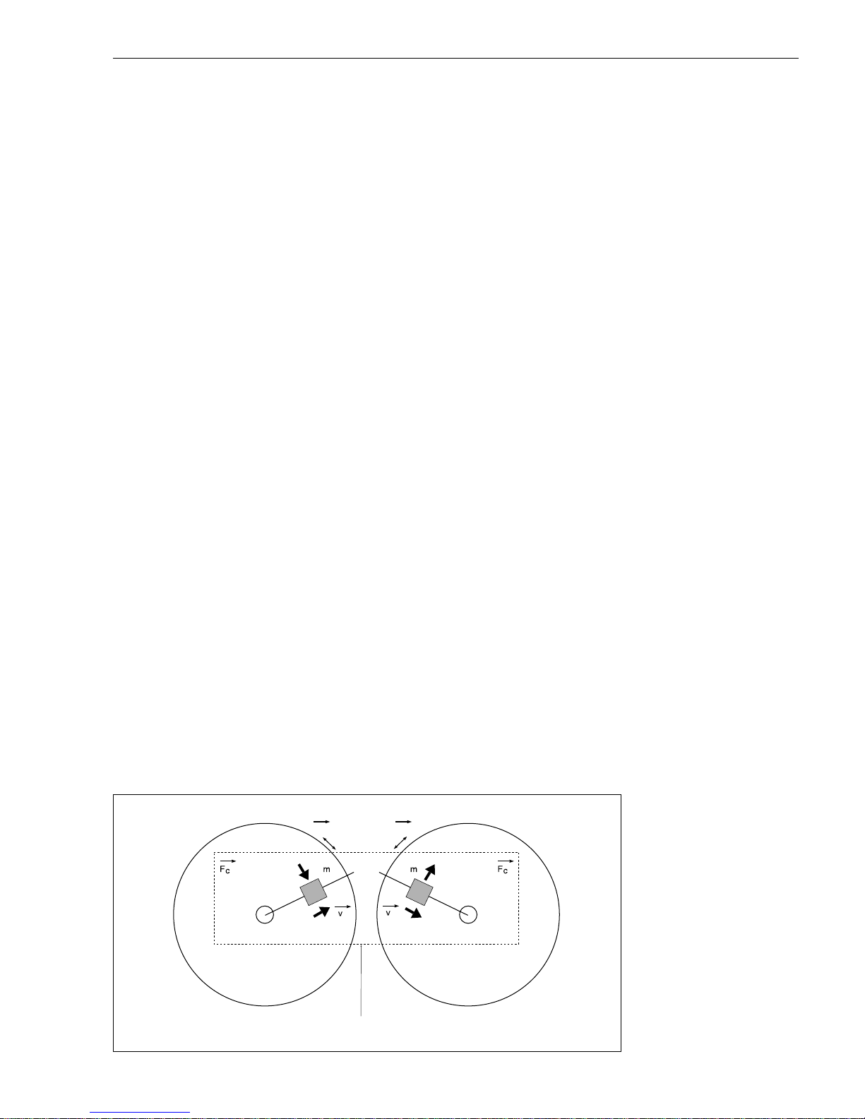
2.22.2 Measuring principle
The measuring principle is based on the controlled generation of Coriolis forces.
These forces are always present when both translational (straight line) and angular
(rotational) movement occur simultaneously.
F
C
= 2 ⋅ ∆m (ω x v)
F
C
= Coriolis force
∆m = mass of moving body
ω = angular velocity
v = radial velocity in a rotating or oscillating system
The amplitude of the Coriolis force depends on the moving mass ∆m, its velocity in
the system v and therefore its mass flow.
→
→
→
→
→
→
→
ωω
∆
∆
Schematic diagram of a measuring tube
ba013y02
Fig. 1:
Coriolis forces in the Promass
measuring tubes
Promass 60 2 Description of the System
Endress+Hauser 7
Page 8
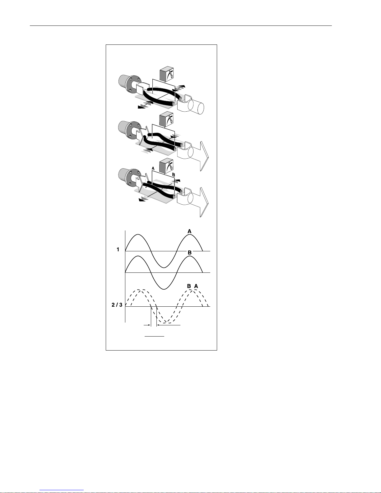
The Promass uses an oscillation instead
of a constant angular velocity ω and two
parallel measuring tubes (Promass M
and F), with fluid flowing through them,
are made to oscillate in antiphase so that
they act like a tuning fork.
The Coriolis forces produced at the
measuring tubes cause a phase shift in
the tube oscillation (see Fig. 2):
• When there is zero flow, i.e. with the
fluid standing still, both tubes oscillate
in phase (1).
• When there is mass flow, the tube
oscillation is decelerated at the inlet
(2) and accelerated at the outlet (3).
As the mass flow rate increases, the
phase difference also increases (A-B).
The oscillations of the measuring tubes
are determined using electrodynamic
sensors at the inlet and outlet.
Unlike Promass M and F, Promass A
and I only has a single measuring tube.
However, the measuring principle and
function of all sensors are identical.
The operating principle is independent
of temperature, pressure, viscosity,
conductivity or flow profile.
Density measurement
The measuring tubes are always made to oscillate at their resonant frequency.
This excitation frequency adjusts automatically as soon as the mass, and therefore
the density, of the oscillating system changes (measuring tubes and fluid).
The resonant frequency is thus a function of the density of the fluid and enables the
microprocessor to produce a density signal.
Temperature measurement
The temperature of the measuring tubes is determined and used to compensate for
temperature effects. The signal produced is a function of the product temperature.
→
ba013y04
ba013y03
1
2
3
Two tub e system
⋅
Fig. 2:
Phase shift of tube vibration with
mass flow.
Balanced Measuring
System
Two-tube system
(Promass M, F)
The system balance is ensured
by the two measuring tubes
vibrating in antiphase.
Single tube system
(Promass A, I)
For single tube systems, other
design solutions are necessary
for system balance than for twotube systems.
Promass A:
For Promass A, an internal
reference mass is used for this
purpose.
Promass I:
For Promass I, the system
balance necessary for flawless
measurement is generated by
exciting an eccentrically located,
counter-oscillating pendulum
mass.
This TMB
TM
(Torsion Mode
Balanced) system is patented
and guarantees accurate measurement, also with changing
process and ambient conditions.
The installation of Promass I is
for this reason just as easy as
with two-tube systems! Special
fastening measures before and
after the meter are therefore not
necessary.
∆
t =
∆ ϕ
2 ⋅ π ⋅ f
≈ m
2 Description of the System Promass 60
8 Endress+Hauser
Page 9
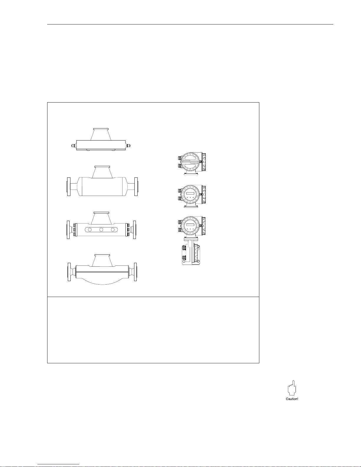
2.3 The Promass 60 measuring system
The Promass 60 measuring system is mechanically and electronically designed for
maximum flexibility with the transmitters and sensors being combined in any variation.
The measuring system consists of:
• Transmitter: Promass 60
• Sensor: Promass A, I, M or F
Caution!
The Promass 60 measuring system is available with various Ex approvals.
Your E+H representative will be pleased to supply information on the approvals
available at present.
All Ex information and specifications are included in a separate documentation which
can be sent by E+H on request.
ba013y05
A
I
M
F
Sensor Transmitter
Promass 60
Without onsite operation
(Blind version)
With onsite operation
With wall mounting
(Remote version)
•
Compact version
•
Remote version (up to 20 meters)
A
DN 1... 4: For very small flow quantities, single tube system in SS or Alloy C-22
I
DN 8... 50: Single straight tube system (titanium), completely welded version
M
DN 8... 80: Two straight measuring tubes (titanium), containment vessel up to 100 bar
DN 8... 25: High pressure version, system pressure up to 350 bar
F
DN 8...100: Two slightly curved measuring tubes in SS or Alloy C-22 (only for DN 8...80),
completely welded version
Technical data: see page 87
Fig. 3:
Promass 60 measuring system
Promass 60 2 Description of the System
Endress+Hauser 9
Page 10

2 Description of the System Promass 60
10 Endress+Hauser
Page 11
3 Mounting and Installation
Warning!
• All instructions given in this section are to be observed at all times in order to
ensure safe and reliable operation of the measuring system.
• Mounting regulations and technical specifications for Ex-certified instruments may
differ from those given below. All mounting regulations and connection values in the
Ex documentation must, therefore, be strictly observed.
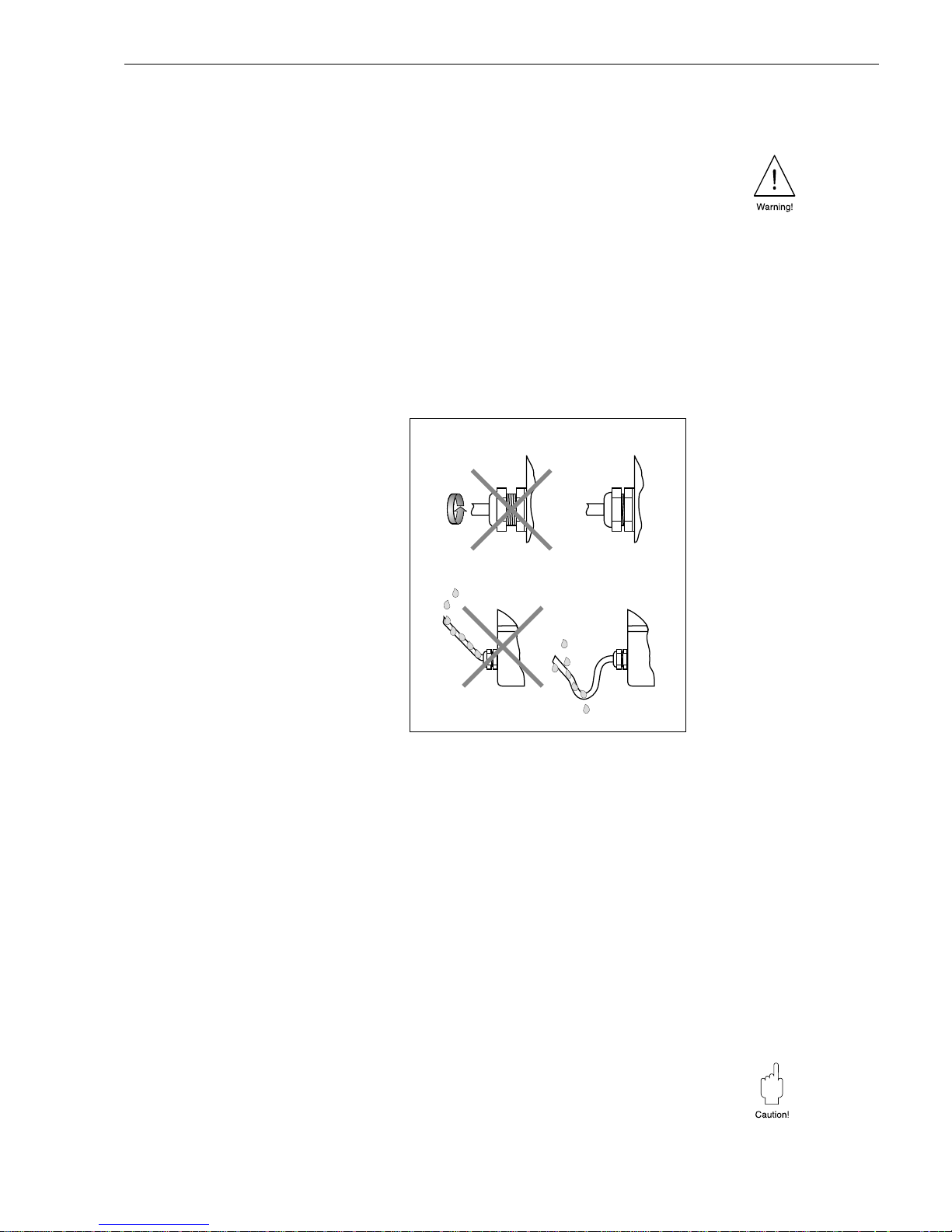
3.1 General information
Protection IP 67 (EN 60529)
The instruments fulfil all the requirements for IP 67. After successful installation in
the field or after servicing, the following points must always be observed in order to
ensure protection to IP 67:
• Housing gaskets must be clean and
undamaged when inserted in the gasket groove. The gaskets may need to
be dried, cleaned or replaced.
• All housing screws and the housing
cover must be firmly tightened.
• The cables used for connecting must
have the correct outer diameter.
• The cable gland must be firmly
tightened (see Fig. 4).
• The cable must loop down before enter-
ing the cable gland to ensure that no
moisture can enter it (see Fig. 4).
• Any cable gland not used must be
replaced with a blind plug.
• The protective bush should not be
removed from the cable gland.
Temperature ranges
• The maximum approved ambient and fluid temperatures must be observed
(see page 91)
• An all-weather cover should be used to protect from direct sunlight when mounting
in the open. This is especially important in warmer climates and with high ambient
temperatures.
Tracing, thermal insulation
With certain fluids heat transfer at the sensor must be avoided. A wide range of
materials can be used to assure the necessary insulation.
Heating can be provided either electrically, e.g. by heating sheets or supplied by
copper pipes with heated water or steam. Heating elements for heat tracing are
available for all sensors.
Caution!
Danger of the electronics overheating! The connector between the sensor/transmitter
housings of the compact version must not be insulated or heated.
The connection housing of the remote version should also be kept free.
Depending on the fluid temperature, certain installation positions are to be observed
(see Fig. 8).
ba013y07
Fig. 4:
Mounting notes for
cable glands
Promass 60 3 Mounting and Installation
Endress+Hauser 11
Page 12
System pressure
It is important to avoid cavitation as this can affect the oscillation of the measuring
tubes.
• No special measures need be taken for fluids which have properties similar to those
of water under normal conditions.
• With volatile liquids (hydrocarbons, solvents, liquified gas), the vapour pressure
must not drop below a point where the liquid then begins to boil.
It is also important not to release gases which are found naturally in many liquids.
This can be prevented by maintaining a high enough system pressure.
Note!
Ideally the sensor should be mounted
• on the discharge side of pumps (avoiding low pressure)
• at the lowest point of a vertical piping
Purge connections
The sensor second containment vessel is filled with dry nitrogen (N
2
). The purge
connection is only to be opened when the vessel is afterward immediately filled with a
dry, inert gas (corrosion protection!).
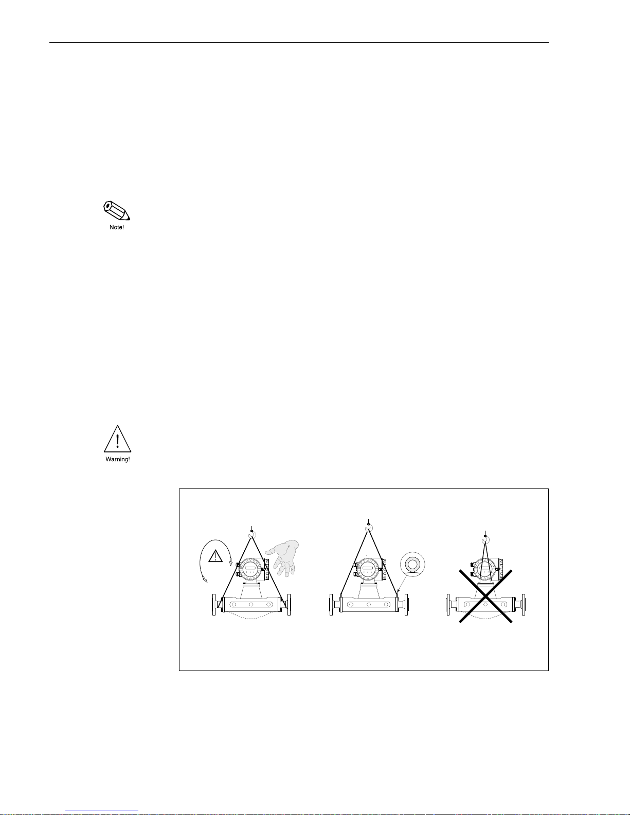
3.2 Transport to the measuring point (DN 40...100)
For transport, measuring instruments with nominal diameters of DN 40...100 may not
be lifted at the transmitter housing or at the connection housing of the remote version.
Use shoulder straps for transport to the measuring points and wrap them around both
process connections (see Fig. 5). Avoid using chains as this might damage the
housing, e.g. scratch the coat of lacquer.
Warning!
Danger of injury by slipping measuring instrument. The centre of gravity of the entire
device is higher than the two suspension points of the shoulder straps. Make sure that
the device does not turn or slip due to the higher centre of gravity during transport.
ba013y46
DN 40...100
DN 80
Promass M
DN 40...100
Correct
Correct
Incorrect
Fig. 5:
Transporting the sensor
DN 40...100
3 Mounting and Installation Promass 60
12 Endress+Hauser
Page 13
3.3 Mounting
• No special fittings such as brackets are required. External forces are absorbed by
the construction of the device, e.g. by the containment vessel.
• For mechanical reasons, and to protect the pipeline, support is recommended for
heavy sensors.
• Due to the high frequency of the measuring tubes, the Promass 60 measuring
system is unaffected by plant vibration.
• When mounting, no special precautions need to be taken for turbulence-generating
devices (valves, bends, T-pieces, etc.) as long as no cavitation occurs.
The following installation instructions are to be carried out for correct operation of the
measuring system:
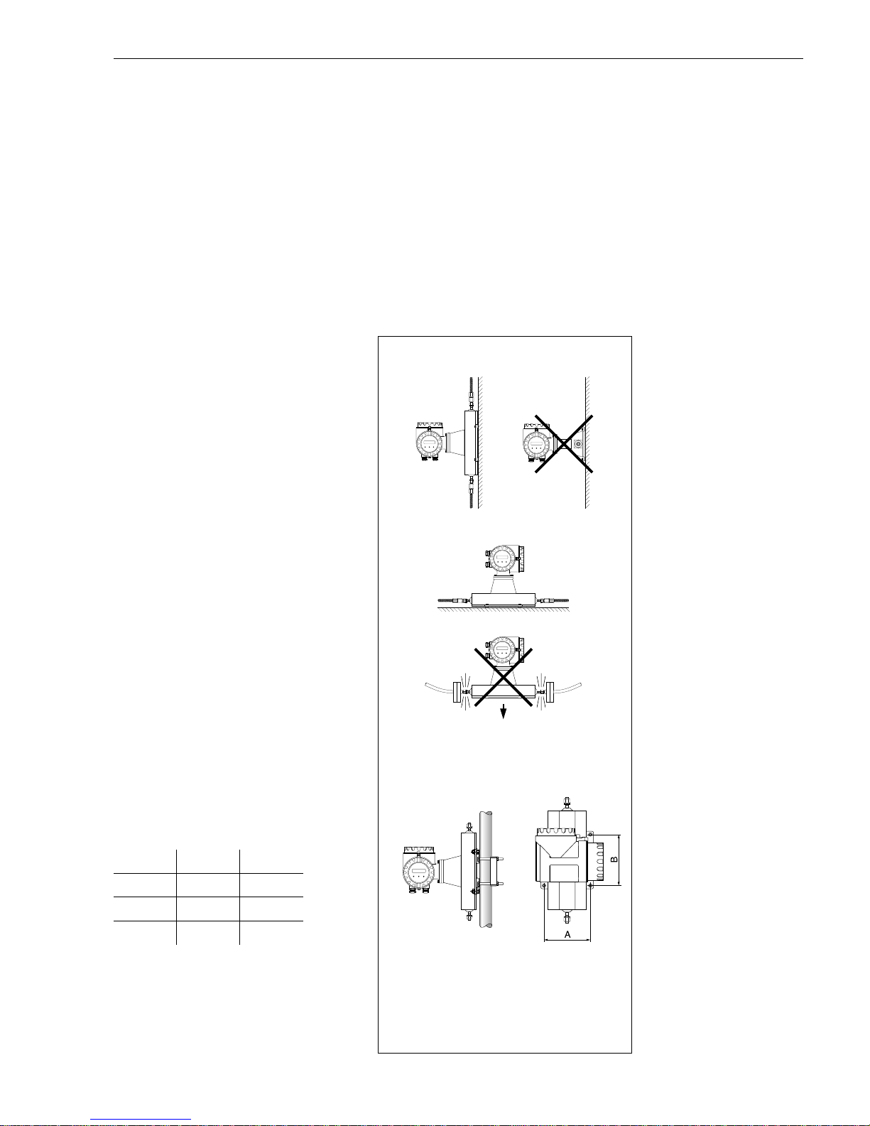
Orientation (Promass A)
Vertical
This is best with the flow direction
upwards. Entrained solids sink downward and gases rise away from the
measuring tube when the product is not
flowing. This also allows the measuring
tube to be completely drained and protects it from solids build-up.
Horizontal
When correctly installed, the transmitter
housing is either above or below the
piping. This assures that no gas bubbles
may collect or solids be deposited in the
curved measuring tube.
Wall and post mounting
The sensor may not be suspended in the
piping, that is, without support or
fixation to avoid excessive stress on the
material around the process connection.
The sensor housing base plate allows
a table, wall, or post mounting. The post
mounting requires a special mounting
set:
DN 1, 2: Order No. 50077972
DN 4: Order No. 50079218
DN A [mm] B [mm]
1 145 160
2 145 160
4 175 220
ba013y63
10...14 kg
Post mountng set for Promass A
(∅
3
/4...3")
Fig. 6:
Orientation Promass A
Promass 60 3 Mounting and Installation
Endress+Hauser 13
Page 14
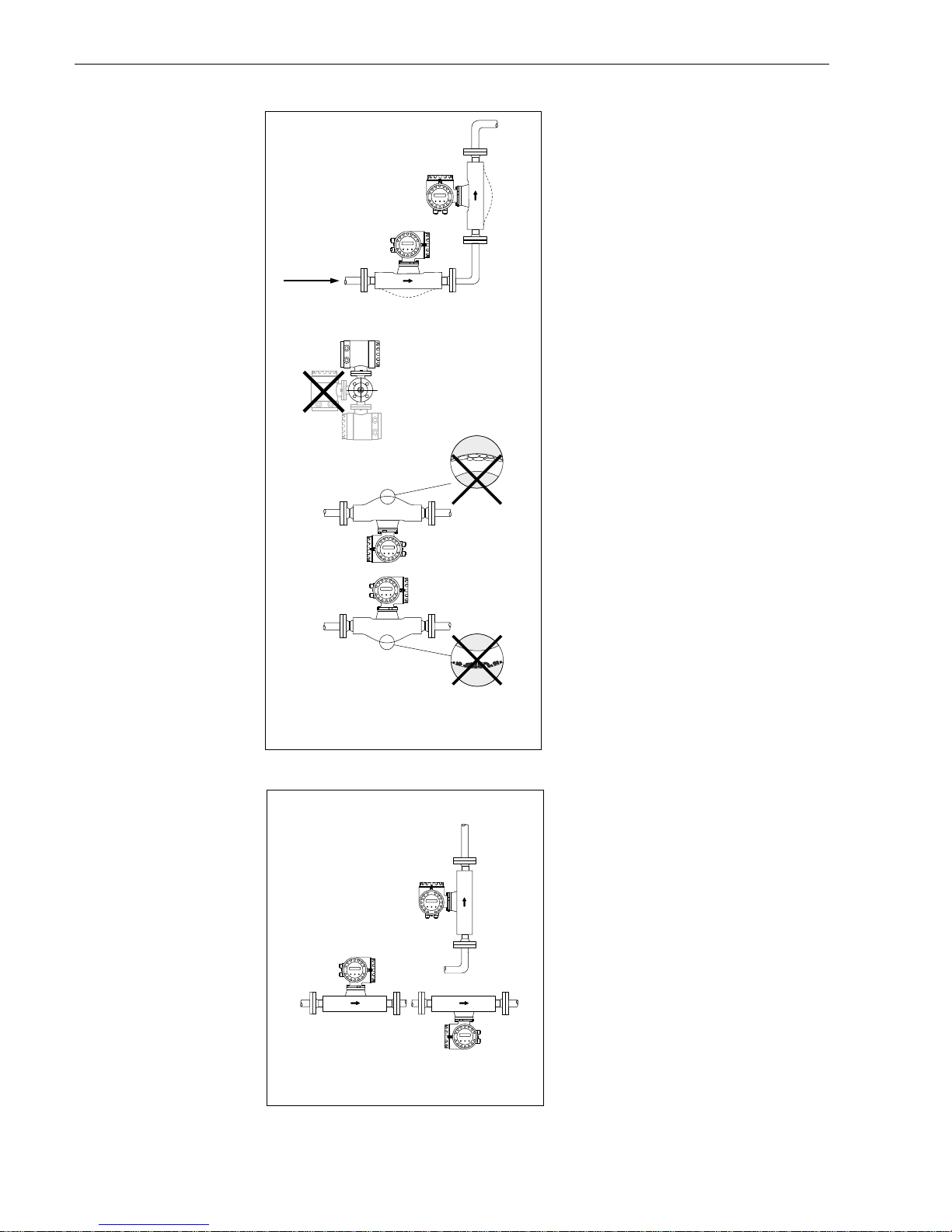
Orientation (Promass I, M, F)
Vertical
This is best with the flow direction
upwards. Entrained solids sink downward and gases rise away from the
measuring tubes when the product is not
flowing. This also allows the measuring
tubes to be completely drained and
protects them from solids build-up.
Horizontal
• Promass I (single tube):
Because of the straight measuring
tube, the sensor can be mounted in
any position of the piping.
• Promass M, F:
The measuring tubes must lie side by
side. When correctly installed, the
transmitter housing is either above or
below the piping (see view A).
• Promass F:
Promass F measuring tubes are
slightly curved. Therefore, the sensor
position is to be adapted to the fluid
properties for horizontal installation:
F1: not suitable for outgassing fluids
F2: not suitable for fluids with solids
content
Fluid temperature/orientation
To ensure that the permitted ambient
temperature range for the transmitter is
not exceeded (-25...+60 °C) positioning
is recommended as follows:
High fluid temperature
• Vertical piping: Position A
• Horizontal piping: Position C
Low fluid temperature
• Vertical piping: Position A
• Horizontal piping: Position B
View A
View A
(Promass M, F)
F1
ba013y08
Positioning
Promass F
Promass I
(can be mounted in any position)
F2
Fig. 7:
Orientation Promass I, M, F
ba013y09
A
B
C
Fig. 8:
Fluid temperature and orientation
3 Mounting and Installation Promass 60
14 Endress+Hauser
Page 15
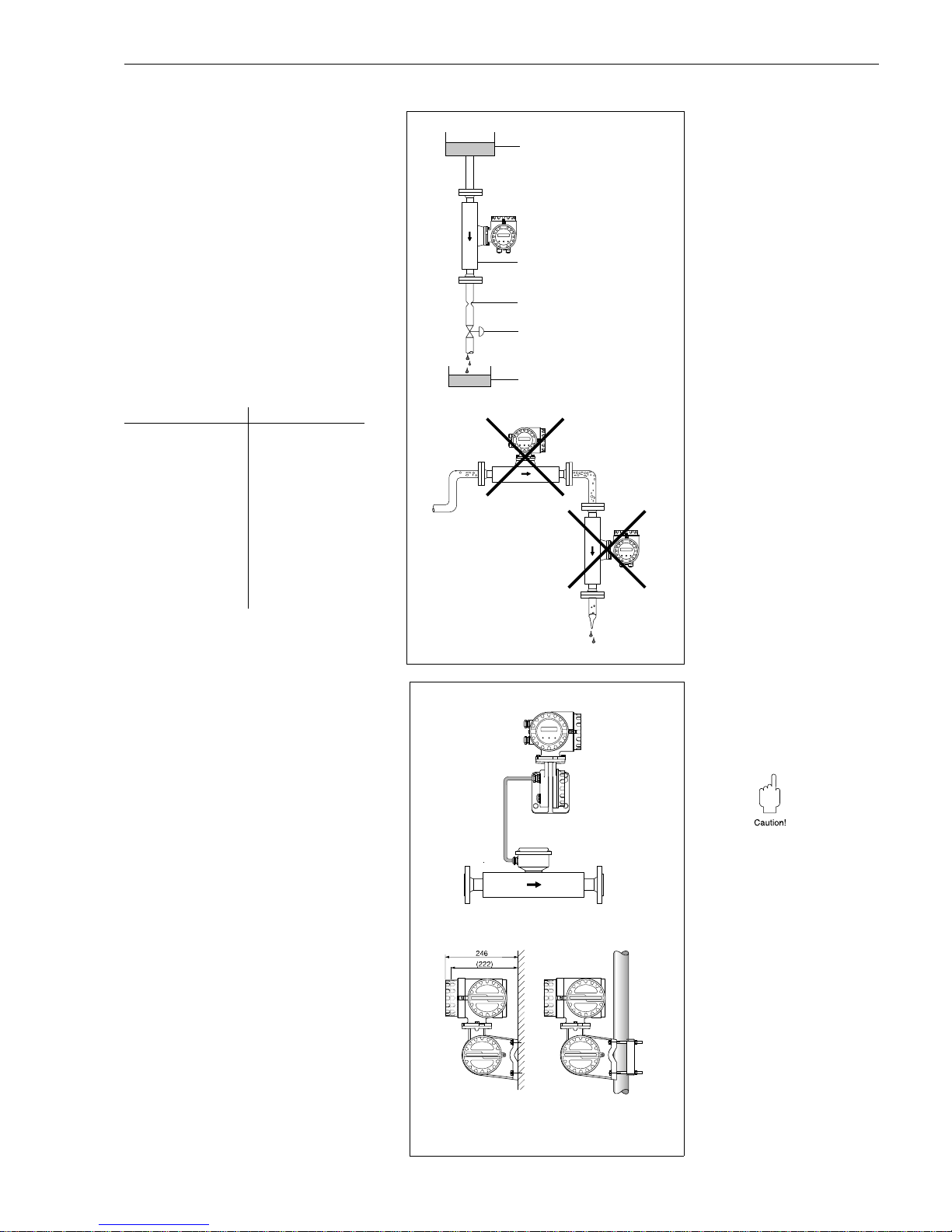
Mounting location
Air or entrained gases in the measuring
tube may cause errors in measurement
and therefore the following mounting
installations are to be avoided:
• Do not install at the highest point of
the piping.
• Do not install in a vertical pipeline
directly upstream of a free pipe outlet.
Correct installation is still possible using
the recommendation in the adjacent
Figure. Restrictions in the piping or an
orifice with a smaller cross section than
the measuring instrument can prevent
the sensor from running empty during
measurement.
Nominal diameter Ø Orifice/restriction
DN 1
DN 2
DN 4
DN 8
DN 15
DN 15 *
DN 25
DN 25 *
DN 40
DN 40 *
DN 50
DN 80
DN 100
0.8 mm
1.5 mm
3.0 mm
6.0 mm
10.0 mm
15.0 mm
14.0 mm
24.0 mm
22.0 mm
35.0 mm
28.0 mm
50.0 mm
65.0 mm
* DN 15, 25, 40 “FB” =
Full bore versions of Promass I
Mounting the transmitter
A wall bracket for the transmitter housing and a 10 or 20 meter, ready-to-use,
sensor connection cable is in the scope
of supply for the remote version.
Caution!
• Please pay attention to page 19
“Connecting the Remote Version”.
• Fix the cable or fix it in a conduit.
• Do not lay cable in the vicinity of
electrical machines or switching
elements.
• In case of the remote version, the
connection housing of the sensor
may not be insulated.
• Ensure potential equalisation between
the transmitter and the sensor
(see page 19).
For post mounting a special mounting
set is available (Order No. 50076905).
Sensor
Orifice
Pipe restriction
Valve
Batching tank
Storage tank
ba013y10
Fig. 9:
Mounting location (vertical piping)
ba013y11
cable length
max. 20 m
Wall mounting Post mounting
(
∅
3
⁄
4
...3")
Fig. 10:
Mounting the transmitter
(Remote version)
Promass 60 3 Mounting and Installation
Endress+Hauser 15
Page 16
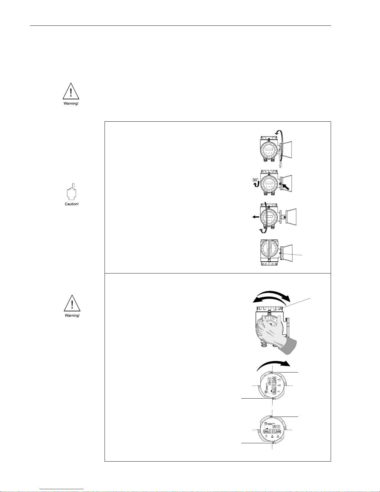
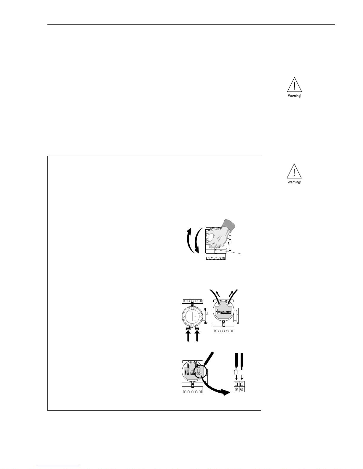
3.4 Rotating the transmitter housing and local display
With the compact version, the transmitter housing and the display field can be rotated
in 90° steps so that the instrument can be mounted in almost any position in the
piping to ensure easy handling and read-off.
Warning!
The following description does not apply to Ex-certified measuring instruments.
Please observe the respective, separate Ex documentation in every detail.
➋
➊
➐
➍
➌
➌
➎
➎
ba013y13
➏
➊
➋
➌
➍
➎
ba013y12
Rotating the transmitter housing
➊
Loosen the mounting screws
(approx. two turns).
➋
Rotate the transmitter housing as far as
the groove of the nut.
➌
Carefully pull out the transmitter housing.
Caution!
Do not damage the connection cable
between the transmitter and sensor!
➍
Rotate the transmitter housing to the
position required.
➎
Push back into the latch again and tighten
the two screws securely.
Rotating the local disp la y
Warning !
Danger from electric shock.
Switch off power supply before opening the housing.
➊
Loosen the safety grip (3 mm Allen key).
➋
Unscrew the cover from the electronics area.
➌
Undo both Phillips screws.
➍
Rotate the display.
➎
Tighten the Phillips screws again.
➏
Replace the cover of the electronics area on
the transmitter housing.
➐
Tighten the Allen screws of the
safety grip securely.
Fig. 11:
Rotating the transmitter housing
and the local display
3 Mounting and Installation Promass 60
16 Endress+Hauser
Page 17
4 Electrical Connection
4.1 General information
Warning!
• The information in Section 3.1 must be observed in order to maintain protection
to IP 67.
• When connecting Ex-certified flowmeters, all appropriate instructions and connec-
tion diagrams in the separate Ex documentation to this Operating Manual must be
observed.
• When using the remote version, only sensors and transmitters with the same serial
number are to connected together. Communication errors if this is not the case.
4.2 Connecting the transmitter
➊ ➏
Signal
cable
Power supply
cable
➎
➋
➍
➌
ba013y14
➊
Loosen the screws of the safety grip
(3 mm Allen key).
➋
Unscrew the cover of the terminal
compartment.
➌
Push the power and signal cables
through the appropriate cable glands.
➍
Wire up according to the connection
diagrams (see diagram in the screw
cover or Fig. 13):
The power supply is connected to
Terminal 1 (L1 or L+), Terminal 2 (N or L–)
and the ground terminal.
– Stranded-wire cabling: cover with an
end sleeve max. 4 mm
2
– Single wire cabling: max. 6 mm
2
➎
Screw the cover of the terminal
compartment securely back onto the
transmitter housing.
➏
Tighten the Allen screws of the safety grip
securely.
Warning !
•
Danger from electric shock! Switch off the power supply before unscrewing the cover!
•
Connect the ground wire to the ground terminal on the housing before turning on the power supply.
•
Check that the local power supply and frequency agree with the information on the
nameplate. All relevant national regulations for mounting must also be observed.
Fig. 12:
Connecting the Promass 60
transmitter
Promass 60 4 Electrical Connection
Endress+Hauser 17
Page 18
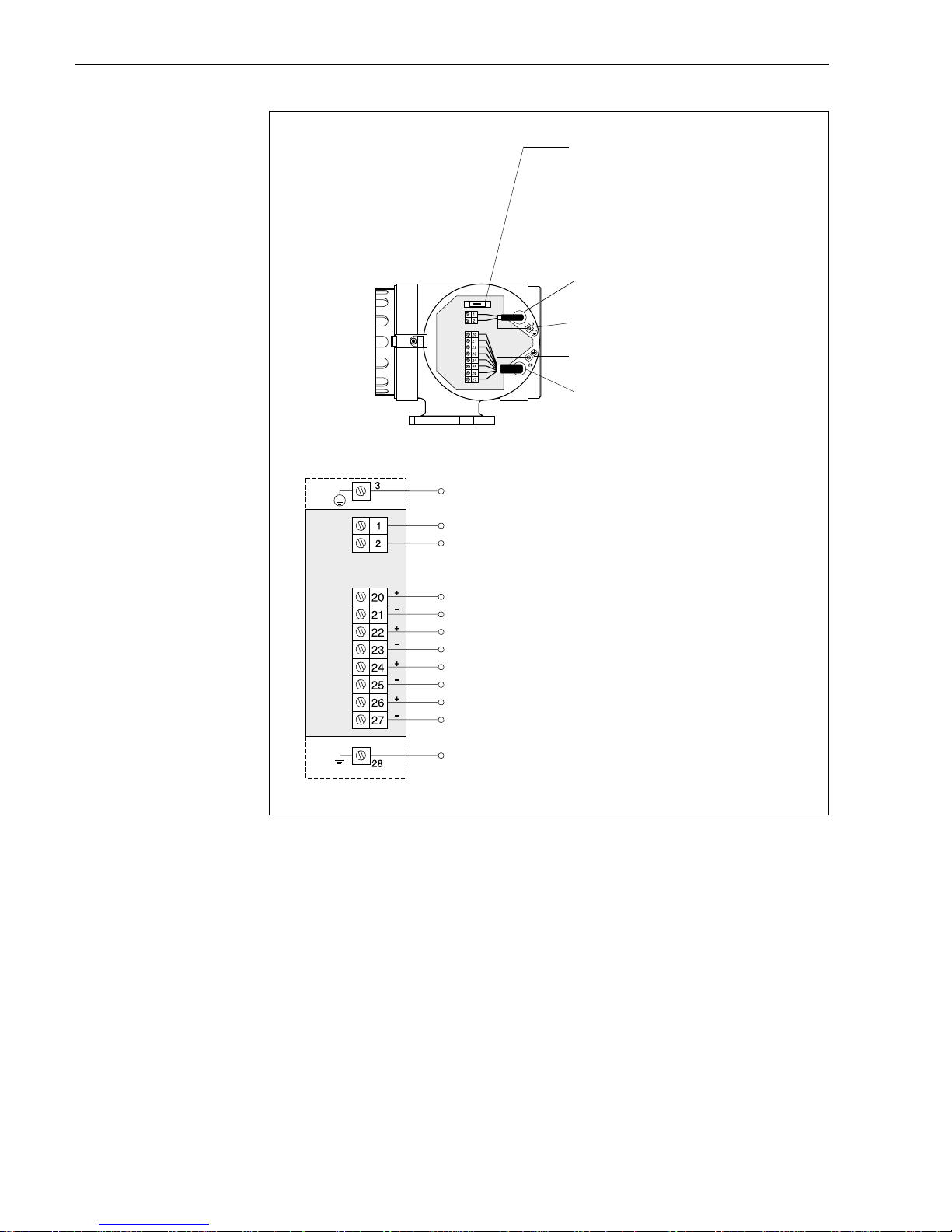
L1
}
for AC
L +
} for DC power supply
NL–
0...400 Hz (f
max
= 500 Hz)
max. 30 V / 250 mA
max. 30 V / 250 mA
→
System error indication
→
Flow directi on
3...30 V DC, Ri = 1.8 k
Ω
→
Positive zero return, Z ero point ca libration
→
Totalizer reset
0/4...20 mA, RL < 700
Ω
HART protocol: 4...20 mA, R
L
≥
250
Ω
Pulse output (passive)
Status output (passive)
Auxiliary input
Current output (active)
Ground connection (screening of signal cable)
Fuse:
•
Power supply 20...55 V AC / 16...62 V DC:
2.5 A slow-acting / 250 V; 5.2 x 20 mm
•
Power supply 85...230 + 10% V AC:
1 A slow-acting / 250 V; 5.2 x 20 mm
Power supply cable
Ground terminal for ground wire
Ground terminal for cable screening
Signal cable
Ground connection (ground wire)
ba013y15
Fig. 13:
Electrical connection:
power supply, input and outputs
4 Electrical Connection Promass 60
18 Endress+Hauser
Page 19

4.3 Connecting the remote version
The remote version is supplied with a 10 or 20 meter ready-to-use cable which is
already connected to the sensor.
Sensor
connection housing
Transmitter
connection housing
ba013e58
Cable specifications:
brn = brown; wht = white; pnk = pink; yel = yellow; grn = green; gry = grey
6 x 0.38 mm
2
PVC cable with
common
screening and individually screened cores.
Conductor resistance: ≤ 50 Ω/km; Capacitance: core/screen ≤ 420 pF/m
Permanent operating temperature: –25...+90 °C
With the remote-mounted version the cables between sensor and transmitter must always
be screened and grounded at both ends. This is done at the ground terminals
inside the connection housing of sensor and transmitter.
➊
Transmitter
connection housing
➋ ➎
➌
Sensor
cable length
max. 20 m
Warning!
Danger from electrical shock! Switch off the power supply before unscrewing the cover
of the electronics area from the transmitter housing and the cover from the connection housing.
➊
Connection in the terminal area is carried out as described for the compact
version (see page 17, 18)
➋
Loosen the safety grip (3 mm Allen key). Unscrew the cover of the transmitter
connection area.
➌
Push the connection cable through the appropriate cable gland.
➍
Connect the cable according to the electrical connection diagram
(see Figure below or diagram in the screw cover).
➎
Screw on the connection housing cover again securely. Tighten the Allen screws
of the safety grip securely.
ba013y57
➍
Fig. 14:
Connecting the remote version
Promass 60 4 Electrical Connection
Endress+Hauser 19
Page 20
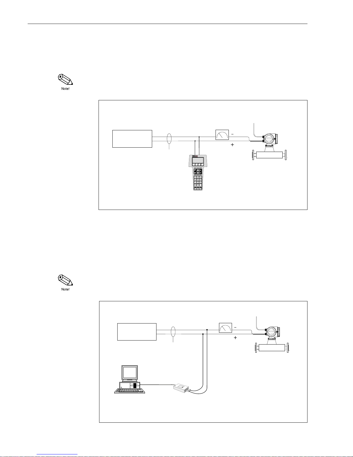
4.4 Connecting HART Handheld DXR 275
The following connection versions are available to the user:
• Direct connection to the Promass transmitter via Terminals 26 / 27
• Connection via the analogue 4...20 mA cable of the current output
Note!
In both cases the measuring loop must have a minimum resistance of 250 Ω.
4.5 Connecting Commubox FXA 191 (Commuwin II)
The following connection versions are available to the user:
• Direct connection to the Promass transmitter via Terminals 26/27
• Connection via the analogue 4...20 mA cable of the current output
Note!
• In both cases the measuring loop must have a minimum resistance of 250 Ω .
• Move the switch on the Commubox to ‘HART’!
Sreening
HART handheld terminal
DXR 275
Power supply
ba013y84
≥
250
Ω
27
26
Other instruments or
PLC with passive input
Fig. 15:
Electrical connection
HART-handheld DXR 275
other instruments or
PLC with passive input
Screening
Power supply
Personal Computer
with E+H software
“Commuwin II” and
HART DDE server
Commubox
FXA 191
ba013y83
≥
250
Ω
RS 232C
27
26
Fig. 16:
Electrical connection
Commubox FXA 191
4 Electrical Connection Promass 60
20 Endress+Hauser
Page 21
5 Operation
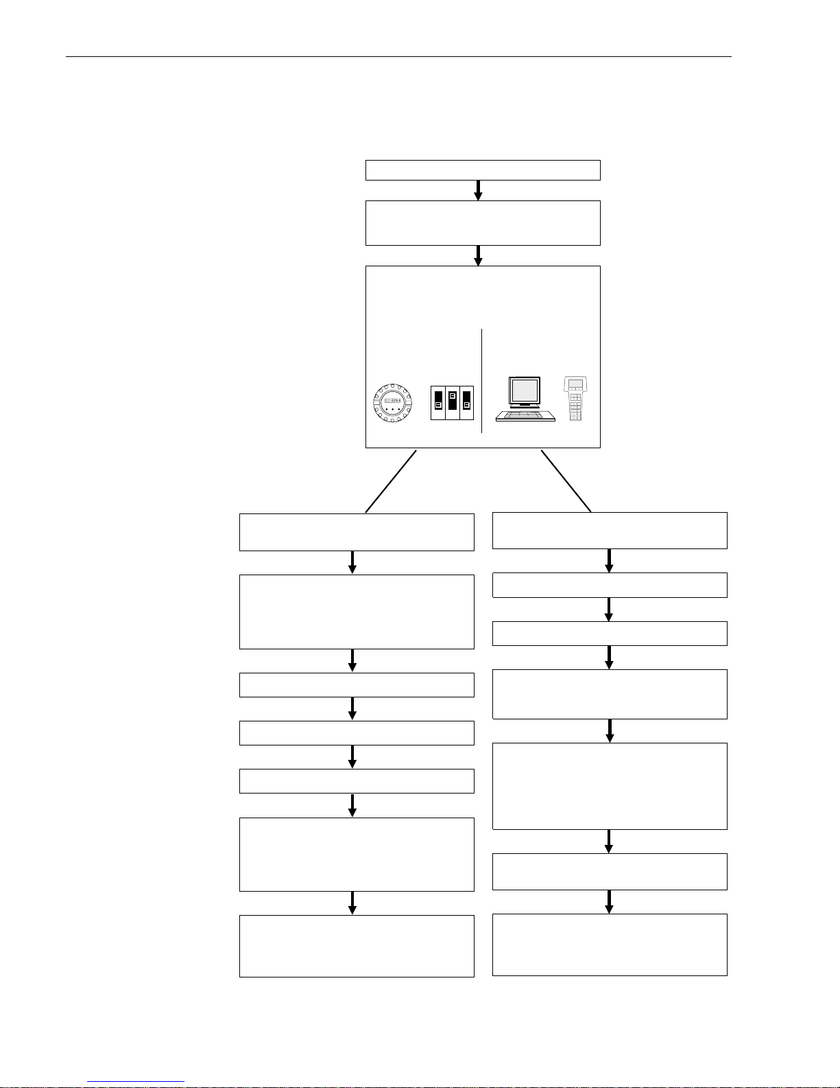
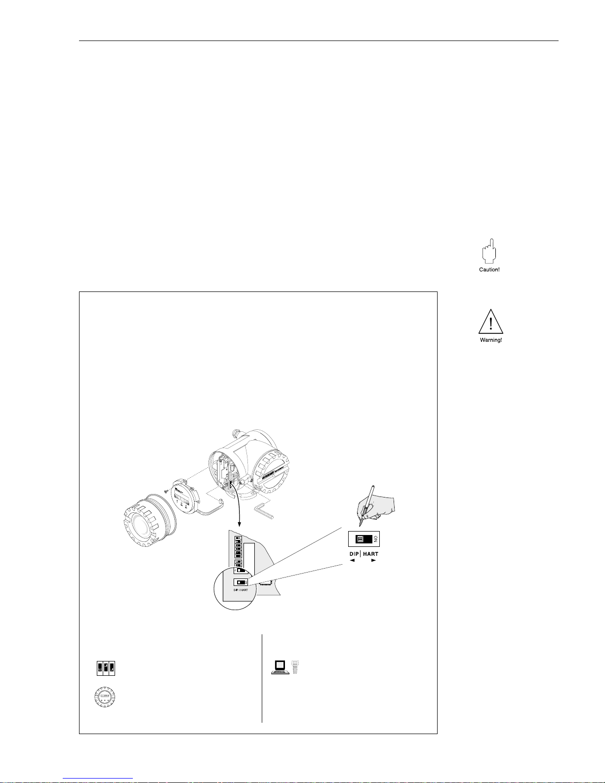
5.1 Selection of operating mode (DIP switches/display, HART)
Promass 60 can basically be operated in two different ways:
• Configuration with DIP switches and/or the local display
• Configuration with HART protocol (e.g. via Commuwin II, HART handheld, etc.)
The two operating modes can not be used simultaneously. By using the “DIP/HART”
switch on the communication pcb (see Fig. 17), the operating mode is fixed and
thereby also the instrument’s functionality. An overview of all instrument functions,
depending on the operating mode, can be found in Chapter 10.
Caution!
With the switch in the “HART” position, switches Nr. 1–12 are deactivated. Switching
back to the “DIP” switch operating mode overwrites settings or data entries previously
made in the HART or Commuwin matrix.
ba013y87
➀
➁
➂
➃
Warning!
•
Danger from electrical shock! Switch off the power supply before unscrewing the cover
of the electronics area from the transmitter housing.
•
Do not fail to observe the supplementary Ex documentation for Ex-certified instruments,
especially the waiting time before opening the housing.
1. Loosen the screws of the safety grip (3 mm Allen key).
2. Unscrew the cover of the electronics area.
3. Remove the local display if present.
4. Set “DIP/HART” to the desired position (also DIP switch Nrs. 1–12 if applicable, see page 22)
5. Reassemble in reverse sequence.
Fig. 17:
Selection of operating mode
(function overview: see page 97)
“DIP”
→Configuration with
DIP switches & display
DIP switches:
Basic instrument functions → page 22
Local display:
Additional functions → page 24
“HART” (ON)
→ Configuration with
HART protocol
HART handheld → page 25
Commuwin II → page 27
Promass 60 5 Operation
Endress+Hauser 21
Page 22

5.2 Configuration with DIP switches
Factory settings
DIP switches No. 1–12
ON Creep suppression activated
OFF Creep suppression deactivated
ON Status output: flow direction
OFF Status output: indication of system errors
ON US engineering units [lb, gal]
OFF SI engineering units [kg, t; l, m
3
]
ON 0...20 mA current range
OFF 4...20 mA current range
Setting pulse value:
For switch settings → see
Tables
on page 37
Scaling the full scale value (= flow at 20 mA)
For switch settings → see
Ta bles
on page 38
(Current output)
ON Short-cycle batching on **)
OFF Short-cycle batching off
ON Auxiliary input: Positive zero return *)
OFF Auxiliary input: Zero point calibration *)
client settings
✍
ba013y25
Warning!
•
Danger from electrical shock! Switch off the power supply before unscrewing the
cover of the electronics area from the transmitter housing.
•
Do not fail to observe the supplementary Ex documentation for Ex-certified
instruments, especially the waiting time before opening the housing.
1. Loosen the screws of the safety grip (3 mm Allen key).
2. Unscrew the cover of the electronics area.
3. Remove the local display if present (see page 16).
4. Set the DIP switches (description of functions → see page 31 ff.) .
5. Reassemble in reverse sequence.
➀
➁
➂
➃
Fig. 18:
Setting instrument functions
with DIP switches
Note!
On request, Promass 60
measuring instruments are also
available with customised
parameterisation.
*) or totalizer reset via local
display (see page 35)
**) For filling cycle up to <60 sec.
5 Operation Promass 60
22 Endress+Hauser
Page 23
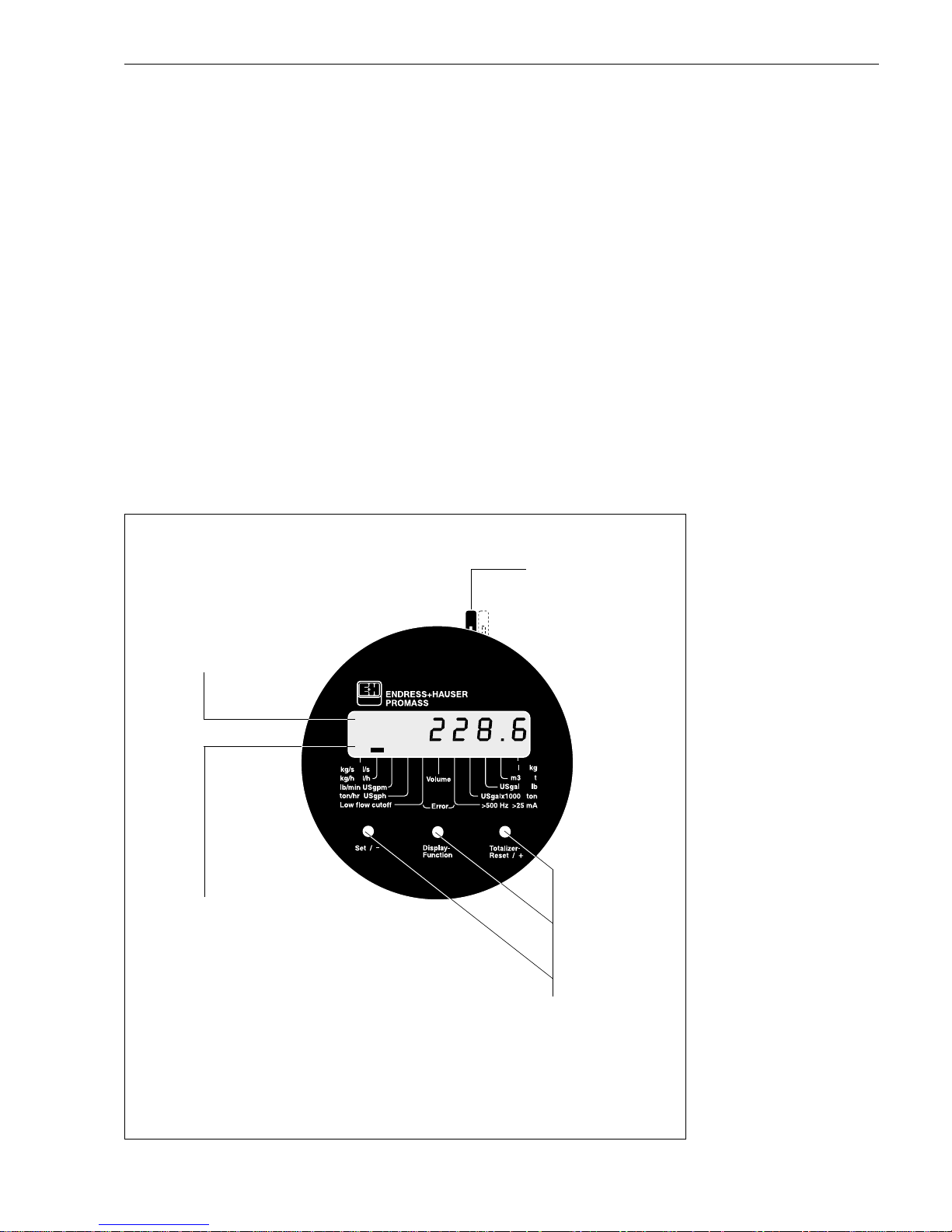
5.3 Configuration with the local display
Using the Promass 60 local display, important variables can be read off and controlled directly at the measuring point. Three operating keys are used to select and
activate the various functions.
• Actual flow rate (display function)
• Actual totalizer value (display function)
• Number of totalizer overflows (display function)
• Alternating display flow/totalizer
• Static zero point calibration
• Enter zero point
• Density-value display/start density calibration
• Mass or volume measurement
• Pressure pulse suppression (batching)
• Test function for checking the display elements
The function of the auxiliary input may additionally be changed with the help of a
jumper positioned on the local display (see page 35).
All measurement data (e.g. totalizer value) and configuration values are safely stored
on power supply failure. With system errors the outputs respond as described on
page 59.
ba013y64
Operating keys
With these three keys, functions may be
accessed, activated, and/or numbers
entered (see next page).
11 Display segmen ts
The segments displayed allow an immediate
reading of the engineering unit, process,
and instrument status.
Example:
If the creep falls below of a certain value
(see Table on page 31), the display segment
above “Low-flow cutoff” becomes immediately
visible.
LCD
Display of all measured
values, operating, and
status reports
Jumper
Configuration of
the auxiliary input
Fig. 19:
Local display Promass 60
Promass 60 5 Operation
Endress+Hauser 23
Page 24
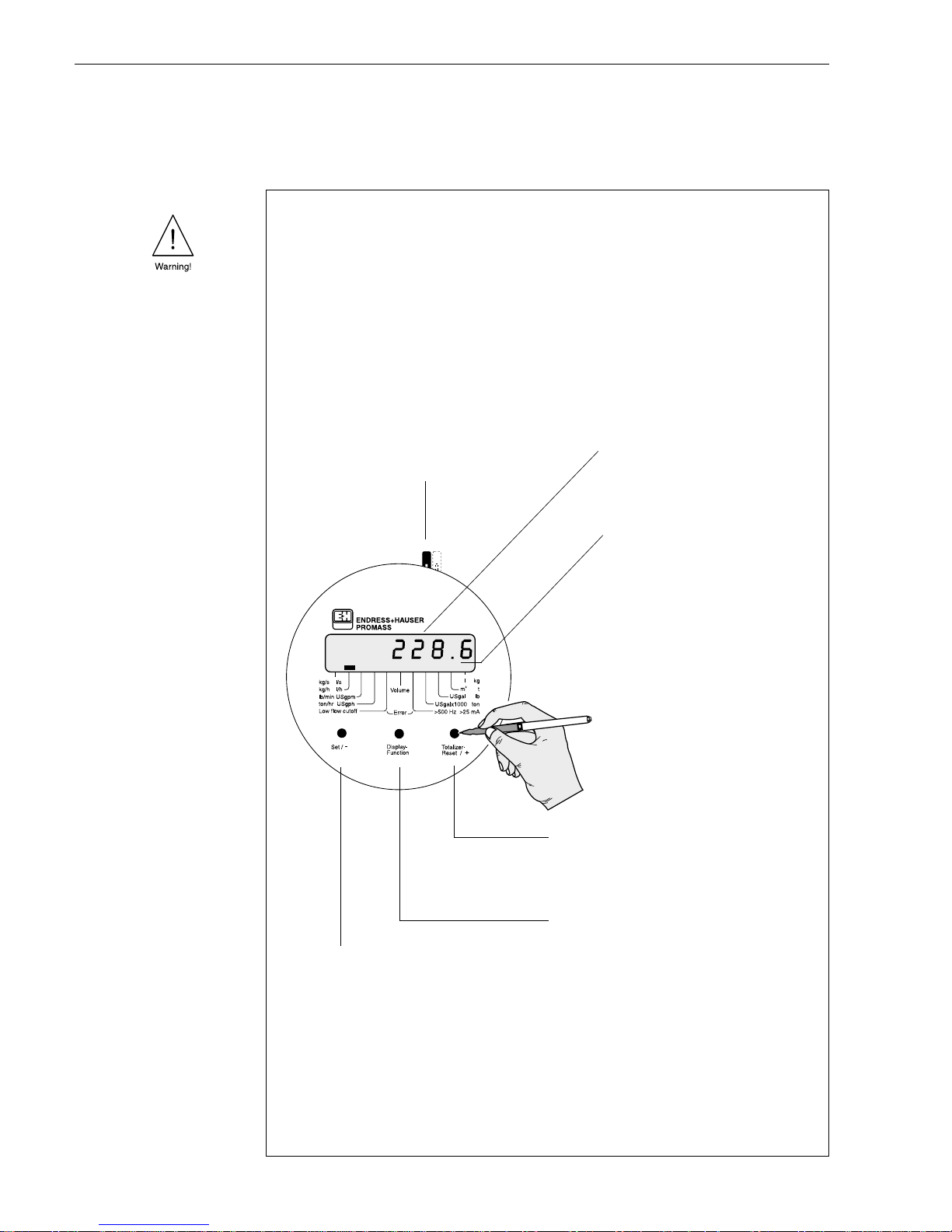
Operation of the local display
It is possible to access, activate, and set various functions in sequence with the help
of the three operating keys on the local display.
ba013y28
Jumper
Configuration of auxiliary input
→
see page 35
Set / –
✍
This key is used for carrying out the following
operations within the appropriate function:
•
Selecting the engineering units
•
Entering of numerical values (–)
•
Zero point or density calibration.
Totali zer reset / +
✍
•
This key is used for resetting the
totalizer to ’0’ (in the “
tot
” function only).
•
Entering of numerical values (+)
Display function
✍
This key is used for selecting the function
resp. the display mode required:
–
rAtE
Flow rate display
–
tot
Totalizer display
–
dISP-OF
Display totalizer overflow
–
rAtE-tot
Display flow rate and totalizer
–
O.-AdJuSt
Zero point adjustment
–
PIPO
Zero point value
–
dEnSItY
Density adjustment
–
MAS-VOL
Operating mode (mass/volume)
–
PrES-SUP
Pressure pulse suppression
–
tESt
Display test function
Function description → see page 39
LCD, 8-character
All measured values, operating and
status indications are shown here.
11 display seg ments
The appropriate segments serve to
provide clear identification of
engineering units, instrument and
process status:
•
Creep too low (Low flow cutoff)
•
Velocity of fluids is too high:
full scale value exceeded,
>500 Hz >25 mA
•
System fault (Error)
•
Present engineering units
•
Volume measuring activated/
de-activated
Warning!
Danger from electrical shock! With the housing cover removed, protection against accidental
contact is no longer present.
Components with high voltages are exposed below the local display (danger from electric shock).
Avoid any contact with the electronic components which lie below the local display, and do not use
any electrically conductive object to depress the programming keys.
1. Loosen Allen screw (3 mm) of the safety grip. Unscrew the cover of the electronics
compartment.
2. The keys may now be operated by pressing with a thin (non-conductive) pin.
A switching cycle takes about 0.5...0.8 seconds.
3. Firmly screw back the cover of the electronics compartment to the transmitter housing
once the settings have been entered. Firmly tighten the Allen screw of the safety grip.
Fig. 20:
Operation of the local display
5 Operation Promass 60
24 Endress+Hauser
Page 25
5.4 Configuration with the HART protocol
For configuration with HART protocol, there are basically two possibilities:
• Configuration with the “HART handheld DXR 275”.
• Configuration with a PC using special software, e.g. “Commuwin II” and the
“Commubox FXA 191” HART modem.
All functions available with HART protocol are fully described in Chapter 6.3.
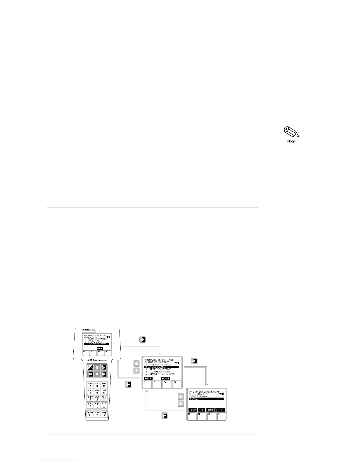
Configuration using the “HART handheld DXR 275”
Selection of Promass 60 instrument functions when using the HART handheld
is via various menu levels or using the HART operating matrix respectively
(see Fig. 22).
Notes!
• The HART protocol requires a 4...20 mA setting for the current output.
The 0...20 mA setting is only selectable with the DIP switches.
• All functions are accessible at all times with the HART handheld terminal i.e.
programming is not locked.
The HART operating matrix can, however, be locked by entering any value except
“0 or 60” in the function “ACCESS CODE”. Data can then no longer be changed.
The operating matrix can again be enabled by entering the code number “0 or 60”.
• Further information on the HART handheld is given in the appropriate operating
manual in the carrying case.
Procedure
1. Switch on handheld terminal:
a. The transmitter is not yet connected → The HART main menu is displayed → Continue with
“Online”
b. The transmitter is already connected → The menue level “Online” is immediately shown.
2. “Online” menu level:
→
Actual measurement data including flow, totalizer sum, etc. are continually shown.
→
Via “MATRIX GROUP” you have access to the HART operating matrix (see page 26),
then to the function group (e.g. CURRENT OUTPUT) and finally to the desired function,
e.g. “FULL SCALE”.
3. Enter values or change the setting.
4. The field “SEND” is shown by pressing the “F2” function key. By pressing the “F2” key,
all values and settings entered with the handheld terminal are registered by the Promass
measuring system. Confirm with the “F4” key.
5. Press “F3” HOME function key to return to the “Online” menu level. The actual values measured
by the Promass flowmeter with the new settings can now be read off.
ba013y81
Fig. 21:
Operating the HART handheld
(example)
Promass 60 5 Operation
Endress+Hauser 25
Page 26
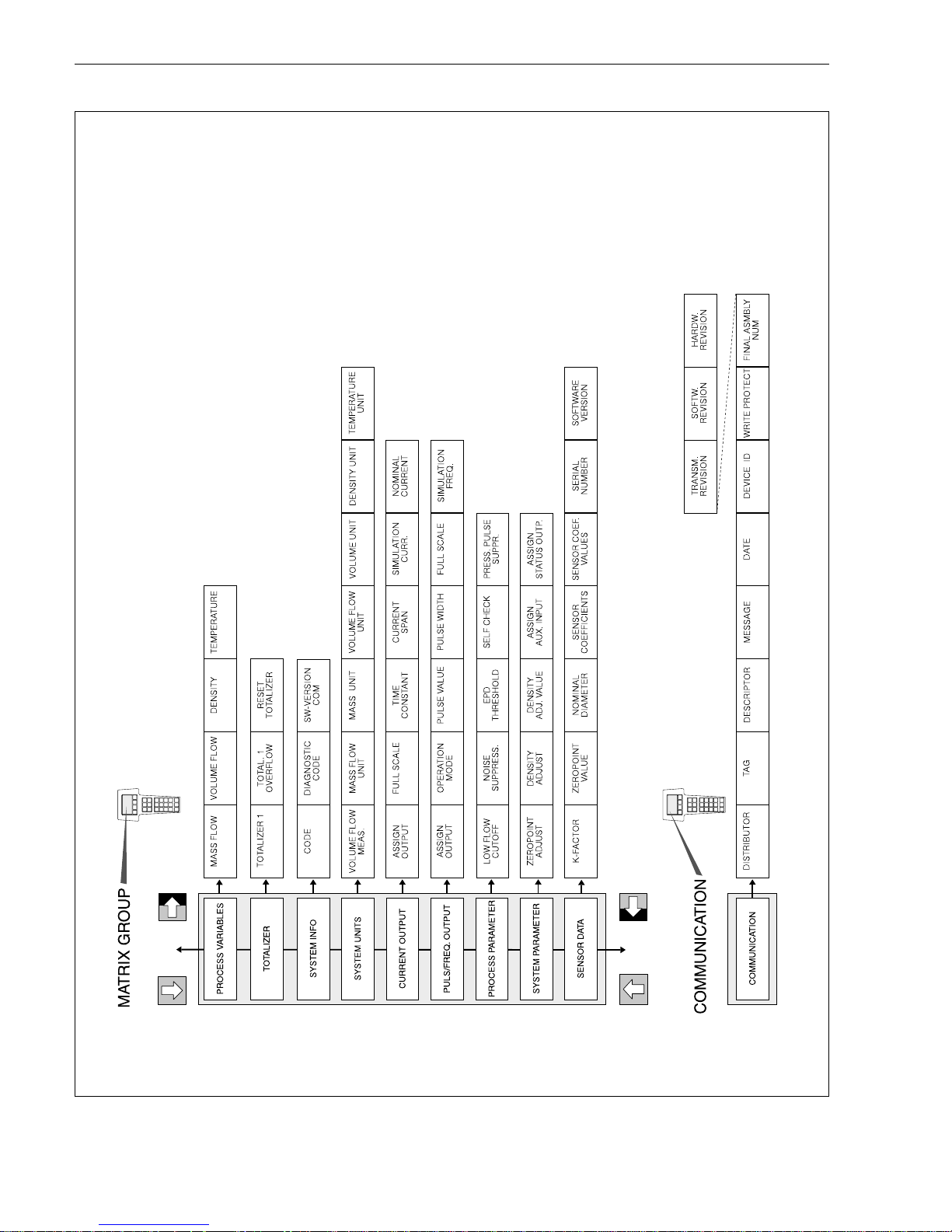
ba013e82
Fig. 22:
HART operating matrix Promass 60
(Function description: see page 43)
5 Operation Promass 60
26 Endress+Hauser
Page 27

Configuration using “Commuwin II” software
Commuwin II is a universal program for remote operation of field and control-room
devices.
With the Commubox FXA 191, the Promass 60 can be connected to the RS 232 serial
interface of a personal computer. This makes remote configuration possible using the
E+H Commuwin II program.
Commuwin II offers the following functions:
• parameterization of functions (see operating matrix, page 28),
• visualization of measuring values,
• saving of instrument parameters,
• device diagnostics (see page 63 ff.),
• measuring-point documentation.
Commuwin II may also be combined with other software packages to visualize
processes.
Note!
For additional information on Commuwin II, see the following E+H documentation:
• System Information: SI 018F/00/en “Commuwin II”
• Operating Manual: BA 124F/00/en “Commuwin II Operating Program”
5.5 Commissioning
Before switching on the measuring system, the following checks should be carried
out again:
•
Installation (see page 11)
Does the directional arrow on the nameplate agree with the actual flow direction in
the piping?
•
Electrical connection (see page 17)
Check electrical connections and terminal coding. Check that the local power
supply and frequency agree with the information stated on the nameplate.
•
Configuration mode (see page 21)
Is the “DIP / HART” DIP switch in the desired position?
If these checks are successful, then switch on the power supply.
The instrument is now ready for use.
Promass 60 5 Operation
Endress+Hauser 27
Page 28

“Commuwin II” operating matrix
H0 H1 H2 H3
V0 PROCESS VARIABLE
MASS FLOW VOLUME FLOW DENSITY TEMPERATURE
V1 TOT ALIZERS
TOT ALIZER 1 TOTAL. 1
OVERFLOW
RESET TOTALIZER
0: CANCEL
1: TOTALIZER 1
V2 SYSTEM INFO
ACCESS CODE DIAGNOSTIC CODE MULTI DROP ADDRESS SOFTWARE VER. COM
V3 SYSTEM UNITS
VOLUME FLOW MEAS
0: OFF
1: VOLUME FLOW
MASS FLOW UNIT
3: kg/s
5: kg/h
10: lb/min
13: ton/hr
MASS UNIT
1: kg
2: t
3: lb
4: ton
FLOW RATE UNIT
5: l/s
7: l/h
18: Ugpm
19: Ugph
V4 CURRENT OUTPUT
ASSIGN OUTPUT
0: MASS FLOW
1: VOLUME FLOW
FULL SCALE 1 TIME CONSTANT CURRENT RANGE
1: 4–20 mA
3: 4–20 mA NAMUR
V5 PULS / FREQ. OUTPUT
ASSIGN PULS / FREQ
0: MASS FLOW
1: VOLUME FLOW
OPERATION MODE
0: PULSE
1: FREQUENCY
PULSE VALUE PULSE WIDTH
V6 PROCESSING
PARA.
LOW FLOW CUTOFF NOISE SUPPRESSION EPD THRESHOLD SELF CHECK
1: CYCLIC
2: SMARTPLUS
V7 SYSTEM PARAMETER
ZERO ADJUST
0: CANCEL
1: START
CALIBR. MODE
0: FLUID 1
2: DENSITY ADJUST
4. CANCEL
DENS. ADJ. V ALUE ASSIGN AUX. INPUT
0: RESET TOTAL. 1
1: ZEROPOINT ADJUST
2: POS. ZERO RETURN
V8 SENSOR DATA
K-FACTOR ZEROPOINT NOMINAL DIAMETER SENSOR DATA
V9 SERVICE & ANALYSIS
VA SETUP
TAG NUMBER
5 Operation Promass 60
28 Endress+Hauser
Page 29

“Commuwin II” opera tin g ma trix
H4 H5 H6 H7...H9
VOLUME UNIT
2: l
4: m3
6: USgal
8: USgal*1000
DENSITY UNIT
1: kg/dm3
7: g/cc
TEMPERA TURE UNIT
0: C (Celsius)
1: K (Kelvin)
2: F (Fahrenheit)
3: R (Rankine)
SIMULATION CURR.
0: OFF
2: 2 mA
3: 4 mA
5: 12 mA
7: 22 mA
8: 25 mA
ACTUAL CURRENT
FULL SCALE FLOW SIMULATION FREQ.
0: OFF
1: 0 Hz
2: 2 Hz
3: 10 Hz
4: 1 kHz
PRESS. PULSE SUPPR
O. OPEN COLLECTOR
(Assign Status Output)
0: ERROR
1: FLOW DIRECTION
RESET DEVICE
0: CANCEL
7: REBOOT SYSTEM
SENSOR DATA VALUE SERIAL NUMBER SOFTWARE VERSION
Promass 60 5 Operation
Endress+Hauser 29
Page 30

5 Operation Promass 60
30 Endress+Hauser
Page 31

6 Function Description
6.1 DIP switch functions
Cut-in and cut-off points
DN On Off On Off On Off
[mm] in [kg/h] resp. [l/h] ** in [lb/min] in [USgal/min] **
1
2
4
8
15
15*/25
25*/40
40*/50
80
100
0.05655
0.22619
0.90478
3.61911
12.72345
35.34292
90.47787
141.37167
361.91147
565.48668
0.11310
0.45239
1.80956
7.23823
25.44690
70.68583
180.95574
282.74334
723.82295
1130.97336
0.00208
0.00831
0.03324
0.13298
0.46751
1.29863
3.32449
5.19452
13.29797
20.77773
0.00416
0.01662
0.06649
0.26596
0.93501
2.59726
6.64899
10.38904
26.59594
41.55546
0.00025
0.00100
0.00398
0.01593
0.05602
0.15561
0.39836
0.62244
1.59345
2.48977
0.00050
0.00199
0.00797
0.03187
0.11204
0.31122
0.79672
1.24488
3.18690
4.97954
* DN 15, 25, 40 “FB” = Full bore versions Promass I
** with ρ = 1.000 kg/dm
3
Function description (DIP switches)
Creep
suppression
Creep suppression prevents “false flow” in the lower part of the measuring
range from being detected (e.g. varying liquid at standstill). This enables flows
to be suppressed which should no be measured or totalised.
With flow variations in the lower measuring range, the hysteresis (–50% of the
creepage) prevents the creep suppression from continually turning on and off.
Cut-in point (1)
When the velocity of the fluid is less than 0.02 m/s creep suppression is
activated and all output signals (pulse and analog signals) are set to the fall
back value (0/4 mA logical “0”).
Cut-off point (2)
When the velocity of the fluid again exceeds 0.04 m/s, creep suppression is
deactivated.
Factory setting
creepage 100 %
1
Cut-in point for suppression
2
Cut-off point for suppression
Suppression
active
Time
Suppression
active
ba013y17
0.02
0.04
0.00
50 %
Promass 60 6 Function Description
Endress+Hauser 31
Page 32

open
open
closed
Function description (DIP switches)
Status output
The status output can optionally be configured for:
ON → Signalling the direction of flow
OFF → Error messages (System error) or power supply failure
Notes!
• The status output acts as a normally closed contact, i.e. in normal operation,
free from fault, the output is closed (transistor conducting, see above figure).
• The behaviour of the outputs in the event of a fault is described on page 59.
“Unidirectional” or “bidirectional” operating mode:
The Promass 60 measuring system can operate either bidirectionally or in one
direction only. Selecting the operating mode is, however, directly coupled with
the configuration of the status output:
Factory setti ng
Status output
configuration
Status Response
Open Collector
(transistor)
Indication of system
errors
system O.K.
Fault indication
Power supply failure
Flow direction
“closed” → Open Collector conductive
“open” → Open Collector non-conductive
closed
open
forwards
reverse
Status output Operating
mode
Current / pulse output
ON (flow direction) bidirectional always active (signal output
in both flow directions)
OFF (error messages) unidirectional active only with positive flow
direction (no signal output
with negative flow, reverse)
6 Function Description Promass 60
32 Endress+Hauser
Page 33

Function description (DIP switches)
System units
Select the desired unit system with this function:
ON → US unit
OFF → SI unit
1 lb = 0.4536 kg
1 ton = 907.1847 kg
1 USgal = 3.7854 l
Current range
The current at zero flow (Q = 0) can be set to 0 or 4 mA. The current for the
full scale value is always 20 mA. Scaling is possible up to 25 mA, i.e. up to
125% of the full scale value.
Example (operating mode = bidirectional)
At zero flow (Q = 0) and the DIP switch is:
ON → Zero scale = 0 mA
OFF → Zero scale = 4 mA
Factory setti ng
Factory setting
reverse forward
4...20 mA
0...20 mA
I [mA]
Scaled full scale
value
- Q
ba013y23
+Q
Scaled full scale
value
Promass 60 6 Function Description
Endress+Hauser 33
Page 34

Function description (DIP switches)
Pulse value
The pulse value indicates for which freely selectable mass an output pulse
is supplied. These pulses may be added up by an external totalizer to
determine the total mass flow since the start of the measurement.
The pulse-pause ratio is approx. 1:1. The pulse width is limited to a maximum
of 10 s (≤0.05 Hz). At f
max
= 500 Hz the maximum pulse width is 1 ms.
Eight pulse values are selectable using DIP switches No. 5–7
(see Ta bles on page 37).
Connection diagrams for mechanical and electron i c cou nters
Example for counters without an internal power supply
Unidirectional measurement (forward):
The Promass 60 measuring system can also be operated unidirectionally.
The selection of “bidirectional” or “unidirectional” operating mode is however
directly coupled with the configuration of the status output (see page 32).
Values for voltage and resistor for external counters can be found in the
technical data of instruments which are connected.
Full scale value
(Current output)
The current output supplies signals between 0/4...20 mA, corresponding to the
momentary value of the flow. By setting the full scale value, a maximum desired
flow is assigned to a current of 20 mA.
Any scaling always applies to both flow directions (bidirectional).
Given the respective configuration, the flow direction is displayed at the status
output.
Eight full scale values are selectable using DIP switches Nrs. 8–10
(see Tables on page 38).
Factory setting
Bidirectional measurement (forward and reverse):
ba013y47
External power supply (e .g. 24 V)
External resistor (e.g. 10 kΩ) for electronic counters
Factory setting
6 Function Description Promass 60
34 Endress+Hauser
Page 35

Function description (DIP switches)
Auxiliary input
By applying a voltage of 3...30 V DC to the auxiliary input, various functions may
be activated. The selection of these functions is made with DIP switch No. 11
and/or a jumper on the local display:
➊
Positive zero return (ON)
As long as the external voltage is applied, the current output is set to 0/4 mA;
the pulse output to the closed-circuit voltage (transistor non-conductive).
Eight dashes for the flow rate are shown on the display when positive zero return
is active.
Application: Interruption of the measuring process, e.g. during the time a piping
is cleaned.
➋
Setting the totalizer to zero
After applying an exernal voltage to the auxiliary input, the totalizer is
automatically reset to “zero”.
Note!
The totalizer can also be reset using the “Totalizer-Reset” key on the local
display (see page 24).
➌
Zero-point calibration (OFF)
1. First observe the requirements and conditions for a zero point adjustment
(see page 39).
2. Before the zero point adjustment, ensure that DIP switch No. 11 is in fact
in the “OFF” position (see page 22)
3. Start the zero point adjustment by applying an external voltage to the
auxiliary input. The time during which the external voltage is applied is to be
selected, from 110 ms...10 s. The zero point adjustment is also possible
by connecting a multimeter (set to “Diode test”) to the auxiliary input terminals.
Note!
The zero point adjustment can also be performed using the local display with
the “0.-AdJUSt” function (see page 39).
Factory setti ng
ba013y50
Jumper
left
Configuration
auxiliary input
Jumper
right
➋➌➊
Promass 60 6 Function Description
Endress+Hauser 35
Page 36

Function description (DIP switches)
Short-cycle
batching
By activating this function (ON), a better reproducibility for short batching cycles
can be achieved.
ON → for batching times <60 s
OFF → for batching times >60 s and for continuous measuring mode
Factory setti ng
6 Function Description Promass 60
36 Endress+Hauser
Page 37

Pulse values (DIP switches)
Eight preset pulse values can be selected for each nominal diameter by using
Switches No. 5, 6 and 7. Setting the max. pulse value(s) thus corresponds to a
frequency of f = 400 Hz. As a rule, the last of the switch settings shown is for
v = 10 m/s (ρ = 1000 kg/m
3
) at f = 400 Hz.
VOLUME – Pulse value
SI units [ml; l; m3]
DN
1
2
4
8
15
15*/25
25*/40
40*/50
80
100
0.0001 ml
0.01 ml
0.1 ml
1 ml
1 ml
10 ml
10 ml
10 ml
100 ml
1 l
0.001 ml
0.1 ml
1 ml
10 ml
10 ml
100 ml
100 ml
100 ml
1 l
10 l
0.01 ml
1 ml
10 ml
100 ml
100 ml
1 l
1 l
1 l
10 l
100 l
0.1 ml
10 ml
100 ml
1 l
1 l
10 l
10 l
10 l
100 l
1 m
3
1 ml
100 ml
1 l
10 l
10 l
100 l
100 l
100 l
1 m3
10 m
3
10 ml
1 l
10 l
100 l
100 l
1 m3
1 m
3
1 m
3
10 m
3
100 m
3
100 ml
10 l
100 l
1 m3
1 m
3
10 m
3
10 m
3
10 m
3
100 m
3
1000 m
3
0.000020 l
0.000079 l
0.000314 l
0.001257 l
0.004418 l
0.012272 l
0.031416 l
0.049087 l
0.125664 l
0.196350 l
US units [USgal]
DN
1
2
4
8
15
15*/25
25*/40
40*/50
80
100
0.0000001
0.00001
0.0001
0.001
0.001
0.01
0.01
0.01
0.1
1
0.000001
0.0001
0.001
0.01
0.01
0.1
0.1
0.1
1
10
0.00001
0.001
0.01
0.1
0.1
1
1
1
10
100
0.0001
0.01
0.1
1
1
10
10
10
100
1000
0.001
0.1
1
10
10
100
100
100
1000
10000
0.01
1
10
100
100
1000
1000
1000
10000
100000
0.1
10
100
1000
1000
10000
10000
10000
100000
1000000
0.000005
0.000021
0.000083
0.000334
0.001174
0.003261
0.008348
0.013043
0.033391
0.052173
Example:
A pulse frequency of f = 20 Hz
should not be exceeded (e.g.
input frequency of an electronic
totalizer). The nominal diameter
should be 25 mm; the flow rate
Q = 21.6 t/h.
Pulse value =
Q
f
max
=
21.6
t
⁄
h
20 s
−
1
=
6
kg
⁄
s
20 s
−
1
= 0.3 kg
Using the pulse value calculated
(for DN 25), select the next
highest switch setting → 1 kg per
pulse (OFF–ON–OFF).
(In the opposite way, the exact
pulse frequency can be determined using a known flow rate Q
and a selected pulse value)
* DN 15, 25, 40 “FB” =
Full bore versions Promass I
MASS – Pulse value
SI units [g; kg; t]
DN
1
2
4
8
15
15*/25
25*/40
40*/50
80
100
0.0001 g
0.01 g
0.1 g
1 g
1 g
10 g
10 g
10 g
100 g
1 kg
0.001 g
0.1 g
1 g
10 g
10 g
100 g
100 g
100 g
1 kg
10 kg
0.01 g
1 g
10 g
100 g
100 g
1 kg
1 kg
1 kg
10 kg
100 kg
0.1 g
10 g
100 g
1 kg
1 kg
10 kg
10 kg
10 kg
100 kg
1 t
1 g
100 g
1 kg
10 kg
10 kg
100 kg
100 kg
100 kg
1 t
10 t
10 g
1 kg
10 kg
100 kg
100 kg
1 t
1 t
1 t
10 t
100 t
100 g
10 kg
100 kg
1 t
1 t
10 t
10 t
10 t
100 t
1000 t
0.000020 kg
0.000079 kg
0.000314 kg
0.001257 kg
0.004418 kg
0.012272 kg
0.031416 kg
0.049087 kg
0.125664 kg
0.196350 kg
US units [lb]
DN
1
2
4
8
15
15*/25
25*/40
40*/50
80
100
0.0000001
0.00001
0.0001
0.001
0.001
0.01
0.01
0.01
0.1
1
0.000001
0.0001
0.001
0.01
0.01
0.1
0.1
0.1
1
10
0.00001
0.001
0.01
0.1
0.1
1
1
1
10
100
0.0001
0.01
0.1
1
1
10
10
10
100
1000
0.001
0.1
1
10
10
100
100
100
1000
10000
0.01
1
10
100
100
1000
1000
1000
10000
100000
0.1
10
100
1000
1000
10000
10000
10000
100000
1000000
0.000043
0.000174
0.000697
0.002787
0.009797
0.027213
0.069665
0.108851
0.278659
0.435397
Caution!
Before using these tables,
please note the following:
Mass or volume measurement
Access operating mode with local
display → see page 24.
SI units
Switch No. 3 → OFF
US units
Switch No. 3 → ON
* DN 15, 25, 40 “FB” =
Full bore versions Promass I
Factory
settings
ON
OFF
Factory
settings
ON
OFF
Promass 60 6 Function Description
Endress+Hauser 37
Page 38

Full scale values (DIP switches)
For every nominal diameter, eight preset flow rates (full scale values) can be
selected for a current of 20 mA using Switches No. 8, 9 and 10.
VOLUME – Full scale value (current output)
SI units [l/h]
DN
1
2
4
8
15
15*/25
25*/40
40*/50
80
100
1
5
20
100
300
1000
2000
4000
9000
14000
2
10
40
200
600
2000
4000
8000
18000
28000
3
15
60
300
900
3000
6000
12000
27000
42000
4
20
80
400
1200
4000
8000
16000
36000
56000
5
25
100
500
1500
5000
10000
20000
45000
70000
10
50
200
1000
3000
10000
20000
40000
90000
140000
16
80
320
1600
4800
16000
32000
64000
144000
224000
20
100
400
2000
6000
20000
40000
80000
180000
280000
US units [USgal/min]
DN
1
2
4
8
15
15*/25
25*/40
40*/50
80
100
0.005
0.025
0.100
0.500
1.500
4.000
10.000
15.000
40.000
50.000
0.010
0.050
0.200
1.000
3.000
8.000
20.000
30.000
80.000
100.000
0.015
0.075
0.300
1.500
4.500
12.000
30.000
45.000
120.000
150.000
0.020
0.100
0.400
2.000
6.000
16.000
40.000
60.000
160.000
200.000
0.025
0.125
0.500
2.500
7.500
20.000
50.000
75.000
200.000
250.000
0.050
0.250
1.000
5.000
15.000
40.000
100.000
150.000
400.000
500.000
0.080
0.400
1.600
8.000
24.000
64.000
160.000
240.000
640.000
800.000
0.100
0.500
2.000
10.000
30.000
80.000
200.000
300.000
800.000
1000.000
* DN 15, 25, 40 “FB” =
Full bore versions Promass I
MASS – Full scale value (current output)
SI units [kg/h]
DN
1
2
4
8
15
15*/25
25*/40
40*/50
80
100
1
5
20
100
300
1000
2000
4000
9000
14000
2
10
40
200
600
2000
4000
8000
18000
28000
3
15
60
300
900
3000
6000
12000
27000
42000
4
20
80
400
1200
4000
8000
16000
36000
56000
5
25
100
500
1500
5000
10000
20000
45000
70000
10
50
200
1000
3000
10000
20000
40000
90000
140000
16
80
320
1600
4800
16000
32000
64000
144000
224000
20
100
400
2000
6000
20000
40000
80000
180000
280000
US units [lb/min]
DN
1
2
4
8
15
15*/25
25*/40
40*/50
80
100
0.05
0.20
0.75
4.00
10.00
30.00
75.00
125.00
325.00
425.00
0.10
0.40
1.50
8.00
20.00
60.00
150.00
250.00
650.00
850.00
0.15
0.60
2.25
12.00
30.00
90.00
225.00
375.00
975.00
1275.00
0.20
0.80
3.00
16.00
40.00
120.00
300.00
500.00
1300.00
1700.00
0.25
1.00
3.75
20.00
50.00
150.00
375.00
625.00
1625.00
2125.00
0.50
2.00
7.50
40.00
100.00
300.00
750.00
1250.00
3250.00
4250.00
0.80
3.20
12.00
64.00
160.00
480.00
1200.00
2000.00
5200.00
6800.00
1.00
4.00
15.00
80.00
200.00
600.00
1500.00
2500.00
6500.00
8500.00
Caution!
Before using these tables,
please note the following:
Mass or volume measurement
Access operating mode with local
display → see page 24.
SI units
Switch No. 3 → OFF
US units
Switch No. 3 → ON
* DN 15, 25, 40 “FB” =
Full bore versions Promass I
Factory
settings
ON
OFF
Factory
settings
ON
OFF
6 Function Description Promass 60
38 Endress+Hauser
Page 39

6.2 Local display functions
Function description (Local display)
rAtE
Display of actual flow rate or totalizer amount. A negative flow direction is
indicated on the display by a minus sign.
Selection of engineering units
➔
Press “Set” key
Caution!
SI/US units are selected using the DIP switches on the communication board
(see page 22).
tot
dISP-OF
Display of the number of totalizer overruns with values >9999999.
rAtE-tot
Alternating displays (approx. every 10 s) of actual flow and totalizer value.
O.-AdJUSt
With this function, the zero point adjustment can be automatically started.
The new zero point determined by the system is taken over in the PIPO function.
The adjustment procedure is as described below:
Note!
Alternatively, the zero point adjustment can also be initiated using the auxiliary
input (see page 35).
General information for zero point calibration
All Promass sensors are calibrated using the most up-to-date technology
available with the zero point stated on the nameplate. Calibration is carried
out according to reference conditions (see page 89). Therefore a zero point
calibration is generally not necessary!
Practical experience has shown that a zero point calibration is only required
in special cases:
• to achieve highest measuring accuracy
• with extreme process or operating conditions (e.g. with very high process
temperatures or high viscosity)
Requirements
– For fluids without gas or solids content
– Zero point calibration is carried out using completely filled measuring tubes
and at “no-flow” with e.g. shut-off valves both upstream and downstream
of the sensor or by using existing shut-off and sliding valves:
Normal operation
• Open valves A and B
Zero point calibration with pumping pressure
• Open valve A
• Close valve B
Zero point calibration without pumping pressure
• Close valve A
• Open valve B
Caution!
With difficult fluids (outgassing fluids or fluids
with solids content) it may be that no stable zero point
can be achieved despite carrying out a number
of zero point calibrations. In such cases,
please contact your E+H Service Centre.
(continued on next page)
ba013y74
Promass 60 6 Function Description
Endress+Hauser 39
Page 40

Function description (Local display)
O.-AdJUSt
(continued)
Carrying out a zero point calibration:
1. Run the plant for as long as necessary until it is operating normally.
2. Stop the flow (v = 0 m/s).
3. Check the shut-off valves (for leaks). Also check the operating pressure.
4. Carry out the zero point calibration as follows:
a) Select the function 0.-AdJUSt by pressing the “Display Function” key.
b) Begin the zero point calibration by pressing the “Set” key.
During calibration the message AdJ-bUSY is shown on the display
for approx. 30 seconds.
If a zero point calibration cannot be carried out, e.g. with v >0.1 m/s,
then an LED will flash on the communication board (see page 60).
Any local display present will give the error message “AdJ-Error”.
After a successful adjustment, the newly determined zero point value (PIPO)
appears on the display. The instrument will now work with the newly determined
zero point value.
PIPO
In this function, the zero point can be entered which is determined by a
“dynamic” zero point calibration.
Caution!
Dynamic zero point calibration is only required for very special applications!
Under normal circumstances, such a calibration is carried out only by the
E+H service technician or by an authorised person.
Entry
➔
Press
+
/ – keys
6 Function Description Promass 60
40 Endress+Hauser
Page 41

Function description (Local display)
density
With this function a one-point density calibration can be carried out on site.
The internal density calibration values are newly calculated and subsequently
stored in the Promass 60 measuring system.
For this purpose, the actual measured density is first displayed in kg/dm
3
.
General information for density calibration
With a density calibration, optimum measurement accuracy will be achieved in
the calculation of the flow volume. In addition, a calibration is required in the
following cases:
• The sensor does not exactly measure the density value expected by the user
based on laboratory analysis.
• The fluid characteristics lie outside of the measurement points or reference
conditions used by the factory, and with which the instrument was calibrated.
Requirements
• Density adjustment on site always demands that the operator accurately
knows the density of the fluid, for example from laboratory tests.
• The density adjust value entered here may deviate from the currently
measured fluid density by max. ±10%. For larger differences the density
calibration is no longer possible.
• Errors in the entered density value directly affect the volume calculation!
• Density adjustment changes the density calibration values entered at the
factory or by the service engineer.
Carrying out density adjustment
1. Fill the sensor with fluid. Ensure that the measuring tubes are completely
filled and that the fluid is free of gas bubbles.
2. Wait until the temperature between the fluid and the measuring tube is
constant (time taken
→
depends on the temperature and the fluid).
3. Enter desired density value
➔
Press
+
/ – keys
With the entry of small density values the volume flow will be output
correspondingly large.
4. Press the display function key for an automatic display of the subfunction
“dens-adj”.
5. Start density calibration
➔
Press “Set” key
During the calibration the “adj-bUsy” report is displayed for about
4 seconds, followed by a display of the calibrated density value.
Note!
Repeat the procedure (point 4 and 5), if an error message is displayed.
Check the plant and process conditions if necessary.
Promass 60 6 Function Description
Endress+Hauser 41
Page 42

Function description (Local display)
mas-UOl
With this function you determine whether Promass 60 shall work as a mass-flow
or volume-flow device.
Selection mass/volume
➔
Press “Set” key
Display segment “Volume” shown
→
Volum e
Display segment “Volume” not shown
→
Mass
pres-sUP
Turn pressure pulse suppression on or off:
When closing the metering valves, there may be a sudden but strong rush of
liquid in the piping which is then detected by the measuring system. The pulses
derived from this will be counted, and produce an incorrect result in the totalizer,
especially in batching operations. Because of this, the Promass 60 has a function
for pressure pulse suppression which eliminates or rectifies interference coming
from the plant.
To activate pressure pulse suppression
➔
Press “Set” key (On, OFF)
Factory setting = OFF
Switch-on point
If the velocity of the fluid falls below 0.02 m/s, then pressure pulse suppression is
activated. Current and pulse/frequency output are then inactive for 300 ms,
independent of the actual flow rate (current output → 0 mA or 4 mA;
pulse/frequency output → 0 Hz).
Switch-off point
The pressure pulse suppression is again deactivated after 300 ms.
Note!
To use the pressure pulse suppression, the "creep suppression" function
must be activated.
tESt
After selecting this function an automatic test of all display elements is carried
out. The following displays are shown in sequence:
1. +8.8.8.8.8.8.8.8. (incl. display segments)
2. -0 0 0 0 0 0 0 0 (without display segments)
3. All display elements are blank
4. The actual flow rate is displayed
Valve closes
ba013y73
inactive inactive
300 ms
Pressure pulse suppression
1
Switch-on point
2
Switch-off point
v [m/s]
0.02
0.00
Time
Creep
suppression
6 Function Description Promass 60
42 Endress+Hauser
Page 43

6.3 HART protocol functions
Please note the following:
•
In the table’s left column are the function descriptors for both the Commuwin II
operating program as well as for the HART handheld device (in brackets if they
differ from each other).
•
Factory settings are always shown in
bold italic
text.
•
The entry possibilities within the individual functions are shown with the special
(
6
) key symbol:
Function group PROCESS VARIABLE (HART)
MASS FLOW Display of currently measured mass flow (e.g. 462.87 kg/h; –731.63 lb/min).
The measuring value can be read off either via PC (Commuwin II) or
via the HART handheld device.
VOLUME FLOW Display of currently measured volume flow (e.g. 5.5445 l/s; –731.63 Ugph).
The volume flow is derived from the measured mass flow and the measured
density of the fluid.
The measuring value can be read off either via PC (Commuwin II) or
via the HART handheld device.
DENSITY Display of currently measured fluid density (e.g. 1.2345 kg/dm
3
; 1.0015 g/cc).
The measuring value can be read off either via PC (Commuwin II) or
via the HART handheld device.
TEMPERATURE Display of currently measured fluid temperature (e.g. –23.4 °C; 160.0 °F;
295.4 K).
The measuring value can be read off either via PC (Commuwin II) or
via the HART handheld device.
Function group TOTALIZERS (HART)
TOTALIZER 1
(TOTAL. 1)
Display of totalized flow rate since the initial measuring operation or the last
totalizer reset. This value is either positive or negative depending on the
flow direction (e.g. 9.568440 t; -4925.631 kg).
The measuring value can be read off either via PC (Commuwin II) or
via the HART handheld device.
Notes!
• The number of totalizer overflows is shown in “TOTAL. 1 OVERFLOW”.
• The totalizer function is coupled directly with the configuration of the status
output (see page 55):
– Status output → “FLOW DIRECTION”
The totalizer takes into account positive and negative flow directions.
– Status output → “FAILURE”
The totalizer only takes into account positive flow directions.
• In cases of error the totalizer is coupled to the error response of the
pulse/frequency ouput (see page 59).
Promass 60 6 Function Description
Endress+Hauser 43
Page 44

Function group TOTALIZERS (HART)
TOTAL. 1
OVERFLOW
Display of totalizer overflows.
On the display the totalized flow is shown as a max. 7-digit number with
floating decimal point. Larger numbers (>9,999,999) can be read off in this
function as overflows.
The effective amount is calculated from the sum of the value shown in the
function “TOTAL. 1 OVERFLOW” and in the function “TOTALIZER 1”.
The measuring value can be read off either via PC (Commuwin II) or
via the HART handheld device.
Example:
Display of 2 overruns: 2 = 2 ⋅ 10
7
kg = 20,000,000 kg
The value shown in the function “TOTALIZER 1” = 196,845.7 kg
Total amount = 20,196,845.7 kg
RESET TOTALIZER Reset totalizer to “Zero”.
Note!
• The overflow value as well as the value shown in the function “TOTALIZER 1”
are reset to zero.
• The totalizer can also be reset through the auxiliary inputs (see page 55).
6
CANCEL – TOTALIZER 1
Function group SYSTEM INFO (HART)
ACCESS CODE
(CODE)
Enter a code number (= 60) to release the programming.
All data of the operating matrix are thus protected against unauthorised
access.
Note!
Programming can also be locked by entering any number (except “0 or 60”)
in this function.
6
4-digit number: 0...9999
DIAGNOSTIC CODE With this function, all error and status messages which occur during operation
can be read off.
Error codes / error messages:
A listing of all error and status messages, including corresponding measures
for correction, can be found on page 63 ff.
MULTI DROP
ADDRESS
Select the bus address for carrying out data transfer via the HART protocol.
Note!
The current output is set to 4 mA if the address is not “0”.
6
2-digit number: 0...15
6 Function Description Promass 60
44 Endress+Hauser
Page 45

Function group SYSTEM INFO (HART)
SOFTWARE VER.
COM
(SW-VERSION COM)
Display of software currently installed on the Promass communication board.
The numbers of the software version have the following meaning:
The value can be read off either via PC (Commuwin II) or via the HART
handheld device.
V 3 . 02 . 00
Function group SYSTEM UNITS (HART)
VOLUME FLOW
MEAS.
Turning the “volume measurement” operating mode on or off.
This function determines whether the Promass 60 is basically working as a
volume or mass flowmeter.
The setting selected here simultaneously determines the operating mode
of the:
• Current output,
• Frequency output and
• Tot al i ze r.
6
OFF (= Mass flow) – VOLUME FLOW
MASS FLOW UNIT Select the units required for mass flow rate (mass/time).
The units selected here also define those for:
• Full scale value of current output
• Full scale value of frequency output
• Creep rate
6
kg/s – kg/h – lb/min – ton/hr
MASS UNIT Select the units required for mass.
The units selected here also define those for:
• Pulse value (e.g. kg/p)
• Tot al i ze r
6
kg – t – lb – ton
Number changes if minor alterations are made
to the new software. This also applies to special
versions of software.
Number changes if the new software contains
additional functions.
Number changes if basic alterations have to be
made to the software, e.g. owing to technical
modifications to the instrument.
Promass 60 6 Function Description
Endress+Hauser 45
Page 46

Function group SYSTEM UNITS (HART)
FLOW RATE UNITS
(VOLUME FLOW
UNIT)
Select the units required for volume flow rate (volume/time). The volume flow
rate is derived from the measured density of the fluid and the mass flow rate.
The units selected here also define those for:
• Full scale value of current output
• Full scale value of frequency output
6
l/s – l/h – Ugpm – Ugph
VOLUME UNIT Select the units required for volume flow. The flow volume is derived from the
measured density of the fluid and the mass flow. The units selected here also
define those for:
• Pulse value (z.B. m
3
→ m
3
/p)
• Tot al i ze r
6
l – m
3
– USgal – USgal * 1000
DENSITY UNIT Select the units required for density. The units selected here also define
those for:
• Threshold value for Empty Pipe Detection
• Density adjustment value
6
kg/dm
3
– g/cc
TEMPERATURE UNIT Select the units for temperature.
The unit selected here also applies to the displayed min./max. temperatures
in the “SENSOR DATA” function.
6
°C (CELSIUS) – K (KELVIN) – °F (FAHRENHEIT) – °R (RANKINE)
6 Function Description Promass 60
46 Endress+Hauser
Page 47

Function group CURRENT OUTPUT (HART)
ASSIGN OUTPUT Display of which measurement variable is assigned to the current output:
MASS FLOW or VOLUME FLOW.
The measuring value can be read off either via PC (Commuwin II) or
via the HART handheld device.
Note!
If the “VOLUME FLOW MEAS.” function is turned off, the current output is
automatically configured for mass flow (see page 45).
FULL SCALE Entry of the desired full scale value for the mass or volume flow. The full scale
value corresponds to the 20 mA signal.
Note!
If the status output is configured for “FLOW DIRECTION”, the full scale values
always apply to both flow directions (bidirectional).
Caution!
For installations with piston pumps, the full scale value has to be adjusted
to the actual peak-flow values and not to the mean flow.
6
Numeric entry (e.g. 245.92 kg/h; 8.1327 l/s)
Factory setting: dependent on the nominal diameter
TIME CONSTANT Select the time constant to determine whether the current output signal
reacts quickly (small time constant) or slowly (larger time constant) to rapidly
changing variables (e.g. flow rate). The time constant does not affect the
behaviour of the display.
6
Numeric entry: 0.01...99 s
Factory setting: 1.00 s
CURRENT RANGE
(CURRENT SPAN)
Setting of the 0/4 mA quiescent current. The current for the scaled full scale
value (=100%) is always 20 mA. A choice can be made between the current
output corresponding to NAMUR recommendations (max. 20.5 mA) or the
current output with maximum 25 mA.
Note!
The 0...20 mA setting is only selectable via DIP switch (“DIP” operating mode).
6
4–20 mA → max. 25 mA
4–20 mA (NAMUR) → max. 20.5 mA (NAMUR)
ba013y86
Full scale
Span
Promass 60 6 Function Description
Endress+Hauser 47
Page 48

Function group CURRENT OUTPUT (HART)
SIMULATION
CURRENT
Simulation of the output current corresponding to 0%, 50% or 100% of the set
current range. In addition, errors may be simulated.
Application example:
• Checking instruments connected
• Checking the adjustment of the internal current signal
Notes!
• The selected simulation mode affects only the current output. The flowmeter
remains fully operational for measurement during simulation, i.e. totalizer,
flow display etc. are operating normally.
• Positive zero return interrupts any simulation being carried out and sets
the output current to 0 mA or 4 mA (see page 55).
6
At 4–20 (25 mA):
OFF – 2 mA – 4 mA – 12 mA – 20 mA – 25 mA
At 4–20 mA (Current output acc. to NAMUR):
OFF – 2 mA – 4 mA – 12 mA – 20 mA – 22 mA
ACTUAL CURRENT
(NOMINAL CURRENT)
In this function, the current and calculated target value of the output current is
shown (0.00...25.00 mA). The effective current can vary slightly due to
external effects such as temperature.
Function group PULS / FREQ. OUTPUT (HART)
ASSIGN OUTPUT In this function, a particular variable can be assigned to the pulse/frequency
output (MASS or VOLUME).
The value can be read off either via PC (Commuwin II) or via the HART
handheld device.
Note!
If the “VOLUME FLOW MEAS.” function is turned off, the pulse/frequency
output is automatically configured for mass flow (see page 45).
OPERATION MODE In this function, the output is configured as a pulse or frequency output.
6
PULSE – FREQUENCY
PULSE VALUE Define the flow quantity per output pulse.
By means of an external counter the sum of these pulses can be totalized
and the total quantity determined since the start of measurement.
Note!
This function is only available if the setting “PULSE” is selected in the function
“OPERATION MODE”.
6
Numeric entry: e.g. 240.00 kg
Factory setting: dependent on the nominal diameter
(continued on next page)
6 Function Description Promass 60
48 Endress+Hauser
Page 49

Function group PULS / FREQ. OUTPUT (HART)
PULSE VALUE
(continued)
Connection diagrams for mechanical and electron i c cou nters
Example for counters without an internal power supply
Unidirectional measurement (forward):
The Promass 60 measuring system can also be operated unidirectionally.
The selection of “bidirectional” or “unidirectional” operating mode is however
directly coupled with the configuration of the status output (see page 55).
Values for voltage and resistor for external counters can be found in the
technical data sheet of instruments which are connected.
PULSE WIDTH Set the maximum pulse width for example for external counters with
max. possible input frequency. The pulse width is limited to the set value.
If the frequency resulting from the selected pulse value and the current flow
rate is too high (T/2 < selected pulse width B), the pulses emitted are
automatically reduced to half the cycle. The pulse/pause ratio is then 1:1
(see Figure).
Example:
Pulse width B = 1 sec.
• At T = 3 s → pulse width = 1 s; pause period = 2 s
• At T = 1 s → pulse width = 0.5 s; pause period = 0.5 s
B = Pulse width
The above figure applies to positive pulses.
Note!
This function is only available if the setting “PULSE” is selected in the
“OPERATION MODE” function.
6
Numeric entry: 0.05...10.00 s
Factory setting: 10.00 s
Bidirectional measurement (forward and reverse):
ba013y47
External power supply (e .g. 24 V)
External resistor (e.g. 10 kΩ) for electronic counters
ba013y70
T/2 > B
T/2 ≤ B
Promass 60 6 Function Description
Endress+Hauser 49
Page 50

Function group PULS / FREQ. OUTPUT (HART)
FULL SCALE Entry of the desired full scale value for the mass or volume flow. The full scale
value always corresponds to a full scale frequency of 400 Hz.
Notes!
This function is only available, if “FREQUENCY” has been set in the function
“OPERATION MODE” (see page 48).
6
5-digit number with floating decimal point (e.g. 245.92 kg/h; 8.1327 l/s)
Factory setting: dependent on the nominal diameter
SIMULATION
FREQ.
With this function preset frequency signals can be simulated in order to
check, for example, any instruments connected. The simulated signals are
always symmetrical (pulse/pause ratio = 1:1).
Notes!
• The flowmeter remains fully operational for measurement during simulation,
i.e. totalizer, flow display etc. continue to operate normally.
• Positive zero return interrupts a simulation in progress and sets the output
signal to the fall-back value.
6
OFF – 0 Hz – 2 Hz – 10 Hz – 1 kHz
ba013y86
Full scale
Span
Full scale frequency [Hz]
6 Function Description Promass 60
50 Endress+Hauser
Page 51

Function group PROCESSING PARA. (HART)
LOW FLOW CUTOFF Set the desired switching points for creep suppression (= low flow cutoff).
The creep suppression prevents the flow rate being registered in the lowest
measuring range (e.g.a variable column of liquid at standstill).
The suppression works with a hysteresis of –50% of the creep value
(see Figure).
6
Numeric entry (e.g. 25.000 kg/h)
Factory setting: dependent on the nominal diameter
NOISE SUPPRESS. With the help of the interference blanking (software filter), you can reduce
the sensitivity of the flow signal to pulsating flow and peak interferences,
e.g. in case of solids-containing fluids or gas pockets.
6
0.00...2.00 seconds (in 10 ms-steps)
0.00 seconds = OFF
2.00 seconds = high damping
EPD THRESHOLD EPD = Empty Pipe Detection:
With empty measuring tubes the density of the fluid falls below a specified
value (= response or threshold value) which can be specified in this function.
Caution!
• For gas measurement we strictly recommend to switch off the empty pipe
detection (set EPD THRESHOLD to 0,0000 kg/l).
• Select a correspondingly low EPD response value so that the difference to
the effective density of the fluid is sufficiently large enough. This ensures
that only totally empty measuring tubes are detected, and not those partly
filled.
Notes!
• When the preset response value is reached or exceeded, the flow is set
to the value “0.0000” and the density to the EPD threshold value.
• Switching on and off the EPD operates at a time constant of 1 second.
6
Numeric entry: 0.0000...5.9999 kg/l
Factory setting: 0.0000 (= switched off)
Creepage
100%
50%
Hysteresis = - 50%
1
Switch-on point
2
Switch-off point
Suppression
activated
Time
Suppression
activated
ba013y17
Q (mass / time)
Promass 60 6 Function Description
Endress+Hauser 51
Page 52

Function group PROCESSING PARA. (HART)
SELF CHECK With this function, a better reproducibility for short batching cycles can be
achieved.
6
CYCLIC for batching times > 60 s and for continoues
measuring mode
SMARTPLUS for batching times < 60 s
PRESS. PULSE
SUPPR.
The time interval of the active pressure pulse suppression is defined
in this function.
When closing a valve, there may be a sudden but strong rush of liquid in
the piping which is then detected by the measuring system. The pulses will be
counted, and produce an incorrect result in the totalizer, especially in filling
operations. Because of this, the Promass 60 has a function for pressure pulse
suppression (= transient signal suppression) which can eliminate such
interferences.
Note!
For using the pressure pulse suppression, the low flow cutoff must be set to a
value > 0 (see page 51).
Switch-on point
Pressure pulse suppression is activated after the flow velocity falls below
50% of creepage. The following applies during the pressure pulse
suppression:
• Current output → is set to 4 mA
• Pulse output → is set to 0 Hz (at the fall back value)
• Display flow = 0
• Display totalizer → remain at the last appplicable value
Switch-off point
The pressure pulse suppression is again deactivated after the set time
interval (e.g. after 300 ms)
6
Numeric entry: 0.00...10.00 seconds
Factory setting: 0.00 s (= switched off)
Caution!
For batching applications, always select the time interval for
pressure pulse suppression to be smaller than the set time interval
between batching cycles. This ensures that there is no positive
zero return in the start phase of a filling cycle.
Valve closes
inactive inactive
e.g. 300 ms
Pressure pulse suppression
1
Switch-on point
2
Switch-off point
mass flow
50% of
low flow cutoff
Time
ba013y73
6 Function Description Promass 60
52 Endress+Hauser
Page 53

Function group SYSTEM PARAMETER (HART)
ZERO ADJUST
(ZEROPOINT
ADJUST)
This function enables a zero point adjustment to be automatically carried out.
The new zero point determined by the measuring system is adopted by the
function “ZEROPOINT”.
General information for zero point calibration
All Promass sensors are calibrated using the most up-to-date technology
available with the zero point stated on the nameplate. Calibration is carried
out according to the reference conditions (see page 89). Therefore a zero
point calibration is generally not necessary!
Practical experience has shown that a zero point calibration is only required
in special cases:
• to achieve highest measuring accuracy
• with extreme process conditions (e.g. with very high fluid temperatures or
high viscosity)
Requirements
– For fluids without gas or solids
– Zero point calibration is carried out using completely filled measuring
tubes and at no-flow with e.g. shut-off valves both upstream and
downstream of the sensor or by using existing shut-off and sliding valves,
etc.:
Normal operation
• Open valves A and B
Zero point calibration with pumping pressure
• Open valve A
• Close valve B
Zero point calibration with pumping pressure
• Close valve A
• Open valve B
Caution!
With difficult fluids (outgassing fluids or fluids
with solids content) it is possible that no stable
zero point can be achieved despite carrying out
a number of zero point calibrations. In such cases,
please contact your E+H Service Centre.
Carrying out a zero point calibration
1. Run the plant for as long as necessary until it is operating normally.
2. Stop the flow (v = 0 m/s).
3. Check the shut-off valves (for leaks). Also check the operating pressure.
4. Now start the zero point adjustment:
6
CANCEL – START
Note!
• Error messages and system status during the zero point adjustment can be
called up via the “DIAGNOSIS CODE” function (see page 63).
• The zero point adjustment can also be performed via the auxiliary input
(see page 55).
ba013y74
Promass 60 6 Function Description
Endress+Hauser 53
Page 54

Function group SYSTEM PARAMETER (HART)
CALIBR. MODE
(DENSITY ADJUST)
With this function a one-point density adjustment can be carried out on site.
The internal density calibration values are newly calculated and subsequently
stored in the Promass 60 measuring system (see page 57).
General information for density adjustment
With a density calibration, optimum measurement accuracy will be achieved
in the calculation of the flow volume. In addition, a calibration is required in the
following cases:
• The sensor does not exactly measure the density value expected by the
user based on laboratory analysis.
• The fluid characteristics lie outside of the measurement points or reference
conditions used by the factory, and with which the instrument was calibrated.
Requirements
• Density adjustment on site always demands that the operator accurately
knows the density of the fluid, for example from laboratory tests.
• The density adjust value entered here may deviate from the currently
measured fluid density by max. ±10%. For larger differences the density
calibration is no longer possible.
• Errors in the entered density adjust value directly affect the volume
calculation.
• Density adjustment changes the density calibration values entered at the
factory or by the service engineer.
Carrying out density adjustment
1. Fill the sensor with fluid. Ensure that the measuring tubes are completely
filled and that the fluid is free of gas bubbles.
2. Wait until the temperature between the fluid and the measuring tube is
constant (time taken → depends on the temperature and the fluid).
3. Enter the target value of your fluid in the function “DENSITY ADJ. VALUE”.
With the entry of small density values the volume flow will be output
correspondingly large.
4. Then select the setting “FLUID 1” in the function “DENSITY ADJUST”
and confirm this entry. Promass 60 now measures a new density specific
resonance frequency for the measuring tubes and fluid.
Note!
Repeat the procedure (point 3, 4) if an error message is displayed.
Check the plant and process conditions if necessary.
5. Select the setting “DENSITY ADJUST” and confirm this entry.
The density adjustment values are now calculated and then stored
in the transmitter.
6
CANCEL – FLUID 1 – DENSITY ADJUST
DENS. ADJ. VALUE
(DENSITY ADJ.
VAL UE)
Setting of the “target density” (= density adjust value) of the particular fluid for
which you want to carry out a field density adjustment. The density adjust
value corresponds to the fluid density determined e.g. by laboratory tests.
Performing a field density calibration → see function “DENSITY ADJUST”
Note!
The density adjust value entered here may deviate from the currently
measured fluid density by max. ±10%.
6
Numeric entry: 0.1...5.9999 kg/l
6 Function Description Promass 60
54 Endress+Hauser
Page 55

closed
open
Function group SYSTEM PARAMETER (HART)
ASSIGN AUX. INPUT Select or assign the auxiliary input function.
The corresponding function is activated by applying an external voltage
to the auxiliary input.
6
POS. ZERO RETURN – ZEROPOINT ADJUST – RESET TOTAL. 1
O. OPEN
COLLECTOR
(ASSIGN STATUS
OUTP.)
Select or assign the status output function.
Notes!
• The status output acts as a normally closed contact, i.e. in normal operation,
free from fault, the output is closed (transistor conducting, see Figure).
• The behaviour of the outputs in the event of a fault is described on page 59.
6
ERROR – FLOW DIRECTION
“Unidirectional” or “bidirectional” operating mode:
Promass 60 measuring system can operate either bidirectionally or in one
direction only. Selecting the operating mode is, however, directly coupled with
the configuration of the status output:
Configuring
status output
Status Response
Open Collector
(transistor)
ERROR
system O.K.
Fault indication
Power supply failure
FLOW DIRECTION
“closed” → Open Collector conductive
“open” → Open Collector non-conductive
open
closed
open
reverse
forwards
Status output Operating
mode
Current / pulse output
FLOW DIRECTION bidirectional always active (signal output
in both flow directions)
ERROR unidirectional active only with positive
flow direction (no signal
output with negative flow,
reverse)
Promass 60 6 Function Description
Endress+Hauser 55
Page 56

Function group SYSTEM PARAMETER (HART)
RESET DEVICE With this function Promass 60 can be restarted without the power supply
being switched off and on.
Note!
With a “restart” all error entries in the function “DIAGNOSTIC CODE” are
deleted.
Caution!
This function is not available with using the HART handheld.
6
CANCEL – REBOOT SYSTEM
Function group SENSOR DATA (HART)
K-FACTOR Display of current calibration factor of the Promass sensor.
The factory determined K-factor is printed on the sensor nameplate.
6
Max. 5-digit number (0.1000...5.9999)
Factory setting: dependent on the nominal diameter of sensor
and its calibration
Caution!
The calibration factor may only be altered under special circumstances. The
appropriate E+H Service Centre should first be contacted before this is done.
ZEROPOINT
(ZEROPOINT VALUE)
In this function, the zero point correction currently used by the sensor can be
called up and/or changed.
6
Max. 5-digit number (–10000...+10000)
Factory setting: dependent on the nominal diameter of sensor
and its calibration
Example:
Correction factor 100 = 1% of Q
ref
with v = 1 m/s (ρ = 1 kg/l)
Correction factor 100 = 0.5 % of Q
ref
with v = 2 m/s (ρ = 1 kg/l)
NOMINAL DIAMETER In this function, the actual nominal diameter of the sensor is shown
(e.g. 25 mm).
6 Function Description Promass 60
56 Endress+Hauser
Page 57

Function group SENSOR DATA (HART)
SENSOR DATA /
SENSOR DATA
VAL UES
(SENSOR COEF.
VAL UES )
In this function, other calibration data and information on the sensor can be
called up. Changes to the calibration values shown in this function can only
be carried out by an E+H service technician. This also applies to resetting
calibration values originally done in the factory.
Caution!
A density adjustment on site (see page 54) can alter the calibration values
C0, C1, C2, C3, C4 and C5.
6
CANCEL
DENSITY COEF. C 0
DENSITY COEF. C 1
DENSITY COEF. C 2
DENSITY COEF. C 3
DENSITY COEF. C 4
DENSITY COEF. C 5
TEMP. COEF. Km
TEMP. COEF. Kt
CAL. COEF. Kd 1
CAL. COEF. Kd 2
MIN. TEMPERATURE (lowest fluid temperature measured)
MAX. TEMPERATURE (highest fluid temperature measured)
For each of these calibration coefficients you can call up
the particular value.
SERIAL NUMBER In this function the serial number of the sensor is shown:
6-digit number (100000...999999)
SOFTWARE VERSION In this function, the current software is shown which is installed on the
amplifier board. The numbers of the software version have the following
meaning:
V4. 00 . 00 A
I
M
F
Function group SETUP (HART)
TAG NUMBER
(TAG)
Display or entry of measuring point description (max. 8 characters).
Type of Promass sensor.
Number changes if minor alterations are made
to the new software. This also applies to special
versions of software.
Number changes if the new software contains
additional functions.
Number changes if basic alterations have to be
made to the software, e.g. owing to technical
modifications to the instrument.
Promass 60 6 Function Description
Endress+Hauser 57
Page 58

6 Function Description Promass 60
58 Endress+Hauser
Page 59

7 Diagnosis and Trouble-shooting
7.1 Response of the measuring system on error
Notes!
• Fault indications which occur during operation are indicated at the status output if it
is specifically configured.
• System errors are also shown on the local display of the Promass 60 independent of
the configuration of the status output.
• A detailed error diagnosis is only possible if Promass 60 is being configured with
HART protocol (see page 63).
The Promass 60 measuring system responds to errors in the following ways:
Ty p e of fau l t Reaction of outputs
•
System error
•
Power supply failure
➤
Status output:
The output is open, i.e. the Open Collector
is not conducting, as long as the fault is
not corrected (see page 32, 55)
➤
Pulse output:
No pulses supplied as long as the fault is not
corrected.
➤
Current output:
The current is set at a defined value, as long
as the fault is not corrected:
0...20 mA
→
0 mA
4...20 mA → 2 mA
Other error diagnosis possibilities
• via LED → page 60
• via error codes (HART) → page 63
Displayed errors
➤
System error or fluid velocity too high
(v > 12.5 m/s)
→
two “Error”segments visible
→
display flashes
➤
Process error (pulse and/or current output
exceeded)
→
“> 500 Hz > 25 mA” segment visible
ba013y66
Promass 60 7 Diagnosis and Trouble-shooting
Endress+Hauser 59
Page 60

Fault diagnosis using LED
An LED (light emitting diode), with which a simple error diagnosis is
always
possible,
can be found on the communications pcb. In the following cases, this is especially
important:
• With instruments without a local display
• If the status output has not
been configured for “System error indication”
(but for “flow direction indication” instead).
• If an error diagnosis via HART protocol is no longer possible.
Warning!
• Danger of electric shock! With the housing cover removed, protection against
accidental contact is no longer present. Absolutely avoid all contact with any of the
electronic parts.
• For Ex-certified instruments, this type of error diagnosis cannot be executed as the
electronics compartment may only be opened if no power is present at the
transmitter.
LED lights up:→ Measuring system is OK
LED flashes:
→
Measuring system indicates system error (fault)
→
Zero point calibration not possible.
LED flashes for approx. 30 sec.
→
During zero point calibration the LED
flashes more slowly at approx. 0.25 Hz.
LED does not
→
Measuring system no longer functions
light up: (transmitter failure)
ba013y29
Fig. 23:
Error check using LED
7 Diagnosis and Trouble-shooting Promass 60
60 Endress+Hauser
Page 61

7.2 Trouble-shooting instructions (operation via DIP switch)
All instruments undergo various stages of quality control during production.
The last of these stages is the wet calibration carried out on state-of-the-art
calibration rigs.
A summary of possible causes of errors is given below to help you identify faults:
No system error present:
• Check the output connections.
• Verify the DIP switch position
(see page 22).
Set Switch No. 2 to “OFF”
(see page 22).
Replace fuse.
•
Power supply 20...55 V AC/16...62 V DC:
2.5 A slow-acting/250 V; 5.2 x 20 mm
•
Power supply 85...230 + 10% V AC:
1 A slow-acting/250 V; 5.2 x 20 mm
Check the connections
according to the wiring diagrams
(see diagram in screw cover).
There is a system error present:
Please contact your E+H Service
organisation, if the error can not
be cleared.
• Is the status output high-
ohmic (Open Collector = non
conductive)?
• Is the LED in the electronics
compartment flashing
(see page 60)?
Is the status output set
to “fault indication”?
Is the fuse in the connection
terminal area OK?
• Is there a power supply
voltage across Terminals 1, 2?
• Is the LED in the electronics
compartment lit up
(see page 60)?
Yes
Yes
Yes
Yes
No
No
No
No
Promass 60 7 Diagnosis and Trouble-shooting
Endress+Hauser 61
Page 62

7.3 Trouble-shooting instructions
(operation via HART protocol)
All instruments undergo various stages of quality control during production.
The last of these stages is the wet calibration carried out on state-of-the-art
calibration rigs.
A summary of possible causes of errors is given below to help you identify faults:
No system error present:
• Check the output connections.
• Verify the instrument
configuration (see page 97 ff.).
• Check the process conditions
and initiate corrective
measures.
Error code
→ see page 66
Set “ASSIGN STATUS OUT.”
function to “ERROR”
Replace fuse:
•
Power supply 20...55 V AC/16...62 V DC:
2.5 A slow-acting/250 V; 5.2 x 20 mm
•
Power supply 85...230 + 10% V AC:
1 A slow-acting/250 V; 5.2 x 20 mm
Check the connections
according to the wiring diagrams
(see diagram in screw cover).
There is a system error present:
Error code
→ see page 63
Please contact your E+H Service
organisation, if the error can not
be cleared.
• Is the status output high-
ohmic (Open Collector = non
conductive) ?
• Is the LED in the electronics
compartment flashing
(see page 60)?
Is the status output set
to “fault indication”?
Is the fuse in the connection
terminal area OK?
• Is there a power supply
voltage across Terminals 1, 2?
• Is the LED in the electronics
compartment lit up
(see page 60)?
Yes
Yes
Yes
Yes
No
No
No
No
7 Diagnosis and Trouble-shooting Promass 60
62 Endress+Hauser
Page 63

7.4 Error, alarm and status messages
SYSTEM ERROR
Error code / Display text
Cause Remedy
0–
No system error present –
1 LOW VOLTAGE
DETECTED
System error power unit:
The power unit is
supplying a too low
voltage.
By E+H-Service
2 TUBES NOT
OSCILLATING
– Instrument error or
– Application problem.
– By E+H-Service
– Check application:
•
gas/solids content
•
system pressure, etc.
3 DAT FAILURE
System error amplifier:
Error on access to data
in DAT (calibration values
of the sensor).
By E+H-Service
4 EEPROM FAILURE
System error amplifier:
Error on access to
EEPROM data (calibration
values of the amplifier).
By E+H-Service
5 RAM FAILURE
System error amplifier:
Error on access to
working memory (RAM) of
the processor.
By E+H-Service
6 PICK-UP FAILURE
The sensor coil is
defective.
By E+H-Service
7 LOW VOLTAGE
DETECTED
(Amplifier)
System error amplifier:
The amplifier is detecting
a too low voltage. Power
unit or amplifier defective.
By E+H-Service
8 TEMP. CIRCUIT
FAILURE
System error amplifier:
Temperature switching
of the amplifier defective.
By E+H-Service
Promass 60 7 Diagnosis and Trouble-shooting
Endress+Hauser 63
Page 64

SYSTEM ERROR
Error code / Display text
Cause Remedy
9 ASIC FAIL URE
System error amplifier:
The ASIC on the amplifier
board is defective.
By E+H-Service
10 TEMP. SENSOR
MEAS. TUBES
System error amplifier:
The temperature sensor
of the measuring tube(s)
is defective.
By E+H-Service
11 TEMP. SENSOR
CARRIER TUBE
System error amplifier:
The temperature sensor
of the secondary
containment is defective.
By E+H-Service
24 NO AMPLIFIER
RESPONSE
Data transfer between
amplifier and
communications module
not possible.
By E+H-Service
25 VALUE NOT
ACCEPTED
An internally stored value
cannot be read by the
communications module.
– Restarting the measuring
system may be required:
Switch off power supply
and then switch it on
again.
– Otherwise by
E+H-Service
26 EEPROM FAILURE
System error
COM-module:
Error on access to
EEPROM data (process
and calibration data of
communications module).
By E+H-Service
27 RAM FAILURE
System error
COM-module:
Error on access to the
working memory (RAM).
By E+H-Service
28 ROM FAILURE
System error
COM-module:
Error on access to the
programme memory
(ROM).
By E+H-Service
29 LOW VOLTAGE
DETECTED
System error
COM-module:
DC/DC converter is
supplying a power
voltage which is too low.
By E+H-Service
7 Diagnosis and Trouble-shooting Promass 60
64 Endress+Hauser
Page 65

SYSTEM ERROR
Error code / Display text
Cause Remedy
30 VOLTAGE
REFERENCE
System error
COM-module:
Reference voltage outside
tolerance, i.e. correct
functioning of the current
output is no longer
guaranteed.
By E+H-Service
31 EEPROM
HW DA TA ERROR
System error
COM-module:
The EEPROM is empty
or a part of the data is
overwritten.
Default values from the
ROM are written in.
The measuring system
can still operate on a
makeshift basis using
these values.
By E+H-Service
32 EEPROM
PARA. DATA ERR
System error
COM-module:
A part of the EEPROM
data is damaged or has
been overwritten.
Default values from the
ROM are written in. The
measuring system can
still operateon a makeshift
basis using these values.
By E+H-Service
33 EEPROM
TOT. DATA ERROR
System error
COM-module:
A part of the EEPROM
data (totalizer block) is
damaged or has been
overwritten. The default
value “0” is entered in the
totalizer.
By E+H-Service
Promass 60 7 Diagnosis and Trouble-shooting
Endress+Hauser 65
Page 66

ALARM MESSAGES
Error code / Display text
Cause Remedy
49 DAT CONTAINS
DEFAULT DATA
Empty DAT on the
amplifier board.
The instrument is
operating with default
values (factory settings).
By E+H-Service
50 EXCIT. CURRENT
LIMIT
The max. excitation
current for the excitation
coil has been attained
with specified fluid
characteristics at limit
values (e.g. gas or solids
content). The instrument
is continuing to operate
correctly.
If the excitation current is
no longer sufficient, then
the application conditions
are to be changed, e.g.:
– Increase system
pressure
– Check fluid properties
(gas / solids content).
51 SLUG FLOW
CONDITIONS
The medium is heterogeneous (gas/solids
content). The current
needed to excite the
measuring tubes therefore
varies significantly.
Check application or fluid
properties respectively
(gas / solids content).
52 EMPTY PIPE
Application problem:
– air in the measuring
tube(s)
– density too low,
partly filled or empty
measuring tubes
Check application.
Ensure that the measuring
tubes are always filled
with liquid (see page 51:
Empty Pipe Detection).
53 FLOW TOO HIGH
Velocity of liquid in the
measuring tube(s)
exceeds >12.5 m/s.
Measuring range of
transmitter electronics is
exceeded.
Lower the flow rate
54 ZERO ADJUST
NOT POSSIBLE
The zero point calibration
is not possible or has
been cancelled.
The zero point adjustment
may only be performed
with zero flow (v = 0 m/s).
See page 53.
72 CURRENT OUTP.
OVERFLOW
The actual measured
value is outside the range
preset by the scaled
full scale value.
– Increase the full scale
value accordingly
(see page 47)
– Lower the flow rate
74 FREQUENCY OUTP.
OVERFLOW
The actual measured
value is outside the range
preset by the scaled
full scale value.
– Increase the full scale
value accordingly
(see page 50)
– Lower the flow rate
7 Diagnosis and Trouble-shooting Promass 60
66 Endress+Hauser
Page 67

STATUS MESSAGES
Error code / Display text
Cause Remedy
96 POS. ZERO-RET.
ACTIVE
Measured value
suppression is activated.
Not required
98 FREQ. OUTPUT
SIMUL. ACTIVE
Frequency simulation
is activated.
Not required
101 CURRENT OUTPUT
SIMUL. ACTIVE
Current simulation
is activated.
Not required
– ZERO ADJUST
RUNNING
Zero point adjustment
running.
Not required
Promass 60 7 Diagnosis and Trouble-shooting
Endress+Hauser 67
Page 68

7.5 Replacing the transmitter electronics
➋
➑
➒
➐
➏
➊
ba013y30
➎
➍
➏
3a
3b
Warning !
•
Danger from electric shock. Switch off power supply before unscrewing the cover
of the electronics area from the transmitter housing.
•
The local power supply voltage and frequency must agree with the technical data
of the power supply boards used.
•
The regulations given in the separate Ex documentation are to be observed when
using Ex instruments.
➊
Loosen the screws of the safety grip (3 mm Allen key).
➋
Unscrew the cover of the electronics area of the transmitter housing.
➌
Remove the local display (if present):
a) Loosen the mounting screws of the display module.
b) Unplug the ribbon cable of the display module from the communication board.
➍
Unplug the 2-pole plug of the power supply cable (by pressing down the catch)
from the power supply board.
➎
Remove the cable board of the screened cable (incl. the DAT module connected)
from the amplifier board.
➏
Loosen the two Phillips screws of the board support plate. Carefully remove the
support plate approx. 4-5 cm out of the transmitter housing.
➐
Remove the excitation current cable plug from the power supply board.
➑
Remove the ribbon cable plug (connection cable to the terminal area) from the
communication board.
➒
The entire transmitter electronics, together with the board support plate,
can now be completely removed from the housing.
Caution!
The Promass M and F electronics are not identical with those of Promass A or Promass I.
➓
Replace the old transmitter electronics with new transmitter electronics.
Reassemble in reverse sequence.
Fig. 24:
Replacing the Promass 60
transmitter electronics
7 Diagnosis and Trouble-shooting Promass 60
68 Endress+Hauser
Page 69

7.6 Replacing the fuse
Warning!
• Danger from electric shock! Switch off the power supply before unscrewing the
cover of the terminal compartment from the transmitter housing.
• For flowmeters with Ex approvals the guidelines in the separate Ex documentation
must be strictly followed.
The instrument fuse can be found in the wiring compartment → see page 18
Exclusively use the following types of fuses:
• Power supply 20...55 V AC / 16...62 V DC
2.5 A slow-acting / 250 V; 5.2 x 20 mm
• Power supply 85...230 +10% V AC
1 A slow-acting / 250 V; 5.2 x 20 mm
Promass 60 7 Diagnosis and Trouble-shooting
Endress+Hauser 69
Page 70

7 Diagnosis and Trouble-shooting Promass 60
70 Endress+Hauser
Page 71

8Dimensions
Note!
Information on dimensions and weights of Ex instruments may differ from that shown.
Please refer to the separate Ex documentation.
8.1 Dimensions Promass 60 A
ba013y61
Flange connections with “lap joint flanges”
Adpater set
Compact version
Process
connec-
tions
L
4-VCO-4
fittings
L1
1
/2" Tri-
Clamp
L2
1
/4" NPT-FL3SWAGELOK
DN 1, 2:
1
/8", 1/4"
DN 4:
1
/4"
L4 L5
1
/2" flange
(ANSI)
L6 L7
DN 15 flange
(DIN, JIS)
Cl 150 Cl 300 PN 40 10K
DN 1
DN 2
DN 4
290
372
497
296
378
503
361
443
568
359.6
441.6
571.6
393
475
600
393
475
600
393
475
600
393
475
600
Diameter
DIN ANSI
di A B C E F G H K M Weight
[kg]
DN 1
DN 2
DN 2*
DN 4
DN 4*
1
/24"
1
/12"
1
/12"
1
/8"
1
/8"
1.1
1.8
1.4
3.5
3.0
32
32
32
32
32
165
165
165
195
195
269.5
269.5
269.5
279.5
279.5
120
120
120
150
150
145
145
145
175
175
160
160
160
220
220
301.5
301.5
301.5
311.5
311.5
180
180
180
240
240
228
310
310
435
435
10
11
11
15
15
All dimensions in [mm]; * High pressure version
Fig. 25:
Dimensions Promass 60 A
Compact version
Promass 60 8 Dimensions
Endress+Hauser 71
Page 72

ba013y62
Remote version
max. 20 m
Diameter
DIN ANSI
B1
[mm]
N
[mm]
L
DN 1
DN 2
DN 4
1
/24"
1
/12"
1
/8"
122
122
132
154
154
164
Dimensions dependent
on the process connections
(see previous page)
Wetted parts materials:
Measuring tubes: SS 1.4539 (904L), Alloy C-22 2.4602 (N 06022)
4-VCO-4 fittings SS 1.4539 (904L), Alloy C-22 2.4602 (N 06022)
1
⁄
2
" Tri-Clamp SS 1.4539 (904L)
Adapter sets:
1
⁄
8
" or
1
⁄
4
" SWAGELOK SS 1.4401 (316)
1
⁄
4
" NPT-F SS 1.4539 (904L), Alloy C-22 2.4602 (N 06022)
Flange:
DIN, ANSI, JIS SS 1.4539 (904L), Alloy C-22 2.4602 (N 06022)
lap joint flanges (not wetted), 1.4404 (316L)
Gasket (O-ring) Viton (–15...+200 °C), Kalrez (–30...+210 °C),
Silicone (–60...+200 °C), EPDM (–40...+160 °C)
Fig. 26:
Dimensions Promass 60 A
Remote version
8 Dimensions Promass 60
72 Endress+Hauser
Page 73

8.2 Dimensions Promass 60 I
max. 20 m
Compact version
Remote version
ba013y65
ba013y67
Diameter
DIN ANSI
LxB
[mm]
B1
[mm]
di
[mm]
Weight
[kg]
DN 8
DN 15
DN 15 *
DN 25
DN 25 *
DN 40
DN 40 *
DN 50
3
/8"
1
/2"
1
/2"
1"
1"
1
1
/2"
1
1
/2"
2"
Dimensions dependent
on the process
connections
(see Chapter 8.7)
288.0
288.0
288.0
288.0
301.5
301.5
316.5
316.5
138.5
138.5
138.5
138.5
152.0
152.0
167.0
167.0
8.55
11.38
17.07
17.07
25.60
25.60
35.62
35.62
12
15
20
20
41
41
67
67
* DN 15, 25, 40 “FB” = Full bore versions of Promass I
DN 8: with DN 15 flanges as standard;
All weights stated are those for the compact version
Fig. 27:
Dimensions Promass 60 I
Promass 60 8 Dimensions
Endress+Hauser 73
Page 74

8.3 Dimensions Promass 60 M
max. 20 m
Compact
version
Remote
version
ba013y68
ba013y59
Diameter
DIN ANSI
LxL1B
[mm]
B1
[mm]
di
[mm]
Weight
[kg]
DN 8
DN 15
DN 25
DN 40
DN 50
DN 80
DN 100 *
3
/8"
1
/2"
1"
1
1
/2"
2"
3"
4"
Dimensions
dependent on the
process
connections
(see Chapter 8.7)
256
286
310
410
544
644
–
262.5
264.5
268.5
279.5
289.5
305.5
305.5
113.0
114.5
119.0
130.0
140.0
156.0
156.0
5.53
8.55
11.38
17.07
25.60
38.46
38.46
11
12
15
24
41
67
71
DN 8: with DN 15 flanges as standard;
* DN 100 / 4": nominal diameter DN 80 / 3" with DN 100 / 4" flanges
All weights stated are those for the compact version
Fig. 28:
Dimensions Promass 60 M
8 Dimensions Promass 60
74 Endress+Hauser
Page 75

8.4 Dimensions Promass 60 M (high pressure)
max. 20 m
Compact version
Remote version
ba013y75
ba013y76
Process
connections
NL
without
L1
with
L2
G
3
/8"
L3
VCO with
1
/2" SWAGELOK
L4
1
/2" NPT
L5
3
/8" NPT
Connector [mm] [mm] [mm] [mm]
DN 8
DN 15
DN 25
24
24
34
256
286
310
304
334
378
355.8
385.8
429.8
366.4
396.4
440.4
370
400
444
355.8
385.8
429.8
Process connection
Connector → SS 1.4404 (316L)
materials
Fittings → SS 1.4401 (316)
Couplings and connectors optimized for CNG (Compressed Natural Gas) applications.
Diameter
DIN ANSI
B
[mm]
B1
[mm]
di
[mm]
Weight
[kg]
DN 8
DN 15
DN 25
3
/8"
1
/2"
1"
262.5
264.5
268.5
113.0
114.5
119.0
4.93
7.75
10.20
11
12
15
Fig. 29:
Dimensions Promass 60 M
(High pressure version)
Promass 60 8 Dimensions
Endress+Hauser 75
Page 76

8.5 Dimensions Promass 60 M (without process connections)
Diameter
DN
Dimensions Coupling Minimum
screw
depth
Torque Lubricated
thread
O-ring
DIN ANSI
∅
L
[mm]
∅
J
[mm]
∅
K
[mm]
ScrewsMDepth
b [mm] [mm] [Nm] yes / no
Diam.
[mm]
Inside-
∅
[mm]
8
8 *
15
15 *
25
25 *
40
50
80
3
/8"
3
/8"
1
/2"
1
/2"
1"
1"
1
1
/2"
2"
3"
256
256
286
286
310
310
410
544
644
27
27
35
35
40
40
53
73
102
54
54
56
56
62
62
80
94
128
6 x M 8
6 x M 8
6 x M 8
6 x M 8
6 x M 8
6 x M 8
8 x M 10
8 x M 10
12 x M 12
12
12
12
12
12
12
15
15
18
10
10
10
10
10
10
13
13
15
30.0
19.3
30.0
19.3
30.0
19.3
60.0
60.0
100.0
no
yes
no
yes
no
yes
no
yes
yes
2.62
2.62
2.62
2.62
2.62
2.62
2.62
2.62
3.53
21.89
21.89
29.82
29.82
34.60
34.60
47.30
67.95
94.84
* High pressure version;
Permissible thread: A4 - 80; Lubricant: Molykote P37
O-ring
O-ring
O-ring
Fig. 30:
Dimensions Promass 60 M
without process connections
8 Dimensions Promass 60
76 Endress+Hauser
Page 77

8.6 Dimensions Promass 60 F
Compact version
ba013y77
ba013y78
Diameter
DIN ANSI
LxA
[mm]
B
[mm]
B1
[mm]
di
[mm]
Weight
[kg]
DN 8
DN 15
DN 25
DN 40
DN 50
DN 80
DN 100 *
DN 100
DN 150 **
3
/8"
1
/2"
1"
1
1
/2"
2"
3"
4"
4"
6"
Dimensions
dependent on the
process
connections
(see Chapter 8.7)
75
75
75
105
141
200
200
247
247
262.5
262.5
262.5
267.5
279.5
301.0
301.0
320.0
320.0
113.0
113.0
113.0
118.0
130.0
151.5
151.5
163.0
163.0
5.35
8.30
12.00
17.60
26.00
40.50
40.50
51.20
51.20
11
12
14
19
30
55
61
96
108
DN 8: with DN 15 flanges as standard;
All weights stated are those for the compact version;
* DN 100 /4": nominal diameter DN 80 / 3" with DN 100 / 4" flanges;
* DN 150 /6": nominal diameter DN 100 / 4" with DN 150 / 6" flanges
Fig. 31:
Dimensions Promass 60 F
Remote version
Promass 60 8 Dimensions
Endress+Hauser 77
Page 78

8.7 Dimensions of process connections Promass 60 I, M, F
DIN 2501 process connections
Promass I
Wetted parts: titanium Grade 9
Welded process connections: no internal gaskets
Promass M
Flange material: SS 1.4404 (316L), titanium Grade 2
Gasket material: O-ring in Viton (–15...+200 °C), Kalrez (–30...+210 °C),
Silicone (–60...+200 °C), EPDM (–40...+160 °C),
FEP-coated (–60...+200 °C)
Promass F
Flange material: (DN 8...100) SS 1.4404 (316L),
(DN 8...80) Alloy C-22 2.4602 (N 06022)
Welded process connections: no internal gaskets
Flanges also available with
grooves to DIN 2412 N
(not for Promass I)
Promass M, F
PN 16 PN 40 PN 64 PN 100
Diameter L [mm] x [mm] L [mm] x [mm] L [mm] x [mm] L [mm] x [mm]
DN 8 *
DN 15 *
DN 25
DN 40
DN 50
DN 80
DN 100 **
DN 100
DN 150 ***
–
–
–
–
–
–
874
1128
1168
–
–
–
–
–
–
20
20
22
370
404
440
550
715
840
874
1128
1168
16
16
18
18
20
24
24
24
28
400
420
470
590
724
875
–
1128
–
20
20
24
26
26
28
–
30
–
400
420
470
590
740
885
–
1128
–
20
20
24
26
28
32
–
36
–
DN 8: with DN 15 flanges as standard; DN 100: only for Promass F available;
* DN 8, DN 15: also available with DN 25, PN 40 flanges (L = 440 mm, x = 18 mm);
** DN 100: nominal diameter DN 80 with DN 100 flanges;
*** DN 150: nominal diameter DN 100 with DN 150 flanges
ba013y33
Surface finish
of the flanges
For PN 16, PN 40:
DIN 2526 Form C,
R
a
6.3...12.5 µm
For PN 64, PN 100:
DIN 2526 Form E,
R
a
1.6...3.2 µm
Promass I
PN 40 PN 64 PN 100
Diameter L [mm] x [mm] L [mm] x [mm] L [mm] x [mm]
DN 8
DN 15
DN 15 *
DN 25
DN 25 *
DN 40
DN 40 *
DN 50
402
438
572
578
700
708
819
827
20
20
19
23
22
26
24
28
–
–
–
–
–
–
–
832
–
–
–
–
–
–
–
34
402
438
578
578
706
708
825
832
25
25
26
29
31
32
33
36
DN 8: with DN 15 flanges as standard;
* DN 15, 25, 40 “FB” = Full bore versions of Promass I
Fig. 32:
Dimensions
DIN process connections
8 Dimensions Promass 60
78 Endress+Hauser
Page 79

ANSI B16.5 process connections
Promass I
Wetted parts: titanium Grade 9
Welded process connections: no internal gaskets
Promass M
Flange material: SS 1.4404 (316L), titanium Grade 2
Gasket material: O-ring in Viton (–15...+200 °C), Kalrez (–30...+210 °C),
Silicone (–60...+200 °C), EPDM (–40...+160 °C),
FEP-coated (–60...+200 °C)
Promass F
Flange material: (DN 8...100) SS 1.4404 (316L),
(DN 8...80) Alloy C-22 2.4602 (N 06022)
Welded process connections: no internal gaskets
Promass M, F
Diameter Class 150 Class 300 Class 600
ANSI DIN L [mm] x [mm] L [mm] x [mm] L [mm] x [mm]
3
/8"
1
/2"
1"
1
1
/2"
2"
3"
4" **
4"
6" ***
DN 8
DN 15
DN 25
DN 40
DN 50
DN 80
DN 100
DN 100
DN 150
370
404
440
550
715
840
874
1128
1168
11.2
11.2
14.2
17.5
19.1
23.9
23.9
23.9
23.9
370
404
440
550
715
840
894
1128
–
14.2
14.2
17.5
20.6
22.3
28.4
31.7
31.7
–
400
420
490
600
742
900
–
1158
–
20.6
20.6
23.9
28.7
31.8
38.2
–
48.4
–
3
/8" with 1/2" flanges as standard; 4" / DN 100: only for Promass F available;
** 4" / DN 100: nominal diameter 3" / DN 80 with 4" / DN 100 flanges;
** 6" / DN 150: nominal diameter 3" / DN 100 with 6" / DN 150 flanges
ba013y35
Promass I
Diameter Class 150 Class 300 Class 600
ANSI DIN L [mm] x [mm] L [mm] x [mm] L [mm] x [mm]
3
/8"
1
/2"
1
/2"
1"
1"
1
1
/2"
1
1
/2"
2"
DN 8
DN 15
DN 15 *
DN 25
DN 25 *
DN 40
DN 40 *
DN 50
402
438
572
578
700
708
819
827
20
20
19
23
22
26
24
28
402
438
572
578
700
708
819
827
20
20
19
23
22
26
24
28
402
438
578
578
706
708
825
832
20
20
22
23
25
28
29
33
3
/8" with 1/2" flanges as standard
* DN 15, 25, 40 “FB” = Full bore versions of Promass I
Surface finish of the flanges
For Class 150, Class 300, Class 600:
R
a
3.2...6.3 µm
Fig. 33:
Dimensions
ANSI process connections
Promass 60 8 Dimensions
Endress+Hauser 79
Page 80

JIS B2238 process connections
Promass I
Wetted parts: titanium Grade 9
Welded process connections: no internal gaskets
Promass M
Flange material: SS 1.4404 (316L), titanium Grade 2
Gasket material: O-ring in Viton (–15...+200 °C), Kalrez (–30...+210 °C),
Silicone (–60...+200 °C), EPDM (–40...+160 °C),
FEP coated (–60...+200 °C)
Promass F
Flange material: (DN 8...100) SS 1.4404 (316L),
(DN 8...80) Alloy C-22 2.4602 (N 06022)
Welded process connections: no internal gaskets
Promass M, F
10K 20K 40K 63K
Diameter L [mm] x [mm] L [mm] x [mm] L [mm] x [mm] L [mm] x [mm]
DN 8
DN 15
DN 25
DN 40
DN 50
DN 80
DN 100 **
DN 100
DN 150 ***
–
–
–
–
715
832
864
1128
1168
–
–
–
–
16
18
18
18
22
370
404
440
550
715
832
–
1128
–
14
14
16
18
18
22
–
24
–
400
425
485
600
760
890
–
1168
–
20
20
22
24
26
32
–
36
–
420
440
494
620
775
915
–
1168
–
23
23
27
32
34
40
–
44
–
DN 8 with DN 15 flanges as standard; DN 100: only for Promass F available;
** DN 100: nominal diameter DN 80 with DN 100 flanges;
*** DN 150: nominal diameter DN 100 with DN 150 flanges
Promass I
Diameter 10K 20K 40K 63K
L [mm] x [mm] L [mm] x [mm] L [mm] x [mm] L [mm] x [mm]
DN 8
DN 15
DN 15 *
DN 25
DN 25 *
DN 40
DN 40 *
DN 50
–
–
–
–
–
–
–
827
–
–
–
–
–
–
–
28
402
438
572
578
700
708
819
827
20
20
19
23
22
26
24
28
402
438
578
578
706
708
825
827
25
25
26
27
29
30
31
32
402
438
578
578
706
708
825
832
28
28
29
30
32
36
37
40
DN 8 with DN 15 flanges as standard
* DN 15, 25, 40 “FB” = Full bore versions of Promass I
ba013y35
Surface finish of the flanges
For 10K, 20K, 40K, 63K:
R
a
3.2...6.3 µm
Fig. 34:
Dimensions
JIS process connections
8 Dimensions Promass 60
80 Endress+Hauser
Page 81

PVDF process connections (DIN 2501 / ANSI B16.5 / JIS B2238)
This process connection is
only
available for
Promass M
Flange material: PVDF
Gasket material: O-ring in Viton (–15...+200 °C), Kalrez (–30...+210 °C),
Silicone (–60...+200 °C), EPDM (–40...+160 °C)
Hardness of gasket: Shore A ≤ 75
ba013y37
Promass M
Diameter PN 16 / Class 150 / 10K
DIN ANSI L [mm] x [mm]
DN 8
DN 15
DN 25
DN 40
DN 50
3
/8"
1
/2"
1"
1
1
/2"
2"
370
404
440
550
715
16
16
18
21
22
DN 8 resp.
3
/8": with DN 15-resp. 1/2" flanges as
standard
ba013y38
Screw tightening torques (P VD F p rocess co nn ecti on s)
Diameter PN 16 Cl 150 10K
DIN ANSI [Nm] Screw [Nm] Screw [Nm] Screw
DN 8
DN 15
DN 25
DN 40
DN 50
3
/8"
1
/2"
1"
1
1
/2"
2"
4.8
4.8
11.2
25.7
35.8
4 x M 12
4 x M 12
4 x M 12
4 x M 16
4 x M 16
3.4
3.4
7.3
15.7
30.7
4 x UNC
1
/
2
4 x UNC 1/
2
4 x UNC 1/
2
4 x UNC 1/
2
4 x UNC 5/
8
5.9
5.9
14.1
22.7
32.6
4 x M 12
4 x M 12
4 x M 16
4 x M 16
4 x M 16
Caution!
•
When using PVDF process connections
– Use only gaskets as specified above
– Use only the specified tightening torques
•
For large diameters and heavy dead weights → sensor must be supported!
screw
Fig. 35:
Dimensions and
screw tightening torques
PVDF process connections
Promass 60 8 Dimensions
Endress+Hauser 81
Page 82

VCO process connections
Promass I
Process connection materials: titanium Grade 2
Welded process connections: no internal gaskets
Promass M
Process connection materials: SS 1.4404 (316L)
Gasket material: O-ring in Viton (–15...+200 °C), Kalrez (–30...+210 °C),
Silicone (–60...+200 °C), EPDM (–40...+160 °C),
Promass F
Process connection materials: SS 1.4539 (904L)
Welded process connections: no internal gaskets
Diameter /
Connection
Promass M Promass F
L [mm] L [mm]
DN 8
8-VCO-4 (
1
/2")
DN 15
12-VCO-4 (
3
/4")
390
430
390
430
ba013y79
Fig. 36:
Dimensions
VCO process connections
(Promass M, F)
Diameter / Connection
(without nut)
Promass I
L [mm]
DN 8
12-VCO-4 (
3
/4")
DN 15
12-VCO-4 (
3
/4")
429
465
ba013y90
Fig. 37:
Dimensions
VCO process connections
(Promass I)
8 Dimensions Promass 60
82 Endress+Hauser
Page 83

Hygienic coupling (DIN 11851 / SMS 1145)
Promass I (completely welded version)
Coupling: titanium Grade 2
Promass M (connections with internal gaskets)
Coupling: SS 1.4404 (316L)
Gasket: Silicone flat gasket (–60...+200 °C) or
EPDM (–40...+160 °C), FDA licensed gasket materials
Promass F (completely welded version)
Coupling: SS 1.4404 (316L)
Welded process connections: no internal gaskets
Promass M, F
Diameter L
[mm]
ØG
DIN 11851
ØG
SMS 1145
DN 8
DN 15
DN 25
DN 40
DN 50
DN 80 M
DN 80 M
DN 80 F
DN 100 *
367
398
434
560
720
815
792
900
1128
Rd 34 x
1
/8"
Rd 34 x
1
/8"
Rd 52 x
1
/6"
Rd 65 x
1
/6"
Rd 78 x
1
/6"
Rd 110 x
1
/4"
–
Rd 110 x
1
/4"
Rd 130 x
1
/4"
Rd 40 x
1
/6"
Rd 40 x
1
/6"
Rd 40 x
1
/6"
Rd 60 x
1
/6"
Rd 70 x
1
/6"
–
Rd 98 x
1
/6"
Rd 98 x
1
/6"
Rd 132 x
1
/6"
DN 8: with DN 15 flanges as standard;
* DN 100: only for Promass F available;
3A-version with R
a
≤ 0.8 µm available
ba013y40
Promass I
DIN 11851 SMS 1145
Diameter L [mm] ØG L [mm] ØG
DN 8
DN 8
DN 15
DN 15
DN 15 *
DN 25
DN 25 *
DN 40
DN 40 *
DN 50
426
427
462
463
602
603
736
731
855
856
Rd 28 x
1
/8"
Rd 34 x
1
/8"
Rd 28 x
1
/8"
Rd 34 x
1
/8"
Rd 34 x
1
/8"
Rd 52 x
1
/6"
Rd 52 x
1
/6"
Rd 65 x
1
/6"
Rd 65 x
1
/6"
Rd 78 x
1
/6"
–
427
–
463
–
603
736
738
857
858
–
Rd 40 x
1
/6"
–
Rd 40 x
1
/6"
–
Rd 40 x
1
/6"
Rd 40 x
1
/6"
Rd 60 x
1
/6"
Rd 60 x
1
/6"
Rd 70 x
1
/6"
* DN 15, 25, 40 “FB” = Full bore versions of Promass I;
3A version with R
a
≤ 0.8 µm as standard
Fig. 38:
Dimensions
Hygienic coupling
DIN 11851 / SMS 1145
Promass 60 8 Dimensions
Endress+Hauser 83
Page 84

Tri-Clamp
Promass I (completely welded version)
Tri-Clamp: titanium Grade 2
Promass M (connections with internal gaskets)
Tri-Clamp: SS 1.4404 (316L)
Gasket: Silicone flat gasket (–60...+200 °C) or
EPDM (–40...+160 °C), FDA licensed gasket materials
Promass F (completely welded version)
Tri-Clamp: SS 1.4404 (316L)
Promass M, F
Diameter Clamp L ØG ØD
DIN ANSI [mm] [mm] [mm]
DN 8
DN 8
DN 15
DN 15
DN 25
DN 40
DN 50
DN 80 M
DN 80 F
DN 100 *
3
/8"
3
/8"
1
/2"
1
/2"
1"
1
1
/2"
2"
3"
3"
4"
1
/2"
1"
1
/2"
1"
1"
1
1
/2"
2"
3"
3"
4"
367
367
398
398
434
560
720
801
900
1128
25.0
50.4
25.0
50.4
50.4
50.4
63.9
90.9
90.9
118.9
9.5
22.1
9.5
22.1
22.1
34.8
47.5
72.9
72.9
97.4
3
/8" and 1/2": with 1" connections as standard; DN 100: only for Promass F available;
3A-version with R
a
≤ 0.8 µm available
ba013y42
Promass I
Diameter Clamp L ØG ØD
DIN ANSI [mm] [mm] [mm]
DN 8
DN 8
DN 8
DN 15
DN 15
DN 15
DN 15 *
DN 25
DN 25 *
DN 40
DN 40 *
DN 50
3
/8"
3
/8"
3
/8"
1
/2"
1
/2"
1
/2"
1
/2"
1"
1"
1
1
/2"
1
1
/2"
2"
1
/2"
3
/4"
1"
1
/2"
3
/4"
1"
3
/4"
1"
1"
1
1
/2"
1
1
/2"
2"
426
426
427
462
462
463
602
603
730
731
849
850
25.0
25.0
50.4
25.0
25.0
50.4
25.0
50.4
50.4
50.4
50.4
63.9
9.5
16.0
22.1
9.5
16.0
22.1
16.0
22.1
22.1
34.8
34.8
47.5
* DN 15, 25, 40 “FB” = Full bore versions of Promass I;
3A version with R
a
≤ 0.8 µm or Ra ≤ 0.4 µm as standard
Fig. 39:
Dimensions Tri-Clamp
8 Dimensions Promass 60
84 Endress+Hauser
Page 85

8.8 Dimensions of purge connections
(pressure vessel monitoring)
Diameter Promass A Promass I Promass M Promass F Connection
DIN ANSI L H L H L H L H G
DN 1
DN 2
DN 4
DN 8
DN 15
DN 15 *
DN 25
DN 25 *
DN 40
DN 40 *
DN 50
DN 80
DN 100
1
/24"
1
/12"
1
/8"
3
/8"
1
/2"
1
/2"
1"
1 "
1
1
/2"
1
1
/2"
2"
3"
4"
92.0
130.0
192.5
–
–
–
–
–
–
–
–
–
–
87.0
87.0
97.1
–
–
–
–
–
–
–
–
–
–
–
–
–
61
79
79
148
148
196
196
254
–
–
–
–
–
78.15
78.15
78.15
78.15
78.15
90.85
90.85
105.25
–
–
–
–
–
85
100
–
110
–
155
–
210
210
–
–
–
–
44.0
46.5
–
50.0
–
59.0
–
67.5
81.5
–
–
–
–
108
110
–
130
–
155
–
226
280
342
–
–
–
47
47
–
47
–
52
–
64
86
100
1
/2" NPT
1
/2" NPT
1
/2" NPT
1
/2" NPT
1
/2" NPT
1
/2" NPT
1
/2" NPT
1
/2" NPT
1
/2" NPT
1
/2" NPT
1
/2" NPT
1
/2" NPT
1
/2" NPT
* DN 15, 25, 40 “FB” = Full bore versions of Promass I
ba013y82
I
M
Promass Sensor
F
A
Fig. 40:
Dimensions purge fittings
(pressure monitoring)
Promass 60 8 Dimensions
Endress+Hauser 85
Page 86

8 Dimensions Promass 60
86 Endress+Hauser
Page 87

9 Technical Data
•
•
•••
•
•
•
Application
Instrument name Flow measuring system “Promass 60 (HART)”
Instrument function Mass and volumetric flow measurement of liquids and gases in closed piping.
Function and system de sign
Measuring principle Mass flow measurement according to the Coriolis measuring principle
(see page 7 ff.)
Measuring system Instrument family “Promass 60” consisting of:
Transmitter: Promass 60
Sensors: Promass A, I, F, M
•
Promass A DN 1, 2, 4 and DN 2, 4 high pressure version
Single tube system in SS or Alloy C-22 2.4602 (N 06022)
•
Promass I DN 8, 15, 25, 40, 50 (completely welded version)
Straight single tube system in titanium
DN 15 “FB”, DN 25 “FB”, DN 40 “FB”:
Full bore versions of Promass I with a higher full
scale value (see table below)
•
Promass F DN 8, 15, 25, 40, 50, 80, 100 (completely welded version)
Two slightly curved measuring tubes in SS (DN 8...100) or
Alloy C-22 (DN 8...80)
•
Promass M DN 8, 15, 25, 40, 50, 80
Two straight measuring tubes in titanium.
Containment vessel up to 100 bar.
DN 8,15, 25 high pressure version for
operating pressures up to 350 bar
Two versions are available:
•
Compact version
•
Remote version (max. 20 m)
Input variables
Measured variables
•
Mass flow rate (is proportional to the phase difference of two sensors
on the measuring tubes which detect differences in its oscillation)
•
Fluid density (is proportional to the resonance frequency of the measuring
tubes) see page 8.
•
Fluid temperature (is measured with temperature sensors)
Measuring range
(continued on next page)
DN Ranges of full scale value
[mm] Liquid
m
min(L)
...m
max(L)
Gas
m
min(G)
...m
max(G)
1
2
4
8
15
15 *
25
25 *
40
40 *
50
80
100
0... 20.0 kg/h
0...100.0 kg/h
0...450.0 kg/h
0... 2.0 t/h
0... 6.5 t/h
0... 18.0 t/h
0... 18.0 t/h
0... 45.0 t/h
0... 45.0 t/h
0... 70.0 t/h
0... 70.0 t/h
0...180.0 t/h
0...350.0 t/h
The full scale depends on the density of
the gas. The full scale value can be
determined with the following formula:
m
max(G)
=
m
max
(L)
⋅
ρ
(
G
)
x ⋅ 1.6
m
max
(G)
= Full scale gas [t/h]
m
max
(L)
= Full scale liquid [t/h]
(value from table)
ρ
(G)
= gas density [kg/m3]
(at operating conditions)
x = constant [kg/m
3
]
Promass A x = 20
Promass I, M, F x = 100
* DN 15, 25, 40 “FB” = Full bore versions of Promass I
Promass 60 9 Technical Data
Endress+Hauser 87
Page 88

Input variables (contin ue d)
Measuring range
(continued)
Example for calculating a gas full scale value:
Sensor:
Promass F x = 100
Diameter DN 50 70,0 t/h (Full scale value liquid from table on page 87)
Gas: Air with a density of 60,3 kg/m3 (at 20°C and 50 bar)
m
max(G)
=
m
max(L
)
⋅ ρ
(
G
)
x ⋅ 1.6
=
70.0
⋅
60.3
100 ⋅ 1.6
= 26.4
t
⁄
h
Operable flow range up to 1000 : 1
This enables totalizer values to be accurately determined.
Auxiliary input U = 3...30 V DC, R
i
= 1.8 k
Ω
configurable for zero point adjustment, positive zero return, totalizer reset.
Output variables
Output signal
•
Current output (with HART protocol)
0/4...20 mA; R
L
< 700 Ω (DIP switch); HART: only with 4...20 mA, RL ≥ 250
Ω
Time constant: approx. 1 s (DIP switch) or freely selectable (HART)
Full scale value: 8 values selectable (DIP switch) or freely selectable (HART)
Temperature coefficient: typ. 0.01% o.f.s./ °C
o.f.s. = of full scale
•
Pulse output
Open Collector: 0...400 Hz (f
max
= 500 Hz)
U
max
= 30 V, I
max
= 250 mA,
Pulse value: 8 values selectable (DIP switch) or freely selectable (HART)
Pulse width: max. 10 s (DIP switch) or freely selectable (HART)
•
Status output
Open Collector: U
max
= 30 V, I
max
= 250 mA,
configurable for error messages or flow direction recognition
Signal on alarm The following applies until the fault has been cleared:
•
Current output: is set to a defined value
(0...20 mA → 0 mA; 4...20 mA → 2 mA)
•
Pulse output: no pulses
•
Status output: Output is open, if configured for “error”,
(i.e. the Open Collector is not conducting).
Load See specifications “Output signal”
Creep suppression
•
DIP switch configuration:
– Switch on point at v ≤ 0.02 m/s (for water)
– Switch off point at v ≥ 0.04 m/s (for water)
•
HART configuration:
– Switching points freely selectable (hysteresis: –50%)
9 Technical Data Promass 60
88 Endress+Hauser
Page 89

Accuracy
Reference conditions Error limits based on ISO / DIS 11631:
•
20...30 °C; 2...4 bar
•
Calibration facilities based on national standards
•
Zero point calibrated under operating conditions
•
Field density calibration carried out
Measured error
•
Mass flow rate (liquids):
Promass A, M, F
±
0.15% ± [(zero stability / flow rate) x 100]% of rate
Promass I
±
0.20% ± [(zero stability / flow rate) x 100]% of rate
•
Mass flow rate (gas):
Promass A, I, M, F± 0.50% ± [(zero stability / flow rate) x 100]% of rate
•
Volume flow rate (liquids):
Promass A, M
±
0.25% ± [(zero stability / flow rate) x 100]% of rate
Promass I
±
0.50% ± [(zero stability / flow rate) x 100]% of rate
Promass F
±
0.20% ± [(zero stability / flow rate) x 100]% of rate
zero stability → see table below
Note!
•
The values given pertain to the pulse/frequency output.
•
Additional measuring error of the current output: typ. ± 10 µA
Example for calculating the measuring error:
Promass F
→ ±
0.15% ± [(zero stability / flow rate) x 100]% of rate
DN 25
Flow rate: 3.6 t/h = 3600 kg/h
Measuring error = ± 0.15%
±
0.9 kg
⁄
h
3600
kg
⁄
h
⋅ 100% =
±
0.175%
DN
[mm]
Max. full scale
[kg/h] or [l/h]
Zero stability
Promass A, M, F
[kg/h] or [l/h]
Zero stability
Promass I
[kg/h] or [l/h]
DN 1
DN 2
DN 4
DN 8
DN 15
DN 15 *
DN 25
DN 25 *
DN 40
DN 40 *
DN 50
DN 80
DN 100
20
100
450
2000
6500
18000
18000
45000
45000
70000
70000
180000
350000
0.0010
0.0050
0.0225
0.1000
0.3250
—
0.90
—
2.25
—
3.50
9.00
14.00
—
—
—
0.200
0.650
1.800
1.800
4.500
4.500
7.000
7.000
—
—
* DN 15, 25, 40 “FB” = Full bore versions of Promass I
Promass 60 9 Technical Data
Endress+Hauser 89
Page 90

Accuracy (continued )
Repeatability
•
Mass flow rate (liquids):
Promass A, I, M, F
±
0.05% ± [
1
/
2
x (zero stability / flow rate) x 100]% of rate
•
Mass flow rate (gas):
Promass A, M, F
±
0.25% ± [
1
/
2
x (zero stability / flow rate) x 100]% of rate
Promass I
±
0.25% ± [
1
/
2
x (zero stability / flow rate) x 100]% of rate
•
Volume flow rate (liquids):
Promass A, M
±
0.10% ± [1/
2
x (zero stability / flow rate) x 100]% of rate
Promass I
±
0.20% ± [
1
/
2
x (zero stability / flow rate) x 100]% of rate
Promass F
±
0.05% ± [
1
/
2
x (zero stability / flow rate) x 100]% of rate
zero stability → see table on page 89
Example for calculating the repeatability:
Promass F → ± 0.05% ± [
1
/
2
x (zero stability / flow rate) x 100]% of rate
DN 25
Flow rate: 3.6 t/h = 3600 kg/h
Repeatability = ± 0.05%
±
1
/2 ⋅
0.9 kg
⁄
h
3600
kg
⁄
h
⋅ 100% =
±
0.0625%
Process effects
•
Process temperature effect:
The below value represents the zero point error due to changing process
temperature away from temperature at which a zero point adjustment was
carried out: Promass A, I, M, F typical = ± 0,0002% of full scale / °C
•
Process pressure effect:
The below defined values represent the effect on accuracy of mass flow
due to changing process pressure away from calibration pressure
(values in % of rate / bar).
DN
[mm]
Promass A Promass I Promass M Promass MP Promass F
flow rate
%o .r.**/ bar
flow rate
% o.r.**/ bar
flow rate
% o.r.**/ bar
flow rate
% o.r.**/ bar
flow rate
% o.r.**/ bar
DN 1
DN 2
DN 4
DN 8
DN 15
DN 15 *
DN 25
DN 25 *
DN 40
DN 40 *
DN 50
DN 80
DN 100
none
none
none
—
—
—
—
—
—
—
—
—
—
—
—
—
0.006
0.004
0.006
0.006
none
none
0.006
0.006
—
—
—
—
—
0.009
0.008
—
0.009
—
0.005
—
none
none
—
—
—
—
0.006
0.005
—
0.003
—
—
—
—
—
—
—
—
—
none
none
—
none
—
-0.003
—
-0.008
-0.009
-0.012
* DN 15, 25, 40 “FB” = Full bore versions of Promass I
** o.r. = of rate
9 Technical Data Promass 60
90 Endress+Hauser
Page 91

Operating cond iti on s
Installation conditions
Installation instructions Orientation: vertical or horizontal. Restrictions on installation and other
recommendations → see page 11 ff.
Inlet and outlet sections Installation site is independent of inlet and outlet sections.
Connection cable length max. 20 m (remote version)
Ambient conditions
Ambient temperature Transmitter: –25...+60 °C (version, enhanced climate resitance: –40...+60 °C)
Sensor: –25...+60 °C (version, enhanced climate resistance: –40...+60 °C)
•
Depending on the fluid temperature, certain installation positions are
to be observed to ensure that the permitted ambient temperature range for
the transmitter is not exceeded (see page 14)
•
An all-weather cover should be used to protect the housing from direct
sunlight when mounting in the open. This is especially important in warmer
climates and with high ambient temperatures.
•
If the ambient temperature is below –25 °C, it is not to be recommended to
use a version with display.
Storage temperature –40...+80 °C
Degree of protection
(EN 60529)
Transmitter: IP 67; NEMA 4X
Sensor: IP 67; NEMA 4X
Shock resistance according to IEC 68-2-31
Vibration resistance up to 1 g, 10...150 Hz according to IEC 68-2-6
Electromagnetic
compatibility (EMC)
According to EN 50081 Part 1 and 2 / EN 50082 Part 1 and 2 as well as to
NAMUR recommendations
Process conditions
Fluid temperature
•
Sensor
Promass A –50...+200 °C
Promass I –50...+150 °C
Promass M –50...+150 °C
Promass F –50...+200 °C
•
Gaskets
Viton –15…+200 °C
EPDM –40…+160 °C
Silicone –60…+200 °C
Kalrez –30…+210 °C
FEP coated –60…+200 °C
(continued on next page)
Promass 60 9 Technical Data
Endress+Hauser 91
Page 92

Operating conditi on s (co nti nued)
Nominal pressure
•
Promass A
Fittings: max. 160 bar (standard version)
max. 400 bar (high pressure version)
Flanges: DIN PN 40 / ANSI Cl 150, Cl 300 / JIS 10K
Containment vessel: 25 bar resp. 375 psi
•
Promass I
Flanges: DIN PN 40...100 / ANSI Cl 150, Cl 300, Cl 600 /
JIS 10K, 20K, 40K, 63K
Containment vessel: 25 bar (optional 40 bar) resp.
375 psi (optional 600 psi)
•
Promass M
Flanges: DIN PN 40...100 / ANSI Cl 150, Cl 300, Cl 600 /
JIS 10K, 20K, 40K, 63K
Containment vessel: 40 bar (optional 100 bar) resp.
600 psi (optional 1500 psi)
•
Promass M (High pressure version)
Measuring tubes, connector, fittings: max. 350 bar
Containment vessel: 100 bar resp. 1500 psi
•
Promass F
Flanges: DIN PN 16...100 / ANSI Cl 150, Cl 300, Cl 600 /
JIS 10K, 20K, 40K, 63K
Containment vessel: DN 8...80: 25 bar resp. 375 psi
DN 100: 16 bar resp. 250 psi
DN 8...50: optional 40 bar resp. 600 psi
Caution!
The material load curves (p-T-load diagrams) for all process connections
can be found in the technical information TI 029D/06/en.
Pressure loss dependent on nominal diameter and sensor type (see page 95, 96)
Mechanical construction
Design, dimensions see page 71 ff.
Weights see pages 71, 73–77
Materials
•
Transmitter housing
Powder-coated die-cast aluminium
•
Sensor housing/containment vessel
Promass A, I, F Surfaces resistant to acids and alkalis,
SS 1.4301 (304)
Promass M Surfaces resistant to acids and alkalis,
DN 8...50: chemically nickel-plated steel
DN 80: SS 1.4313
•
Sensor connection housing (remote version)
SS 1.4301 (304)
•
Process connections
Promass A
→
see page 71
Promass M (High pressure version) → see page 75
Promass I, M, F
→
see page 78 ff.
•
Measuring tubes
Promass A 1.4539 (904L) stainless steel,
Alloy C-22 2.4602 (N 06022)
Promass I titanium Grade 9
Promass M DN 80: titanium Grade 2
DN 8...50: titanium Grade 9
Promass F DN 8...100: 1.4539 (904L) stainless steel,
DN 8...80: Alloy C-22 2.4602 (N 06022)
•
Gaskets
Promass A, F, I no internal seals
Promass M see page 78 ff.
Promass M High pressure version: Silicone, Viton
9 Technical Data Promass 60
92 Endress+Hauser
Page 93

Mechanical construc tio n (co nti nued)
Process connections
•
Promass A Welded process connections:
4-VCO-4 fittings,
1
/2" Tri-Clamp
Screw-on process connections:
Flanges (DIN 2501, ANSI B16.5, JIS B2238),
NPT-F and SWAGELOK fittings
•
Promass I Welded process connections:
12-VCO-4 fittings,
Flanges (DIN 2501, ANSI B16.5, JIS B2238),
Sanitary connections: Tri-Clamp,
Hygienic coupling DIN 11851 / SMS 1145
•
Promass M Screw-on process connections:
8-VCO-4 fittings, 12-VCO-4 fittings,
Flanges (DIN 2501, ANSI B16.5, JIS B2238),
Sanitary connections: Tri-Clamp,
Hygienic coupling DIN 11851 / SMS 1145
•
Promass M Screw-on process connections:
High pressure G
3
/8", 1/2" NPT, 3/8" NPT fittings and
1
/2" SWAGELOK coupling,
connector with 7/8 14UNF internal thread
•
Promass F Welded process connections:
8-VCO-4 fittings, 12-VCO-4 fittings,
Flanges (DIN 2501, ANSI B16.5, JIS B2238),
Sanitary connections: Tri-Clamp,
Hygienic coupling DIN 11851 / SMS 1145
Electrical connection
•
Wiring diagrams:
see page 18, 19
•
Cable glands (In-/outputs; remote version):
PG 13.5 cable glands (5…15 mm) or
1
/2" NPT, M20 x 1.5 (8…15 mm),
G
1
/2" threads for cable glands
•
Galvanic isolation:
All circuits for inputs, outputs, power supply, and sensor are galvanically
isolated from each other.
•
Cable specifications (remote version):
see page 19
User interface
Operation The instrument can basically be configured in two different ways:
Configuration with DIP switches and/or the local display:
•
DIP switches for setting basic instrument functions
•
Local display and push-buttons for additional functions
•
Jumper for configuring the auxiliary input
Configuration using HART protocol:
•
HART “Communicator DXR 275” handheld
•
Commuwin II software (remote configuration, process visualization)
Display LC-display, 8 digits
11 segments for displayed engineering units and operating status
Communication Current output with superimposed HART protocol
Promass 60 9 Technical Data
Endress+Hauser 93
Page 94

Power supply
Supply voltage,
Frequency
•
Transmitter:
85...260 V AC (50...60 Hz)
20... 55 V AC, 16...62 V DC
•
Sensor:
is supplied by the transmitter
Power consumption AC: <15 VA (incl. sensor)
DC: <15 W (incl. sensor)
Power supply failure Bridges min. 1 power cycle (22 ms).
•
EEPROM saves measuring system data on power failure
(no batteries required).
•
DAT = exchangeable data storage module which stores all sensor data
such as calibration data, nominal diameter, sensor version, etc.
Certificates and approvals
Ex approvals Information on presently available Ex versions (e.g. CENELEC, SEV, FM, CSA)
can be supplied by your E+H Sales Centre on request. All explosion
protection data are given in separate documentation available on request.
CE mark By attaching the CE-mark, Endress+Hauser confirms that the Promass 60
measurement system has been successfully tested and fulfills all legal
requirements of the relevant EC directives.
Order information
Accessories
•
Post mounting set for Promass A:
DN 1, 2: Order No. 50077972
DN 4: Order No. 50079218
•
Post mounting set for remote transmitter housing:
Order No. 50076905
Supplementary
documentation
System Information Promass SI 014D/06/en
Technical Information Promass 63 TI 030D/06/en
Operating Manual Promass 60 BA 013D/06/en
Operating Manual Promass 63 BA 014D/06/en
Other standards an d guidelines
EN 60529 Degree of protection (IP-Code)
EN 61010 Protection Measures for Electronic Equipment for Measurement,
Control, Regulation and Laboratory Procedures
EN 50081 Part 1 and 2 (interference emission)
EN 50082 Part 1 and 2 (interference immunity)
NAMUR Association of Standards for Control and Regulation in the Chemical Industry
9 Technical Data Promass 60
94 Endress+Hauser
Page 95

Pressure Loss
The pressure loss is dependent on the characteristics of the fluid and its flow rate.
The following formulae can be used to approximately calculate the pressure loss:
Promass A / I Promass M / F
Reynolds
No.
Re =
4
⋅
m
π ⋅
d ⋅ υ
⋅
ρ
Re =
2
⋅
m
π ⋅
d ⋅ υ
⋅
ρ
Re ≥ 2300 *∆p = K ⋅
υ
0.25
⋅
m
1.75
⋅ ρ
-0.75
+
K3 ⋅ m
2
ρ
∆
p = K ⋅
υ
0.25
⋅
m
1.85
⋅ ρ
-0.86
Re < 2300
∆
p = K1
⋅ υ ⋅
m +
K3 ⋅ m
2
ρ
∆
p = K1
⋅ υ
⋅
m +
K2 ⋅ υ
0.25
⋅
m
2
ρ
∆
p = pressure loss [mbar]
ρ
= fuid density [kg/m
3
]
υ
= kinematic viscosity [m
2
/s] d = internal diameter of measuring tubes [m]
m = mass flow rate [kg/s] K...K3 = constants dependent on the nominal diameter
* For gases the pressure loss has always to be calculated by use of the formula for Re ≥ 2300.
•
•
•
•
•
•
•
•
•
•
Diameter d [m] K K1 K2 K3
Promass A
DN 1
DN 2
DN 4
1.10 ⋅ 10
–3
1.80 ⋅ 10
–3
3.50 ⋅ 10
–3
1.2 ⋅ 10
11
1.6 ⋅ 10
10
9.4 ⋅ 10
8
1.3 ⋅ 10
11
2.4 ⋅ 10
10
2.3 ⋅ 10
9
–
–
–
0
0
0
Promass A
High press.
DN 2
DN 4
1.40 ⋅ 10
–3
3.00 ⋅ 10
–3
5.4 ⋅ 10
10
2.0 ⋅ 10
9
6.6 ⋅ 10
10
4.3 ⋅ 10
9
–
–
0
0
Promass I
DN 8
DN 15
DN 15 *
DN 25
DN 25 *
DN 40
DN 40 *
DN 50
8.55 ⋅ 10
–3
11.38 ⋅ 10
–3
17.07 ⋅ 10
–3
17.07 ⋅ 10
–3
25.60 ⋅ 10
–3
25.60 ⋅ 10
–3
35.62 ⋅ 10
–3
35.62 ⋅ 10
–3
8.1 ⋅ 10
6
2.3 ⋅ 10
6
4.1 ⋅ 10
5
4.1 ⋅ 10
5
7.8 ⋅ 10
4
7.8 ⋅ 10
4
1.3 ⋅ 10
4
1.3 ⋅ 10
4
3.9 ⋅ 10
7
1.3 ⋅ 10
7
3.3 ⋅ 10
6
3.3 ⋅ 10
6
8.5 ⋅ 10
5
8.5 ⋅ 10
5
2.0 ⋅ 10
5
2.0 ⋅ 10
5
–
–
–
–
–
–
–
–
129.95 ⋅ 10
4
23.33 ⋅ 10
4
0.01 ⋅ 10
4
5.89 ⋅ 10
4
0.11 ⋅ 10
4
1.19 ⋅ 10
4
0.08 ⋅ 10
4
0.25 ⋅ 10
4
Promass M
DN 8
DN 15
DN 25
DN 40
DN 50
DN 80
5.53 ⋅ 10
–3
8.55 ⋅ 10
–3
11.38 ⋅ 10
–3
17.07 ⋅ 10
–3
25.60 ⋅ 10
–3
38.46 ⋅ 10
–3
5.2 ⋅ 10
7
5.3 ⋅ 10
6
1.7 ⋅ 10
6
3.2 ⋅ 10
5
6.4 ⋅ 10
4
1.4 ⋅ 10
4
8.6 ⋅ 10
7
1.7 ⋅ 10
7
5.8 ⋅ 10
6
1.2 ⋅ 10
6
4.5 ⋅ 10
5
8.2 ⋅ 10
4
1.7 ⋅ 10
7
9.7 ⋅ 10
5
4.1 ⋅ 10
5
1.2 ⋅ 10
5
1.3 ⋅ 10
4
3.7 ⋅ 10
3
–
–
–
–
–
–
Promass M
High press.
DN 8
DN 15
DN 25
4.93 ⋅ 10
–3
7.75 ⋅ 10
–3
10.20 ⋅ 10
–3
6.0 ⋅ 10
7
8.0 ⋅ 10
6
2.7 ⋅ 10
6
1.4 ⋅ 10
8
2.5 ⋅ 10
7
8.9 ⋅ 10
6
2.8 ⋅ 10
7
1.4 ⋅ 10
6
6.3 ⋅ 10
5
–
–
–
Promass F
DN 8
DN 15
DN 25
DN 40
DN 50
DN 80
DN 100
5.35 ⋅ 10
–3
8.30 ⋅ 10
–3
12.00 ⋅ 10
–3
17.60 ⋅ 10
–3
26.00 ⋅ 10
–3
40.50 ⋅ 10
–3
51.20 ⋅ 10
–3
5.70 ⋅ 10
7
5.80 ⋅ 10
6
1.90 ⋅ 10
6
3.50 ⋅ 10
5
7.00 ⋅ 10
4
1.10 ⋅ 10
4
3.54 ⋅ 10
3
9.60 ⋅ 10
7
1.90 ⋅ 10
7
6.40 ⋅ 10
6
1.30 ⋅ 10
6
5.00 ⋅ 105
7.71 ⋅ 10
4
3.54 ⋅ 10
4
1.90 ⋅ 10
7
10.60 ⋅ 10
5
4.50 ⋅ 10
5
1.30 ⋅ 10
5
1.40 ⋅ 10
4
1.42 ⋅ 10
4
5.40 ⋅ 10
3
–
–
–
–
–
–
–
Pressure loss data
inclusive
interface measuring tube(s) / piping
Pressure loss diagrams for water can be found on the following page.
* DN 15, 25, 40 “FB” = Full bore versions of Promass I
Promass 60 9 Technical Data
Endress+Hauser 95
Page 96

Promass A
[kg/h]
[t/h]
ba013y80
Promass I
Promass M, F
[mbar]
[mbar]
[mbar]
Promass M
Promass M (High pressure version)
Promass F
[t/h]
Standard version
High pressure version
Standard versions:
inclusive
interface measuring tube(s) / piping
Full bore versions *
Fig. 41:
Pressure loss with water
9 Technical Data Promass 60
96 Endress+Hauser
Page 97

10 Functions at a Glance
HART Protocol DIP Sw itch Local Display
Process Variab l es
Mass flow
Display – “Display-Function”
rate / rate-tot
Volume flow Display – “Display-Function”
rate / rate-tot
Density Display – “Display-Function”
density
(only with density
calibration)
Temperature Display – –
Totalizer
Tota l i z e r 1 Display – “Display-Function”
tot / rate-tot
Totalizer 1 overflow Display – “Display-Function”
disp-Of
Reset totalizer CANCEL –
TOTALIZER 1
– Two possibilities:
• “Display-Function”
tot → with
“Totalizer Reset” key
• via auxiliary input →
jumper on the right!
System Info
Access code Numeric entry (60) – –
Diagnostic code Error code display
(see page 63 ff.)
––
Multi drop address
(Commuwin II)
Numeric entry (0...15) – –
Software Version Com Display – –
Display test function – – “Display-Function”
test
System Units
Volume flow
measurement
OFF – VOLUME FLOW – “Display-Function”
MAS-VOL
“Set” key → Selection
System units
(SI / US)
– Switch No. 3:
ON = US, OFF = SI
–
Mass flow unit kg/s – kg/h – lb/min –
ton/hr
– “Display-Function”
rate
“Set” key → Selection
Mass unit kg – t – lb – ton – “Display-Function”
tot
“Set” key → Selection
Function description
HART → p. 43
DIP Switches → p. 31
Local Display → p. 39
Commuwin II DXR 275
Promass 60 10 Functions at a Glance
Endress+Hauser 97
Page 98

HART Protocol DIP Sw itch Local Display
System Units
Volume flow unit
l/s – l/h – Ugpm –
Ugph
– “Display-Function”
rate
“Set” key → Selection
Volume unit l – m
3
– USgal –
USgal * 1000
– “Display-Function”
tot
“Set” key → Selection
Density unit kg/dm
3
– g/cc – –
Temperature unit °C (Celsius)
K(Kelvin)
°F (Fahrenheit)
°R (Rankine)
––
Current Output
Assign output
Display:
MASS FLOW –
VOLUME FLOW
– Display segment
“Volume”:
visible → Volume
not visible → Mass
Full scale Numeric entry Switch Nrs. 8, 9 ,10:
Eight values
selectable
(see page 38)
–
Time constant Numeric entry:
0.01...99.00 s
1 s
(fixed value)
1 s
(fixed value)
Current span
4–20 mA
4–20 mA (NAMUR)
Switch No. 4:
ON = 0...20 mA,
OFF = 4...20 mA
–
Simulation current At 4–20 (25 mA):
OFF – 2 mA – 4 mA –
12 mA – 20 mA – 25 mA
At 4–20 (NAMUR):
OFF – 2 mA – 4 mA –
12 mA – 20 mA – 22 mA
––
Nominal current Display:
0.00...25.00 mA
––
Puls / Freq. Output
Assign output
Display:
MASS FLOW –
VOLUME FLOW
– Display segment
“Volume”:
visible → Volume
not visible → Mass
Operation mode PULSE – FREQUENCY Pulse (Frequency if
switch Nrs. 5–7:
ON – ON – ON)
–
Pulse value Numeric entry Switch Nrs. 5, 6, 7:
Eight values
selectable
(see page 37)
–
Commuwin II DXR 275
10 Functions at a Glance Promass 60
98 Endress+Hauser
Page 99

HART Protocol DIP Switch Local Display
Pulse width Numeric entry:
0.05...10.00 s
–
(max. 10 s)
–
(max. 10 s)
Full scale Numeric entry – –
Simulation frequency OFF – 0 Hz – 2 Hz –
10 Hz – 1 kHz
––
Process Parameters
Low flow cutoff Numeric entry Switch No. 1:
ON = switched on
OFF = switched off
Display segment
“Low flow cutoff”
Noise suppression 0,00...2,00 seconds
(in 10 ms-steps)
0,00 = OFF
2,00 = high damping
––
EPD threshold
(Empty Pipe
Detection)
Numeric entry
(0 = switched off)
––
Self checking
(batching time <60 s)
CYCLIC –
SMARTPLUS
Switch No. 12:
OFF = CYCLIC
ON = SMARTPLUS
–
Pressure pulse
suppression
Time period of
activation selectable
(0 = switched off)
–
“Display-Function”
Press-sup
“Set” key → on / off
Zeropoint adjust CANCEL –
START
Switch No. 11:
OFF = adjustment
Jumper = left
(Display)
“Display-Function”
0.-adjust
“Set” key → start
Density adjust CANCEL –
FLUID 1 –
DENSITY ADJUST
–
“Display-Function”
density
“Set” key → start
Density adjust value Numeric entry – “Display-Function”
density
key “+/–” → entry
Assign aux. input POS. ZERO RETURN
ZEROPOINT ADJUST
RESET TOTAL. 1
Switch No. 11:
• Jumper (Display) = left
ON → Positive zero return
OFF → Zeropoint adjustment
• Jumper (Display) = right
ON or OFF → Totalizer reset
Assign status output ERROR
FLOW DIRECTION
Switch No. 2:
ON = Flow direction
OFF = Error
–
System reset CANCEL –
REBOOT SYSTEM
(only available with
COMMUWIN II)
––
Commuwin II DXR 275
Promass 60 10 Functions at a Glance
Endress+Hauser 99
Page 100

HART Protocol DIP Sw itch Local Display
Sensor Data
K-Factor
Numeric entry:
0.1000...5.9999
Zeropoint Numeric entry:
–10000...+10000
– “Display-Function”
PipO
key “+/–” → entry
Nominal diameter Display (e.g. 25 mm) – –
Sensor coefficients
(values)
Display:
– Density coefficient
– Temp. coefficient
– Calibration coefficient
– Fluid temperature
(highest or lowest
temperature
measured)
––
Serial number Display:
100000...999999
––
Software version Display – –
TAG number Display / Entry:
name (e.g. Reinach 1)
––
Commuwin II DXR 275
10 Functions at a Glance Promass 60
100 Endress+Hauser
 Loading...