

Page 1
KA01142D/06/EN/05.15
71301561
Products Solutions Services
Brief Operating Instructions
Proline Promag H 100
Electromagnetic flowmeter
These Instructions are Brief Operating Instructions; they are
not a substitute for the Operating Instructions pertaining to
the device.
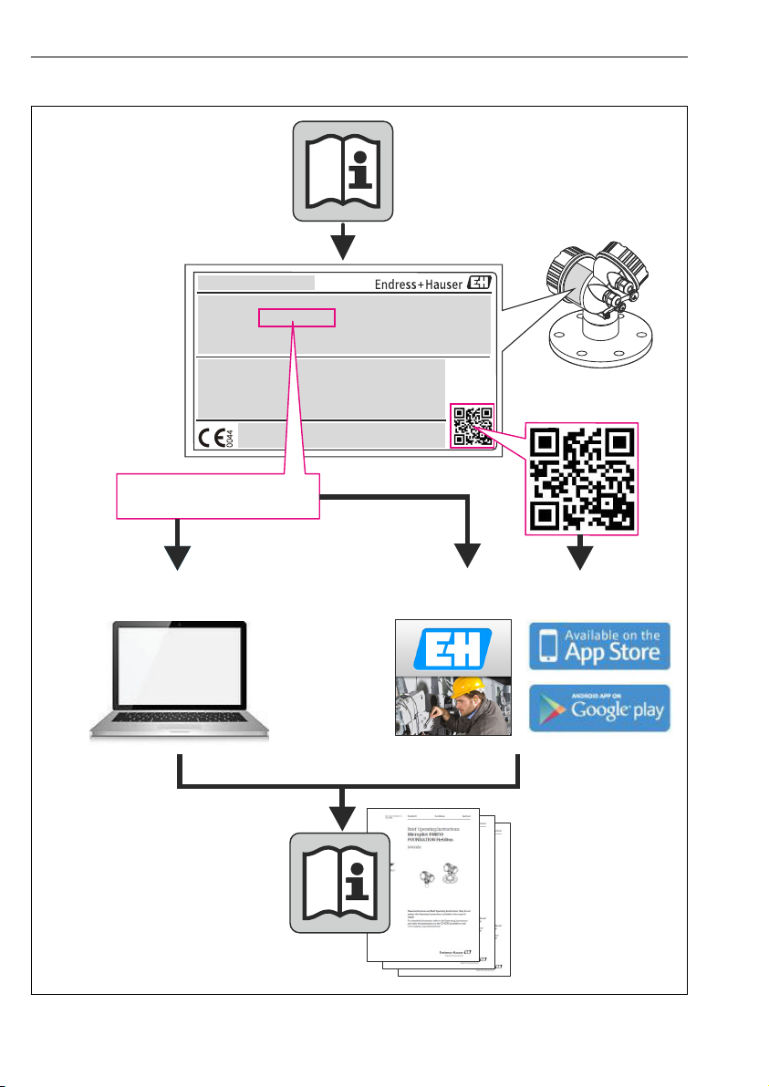
Detailed information about the device can be found in the
Operating Instructions and the other documentation:
• On the CD-ROM supplied (not included in the delivery for all
device versions).
• Available for all device versions via:
– Internet: www.endress.com/deviceviewer
– Smart phone/tablet: Endress+Hauser Operations App
Page 2
TAG No.: XXX000
Ser. No.: X000X000000
Order code 00X00-XXXX0XX0XXX
www.endress.com/deviceviewer Endress+Hauser Operations App
Serial number
Proline Promag H 100
2 Endress+Hauser
A0023555
Page 3

Proline Promag H 100 Table of contents
Table of contents
1 Document information ........................................................... 4
1.1 Symbols used ........................................................................ 4
2 Basic safety instructions ......................................................... 6
2.1 Requirements for the personnel ........................................................... 6
2.2 Designated use ....................................................................... 6
2.3 Workplace safety ...................................................................... 7
2.4 Operational safety ..................................................................... 7
2.5 Product safety ........................................................................ 7
2.6 IT security ........................................................................... 8
3 Product description .............................................................. 9
3.1 Product design ....................................................................... 9
4 Incoming acceptance and product identification ................................. 11
4.1 Incoming acceptance .................................................................. 11
4.2 Product identification ................................................................. 12
5 Storage and transport ........................................................... 12
5.1 Storage conditions .................................................................... 12
5.2 Transporting the product ............................................................... 13
6 Mounting ....................................................................... 14
6.1 Installation conditions ................................................................. 14
6.2 Mounting the measuring device .......................................................... 18
6.3 Post-installation check ................................................................. 24
7 Electrical connection ............................................................ 24
7.1 Connection conditions ................................................................. 24
7.2 Connecting the measuring device ......................................................... 33
7.3 Hardware settings .................................................................... 37
7.4 Ensuring the degree of protection ........................................................ 41
7.5 Post-connection check ................................................................. 42
8 Operation options .............................................................. 43
8.1 Structure and function of the operating menu ................................................ 43
8.2 Access to the operating menu via the Web browser ............................................ 43
8.3 Access to the operating menu via the operating tool ........................................... 47
9 System integration .............................................................. 47
10 Commissioning ................................................................. 48
10.1 Function check ...................................................................... 48
10.2 Establishing a connection via FieldCare .................................................... 48
10.3 Configuring the device address via software ................................................. 48
10.4 Configuring the measuring device ........................................................ 49
10.5 Defining the tag name ................................................................. 49
10.6 Protecting settings from unauthorized access ................................................ 49
11 Diagnostic information ......................................................... 52
Endress+Hauser 3
Page 4
Document information Proline Promag H 100
DANGER
WARNING
CAUTION
NOTICE
1 Document information
1.1 Symbols used
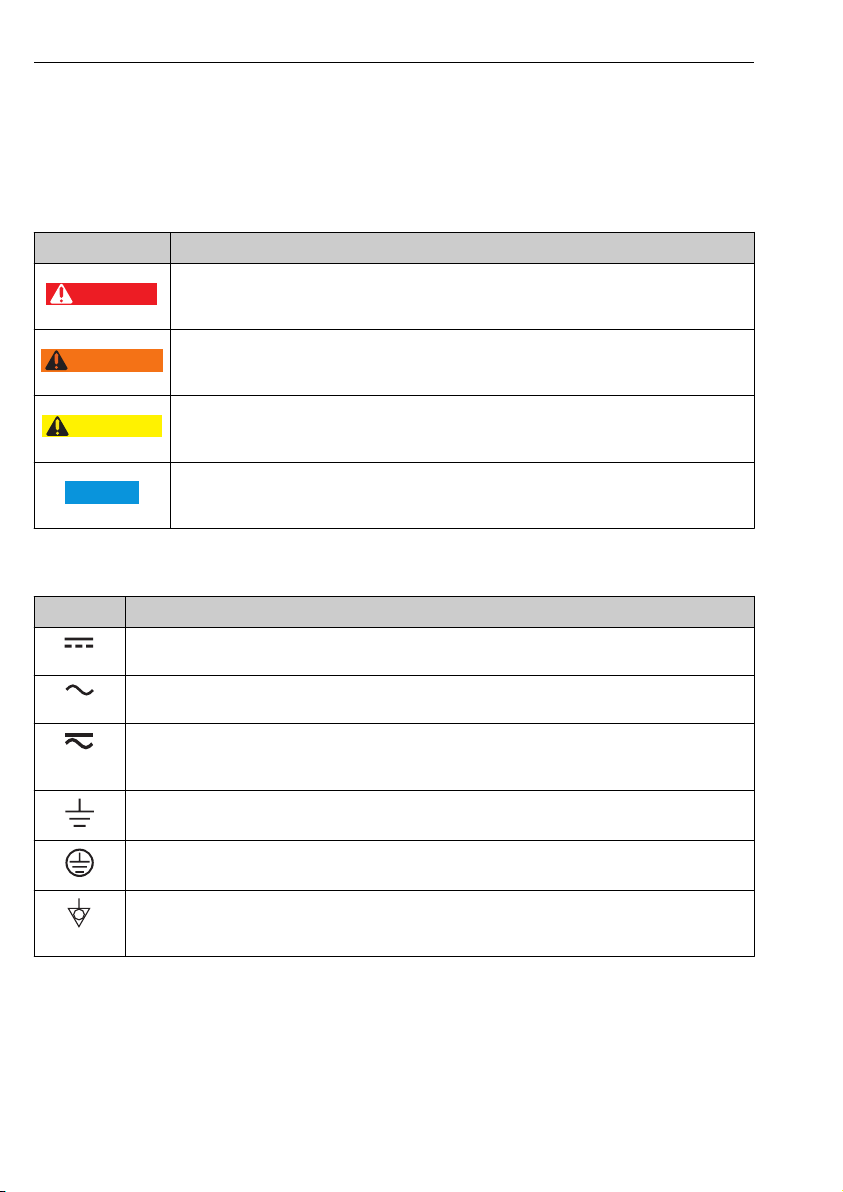
1.1.1 Safety symbols
Symbol Meaning
DANGER!
This symbol alerts you to a dangerous situation. Failure to avoid this situation will result in
serious or fatal injury.
WARNING!
This symbol alerts you to a dangerous situation. Failure to avoid this situation can result in
serious or fatal injury.
CAUTION!
This symbol alerts you to a dangerous situation. Failure to avoid this situation can result in
minor or medium injury.
NOTE!
This symbol contains information on procedures and other facts which do not result in personal
injury.
1.1.2 Electrical symbols
Symbol Meaning
Direct current
A terminal to which DC voltage is applied or through which direct current flows.
Alternating current
A terminal to which alternating voltage is applied or through which alternating current flows.
Direct current and alternating current
• A terminal to which alternating voltage or DC voltage is applied.
• A terminal through which alternating current or direct current flows.
Ground connection
A grounded terminal which, as far as the operator is concerned, is grounded via a grounding system.
Protective ground connection
A terminal which must be connected to ground prior to establishing any other connections.
Equipotential connection
A connection that has to be connected to the plant grounding system: This may be a potential
equalization line or a star grounding system depending on national or company codes of practice.
4 Endress+Hauser
Page 5
Proline Promag H 100 Document information
,…,
,…,
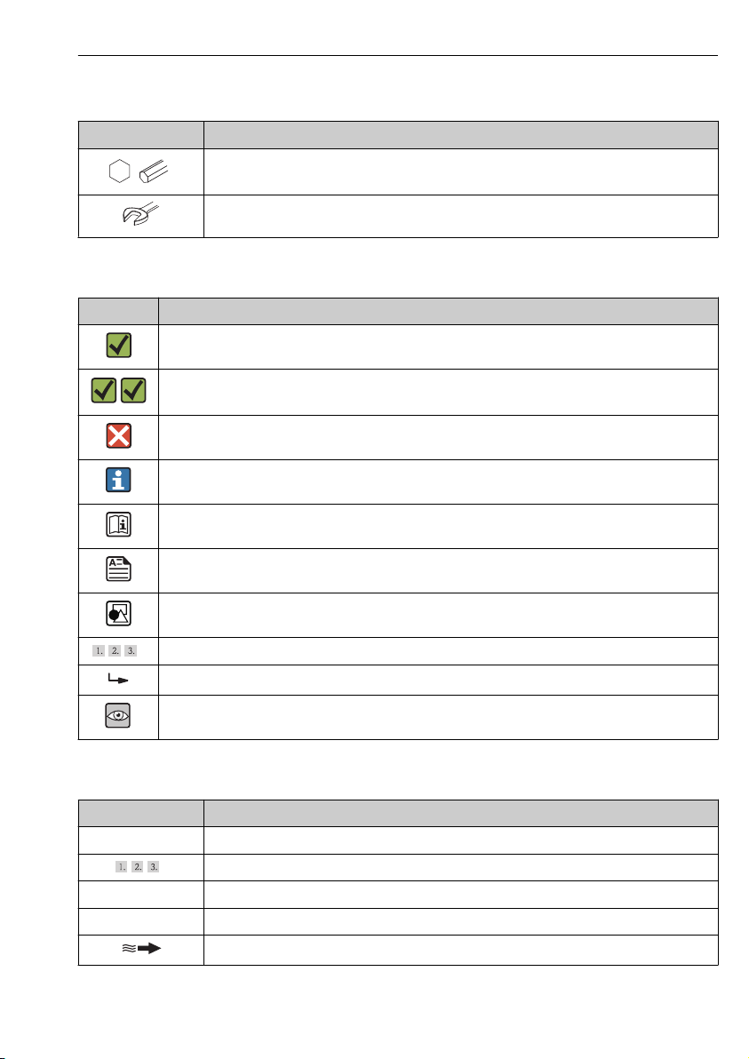
1.1.3 Tool symbols
Symbol Meaning
Allen key
Open-ended wrench
1.1.4 Symbols for certain types of information
Symbol Meaning
Permitted
Indicates procedures, processes or actions that are permitted.
Preferred
Indicates procedures, processes or actions that are preferred.
Forbidden
Indicates procedures, processes or actions that are forbidden.
Tip
Indicates additional information.
Reference to documentation
Refers to the corresponding device documentation.
Reference to page
Refers to the corresponding page number.
Reference to graphic
Refers to the corresponding graphic number and page number.
Series of steps
Result of a sequence of actions
Visual inspection
1.1.5 Symbols in graphics
Symbol Meaning
1, 2, 3,... Item numbers
Series of steps
A, B, C, ... Views
A-A, B-B, C-C, ... Sections
Flow direction
Endress+Hauser 5
Page 6

Basic safety instructions Proline Promag H 100
-
.
Symbol Meaning
Hazardous area
Indicates a hazardous area.
Safe area (non-hazardous area)
Indicates the non-hazardous area.
2 Basic safety instructions
2.1 Requirements for the personnel
The personnel must fulfill the following requirements for its tasks:
Trained, qualified specialists must have a relevant qualification for this specific function
‣
and task
Are authorized by the plant owner/operator
‣
Are familiar with federal/national regulations
‣
Before beginning work, the specialist staff must have read and understood the instructions
‣
in the Operating Instructions and supplementary documentation as well as in the
certificates (depending on the application)
Following instructions and basic conditions
‣
2.2 Designated use
Application and media
Depending on the version ordered, the measuring device can also measure potentially
explosive, flammable, poisonous and oxidizing media.
Measuring devices for use in hazardous areas, in hygienic applications or in applications
where there is an increased risk due to process pressure, are labeled accordingly on the
nameplate.
To ensure that the measuring device remains in proper condition for the operation time:
Only use the measuring device in full compliance with the data on the nameplate and the
‣
general conditions listed in the Operating Instructions and supplementary documentation.
Based on the nameplate, check whether the ordered device is permitted for the intended
‣
use in the hazardous area (e.g. explosion protection, pressure vessel safety).
Use the measuring device only for media against which the process-wetted materials are
‣
adequately resistant.
If the measuring device is not operated at atmospheric temperature, compliance with the
‣
relevant basic conditions specified in the associated device documentation is absolutely
essential: "Device documentation" section (Verweisziel existiert nicht, aber
@y.link.required='true').
Incorrect use
Non-designated use can compromise safety. The manufacturer is not liable for damage caused
by improper or non-designated use.
6 Endress+Hauser
Page 7

Proline Promag H 100 Basic safety instructions
WARNING
L
Danger of breakage of the sensor due to corrosive or abrasive fluids!
Verify the compatibility of the process fluid with the sensor material.
‣
Ensure the resistance of all fluid-wetted materials in the process.
‣
Observe the specified pressure and temperature range.
‣
Verification for borderline cases:
For special fluids and fluids for cleaning, Endress+Hauser is glad to provide assistance in
‣
verifying the corrosion resistance of fluid-wetted materials, but does not accept any
warranty or liability as minute changes in the temperature, concentration or level of
contamination in the process can alter the corrosion resistance properties.
Residual risks
The external surface temperature of the housing can increase by max. 10 K due to the power
consumption of the electronic components. Hot process fluids passing through the measuring
device will further increase the surface temperature of the housing. The surface of the sensor,
in particular, can reach temperatures which are close to the fluid temperature.
Possible burn hazard due to fluid temperatures!
For elevated fluid temperature, ensure protection against contact to prevent burns.
‣
2.3 Workplace safety
For work on and with the device:
Wear the required personal protective equipment according to federal/national
‣
regulations.
For welding work on the piping:
Do not ground the welding unit via the measuring device.
‣
If working on and with the device with wet hands:
It is recommended to wear gloves on account of the higher risk of electric shock.
‣
2.4 Operational safety
Risk of injury.
Operate the device in proper technical condition and fail-safe condition only.
‣
The operator is responsible for interference-free operation of the device.
‣
2.5 Product safety
This measuring device is designed in accordance with good engineering practice to meet stateof-the-art safety requirements, has been tested, and left the factory in a condition in which it
is safe to operate.
It meets general safety standards and legal requirements. It also complies with the EC
directives listed in the device-specific EC Declaration of Conformity. Endress+Hauser confirms
this by affixing the CE mark to the device.
Endress+Hauser 7
Page 8

Basic safety instructions Proline Promag H 100
2.6 IT security
We only provide a warranty if the device is installed and used as described in the Operating
Instructions. The device is equipped with security mechanisms to protect it against any
inadvertent changes to the device settings.
IT security measures in line with operators' security standards and designed to provide
additional protection for the device and device data transfer must be implemented by the
operators themselves.
8 Endress+Hauser
Page 9
Proline Promag H 100 Product description
3
2
1
4
5
6
7
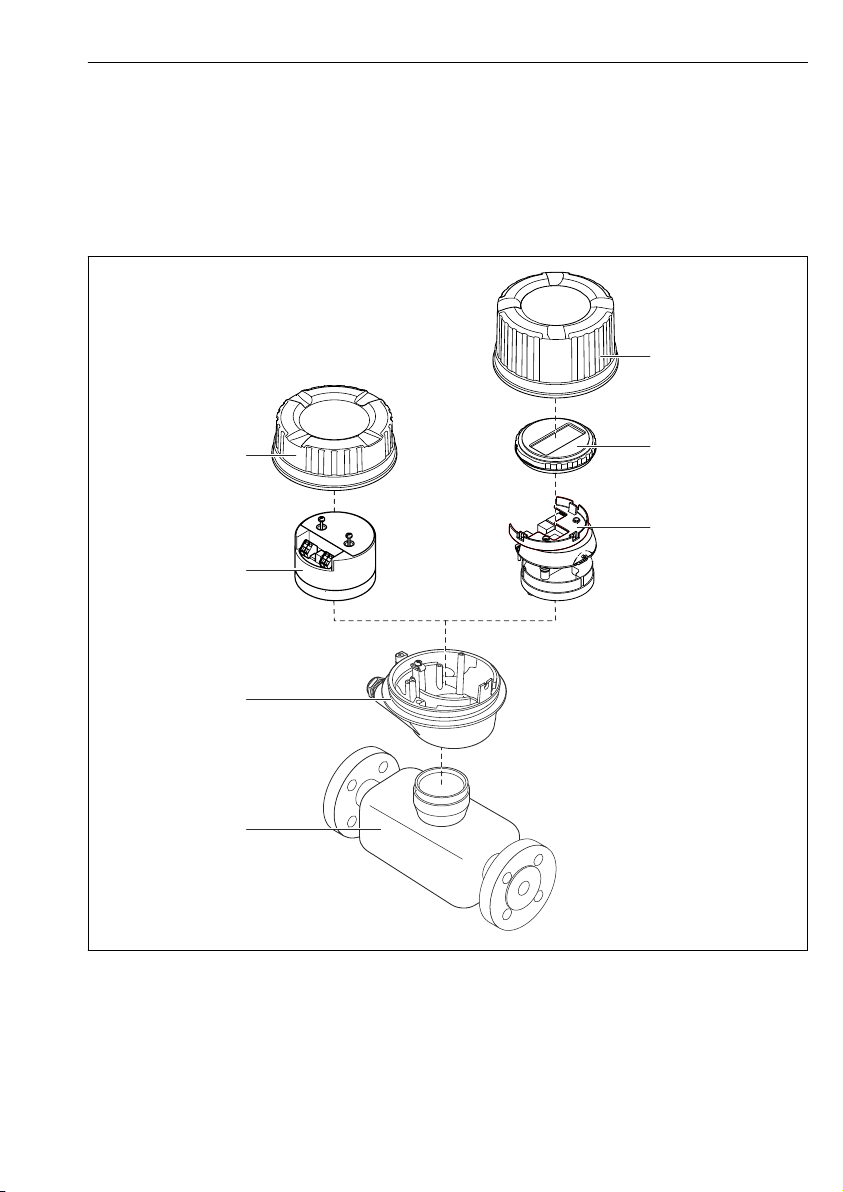
3 Product description
3.1 Product design
3.1.1 Device version with HART, EtherNet/IP and PROFIBUS DP communication types
1 Important components of a measuring device
1 Sensor
2 Transmitter housing
3 Main electronics module
4 Transmitter housing cover
A0023153
Endress+Hauser 9
Page 10
Product description Proline Promag H 100
3
2
1
4
5 Transmitter housing cover (version for optional onsite display)
6 Onsite display (optional)
7 Main electronics module (with bracket for optional onsite display)
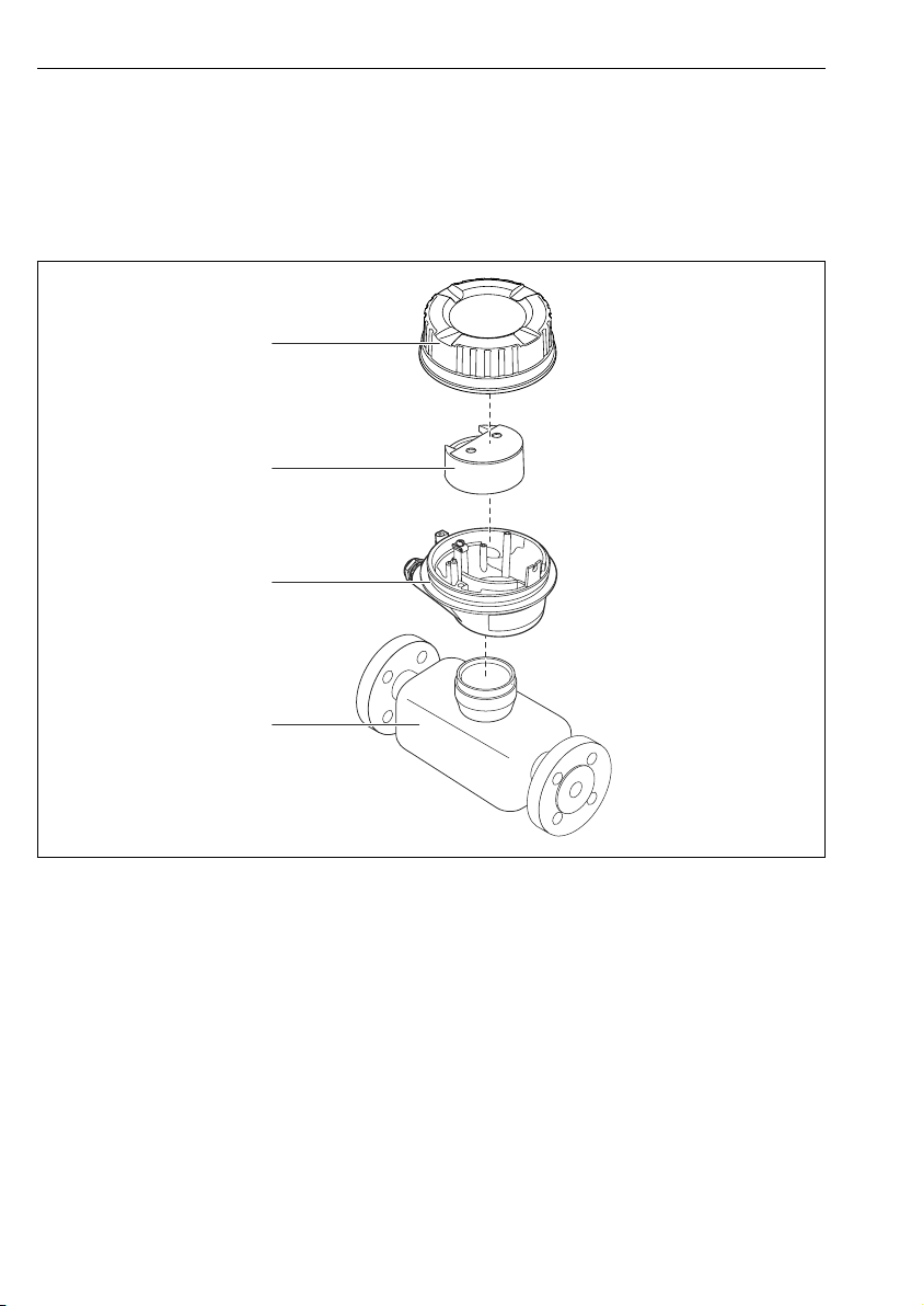
3.1.2 Device version with Modbus RS485 communication types
2 Important components of a measuring device
1 Sensor
2 Transmitter housing
3 Main electronics module
4 Transmitter housing cover
10 Endress+Hauser
A0017609
Page 11
Proline Promag H 100 Incoming acceptance and product identification
1
+
2
1
+
2
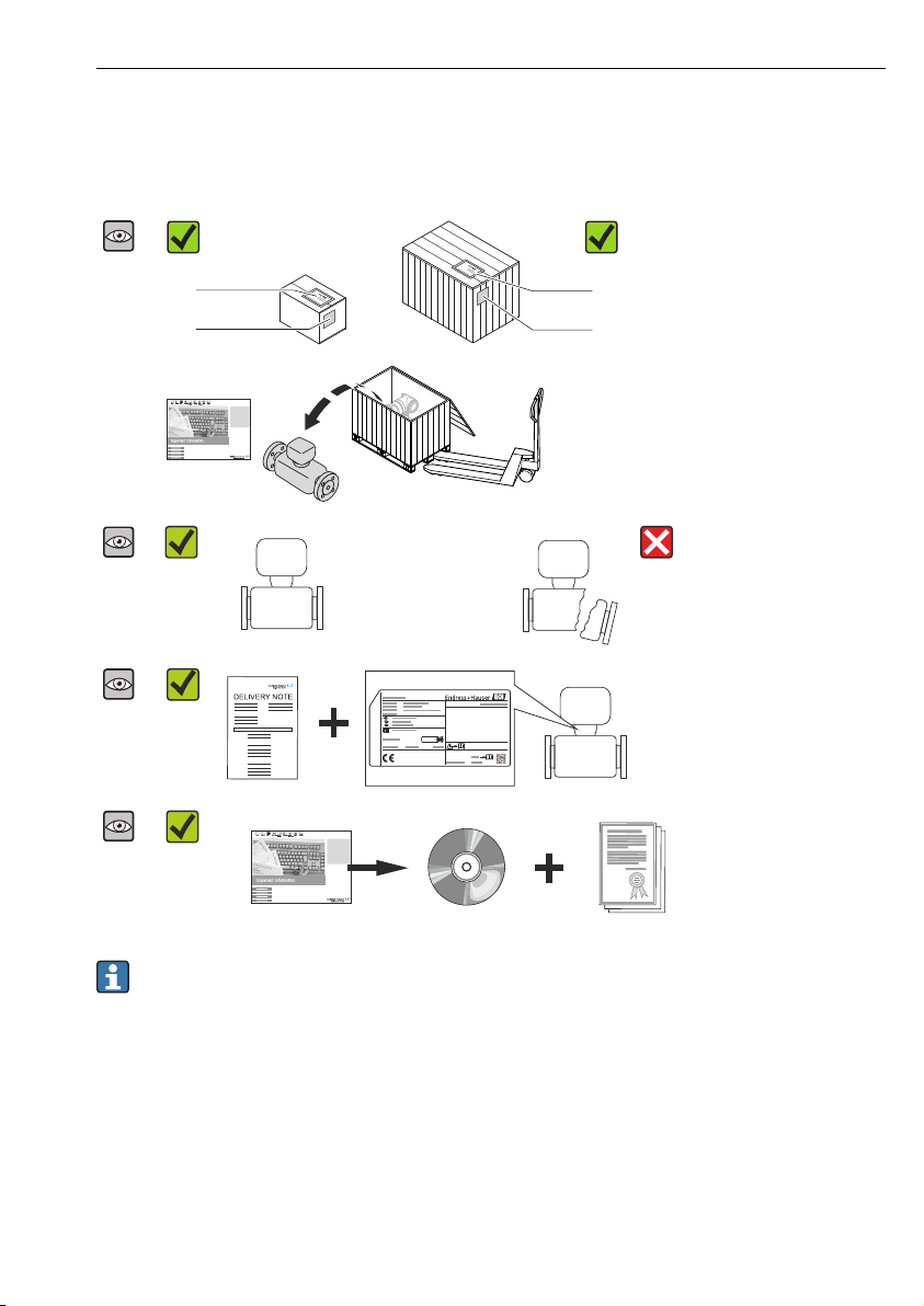
4 Incoming acceptance and product identification
4.1 Incoming acceptance
Are the order codes on the
delivery note (1) and the
product sticker (2) identical?
Are the goods undamaged?
Do the nameplate data match
the ordering information on
the delivery note?
Is the CD-ROM with the
Technical Documentation
(depends on device version)
and documents present?
• If one of the conditions is not satisfied, contact your Endress+Hauser Sales Center.
• Depending on the device version, the CD-ROM might not be part of the delivery! The
Technical Documentation is available via the Internet or via the Endress+Hauser
Operations App.
Endress+Hauser 11
Page 12
Storage and transport Proline Promag H 100
Order code:
Ext. ord. cd.:
Ser. no.:
Order code:
Ext. ord. cd.:
Ser. no.:
1
2
3
4
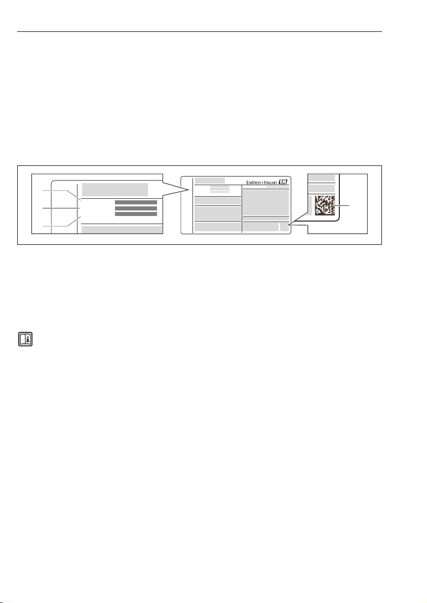
4.2 Product identification
The following options are available for identification of the measuring device:
• Nameplate specifications
• Order code with breakdown of the device features on the delivery note
• Enter serial numbers from nameplates in W@M Device Viewer
(www.endress.com/deviceviewer): All information about the measuring device is displayed.
• Enter the serial number from the nameplates into the Endress+Hauser Operations App or
scan the 2-D matrix code (QR code) on the nameplate with the Endress+Hauser Operations
App: all the information for the measuring device is displayed.
A0021952
3 Example of a nameplate
1 Order code
2 Serial number (Ser. no.)
3 Extended order code (Ext. ord. cd.)
4 2-D matrix code (QR code)
For detailed information on the breakdown of the specifications on the nameplate, see
the Operating Instructions for the device .
5 Storage and transport
5.1 Storage conditions
Observe the following notes for storage:
• Store in original packaging.
• Do not remove protective covers or protective caps installed on process connections.
• Protect from direct sunlight.
• Select a storage location where moisture cannot collect in the measuring device.
• Store in a dry and dust-free place.
• Do not store outdoors.
• Storage temperature→ 14
12 Endress+Hauser
Page 13
Proline Promag H 100 Storage and transport
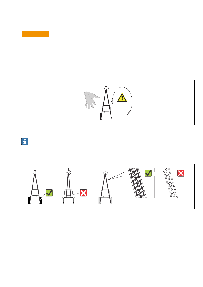
5.2 Transporting the product
WARNING
L
Center of gravity of the measuring device is higher than the suspension points of the
webbing slings.
Risk of injury if the measuring device slips.
Secure the measuring device from rotating or slipping.
‣
Observe the weight specified on the packaging (stick-on label).
‣
Observe the transport instructions on the stick-on label on the electronics compartment
‣
cover.
A0015606
• Transport the measuring device to the measuring point in the original packaging.
• Do not remove protective covers or protective caps installed on process connections.
They prevent mechanical damage to the sealing surfaces and contamination in the
measuring tube.
A0015604
Endress+Hauser 13
Page 14
Mounting Proline Promag H 100
h
h
2
1
6 Mounting
6.1 Installation conditions
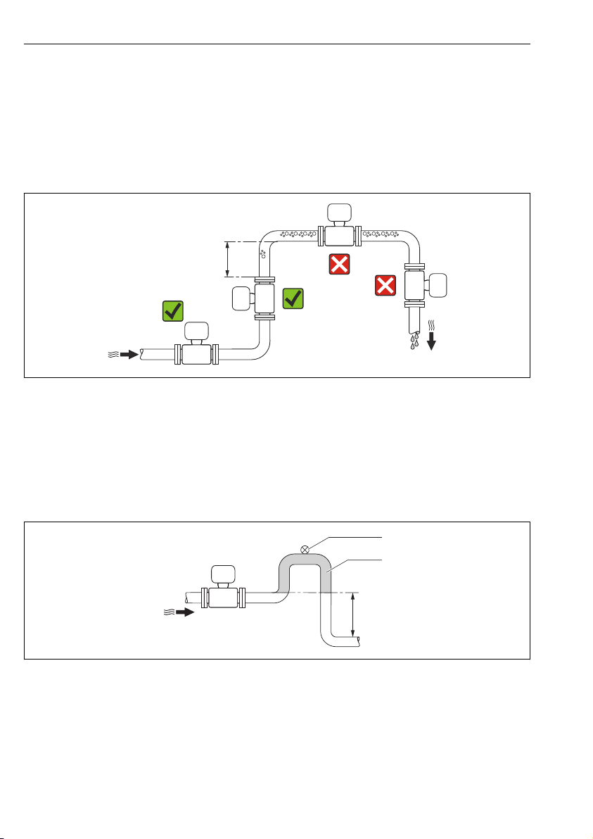
6.1.1 Mounting position
Mounting location
A0023343
h ≥ 2 × DN
Installation in down pipes
Install a siphon with a vent valve downstream of the sensor in down pipes whose length h ≥
5 m (16.4 ft). This precaution is to avoid low pressure and the consequent risk of damage to
the measuring tube. This measure also prevents the system losing prime.
A0017064
4 Installation in a down pipe
1 Vent valve
2 Pipe siphon
h Length of down pipe
14 Endress+Hauser
Page 15
Proline Promag H 100 Mounting
³ 5 × DN
³ 2 × DN
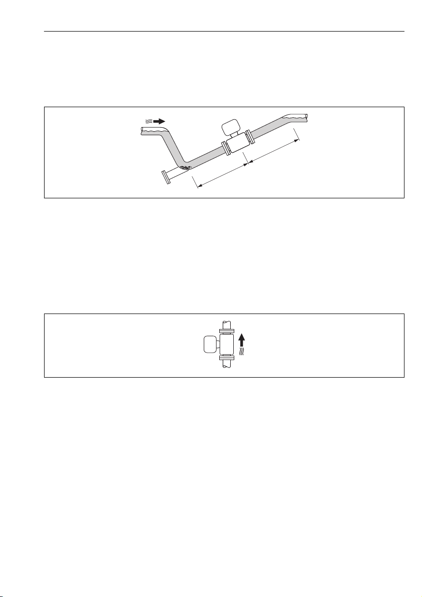
Installation in partially filled pipes
A partially filled pipe with a gradient necessitates a drain-type configuration. The empty pipe
detection (EPD) function offers additional protection by detecting empty or partially filled
pipes.
A0017063
Orientation
The direction of the arrow on the sensor nameplate helps you to install the sensor according
to the flow direction.
An optimum orientation position helps avoid gas and air accumulations and deposits in the
measuring tube.
Vertical
A0015591
This is the optimum for self-emptying piping systems and for use in conjunction with empty
pipe detection.
Endress+Hauser 15
Page 16
Mounting Proline Promag H 100
1
22
5 × DN≥
2 × DN≥
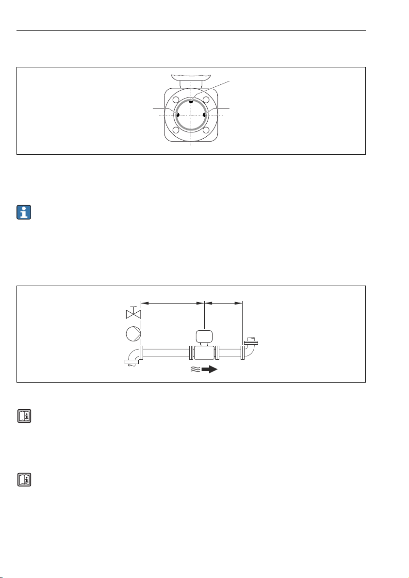
Horizontal
A0019602
1 EPD electrode for empty pipe detection
2 Measuring electrodes for signal detection
• The measuring electrode plane must be horizontal. This prevents brief insulation of
the two measuring electrodes by entrained air bubbles.
• The empty pipe detection only works if the transmitter housing is pointing upwards as
otherwise there is no guarantee that the empty pipe detection function will actually
respond to a partially filled or empty measuring tube.
Inlet and outlet runs
A0016275
For the dimensions and installation lengths of the device, see the "Technical Information"
document, "Mechanical construction" section
6.1.2 Requirements from environment and process
Ambient temperature range
For detailed information on the ambient temperature range, see the Operating
Instructions for the device (Verweisziel existiert nicht, aber @y.link.required='true')
If operating outdoors:
• Install the measuring device in a shady location.
• Avoid direct sunlight, particularly in warm climatic regions.
• Avoid direct exposure to weather conditions.
16 Endress+Hauser
Page 17
Proline Promag H 100 Mounting
L
Temperature tables
SI units
T
a
[°C]
30 50 95 130 150 150 150
50 – 95 130 150 150 150
60 – 95 110 110 110 110
T6
[85 °C]
T5
[100 °C]
T4
[135 °C]
T3
[200 °C]
T2
[300 °C]
T1
[450 °C]
US units
T
a
[°F]
86 122 203 266 302 302 302
122 – 203 266 302 302 302
140 – 203 230 230 230 230
T6
[185 °F]
T5
[212 °F]
T4
[275 °F]
T3
[392 °F]
T2
[572 °F]
T1
[842 °F]
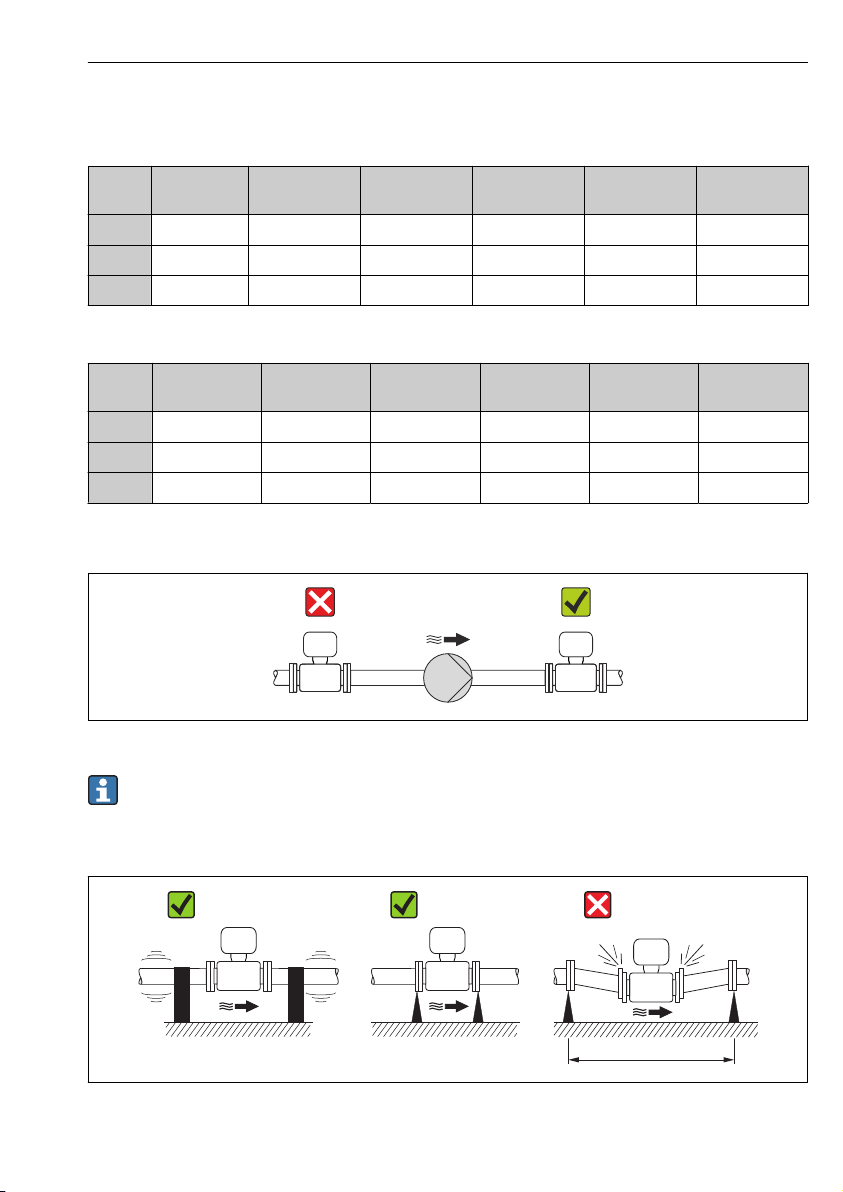
System pressure
A0015594
Furthermore, install pulse dampers if reciprocating, diaphragm or peristaltic pumps are
used.
Vibrations
A0016266
5 Measures to avoid device vibrations (L > 10 m (33 ft))
Endress+Hauser 17
Page 18

Mounting Proline Promag H 100
100
10
0.5
d / D
[mbar]
0.6 0.7 0.8 0.9
1 m/s
2 m/s
3 m/s
4 m/s
5 m/s
6 m/s
7 m/s
8 m/s
1
D
d
max. 8°
Adapters
A0016359
6.2 Mounting the measuring device
6.2.1 Required tools
For sensor
For flanges and other process connections:
• Screws, nuts, seals etc. are not included in the scope of supply and must be provided by the
customer.
• Appropriate mounting tools
6.2.2 Preparing the measuring device
1. Remove all remaining transport packaging.
2. Remove any protective covers or protective caps present from the sensor.
3. Remove stick-on label on the electronics compartment cover.
18 Endress+Hauser
Page 19

Proline Promag H 100 Mounting
6.2.3 Mounting the sensor
WARNING
L
Danger due to improper process sealing!
Ensure that the inside diameters of the gaskets are greater than or equal to that of the
‣
process connections and piping.
Ensure that the gaskets are clean and undamaged.
‣
Install the gaskets correctly.
‣
1. Ensure that the direction of the arrow on the sensor matches the flow direction of the
medium.
2. To ensure compliance with device specifications, install the measuring device between
the pipe flanges in a way that it is centered in the measurement section.
3. Install the measuring device or turn the transmitter housing so that the cable entries do
not point upwards.
A0013964
The sensor is supplied to order, with or without pre-installed process connections. Preinstalled process connections are firmly secured to the sensor by 4 or 6 hexagonal-headed
bolts.
The sensor may need to be supported or additionally secured depending on the
application and pipe length. In particular, it is absolutely essential to secure the sensor
additionally if plastic process connections are used. An appropriate wall mounting kit can
be ordered separately as an accessory from Endress+Hauser .
Endress+Hauser 19
Page 20

Mounting Proline Promag H 100
A
B
C
DN 2…25
(1/12…1 )"
DN 40…150
( …6 )1 ½ "
A0019804
6 Process connection seals
A Process connections with O-ring seal
B Process connections with aseptic molded seal, DN 2 to 25 (1/12 to 1")
C Process connections with aseptic molded seal, DN 40 to 150 (1 ½ to 6")
Welding the sensor into the pipe (welding connections)
WARNING
L
Risk of destroying the electronics!
Make sure that the welding system is not grounded via the sensor or transmitter.
‣
1. Tack-weld the sensor to secure it in the pipe. A suitable welding aid can be ordered
separately as an accessory .
2. Release the screws on the process connection flange and remove the sensor, along with
the seal, from the pipe.
3. Weld the process connection into the pipe.
4. Reinstall the sensor in the pipe, and in doing so make sure that the seal is clean and in
the right position.
• If thin-walled pipes carrying food are welded correctly, the seal is not damaged by the
heat even when mounted. Nevertheless it is advisable to remove the sensor and seal.
• It must be possible to open the pipe by approx. 8 mm (0.31 in) in total to permit
disassembly.
Cleaning with pigs
It is essential to take the internal diameters of the measuring tube and process connection
into account when cleaning with pigs. All the dimensions and lengths of the sensor and
transmitter are provided in the separate "Technical Information" document.
20 Endress+Hauser
Page 21

Proline Promag H 100 Mounting
Mounting the seals
Comply with the following instructions when installing seals:
• When mounting the process connections, make sure that the seals concerned are clean and
centered correctly.
• In the case of metal process connections, the screws must be tightened securely. The
process connection forms a metal connection with the sensor, which ensures a defined
compression of the seal.
• In the case of plastic process connections, comply with the max. screw tightening torques
for lubricated threads: 7 Nm (5.2 lbf ft). In the case of plastic flanges, always insert a seal
between the connection and the counterflange.
• Depending on the application the seals should be replaced periodically, particularly if
molded seals are used (aseptic version)! The interval between changes depends on the
frequency of the cleaning cycles, the cleaning temperature and the medium temperature.
Replacement seals can be ordered as an accessory .
Mounting grounding rings (DN 2 to 25 (1/12 to 1"))
Pay attention to the information on potential equalization → 35.
In the case of plastic process connections (e.g. flange connections or adhesive fittings),
additional ground rings must be used to ensure the potential between the sensor and fluid is
matched. If grounding rings are not installed, this can affect the measuring accuracy or cause
the destruction of the sensor as a result of the electrochemical decomposition of the
electrodes.
• Depending on the option ordered, plastic disks are used instead of grounding rings on
some process connections. These plastic disks only act as "spacers" and do not have any
potential matching function. Furthermore, they also perform a significant sealing
function at the sensor/process connection interface. Therefore, in the case of process
connections without metal grounding rings, these plastic disks/seals should never be
removed and should always be installed!
• Grounding rings can be ordered separately as an accessory from Endress+Hauser .
When ordering make sure that the grounding rings are compatible with the material
used for the electrodes, as otherwise there is the danger that the electrodes could be
destroyed by electrochemical corrosion!
• Grounding rings, including seals, are mounted inside the process connections.
Therefore the installation length is not affected.
Endress+Hauser 21
Page 22

Mounting Proline Promag H 100
1
3
2
4
2
A0002651
7 Installing grounding rings
1 Hexagonal-headed bolts of process connection
2 O-ring seals
3 Grounding ring or plastic disk (spacer)
4 Sensor
1. Release the 4 or 6 hexagonal-headed bolts (1) and remove the process connection from
the sensor (4).
2. Remove the plastic disk (3), along with the two O-ring seals (2), from the process
connection.
3. Place the first O-ring seal (2) back into the groove of the process connection.
4. Fit the metal grounding ring (3) in the process connection as illustrated.
5. Place the second O-ring seal (2) into the groove of the grounding ring.
6. Mount the process connection back on the sensor. In doing so, make sure you comply
with the max. screw tightening torques for lubricated threads: 7 Nm (5.2 lbf ft)
6.2.4 Turning the display module
The display module can be turned to optimize display readability.
22 Endress+Hauser
Page 23

Proline Promag H 100 Mounting
1.
2.
3.
4.
5.
6.
7.
4.
4.
3 mm
1.
2.
3.
4.
5.
6.
3.
3. 3.
8 mm
Aluminum housing version, AlSi10Mg, coated
A0023192
Compact and ultra-compact housing version, hygienic, stainless
A0023195
Endress+Hauser 23
Page 24

Electrical connection Proline Promag H 100
6.3 Post-installation check
Is the device undamaged (visual inspection)?
Does the measuring device conform to the measuring point specifications?
For example:
• Process temperature
• Process pressure (refer to the section on "Pressure-temperature ratings" in the "Technical Information"
document on the CD-ROM provided)
• Ambient temperature
• Measuring range
Has the correct orientation for the sensor been selected ?
• According to sensor type
• According to medium temperature
• According to medium properties (outgassing, with entrained solids)
Does the arrow on the sensor nameplate match the direction of flow of the fluid through the piping ?
Are the measuring point identification and labeling correct (visual inspection)?
Have the fixing screws been tightened with the correct tightening torque?
7 Electrical connection
The measuring device does not have an internal circuit breaker. For this reason, assign
the measuring device a switch or power-circuit breaker so that the power supply line can
be easily disconnected from the mains.
7.1 Connection conditions
7.1.1 Required tools
• For cable entries: Use corresponding tools
• For securing clamp (on aluminum housing): Allen screw3 mm
• For securing screw (for stainless steel housing): open-ended wrench 8 mm
• Wire stripper
• When using stranded cables: crimping tool for ferrule
7.1.2 Requirements for connecting cable
The connecting cables provided by the customer must fulfill the following requirements.
Electrical safety
In accordance with applicable federal/national regulations.
Permitted temperature range
• –40 °C (–40 °F) to +80 °C (+176 °F)
• Minimum requirement: cable temperature range ≥ ambient temperature +20 K
Power supply cable
Standard installation cable is sufficient.
24 Endress+Hauser
Page 25

Proline Promag H 100 Electrical connection
Signal cable
Current output
For 4-20 mA HART: Shielded cable recommended. Observe grounding concept of the plant.
Pulse/frequency/switch output
Standard installation cable is sufficient.
PROFIBUS DP
The IEC 61158 standard specifies two types of cable (A and B) for the bus line which can be
used for every transmission rate. Cable type A is recommended.
Cable type A
Characteristic impedance 135 to 165 Ωat a measuring frequency of 3 to 20 MHz
Cable capacitance <30 pF/m
Wire cross-section
Cable type Twisted pairs
Loop resistance ≤110 Ω/km
Signal damping Max. 9 dB over the entire length of the cable cross-section
Shielding Copper braided shielding or braided shielding with foil shield. When grounding the
>0.34 mm2 (22 AWG)
cable shield, observe the grounding concept of the plant.
Modbus RS485
The EIA/TIA-485 standard specifies two types of cable (A and B) for the bus line which can be
used for every transmission rate. Cable type A is recommended.
Cable type A
Characteristic impedance 135 to 165 Ωat a measuring frequency of 3 to 20 MHz
Cable capacitance <30 pF/m
Wire cross-section
Cable type Twisted pairs
Loop resistance ≤110 Ω/km
Signal damping Max. 9 dB over the entire length of the cable cross-section
Shielding Copper braided shielding or braided shielding with foil shield. When grounding the
Endress+Hauser 25
>0.34 mm2 (22 AWG)
cable shield, observe the grounding concept of the plant.
Page 26

Electrical connection Proline Promag H 100
EtherNet/IP
The standard ANSI/TIA/EIA-568-B.2 Annex specifies CAT 5 as the minimum category for a
cable used for EtherNet/IP. CAT 5e and CAT 6 are recommended.
For more information on planning and installing EtherNet/IP networks, please refer to
the "Media Planning and Installation Manual. EtherNet/IP" of the ODVA Organization.
Cable diameter
• Cable glands supplied:
M20 × 1.5 with cable 6 to 12 mm (0.24 to 0.47 in)
• Spring terminals:
Wire cross-sections 0.5 to 2.5 mm2 (20 to 14 AWG)
26 Endress+Hauser
Page 27

Proline Promag H 100 Electrical connection
L
L
26
27
+
_
24
25
1
2
+
_
+
_
1
2
3
7.1.3 Terminal assignment
Transmitter
Connection version 4-20 mA HART with pulse/frequency/switch output
Order code for "Output", option B
Depending on the housing version, the transmitters can be ordered with terminals or device
plugs.
A0016888
8 Terminal assignment 4-20 mA HART with pulse/frequency/switch output
1 Power supply: DC 24 V
2 Output 1: 4-20 mA HART (active)
3 Output 2: pulse/frequency/switch output (passive)
Terminal number
Order code for
"Output"
Option B DC 24 V 4-20 mA HART (active) Pulse/frequency/switch
Order code for "Output":
Option B: 4-20 mA HART with pulse/frequency/switch output
Endress+Hauser 27
Power supply Output 1 Output 2
2 (L-) 1 (L+) 27 (–) 26 (+) 25 (–) 24 (+)
output (passive)
Page 28

Electrical connection Proline Promag H 100
L
L
26
27BA
1
2
+
_
1
2
PROFIBUS DP connection version
For use in the non-hazardous area and Zone 2/Div. 2.
Order code for "Output", option L
Depending on the housing version, the transmitters can be ordered with terminals or device
plugs.
A0022716
9 PROFIBUS DP terminal assignment
1 Power supply: DC 24 V
2 PROFIBUS DP
Terminal number
Order code for
"Output"
Option L DC 24 V B A
Order code for "Output":
Option L: PROFIBUS DP, for use in non-hazardous areas and Zone 2/div. 2
28 Endress+Hauser
Power supply Output
2 (L-) 1 (L+) 26 (RxD/TxD-P) 27 (RxD/TxD-N)
Page 29

Proline Promag H 100 Electrical connection
L
L
26
27AB
1
2
+
_
1
2
Modbus RS485 connection version
Order code for "Output", option M
Depending on the housing version, the transmitters can be ordered with terminals or device
plugs.
A0019528
10 Modbus RS485 terminal assignment
1 Power supply: DC 24 V
2 Modbus RS485
Terminal number
Order code for
"Output"
Option M DC 24 V Modbus RS485
Order code for "Output":
Option M: Modbus RS485
Power supply Output
2 (L-) 1 (L+) 27 (B) 26 (A)
Endress+Hauser 29
Page 30

Electrical connection Proline Promag H 100
L
L
1
2
+
_
1
2
1
2
4
3
5
EtherNet/IP connection version
Order code for "Output", option N
Depending on the housing version, the transmitters can be ordered with terminals or device
plugs.
A0017054
11 EtherNet/IP terminal assignment
1 Power supply: DC 24 V
2 EtherNet/IP
Terminal number
Order code for
"Output"
Option N DC 24 V EtherNet/IP
Order code for "Output":
Option N: EtherNet/IP
Power supply Output
2 (L-) 1 (L+) Device plug M12x1
7.1.4 Pin assignment, device plug
Supply voltage
For all connection versions (device side)
Pin Assignment Coding Plug/socket
1 L+ DC 24 V A Plug
2
3
4 L- DC 24 V
5 Grounding/shielding
A0016809
30 Endress+Hauser
Page 31

Proline Promag H 100 Electrical connection
3
2
4
1
5
3
2
4
1
5
3
2
4
1
5
4-20 mA HART with pulse/frequency/switch output
Device plug for signal transmission (device side)
Pin Assignment Coding Plug/socket
1 + 4-20 mA HART (active) A Socket
2 - 4-20 mA HART (active)
3 + Pulse/frequency/switch output (passive)
4 - Pulse/frequency/switch output (passive)
5 Grounding/shielding
A0016810
PROFIBUS DP
For use in the non-hazardous area and Zone 2/Div. 2.
Device plug for signal transmission (device side)
Pin Assignment Coding Plug/socket
1 B Socket
2 A PROFIBUS DP
3
4 B PROFIBUS DP
5 Grounding/shielding
A0016811
MODBUS RS485
Device plug for signal transmission (device side)
Pin Assignment Coding Plug/socket
1 B Socket
2 A Modbus RS485
3
4 B Modbus RS485
5 Grounding/shielding
A0016811
Endress+Hauser 31
Page 32

Electrical connection Proline Promag H 100
3
2
4
1
EtherNet/IP
Device plug for signal transmission (device side)
Pin Assignment Coding Plug/socket
1 + Tx D Socket
2 + Rx
3 - Tx
4 - Rx
A0016812
7.1.5 Shielding and grounding
The shielding and grounding concept requires compliance with the following:
• Electromagnetic compatibility (EMC)
• Explosion protection
• Personal protection equipment
• National installation regulations and guidelines
• Observe cable specification → 24.
• Keep the stripped and twisted lengths of cable shield to the ground terminal as short as
possible.
• Seamless cable shielding.
Grounding of the cable shield
To comply with EMC requirements:
• Ensure the cable shield is grounded to the potential matching line at multiple points.
• Connect every local ground terminal to the potential matching line.
NOTICE
In systems without potential matching, the multiple grounding of the cable shield causes
mains frequency equalizing currents!
Damage to the bus cable shield.
Only ground the bus cable shield to either the local ground or the protective ground at one
‣
end.
7.1.6 Preparing the measuring device
1. Remove dummy plug if present.
2.
NOTICE
Insufficient sealing of the housing!
Operational reliability of the measuring device could be compromised.
Use suitable cable glands corresponding to the degree of protection.
‣
If measuring device is delivered without cable glands:
Provide suitable cable gland for corresponding connecting cable → 24.
3. If measuring device is delivered with cable glands:
Observe cable specification → 24.
32 Endress+Hauser
Page 33

Proline Promag H 100 Electrical connection
1 2 1 2 3 4
A B C
7.2 Connecting the measuring device
NOTICE
Limitation of electrical safety due to incorrect connection!
For use in potentially explosive atmospheres, observe the information in the device-specific
‣
Ex documentation.
7.2.1 Connecting the transmitter
The connection of the transmitter depends on the following order codes:
• Housing version: compact or ultra-compact
• Connection version: device plug or terminals
A0016924
12 Device versions and connection versions
A Housing version: compact, aluminum coated
B Housing version: compact hygienic, stainless
1 Cable entry or device plug for signal transmission
2 Cable entry or device plug for supply voltage
C Housing version: ultra-compact hygienic, stainless, M12 device plug
3 Device plug for signal transmission
4 Device plug for supply voltage
Endress+Hauser 33
Page 34

Electrical connection Proline Promag H 100
10 (0.4)
mm (in)
1 2
3
2
1
2
1
2
3
8 mm
3 mm
8 mm
13 Device versions with connection examples
1 Cable
2 Device plug for signal transmission
3 Device plug for supply voltage
Depending on the housing version disconnect the local display from the main electronics
module: Operating Instructions for the device .
Connect the cable in accordance with the terminal assignment or the device plug pin
‣
assignment .
34 Endress+Hauser
A0017844
Page 35

Proline Promag H 100 Electrical connection
7.2.2 Ensuring potential equalization
CAUTION
L
Electrode damage can result in the complete failure of the device!
Make sure that the fluid and sensor have the same electrical potential.
‣
Pay attention to internal grounding concepts in the company.
‣
Pay attention to the pipe material or grounding.
‣
Connection examples for standard situations
Metal process connections
Potential matching usually takes place via the metallic process connections in contact with
medium which are directly mounted on the measuring transmitter. This usually means that
additional potential matching measures are unnecessary.
Connection example in special situations
Plastic process connections
In the case of plastic process connections, additional grounding rings or process connections
with an integrated grounding electrode must be used to ensure potential matching between
the sensor and the fluid. If there is no potential matching, this can affect the measuring
accuracy or cause the destruction of the sensor as a result of the electrochemical
decomposition of the electrodes.
Note the following when using grounding rings:
• Depending on the option ordered, plastic disks are used instead of grounding rings on some
process connections. These plastic disks only act as "spacers" and do not have any potential
matching function. Furthermore, they also perform a significant sealing function at the
sensor/connection interface. Therefore, in the case of process connections without metal
grounding rings, these plastic disks/seals should never be removed and should always be
installed!
• Grounding rings can be ordered separately as an accessory from Endress+Hauser . When
ordering make sure that the grounding rings are compatible with the material used for the
electrodes, as otherwise there is the danger that the electrodes could be destroyed by
electrochemical corrosion!
• Grounding rings, including seals, are mounted inside the process connections. Therefore the
installation length is not affected.
Endress+Hauser 35
Page 36

Electrical connection Proline Promag H 100
1
3
2
4
2
Potential equalization via additional grounding ring
A0002651
1 Hexagonal-headed bolts of process connection
2 O-ring seals
3 Plastic disk (spacer) or grounding ring
4 Sensor
36 Endress+Hauser
Page 37

Proline Promag H 100 Electrical connection
2
1
3
4
Potential equalization via grounding electrodes on process connection
A0017293
1 Hexagonal-headed bolts of process connection
2 Integrated grounding electrodes
3 O-ring seal
4 Sensor
7.3 Hardware settings
7.3.1 Setting the device address
EtherNet/IP
The IP address of the measuring device can be configured for the network via DIP switches.
Addressing data
1st octet 2nd octet 3rd octet 4th octet
192. 168. 1. XXX
Can only be configured via software addressing Can be configured via
Endress+Hauser 37
IP address and configuration options
↓ ↓
software addressing
and hardware
addressing
Page 38

Electrical connection Proline Promag H 100
OFF ON
1
2
3
4
5
6
7
8
9
10
1
2
4
8
16
32
64
128
- Write protection
- Default Ethernet
network settings
IP 192.168.1.212
IP Address setting
(last octet)
IP address range 1 to 254 (4th octet)
IP address broadcast 255
Addressing mode ex works Software addressing; all DIP switches for hardware addressing are set to OFF.
IP address ex works DHCP server active
For device addressing via software → 48
Setting the address
A0017913
Set the desired IP address using the corresponding DIP switches on the I/O electronics
‣
module.
Hardware addressing with the configured IP address is enabled after 10 s.
PROFIBUS DP
The address must always be configured for a PROFIBUS DP/PA device. The valid address
range is between 1 and 126. In a PROFIBUS DP/PA network, each address can only be
assigned once. If an address is not configured correctly, the device is not recognized by the
master. All measuring devices are delivered from the factory with the device address 126 and
with the software addressing method.
38 Endress+Hauser
Page 39

Proline Promag H 100 Electrical connection
OFF ON
1
2
3
4
5
6
7
8
9
10
1
2
4
8
16
32
64
- Write protection
- Not used
PROFIBUS
address
- Software addressing
Setting the address
A0021265
14 Addressing using DIP switches on the I/O electronics module
1. Disable software addressing via DIP switch 8 (OFF).
2. Set the desired device address via the corresponding DIP switches.
Example → 14, 39: 1 + 16 + 32 = device address 49
The device demands rebooting after 10 s. After rebooting, hardware addressing is
enabled with the configured IP address.
7.3.2 Enabling the terminating resistor
PROFIBUS DP
To avoid incorrect communication transmission caused by impedance mismatch, terminate
the PROFIBUS DP cable correctly at the start and end of the bus segment.
• If the device is operated with a baud rate of 1.5 MBaud and under:
For the last transmitter on the bus, terminate via DIP switch 2 (bus termination) and DIP
switch 1 and 3 (bus polarization). Setting: ON – ON – ON → 15, 40.
• For baud rates > 1.5 MBaud:
Due to the capacitance load of the user and the line reflections generated as a result, ensure
that an external bus terminator is used.
It is generally advisable to use an external bus terminator as the entire segment can fail
if a device that is terminated internally is defective.
Endress+Hauser 39
Page 40

Electrical connection Proline Promag H 100
390 Ω
DIP 1
5V
26
27
220 Ω
DIP 2
0V
390 Ω
DIP 3
OFF ON
1
2
3
4
Bus polarisation
Bus termination
Bus polarisation
Not used
4.
1.
2.
3.
15 Termination using DIP switches on the I/O electronics module (for baud rates < 1.5 MBaud)
Modbus RS485
To avoid incorrect communication transmission caused by impedance mismatch, terminate
the Modbus RS485 cable correctly at the start and end of the bus segment.
40 Endress+Hauser
A0021274
Page 41

Proline Promag H 100 Electrical connection
2 - Not used
1 - Write protection
4 - Bus termination
3 - Not used
OFFON
26
27AB
220 W
If the transmitter is used in the non-hazardous area or Zone 2/Div. 2
A0017610
16 Terminating resistor can be enabled via DIP switch on the main electronics module
7.4 Ensuring the degree of protection
The measuring device fulfills all the requirements for the IP66/67 degree of protection, Type
4X enclosure.
To guarantee IP66/67 degree of protection, Type 4X enclosure, carry out the following steps
after the electrical connection:
1. Check that the housing seals are clean and fitted correctly. Dry, clean or replace the
seals if necessary.
2. Tighten all housing screws and screw covers.
3. Firmly tighten the cable glands.
4. To ensure that moisture does not enter the cable entry, route the cable so that it loops
down before the cable entry ("water trap").
A0013960
5. Insert dummy plugs into unused cable entries.
Endress+Hauser 41
Page 42

Electrical connection Proline Promag H 100
7.5 Post-connection check
Are cables or the device undamaged (visual inspection)?
Do the cables comply with the requirements → 24?
Do the cables have adequate strain relief?
Are all the cable glands installed, firmly tightened and leak-tight? Cable run with "water trap" → 41 ?
Depending on the device version: are all the device plugs firmly tightened → 33?
• Does the supply voltage match the specifications on the transmitter nameplate ?
• For device version with Modbus RS485 intrinsically safe: does the supply voltage match the
specifications on the nameplate of the Safety Barrier Promass 100 ?
Is the terminal assignment or the pin assignment of the device plug correct?
• If supply voltage is present, is the power LED on the electronics module of the transmitter lit green
→ 9?
• For device version with Modbus RS485 intrinsically safe, if supply voltage is present, is the power LED
on the Safety Barrier Promass 100 lit → 9?
Is the potential equalization established correctly → 35?
Depending on the device version, is the securing clamp or fixing screw firmly tightened?
42 Endress+Hauser
Page 43

Proline Promag H 100 Operation options
!
Expert
Operating menu for experts
Language
Operation
Setup
Diagnostics
Operating menu for operators and maintenances
Operator
Maintenance
task-oriented
function-oriented
Expert
8 Operation options
8.1 Structure and function of the operating menu
8.1.1 Structure of the operating menu
17 Schematic structure of the operating menu
8.1.2 Operating philosophy
The individual parts of the operating menu are assigned to certain user roles. Each user role
corresponds to typical tasks within the device lifecycle.
For detailed information about the operating philosophy of the device, see the Operating
A0014058-EN
Instructions for the device (Verweisziel existiert nicht, aber @y.link.required='true').
8.2 Access to the operating menu via the Web browser
This type of access is available with the following device version:
Order code for "Output", option N: EtherNet/IP
Endress+Hauser 43
Page 44

Operation options Proline Promag H 100
OFF ON
1
2
3
4
5
6
7
8
9
10
1
2
4
8
16
32
64
128
- Write protection
- Default Ethernet
network settings
IP 192.168.1.212
IP Address setting
(last octet)
8.2.1 Function range
Thanks to the integrated Web server the device can be operated and configured via a Web
browser.
8.2.2 Prerequisites
Hardware
Connecting cable Standard Ethernet cable with RJ45 connector
Computer RJ45 interface
Measuring device: Web server must be enabled; factory setting: ON
IP address If the IP address of the device is not known, communication with the Web server
can be established via the standard IP address 192.168.1.212.
The DHCP function is enabled in the device at the factory, i.e. the device expects
an IP address to be assigned by the network. This function can be disabled and
the device can be set to the standard IP address 192.168.1.212: set switch DIP
switch No. 10 from OFF → ON.
• Once the DIP switch has been activated, the device must be restarted
before the device uses the standard IP address.
• If the standard IP address (DIP switch No. 10 = ON) is used, there is no
connection to the EtherNet/IP network.
Software of the computer
Web browsers supported • Microsoft Internet Explorer (min. 8.x)
Recommended operating systems • Windows XP
44 Endress+Hauser
• Mozilla Firefox
• Google chrome
• Windows 7
A0017965
Page 45

Proline Promag H 100 Operation options
User rights for TCP/IP settings User rights required for TCP/IP settings (e.g. for changes to IP address, subnet
Computer configuration • JavaScript is enabled
mask)
• If JavaScript cannot be enabled, enter http://XXX.XXX.X.XXX/basic.html in the
address line of the Web browser, e.g. http://192.168.1.212/basic.html. A
fully functional but simplified version of the operating menu structure starts
in the Web browser.
8.2.3 Establishing a connection
Configuring the Internet protocol of the computer
The following information refers to the default Ethernet settings of the device.
IP address of the device: 192.168.1.212 (factory setting)
IP address 192.168.1.XXX; for XXX all numerical values except: 0, 212 and 255 → e.g.
Subnet mask 255.255.255.0
Default gateway 192.168.1.212 or leave cells empty
192.168.1.213
1. Switch on the measuring device and connect to the computer via the cable .
2. If a 2nd network card is not used: all the applications on the notebook should be closed,
or all the applications that require the Internet or network, such as e-mail, SAP
applications, Internet or Windows Explorer, i.e. close all open Internet browsers.
3. Configure the properties of the Internet protocol (TCP/IP) as defined in the table above.
Starting the Web browser
1. Enter the IP address of the Web server in the address line of the Web browser:
192.168.1.212
2. If the IP address of the measuring device is known, enter the defined device address in
the address line of the Web browser. If it is unknown, set DIP switch No. 10 to ON,
restart the device and enter the standard IP address: 192.168.1.212 → 44.
The login page appears.
Endress+Hauser 45
Page 46

Operation options Proline Promag H 100
Device tag
Webserv.language
English
Ent. access code
Access stat.tool Maintenance
12
OK
2 4
6
5
1 32 4
6
5
1 32 4
6
5
1 32 4
6
5
1 32 4
6
5
1 3
A0017362
1 Device tag → 49
2 Picture of device
8.2.4 Logging on
Access code 0000 (factory setting); can be changed by customer → 49
8.2.5 User interface
1
Picture of device
2
Function row with 6 functions
3
Device tag
4
Header
5
Working area
6
Navigation area
46 Endress+Hauser
A0017757-EN
Page 47

Proline Promag H 100 System integration
Header
The following information appears in the header:
• Device tag → 49
• Device status with status signal
• Current measured values
Function row
Functions Meaning
Measured values The measured values of the device are displayed
Menu Access to the operating menu structure of the device, same as for the operating tool
Device status Displays the diagnostic messages currently pending, listed in order of priority
• Data exchange between PC and measuring device:
– Upload the configuration from the device (XML format, create configuration back-up)
– Save the configuration to the device (XML format, restore configuration)
Data management
Network
configuration
Logout End the operation and call up the login page
– Export the event list (.csv file)
– Export parameter settings (.csv file, create documentation of the measuring point
configuration)
– Export the Heartbeat verification log (PDF file, only available with the "Heartbeat
Verification" application package)
• Upload the device driver for system integration from the device
Configuration and checking of all the parameters required for establishing the connection to the
device:
• Network settings (e.g. IP address, MAC address)
• Device information (e.g. serial number, firmware version)
8.3 Access to the operating menu via the operating tool
For detailed information about access to the operating menu via operating tool, refer to
the Operating Instructions for the device (Verweisziel existiert nicht, aber
@y.link.required='true').
9 System integration
For information on system integration, see the Operating Instructions for the device
(Verweisziel existiert nicht, aber @y.link.required='true').
Applies only to device version with EtherNet/IP communication type
A detailed description of how to integrate the device into an automation system (e.g.
from Rockwell Automation) is available as a separate document: www.endress.com →
Select country → Automation → Digital Communication → Feldbus device
integration → EtherNet/IP
Endress+Hauser 47
Page 48

Commissioning Proline Promag H 100
10 Commissioning
10.1 Function check
Before commissioning the device, make sure that the post-installation and post-connection
checks have been performed.
• "Post-installation check" checklist → 24
• "Post-connection check" checklist → 42
10.2 Establishing a connection via FieldCare
• For FieldCare connection → 47
• For establishing a connection via FieldCare
10.3 Configuring the device address via software
In the "Communication" submenu the device address can be set.
Navigation
"Setup" menu → Communication → Device address
10.3.1 Ethernet network and Web server
When delivered, the measuring device has the following factory settings:
IP address 192.168.1.212
Subnet mask 255.255.255.0
Default gateway 192.168.1.212
• If hardware addressing is active, software addressing is disabled.
• If a switch is made to hardware addressing, the address configured via software
addressing is retained for the first 9 places (the first three octets).
If the IP address of the device is not known, the device address currently configured can
be read out: Operating Instructions for the device
10.3.2 PROFIBUS network
At time of delivery, the measuring device has the following factory setting:
Device address 126
If hardware addressing is active, software addressing is blocked → 37
48 Endress+Hauser
Page 49

Proline Promag H 100 Commissioning
10.4 Configuring the measuring device
The Setup menu with its submenus is used for fast commissioning of the measuring device.
The submenus contain all the parameters required for configuration, such as parameters for
measurement or communication.
Submenu Meaning
System units Configuring the units for all measured values
Medium selection Defining the medium
Communication Configuration of the digital communication interface
Low flow cut off Configuring the low flow cut off
10.5 Defining the tag name
To enable fast identification of the measuring point within the system, you can enter a unique
designation using the Device tag parameter and thus change the factory setting.
Navigation
"Setup" menu → Device tag
Parameter overview with brief description
Parameter Description User entry Factory setting
Device tag Enter the name for the
measuring point.
Max. 32 characters, such as
letters, numbers or special
characters (e.g. @, %, /).
Promag
10.6 Protecting settings from unauthorized access
The following options exist for protecting the configuration of the measuring device from
unintentional modification after commissioning:
• Write protection via access code for Web browser → 49
• Write protection via write protection switch → 50
10.6.1 Write protection via access code
With the customer-specific access code, access to the measuring device via the Web browser is
protected, as are the parameters for the measuring device configuration.
Navigation
"Setup" menu → Advanced setup → Administration → Define access code
Structure of the submenu
Define access code
Endress+Hauser 49
→
Define access code
Confirm access code
Page 50

Commissioning Proline Promag H 100
ON OFF
1 = Write protection
2 = Not used
Defining the access code via the Web browser
1. Navigate to the Enter access code parameter.
2. Define a max. 4-digit numeric code as an access code.
3. Enter the access code again to confirm the code.
The Web browser switches to the login page.
If no action is performed for 10 minutes, the Web browser automatically returns to the
login page.
The user role with which the user is currently logged on via the Web browser is indicated
by the Access status tooling parameter. Navigation path: Operation → Access status
tooling
10.6.2 Write protection via write protection switch
The write protection switch makes it possible to block write access to the entire operating
menu with the exception of the following parameters:
• External pressure
• External temperature
• Reference density
• All parameters for configuring the totalizer
The parameter values are now read only and cannot be edited any more:
• Via service interface (CDI)
• Via HART protocol
• Via Modbus RS485
• Via service interface (CDI-RJ45)
• Via Ethernet network
• Via PROFIBUS DP
For device version with HART communication type
For device version with Modbus RS485 communication type
50 Endress+Hauser
A0022571
Page 51

Proline Promag H 100 Commissioning
OFFON
1 - Write protection
2 - Not used
3 - Not used
4 - Bus termination
OFF ON
1
2
3
4
5
6
7
8
9
10
1
2
4
8
16
32
64
128
- Write protection
- Default Ethernet
network settings
IP 192.168.1.212
IP Address setting
(last octet)
A0017954
For device version with EtherNet/IP communication type
For device version with PROFIBUS DP communication type
Endress+Hauser 51
A0017915
Page 52

Diagnostic information Proline Promag H 100
OFF ON
1
2
3
4
5
6
7
8
9
10
1
2
4
8
16
32
64
- Write protection
- Not used
PROFIBUS
address
- Software addressing
A0021262
Setting the write protection switch on the electronics module to the ON position enables
‣
the hardware write protection.
If hardware write protection is enabled, the Hardware locked option is displayed in
the Locking status parameter.
11 Diagnostic information
Any faults detected by the measuring device are displayed on the home page of the operating
tool once the connection has been established and on the home page of the web browser once
the user has logged on.
Remedial measures are provided for each diagnostic event to ensure that problems can be
rectified quickly.
• Web browser: Remedial measures are displayed in red on the home page next to the
diagnostic event.
• FieldCare: Remedial measures are displayed on the home page in a separate field below the
diagnostic event.
52 Endress+Hauser
Page 53

Page 54

Page 55

Page 56

www.addresses.endress.com
 Loading...