

Page 1
KA01116D/06/EN/06.15
71301683
Products Solutions Services
Brief Operating Instructions
Proline Promass F 100
Coriolis flowmeter
These Instructions are Brief Operating Instructions; they are
not a substitute for the Operating Instructions pertaining to
the device.
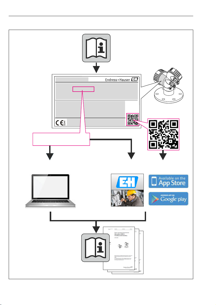
Detailed information about the device can be found in the
Operating Instructions and the other documentation:
• On the CD-ROM supplied (not included in the delivery for all
device versions).
• Available for all device versions via:
– Internet: www.endress.com/deviceviewer
– Smart phone/tablet: Endress+Hauser Operations App
Page 2
TAG No.: XXX000
Ser. No.: X000X000000
Order code 00X00-XXXX0XX0XXX
www.endress.com/deviceviewer Endress+Hauser Operations App
Serial number
Proline Promass F 100
2 Endress+Hauser
A0023555
Page 3

Proline Promass F 100 Table of contents
Table of contents
1 Document information ........................................................... 4
1.1 Symbols used ........................................................................ 4
2 Basic safety instructions ......................................................... 5
2.1 Requirements for the personnel ........................................................... 5
2.2 Designated use ....................................................................... 6
2.3 Workplace safety ...................................................................... 7
2.4 Operational safety ..................................................................... 7
2.5 Product safety ........................................................................ 7
2.6 IT security ........................................................................... 7
3 Product description .............................................................. 8
4 Incoming acceptance and product identification .................................. 8
4.1 Incoming acceptance ................................................................... 8
4.2 Product identification .................................................................. 9
5 Storage and transport ........................................................... 10
5.1 Storage conditions .................................................................... 10
5.2 Transporting the product ............................................................... 10
6 Installation ..................................................................... 12
6.1 Installation conditions ................................................................. 12
6.2 Mounting the measuring device .......................................................... 20
6.3 Post-installation check ................................................................. 23
7 Electrical connection ............................................................ 24
7.1 Connection conditions ................................................................. 24
7.2 Connecting the measuring device ......................................................... 37
7.3 Hardware settings .................................................................... 39
7.4 Ensuring the degree of protection ........................................................ 44
7.5 Post-connection check ................................................................. 44
8 Operation options .............................................................. 45
8.1 Structure and function of the operating menu ................................................ 45
8.2 Access to the operating menu via the Web browser ............................................ 45
8.3 Access to the operating menu via the operating tool ........................................... 49
9 System integration .............................................................. 49
9.1 Cyclic data transmission ............................................................... 49
10 Commissioning ................................................................. 54
10.1 Function check ...................................................................... 54
10.2 Establishing a connection via FieldCare .................................................... 54
10.3 Configuring the device address via software ................................................. 54
10.4 Configuring the measuring device ........................................................ 55
10.5 Protecting settings from unauthorized access ................................................ 55
11 Diagnostic information ......................................................... 56
Endress+Hauser 3
Page 4
Document information Proline Promass F 100
DANGER
WARNING
CAUTION
NOTICE
1 Document information
1.1 Symbols used
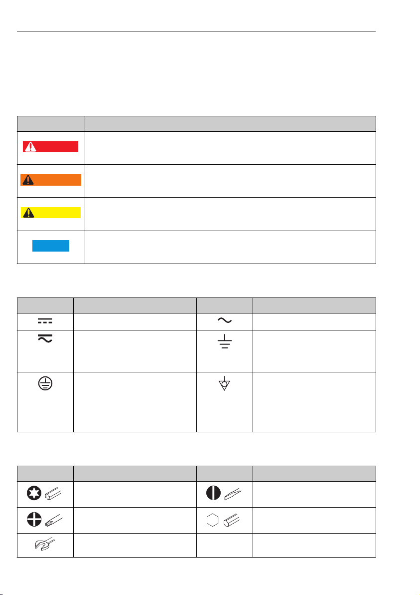
1.1.1 Safety symbols
Symbol Meaning
DANGER!
This symbol alerts you to a dangerous situation. Failure to avoid this situation will result in
serious or fatal injury.
WARNING!
This symbol alerts you to a dangerous situation. Failure to avoid this situation can result in
serious or fatal injury.
CAUTION!
This symbol alerts you to a dangerous situation. Failure to avoid this situation can result in
minor or medium injury.
NOTE!
This symbol contains information on procedures and other facts which do not result in personal
injury.
1.1.2 Electrical symbols
Symbol Meaning Symbol Meaning
Direct current Alternating current
Direct current and alternating current Ground connection
Protective ground connection
A terminal which must be connected to
ground prior to establishing any other
connections.
A grounded terminal which, as far as
the operator is concerned, is grounded
via a grounding system.
Equipotential connection
A connection that has to be connected
to the plant grounding system: This
may be a potential equalization line or
a star grounding system depending on
national or company codes of practice.
1.1.3 Tool symbols
Symbol Meaning Symbol Meaning
Torx screwdriver Flat blade screwdriver
Phillips head screwdriver Allen key
Open-ended wrench
4 Endress+Hauser
Page 5
Proline Promass F 100 Basic safety instructions
,…,
,…,
-
.
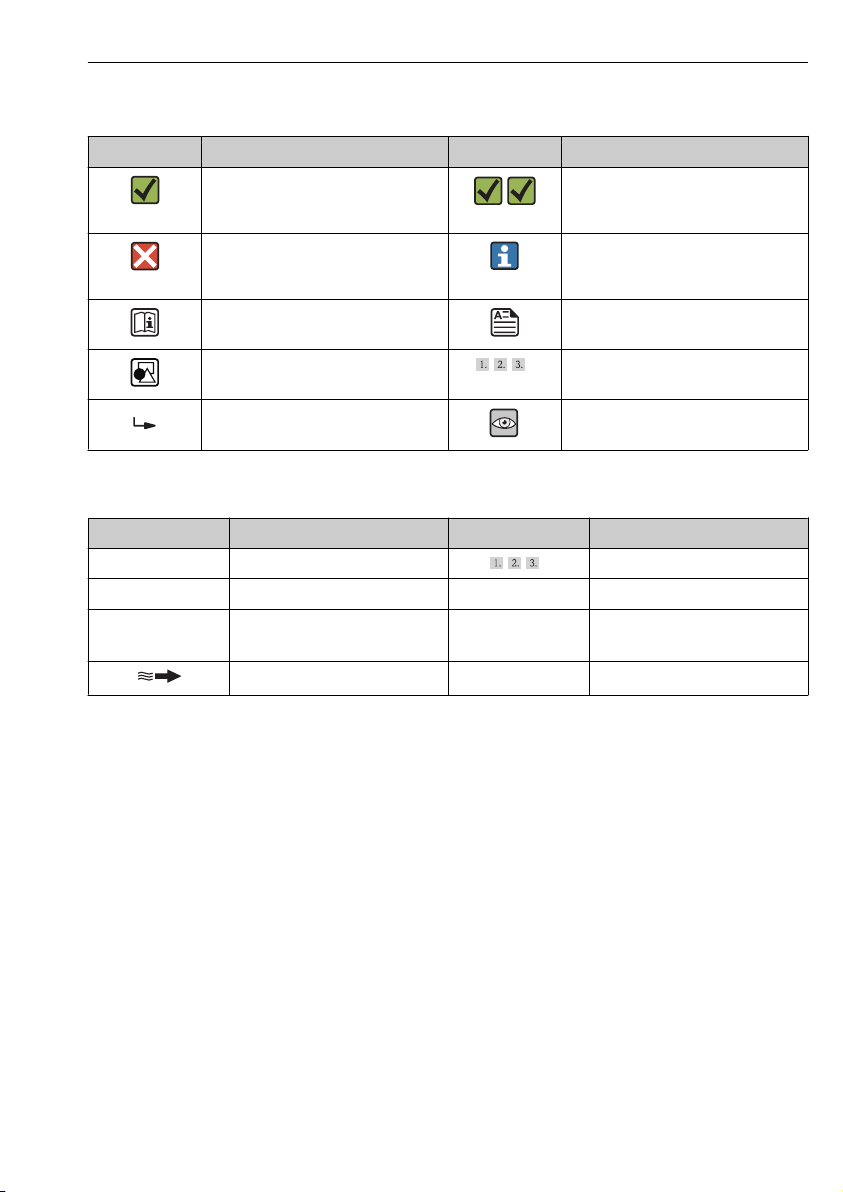
1.1.4 Symbols for certain types of information
Symbol Meaning Symbol Meaning
Permitted
Procedures, processes or actions that
are permitted.
Forbidden
Procedures, processes or actions that
are forbidden.
Reference to documentation Reference to page
Preferred
Procedures, processes or actions that
are preferred.
Tip
Indicates additional information.
Reference to graphic
Result of a sequence of actions Visual inspection
Series of steps
1.1.5 Symbols in graphics
Symbol Meaning Symbol Meaning
1, 2, 3,... Item numbers
A, B, C, ... Views A-A, B-B, C-C, ... Sections
Hazardous area
Flow direction
Series of steps
Safe area (non-hazardous area)
2 Basic safety instructions
2.1 Requirements for the personnel
The personnel must fulfill the following requirements for its tasks:
Trained, qualified specialists must have a relevant qualification for this specific function
‣
and task
Are authorized by the plant owner/operator
‣
Are familiar with federal/national regulations
‣
Before beginning work, the specialist staff must have read and understood the instructions
‣
in the Operating Instructions and supplementary documentation as well as in the
certificates (depending on the application)
Following instructions and basic conditions
‣
Endress+Hauser 5
Page 6

Basic safety instructions Proline Promass F 100
2.2 Designated use
Application and media
The measuring device described in these Instructions is intended only for flow measurement
of liquids and gases.
Depending on the version ordered, the measuring device can also measure potentially
explosive, flammable, poisonous and oxidizing media.
Measuring devices for use in hazardous areas, in hygienic applications or in applications
where there is an increased risk due to process pressure, are labeled accordingly on the
nameplate.
To ensure that the measuring device remains in proper condition for the operation time:
Only use the measuring device in full compliance with the data on the nameplate and the
‣
general conditions listed in the Operating Instructions and supplementary documentation.
Based on the nameplate, check whether the ordered device is permitted for the intended
‣
use in the hazardous area (e.g. explosion protection, pressure vessel safety).
Use the measuring device only for media against which the process-wetted materials are
‣
adequately resistant.
If the measuring device is not operated at atmospheric temperature, compliance with the
‣
relevant basic conditions specified in the associated device documentation is absolutely
essential.
Incorrect use
Non-designated use can compromise safety. The manufacturer is not liable for damage caused
by improper or non-designated use.
WARNING
L
Danger of breakage of the measuring tube due to corrosive or abrasive fluids.
Housing breakage due to mechanical overload possible!
Verify the compatibility of the process fluid with the measuring tube material.
‣
Ensure the resistance of all fluid-wetted materials in the process.
‣
Observe the specified pressure and temperature range.
‣
Verification for borderline cases:
For special fluids and fluids for cleaning, Endress+Hauser is glad to provide assistance in
‣
verifying the corrosion resistance of fluid-wetted materials, but does not accept any
warranty or liability as minute changes in the temperature, concentration or level of
contamination in the process can alter the corrosion resistance properties.
Residual risks
WARNING
L
Danger of housing breaking due to measuring tube breakage!
In the event of a measuring tube breakage for a device version without rupture disk it is
‣
possible for the pressure loading capacity of the sensor housing to be exceeded. This can
lead to rupture or failure of the sensor housing.
The external surface temperature of the housing can increase by max. 20 K due to the power
consumption of the electronic components. Hot process fluids passing through the measuring
6 Endress+Hauser
Page 7

Proline Promass F 100 Basic safety instructions
device will further increase the surface temperature of the housing. The surface of the sensor,
in particular, can reach temperatures which are close to the fluid temperature.
Possible burn hazard due to fluid temperatures!
For elevated fluid temperature, ensure protection against contact to prevent burns.
‣
2.3 Workplace safety
For work on and with the device:
Wear the required personal protective equipment according to federal/national
‣
regulations.
For welding work on the piping:
Do not ground the welding unit via the measuring device.
‣
If working on and with the device with wet hands:
It is recommended to wear gloves on account of the higher risk of electric shock.
‣
2.4 Operational safety
Risk of injury.
Operate the device in proper technical condition and fail-safe condition only.
‣
The operator is responsible for interference-free operation of the device.
‣
2.5 Product safety
This measuring device is designed in accordance with good engineering practice to meet stateof-the-art safety requirements, has been tested, and left the factory in a condition in which it
is safe to operate.
It meets general safety standards and legal requirements. It also complies with the EC
directives listed in the device-specific EC Declaration of Conformity. Endress+Hauser confirms
this by affixing the CE mark to the device.
2.6 IT security
We only provide a warranty if the device is installed and used as described in the Operating
Instructions. The device is equipped with security mechanisms to protect it against any
inadvertent changes to the device settings.
IT security measures in line with operators' security standards and designed to provide
additional protection for the device and device data transfer must be implemented by the
operators themselves.
Endress+Hauser 7
Page 8
Product description Proline Promass F 100
1
+
2
1
+
2
3 Product description
One device version is available: compact version - transmitter and sensor form a mechanical
unit.
For detailed information on the product description, see the Operating Instructions for
the device.
4 Incoming acceptance and product identification
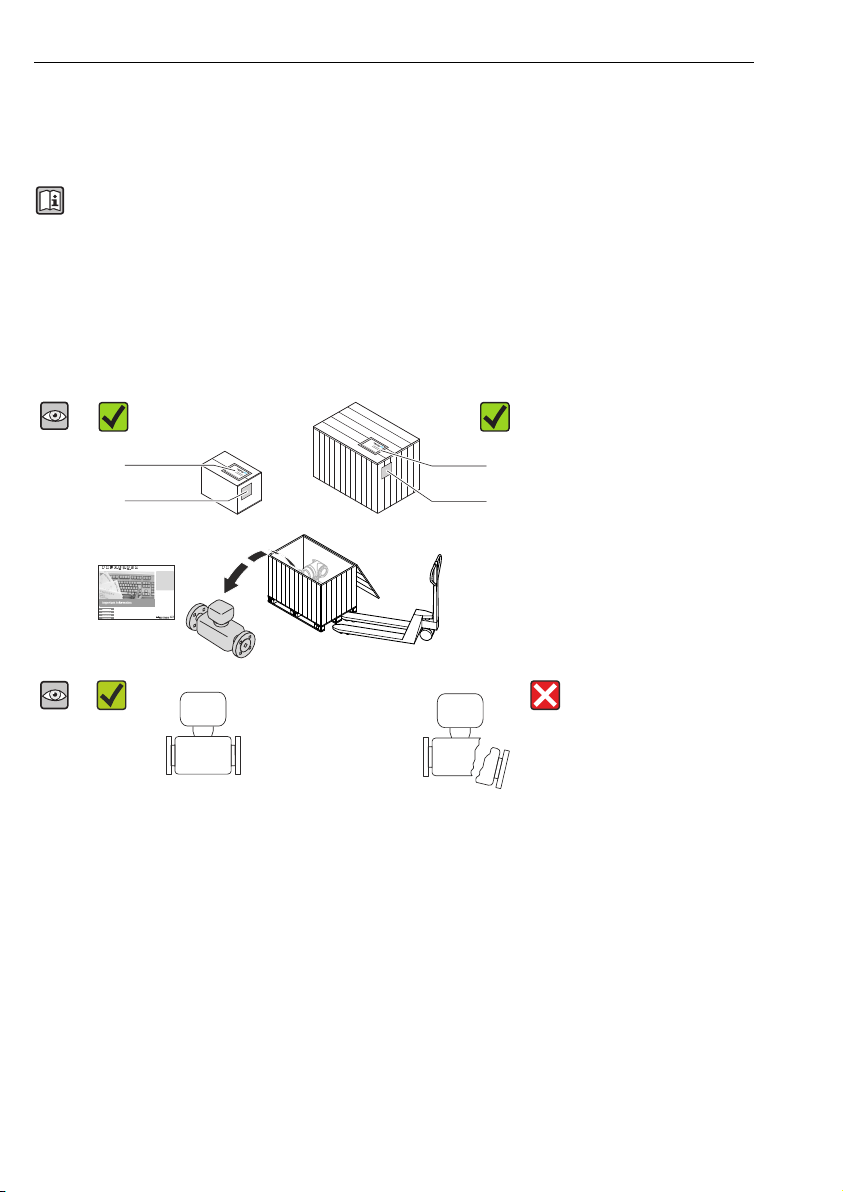
4.1 Incoming acceptance
Are the order codes on the
delivery note (1) and the
product sticker (2) identical?
Are the goods undamaged?
8 Endress+Hauser
Page 9
Proline Promass F 100 Incoming acceptance and product identification
Order code:
Ext. ord. cd.:
Ser. no.:
Order code:
Ext. ord. cd.:
Ser. no.:
1
2
3
4
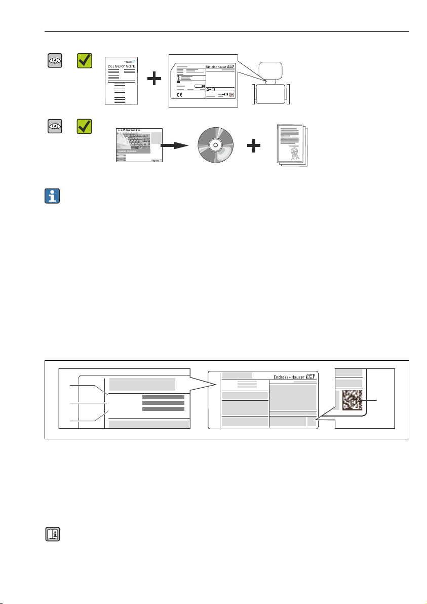
Do the nameplate data match
the ordering information on
the delivery note?
Is the CD-ROM with the
Technical Documentation
(depends on device version)
and documents present?
• If one of the conditions is not satisfied, contact your Endress+Hauser Sales Center.
• Depending on the device version, the CD-ROM might not be part of the delivery! The
Technical Documentation is available via the Internet or via the Endress+Hauser
Operations App.
4.2 Product identification
The following options are available for identification of the measuring device:
• Nameplate specifications
• Order code with breakdown of the device features on the delivery note
• Enter serial numbers from nameplates in W@M Device Viewer
(www.endress.com/deviceviewer): All information about the measuring device is displayed.
• Enter the serial number from the nameplates into the Endress+Hauser Operations App or
scan the 2-D matrix code (QR code) on the nameplate with the Endress+Hauser Operations
App: all the information for the measuring device is displayed.
A0021952
1 Example of a nameplate
1 Order code
2 Serial number (Ser. no.)
3 Extended order code (Ext. ord. cd.)
4 2-D matrix code (QR code)
For detailed information on the breakdown of the specifications on the nameplate, see
the Operating Instructions for the device .
Endress+Hauser 9
Page 10
Storage and transport Proline Promass F 100
5 Storage and transport
5.1 Storage conditions
Observe the following notes for storage:
• Store in original packaging.
• Do not remove protective covers or protective caps installed on process connections.
• Protect from direct sunlight.
• Storage temperature: –40 to +80 °C (–40 to +176 °F),
Order Code "Test, Certificate", Option JM: –50 to +60 °C (–58 to +140 °F),
• Store in a dry and dust-free place.
• Do not store outdoors.
5.2 Transporting the product
Transport the measuring device to the measuring point in the original packaging.
A0015604
Do not remove protective covers or caps installed on process connections. They prevent
mechanical damage to the sealing surfaces and contamination in the measuring tube.
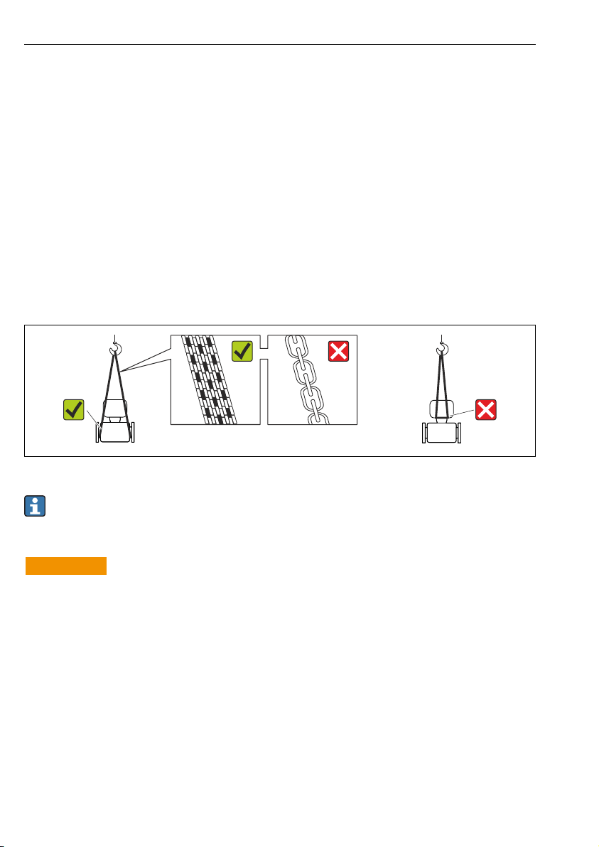
5.2.1 Measuring devices without lifting lugs
WARNING
L
Center of gravity of the measuring device is higher than the suspension points of the
webbing slings.
Risk of injury if the measuring device slips.
Secure the measuring device against slipping or turning.
‣
Observe the weight specified on the packaging (stick-on label).
‣
10 Endress+Hauser
Page 11

Proline Promass F 100 Storage and transport
A0015606
5.2.2 Measuring devices with lifting lugs
CAUTION
L
Special transportation instructions for devices with lifting lugs
Only use the lifting lugs fitted on the device or flanges to transport the device.
‣
The device must always be secured at two lifting lugs at least.
‣
5.2.3 Transporting with a fork lift
If transporting in wood crates, the floor structure enables the crates to be lifted lengthwise or
at both sides using a forklift.
Endress+Hauser 11
Page 12
Installation Proline Promass F 100
6 Installation
6.1 Installation conditions
No special measures such as supports are necessary. External forces are absorbed by the
construction of the device.
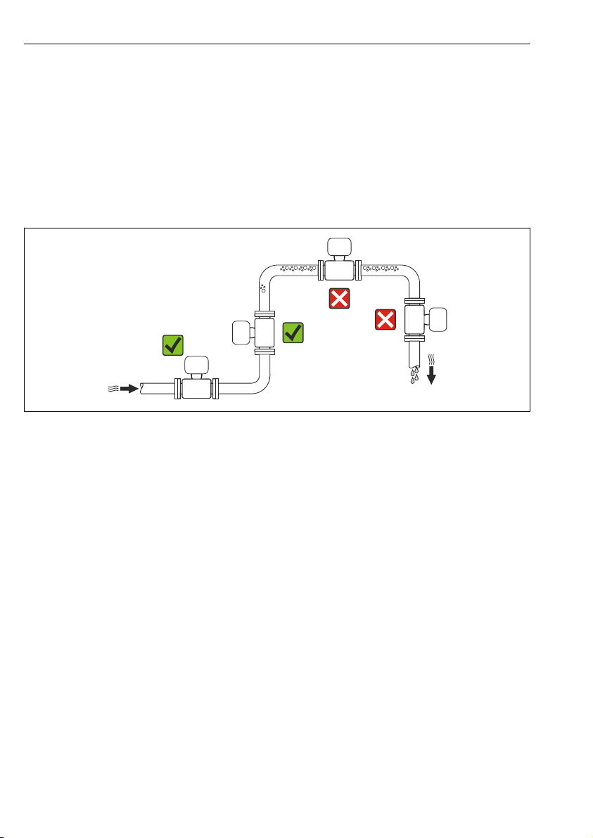
6.1.1 Mounting position
Mounting location
A0023344
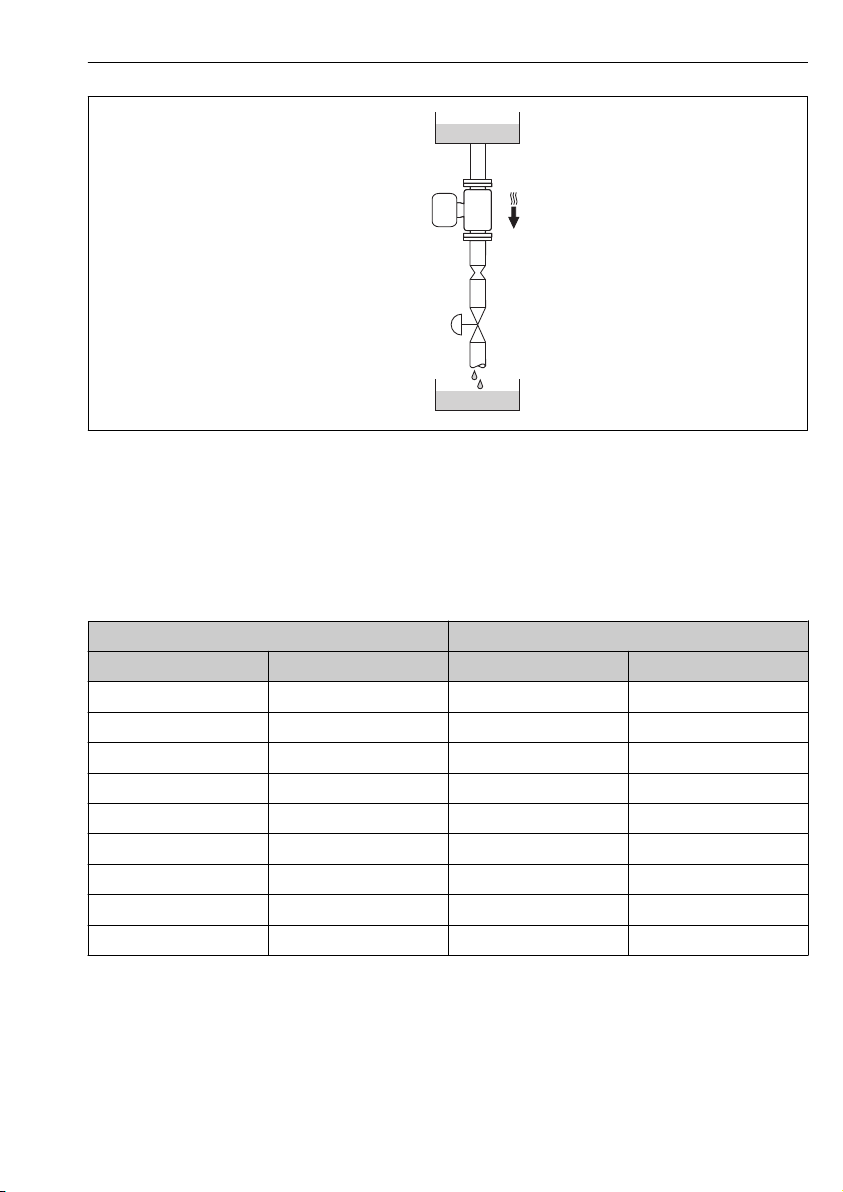
Installation in down pipes
However, the following installation suggestion allows for installation in an open vertical
pipeline. Pipe restrictions or the use of an orifice with a smaller cross-section than the
nominal diameter prevent the sensor running empty while measurement is in progress.
12 Endress+Hauser
Page 13
Proline Promass F 100 Installation
1
2
3
4
5
A0015596
2 Installation in a down pipe (e.g. for batching applications)
1 Supply tank
2 Sensor
3 Orifice plate, pipe restriction
4 Valve
5 Batching tank
DN Ø orifice plate, pipe restriction
[mm] [in] [mm] [in]
8 ³⁄₈ 6 0.24
15 ½ 10 0.40
25 1 14 0.55
40 1½ 22 0.87
50 2 28 1.10
80 3 50 1.97
100 4 65 2.60
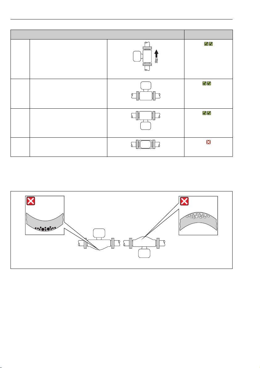
Orientation
150 6 90 3.54
250 10 150 5.91
The direction of the arrow on the sensor nameplate helps you to install the sensor according
to the flow direction.
Endress+Hauser 13
Page 14
Installation Proline Promass F 100
1 2
Orientation Recommendation
A Vertical orientation
A0015591
B Horizontal orientation, transmitter
head up
A0015589
C Horizontal orientation, transmitter
head down
A0015590
1)
Exception:
2)
Exception:
D Horizontal orientation, transmitter
head at side
A0015592
1) Applications with low process temperatures may reduce the ambient temperature. To maintain the minimum
ambient temperature for the transmitter, this orientation is recommended.
2) Applications with high process temperatures may increase the ambient temperature. To maintain the maximum
ambient temperature for the transmitter, this orientation is recommended.
A0014057
14 Endress+Hauser
Page 15
Proline Promass F 100 Installation
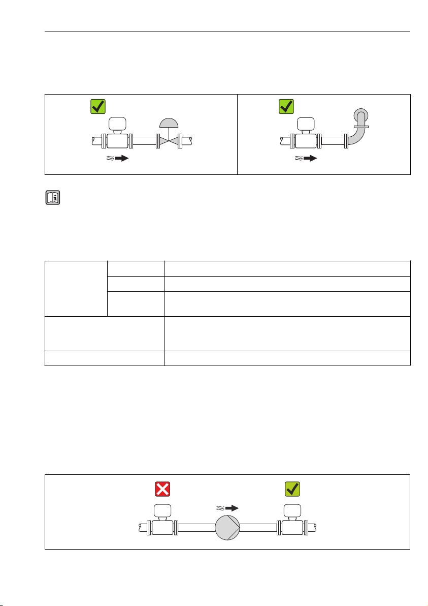
Inlet and outlet runs
No special precautions need to be taken for fittings which create turbulence, such as valves,
elbows or T-pieces, as long as no cavitation occurs → 15.
A0015597 A0015598
For the dimensions and installation lengths of the device, see the "Technical Information"
document, "Mechanical construction" section
6.1.2 Requirements from environment and process
Ambient temperature range
Measuring device Non-Ex –40 to +60 °C (–40 to +140 °F)
Ex na, NI version –40 to +60 °C (–40 to +140 °F)
Ex ia, IS version • –40 to +60 °C (–40 to +140 °F)
Local display –20 to +60 °C (–4 to +140 °F)
Safety Barrier Promass 100 –40 to +60 °C (–40 to +140 °F)
• –50 to +60 °C (–58 to +140 °F) (Order code for "Test, certificate", option JM)
The readability of the display may be impaired at temperatures outside the
temperature range.
If operating outdoors:
‣
Avoid direct sunlight, particularly in warm climatic regions.
System pressure
For this reason, the following mounting locations are recommended:
• At the lowest point in a vertical pipe
• Downstream from pumps (no danger of vacuum)
A0015594
Endress+Hauser 15
Page 16
Installation Proline Promass F 100
t
a
0
10
30
20
40
[mm][in]
80 90 100 110
[°C]
[°F]
200 250 290
0.5
1.0
1.5
0
T
40(104)
T
60(140)
t
120 130 140
T
m
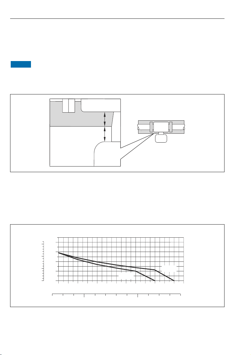
Thermal insulation
In the case of some fluids, it is important that the heat radiated from the sensor to the
transmitter is kept to a minimum. A wide range of materials can be used for the required
insulation.
NOTICE
Electronics overheating on account of thermal insulation!
Observe maximum permitted insulation height of the transmitter neck so that the
‣
transmitter head is completely free.
A0019919
a Minimum distance to insulation
t maximum Insulation thickness
The minimum distance between the transmitter housing and the insulation is
10 mm (0.39 in) so that the transmitter head remains completely exposed.
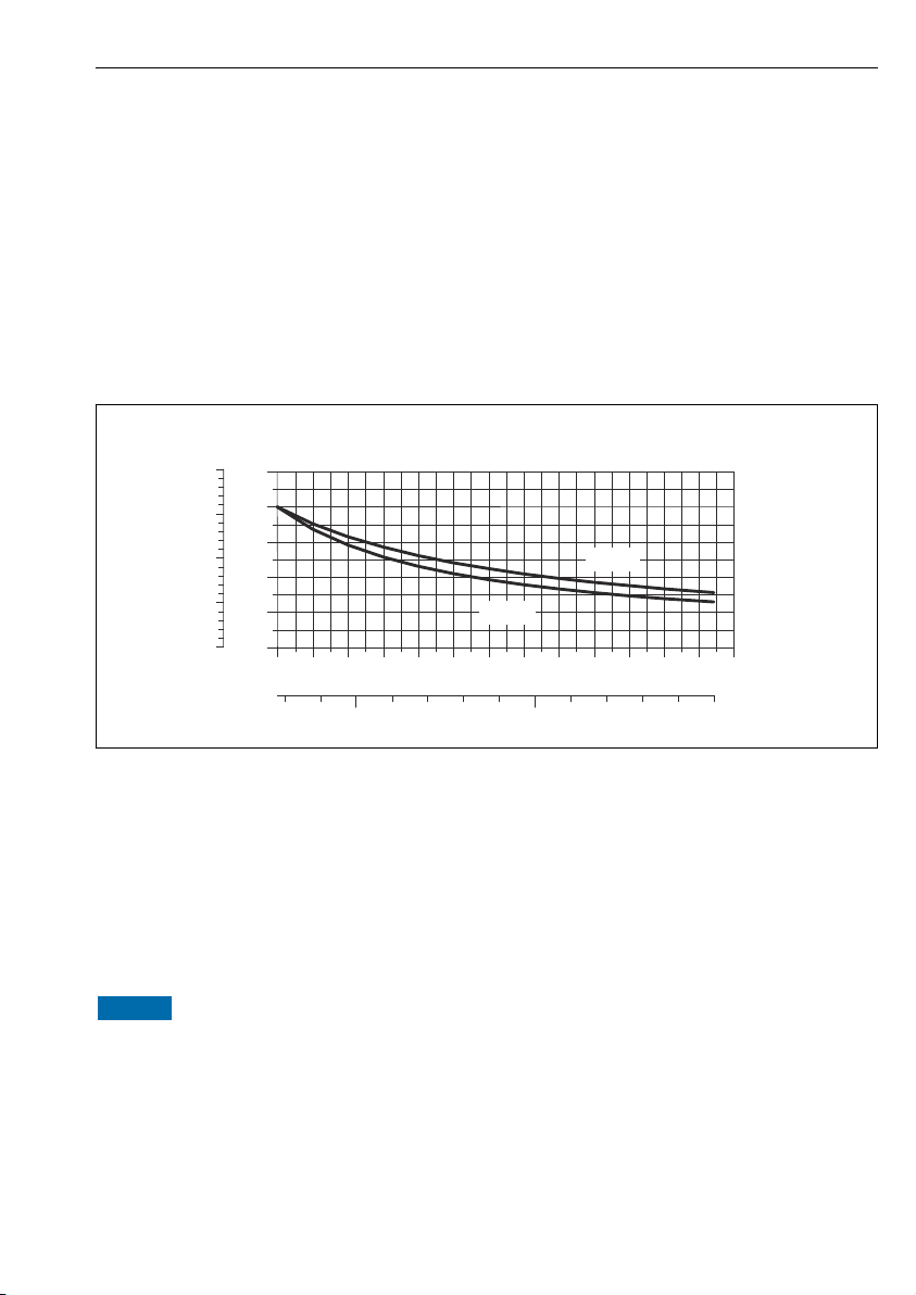
Maximum recommended insulation thickness
3 Maximum recommended insulation thickness depending on the temperature of the medium and
the ambient temperature
16 Endress+Hauser
A0023173
Page 17
Proline Promass F 100 Installation
0
20
60
40
80
[in]
1
2
3
0
t
100
4
[mm]
T
40(104)
T
60(140)
80 100 120 140
200 300 400
160 180 200
[°F]
T
m
[°C]
t Insulation thickness
T
m
T
40(104)
T
60(140)
Medium temperature
Maximum recommended insulation thickness at an ambient temperature of Ta = 40 °C (104 °F)
Maximum recommended insulation thickness at an ambient temperature of Ta = 60 °C (140 °F)
Maximum recommended insulation thickness for the extended temperature range and
insulation
For the extended temperature range, version with long extension neck, order code for
"Measuring tube material", option SD, SE, SF, TH or extension neck for insulation, order code
for "Sensor option", option CG:
4 Maximum recommended insulation thickness depending on the temperature of the medium and
the ambient temperature
t Insulation thickness
T
m
T
40(104)
T
60(140)
NOTICE
Danger of overheating with insulation
Ensure that the temperature at the lower end of the transmitter housing does not exceed
‣
80 °C (176 °F)
Medium temperature
Maximum recommended insulation thickness at an ambient temperature of Ta = 40 °C (104 °F)
Maximum recommended insulation thickness at an ambient temperature of Ta = 60 °C (140 °F)
Endress+Hauser 17
A0023177
Page 18

Installation Proline Promass F 100
NOTICE
The insulation can also be thicker than the maximum recommended insulation
thickness.
Prerequisite:
Ensure that convection takes place on a sufficiently large scale at the transmitter neck.
‣
Ensure that a sufficiently large area of the housing support remains exposed. The
‣
uncovered part serves as a radiator and protects the electronics from overheating and
excessive cooling.
Heating
NOTICE
Electronics can overheat due to elevated ambient temperature!
Observe maximum permitted ambient temperature for the transmitter → 15.
‣
Depending on the fluid temperature, take the device orientation requirements into
‣
account .
NOTICE
Danger of overheating when heating
Ensure that the temperature at the lower end of the transmitter housing does not exceed
‣
80 °C (176 °F)
Ensure that convection takes place on a sufficiently large scale at the transmitter neck.
‣
Ensure that a sufficiently large area of the housing support remains exposed. The
‣
uncovered part serves as a radiator and protects the electronics from overheating and
excessive cooling.
Heating options
If a fluid requires that no heat loss should occur at the sensor, users can avail of the following
heating options:
• Electrical heating, e.g. with electric band heaters
• Via pipes carrying hot water or steam
• Via heating jackets
For detailed information about heating with electrical band heaters, refer to the
Operating Instructions for the device on the CD-ROM provided
Vibrations
The high oscillation frequency of the measuring tubes ensures that the correct operation of
the measuring system is not influenced by plant vibrations.
6.1.3 Special mounting instructions
Rupture disk
Make sure that the function and operation of the rupture disk is not impeded through the
installation of the device. The position of the rupture disk is indicated on a sticker beside it.
For additional information that is relevant to the process .
The existing connecting nozzles are not intended for the purpose of rinsing or pressure
monitoring, but instead serve as the mounting location for the rupture disk.
18 Endress+Hauser
Page 19

Proline Promass F 100 Installation
E
D
45°
RUPTURE DISK
i
2
3
1
B
C
A
However, by means of the connection available on the rupture disk holder, the escaping fluid
(in case of a disk rupture) can be collected by connecting a suitable relief system.
A0008361
1 Rupture disk label
2 Rupture disk with 1/2" NPT internal thread with 1" width across flat
3 Transport protection
DN A B C D E
[mm] [in] [mm] [in] [in] [in] [mm] [in] [mm] [in]
8 ³⁄₈ Approx.42 Approx.1.65 AF 1 ½ NPT 62 2.44 216 8.50
15 ½ Approx.42 Approx.1.65 AF 1 ½ NPT 62 2.44 220 8.66
25 1 Approx.42 Approx.1.65 AF 1 ½ NPT 62 2.44 260 10.24
40 1½ Approx.42 Approx.1.65 AF 1 ½ NPT 67 2.64 310 12.20
50 2 Approx.42 Approx.1.65 AF 1 ½ NPT 79 3.11 452 17.78
80 3 Approx.42 Approx.1.65 AF 1 ½ NPT 101 3.98 560 22.0
100 4 Approx.42 Approx.1.65 AF 1 ½ NPT 120 4.72 684 27.0
150 6 Approx.42 Approx.1.65 AF 1 ½ NPT 141 5.55 880 34.6
Endress+Hauser 19
Page 20

Installation Proline Promass F 100
D
E
RUPTURE DISK
i
1
B
C
A
3
2
A0009733
1 Rupture disk label
2 Rupture disk with 1/2" NPT internal thread with 1" width across flat
3 Transport protection
DN A B C D E
[mm] [in] [mm] [in] [in] [in] [mm] [in] [mm] [in]
250 10 Approx. 42 Approx. 1.65 AF 1 ½ NPT 182 7.17 380 14.96
For detailed information about using a rupture disk, refer to the Operating Instructions
for the device on the CD-ROM provided
Zero point adjustment
All measuring devices are calibrated in accordance with state-of-the-art technology.
Calibration takes place under reference conditions . Therefore, a zero point adjustment in the
field is generally not required.
Experience shows that zero point adjustment is advisable only in special cases:
• To achieve maximum measuring accuracy even with low flow rates
• Under extreme process or operating conditions (e.g. very high process temperatures or very
high-viscosity fluids).
6.2 Mounting the measuring device
6.2.1 Required tools
For sensor
For flanges and other process connections: Corresponding mounting tools
20 Endress+Hauser
Page 21

Proline Promass F 100 Installation
6.2.2 Preparing the measuring device
1. Remove all remaining transport packaging.
2. Remove any protective covers or protective caps present from the sensor.
3. Remove stick-on label on the electronics compartment cover.
6.2.3 Mounting the measuring device
WARNING
L
Danger due to improper process sealing!
Ensure that the inside diameters of the gaskets are greater than or equal to that of the
‣
process connections and piping.
Ensure that the gaskets are clean and undamaged.
‣
Install the gaskets correctly.
‣
1. Ensure that the direction of the arrow on the nameplate of the sensor matches the flow
direction of the fluid.
2. Install the measuring device or turn the transmitter housing so that the cable entries do
not point upwards.
A0013964
6.2.4 Turning the display module
The local display is only available with the following device version:
Order code for "Display; Operation", option B: 4-line; lit, via communication
The display module can be turned to optimize display readability.
Endress+Hauser 21
Page 22

Installation Proline Promass F 100
1.
2.
3.
4.
5.
6.
7.
4.
4.
3 mm
1.
2.
3.
4.
5.
6.
3.
3. 3.
8 mm
Aluminum housing version, AlSi10Mg, coated
A0023192
Compact and ultra-compact housing version, hygienic, stainless
22 Endress+Hauser
A0023195
Page 23

Proline Promass F 100 Installation
6.3 Post-installation check
Is the device undamaged (visual inspection)?
Does the measuring device conform to the measuring point specifications?
For example:
• Process temperature
• Process pressure (refer to the chapter on "Pressure-temperature ratings" of the "Technical Information"
document on the CD-ROM provided)
• Ambient temperature → 15
• Measuring range
Has the correct orientation for the sensor been selected ?
• According to sensor type
• According to medium temperature
• According to medium properties (outgassing, with entrained solids)
Does the arrow on the sensor nameplate match the direction of flow of the fluid through the piping
→ 13?
Are the measuring point identification and labeling correct (visual inspection)?
Is the device adequately protected from precipitation and direct sunlight?
Are the securing screw and securing clamp tightened securely?
Endress+Hauser 23
Page 24

Electrical connection Proline Promass F 100
7 Electrical connection
The measuring device does not have an internal circuit breaker. For this reason, assign
the measuring device a switch or power-circuit breaker so that the power supply line can
be easily disconnected from the mains.
7.1 Connection conditions
7.1.1 Required tools
• For cable entries: Use corresponding tools
• For securing clamp (on aluminum housing): Allen screw3 mm
• For securing screw (for stainless steel housing): open-ended wrench 8 mm
• Wire stripper
• When using stranded cables: crimping tool for ferrule
7.1.2 Requirements for connecting cable
The connecting cables provided by the customer must fulfill the following requirements.
Electrical safety
In accordance with applicable federal/national regulations.
Permitted temperature range
• –40 °C (–40 °F) to +80 °C (+176 °F)
• Minimum requirement: cable temperature range ≥ ambient temperature +20 K
Power supply cable
Standard installation cable is sufficient.
Signal cable
Current output
For 4-20 mA HART: Shielded cable recommended. Observe grounding concept of the plant.
Pulse/frequency/switch output
Standard installation cable is sufficient.
FOUNDATION Fieldbus
Twisted, shielded two-wire cable.
For further information on planning and installing FOUNDATION Fieldbus networks see:
• Operating Instructions for "FOUNDATION Fieldbus Overview" (BA00013S)
• FOUNDATION Fieldbus Guideline
• IEC 61158-2 (MBP)
24 Endress+Hauser
Page 25

Proline Promass F 100 Electrical connection
PROFIBUS PA
Twisted, shielded two-wire cable. Cable type A is recommended.
For further information on planning and installing PROFIBUS PA networks see:
• Operating Instructions "PROFIBUS DP/PA: Guidelines for planning and commissioning"
(BA00034S)
• PNO Directive 2.092 "PROFIBUS PA User and Installation Guideline"
• IEC 61158-2 (MBP)
PROFIBUS DP
The IEC 61158 standard specifies two types of cable (A and B) for the bus line which can be
used for every transmission rate. Cable type A is recommended.
For detailed information about the specification of the connecting cable, see the
Operating Instructions for the device.
Modbus RS485
The EIA/TIA-485 standard specifies two types of cable (A and B) for the bus line which can be
used for every transmission rate. Cable type A is recommended.
For detailed information about the specification of the connecting cable, see the
Operating Instructions for the device.
EtherNet/IP
The standard ANSI/TIA/EIA-568-B.2 Annex specifies CAT 5 as the minimum category for a
cable used for EtherNet/IP. CAT 5e and CAT 6 are recommended.
For more information on planning and installing EtherNet/IP networks, please refer to
the "Media Planning and Installation Manual. EtherNet/IP" of ODVA Organization.
Connecting cable between Safety Barrier Promass 100 and measuring device
Cable type Shielded twisted-pair cable with 2x2 wires. When grounding the cable shield, observe
Maximum cable resistance 2.5 Ω, one side
the grounding concept of the plant.
Comply with the maximum cable resistance specifications to ensure the operational
reliability of the measuring device.
Wire cross-section Maximum cable length
[mm2] [AWG] [m] [ft]
0.5 20 70 230
0.75 18 100 328
1.0 17 100 328
1.5 16 200 656
2.5 14 300 984
Endress+Hauser 25
Page 26

Electrical connection Proline Promass F 100
Cable diameter
• Cable glands supplied:
M20 × 1.5 with cable 6 to 12 mm (0.24 to 0.47 in)
• Spring terminals:
Wire cross-sections 0.5 to 2.5 mm2 (20 to 14 AWG)
• With Safety Barrier Promass 100:
Plug-in screw terminals for wire cross-sections 0.5 to 2.5 mm2 (20 to 14 AWG)
26 Endress+Hauser
Page 27

Proline Promass F 100 Electrical connection
L
L
26
27
+
_
24
25
1
2
+
_
+
_
1
2
3
7.1.3 Terminal assignment
Transmitter
Connection version 4-20 mA HART with pulse/frequency/switch output
Order code for "Output", option B
Depending on the housing version, the transmitters can be ordered with terminals or device
plugs.
A0016888
5 Terminal assignment 4-20 mA HART with pulse/frequency/switch output
1 Power supply: DC 24 V
2 Output 1: 4-20 mA HART (active)
3 Output 2: pulse/frequency/switch output (passive)
Terminal number
Order code for
"Output"
Option B DC 24 V 4-20 mA HART (active) Pulse/frequency/switch
Order code for "Output":
Option B: 4-20 mA HART with pulse/frequency/switch output
Endress+Hauser 27
Power supply Output 1 Output 2
2 (L-) 1 (L+) 27 (–) 26 (+) 25 (–) 24 (+)
output (passive)
Page 28

Electrical connection Proline Promass F 100
L
L
26
27BA
1
2
+
_
1
2
PROFIBUS DP connection version
For use in the non-hazardous area and Zone 2/Div. 2.
Order code for "Output", option L
Depending on the housing version, the transmitters can be ordered with terminals or device
plugs.
A0022716
6 PROFIBUS DP terminal assignment
1 Power supply: DC 24 V
2 PROFIBUS DP
Terminal number
Order code for
"Output"
Option L DC 24 V B A
Order code for "Output":
Option L: PROFIBUS DP, for use in non-hazardous areas and Zone 2/div. 2
28 Endress+Hauser
Power supply Output
2 (L-) 1 (L+) 26 (RxD/TxD-P) 27 (RxD/TxD-N)
Page 29

Proline Promass F 100 Electrical connection
L
L
26
27AB
1
2
+
_
1
2
Modbus RS485 connection version
For use in the non-hazardous area and Zone 2/Div. 2.
Order code for "Output", option M
Depending on the housing version, the transmitters can be ordered with terminals or device
plugs.
A0019528
7 Modbus RS485 terminal assignment, connection version for use in non-hazardous areas and Zone
2/Div. 2
1 Power supply: DC 24 V
2 Modbus RS485
Terminal number
Order code for
"Output"
Option M DC 24 V Modbus RS485
Order code for "Output":
Option M Modbus RS485, for use in non-hazardous areas and Zone 2/Div. 2
Endress+Hauser 29
Power supply Output
2 (L-) 1 (L+) 27 (B) 26 (A)
Page 30

Electrical connection Proline Promass F 100
L
L
62
72AB
10
20
+
_
1
2
Modbus RS485 connection version
For use in the intrinsically safe area. Connection via Safety Barrier Promass 100.
Order code for "Output", option M
Depending on the housing version, the transmitters can be ordered with terminals or device
plugs.
A0017053
8 Modbus RS485 terminal assignment, connection version for use in intrinsically safe areas
(connection via Safety Barrier Promass 100)
1 Intrinsically safe power supply
2 Modbus RS485
Order code for
"Output"
Option M Intrinsically safe supply voltage Modbus RS485 intrinsically safe
Order code for "Output":
Option M: Modbus RS485, for use in intrinsically safe areas (connection via Safety Barrier Promass 100)
30 Endress+Hauser
20 (L-) 10 (L+) 72 (B) 62 (A)
Page 31

Proline Promass F 100 Electrical connection
L
L
1
2
+
_
1
2
EtherNet/IP connection version
Order code for "Output", option N
Depending on the housing version, the transmitters can be ordered with terminals or device
plugs.
A0017054
9 EtherNet/IP terminal assignment
1 Power supply: DC 24 V
2 EtherNet/IP
Terminal number
Order code for
"Output"
Option N DC 24 V EtherNet/IP
Order code for "Output":
Option N: EtherNet/IP
Power supply Output
2 (L-) 1 (L+) Device plug M12x1
Endress+Hauser 31
Page 32

Electrical connection Proline Promass F 100
A
Safe area
1
L+2L
27
26
A B
Power
supply
24V
DC
Modbus
RS485
10207262
L+L A B
Power
supply
Modbus
RS485
Hazardous area
Safety Barrier
Promass 100
Power
Communication
Lift panel for
bus termination
1
2
A
Safety Barrier Promass 100
A0016922
10 Safety Barrier Promass 100 with terminals
1 Non-hazardous area and Zone 2/Div. 2
2 Intrinsically safe area
32 Endress+Hauser
Page 33

Proline Promass F 100 Electrical connection
1
2
4
3
5
3
2
4
1
5
3
2
4
1
5
7.1.4 Pin assignment, device plug
Supply voltage
For all connection versions except MODBUS RS485 intrinsically safe (device side)
Device plug MODBUS RS485 intrinsically safe with supply voltage → 34
Pin Assignment
1 L+ DC 24 V
2
3
4 L- DC 24 V
5 Grounding/shielding
Coding Plug/socket
A0016809
A Plug
4-20 mA HART with pulse/frequency/switch output
Device plug for signal transmission (device side)
Pin Assignment
1 + 4-20 mA HART (active)
2 - 4-20 mA HART (active)
3 + Pulse/frequency/switch output (passive)
4 - Pulse/frequency/switch output (passive)
5 Grounding/shielding
Coding Plug/socket
A0016810
A Socket
PROFIBUS DP
For use in the non-hazardous area and Zone 2/Div. 2.
Device plug for signal transmission (device side)
Pin Assignment
1
2 A PROFIBUS DP
3
4 B PROFIBUS DP
5 Grounding/shielding
Coding Plug/socket
Endress+Hauser 33
A0016811
B Socket
Page 34

Electrical connection Proline Promass F 100
1
2
4
3
5
3
2
4
1
5
3
2
4
1
MODBUS RS485
Device plug for signal transmission with supply voltage (device side), MODBUS RS485
(intrinsically safe)
Pin Assignment
1 L+ Supply voltage, intrinsically safe
2 A
3 B
4 L- Supply voltage, intrinsically safe
5 Grounding/shielding
Coding Plug/socket
A Plug
A0016809
Modbus RS485 intrinsically safe
Device plug for signal transmission (device side), MODBUS RS485 (not intrinsically safe)
For use in the non-hazardous area and Zone 2/Div. 2.
Pin Assignment
1
2 A Modbus RS485
3
4 B Modbus RS485
5 Grounding/shielding
Coding Plug/socket
A0016811
B Socket
EtherNet/IP
Device plug for signal transmission (device side)
Pin Assignment
1 + Tx
2 + Rx
3 - Tx
4 - Rx
Coding Plug/socket
D Socket
A0016812
7.1.5 Shielding and grounding
Modbus
The shielding and grounding concept requires compliance with the following:
• Electromagnetic compatibility (EMC)
• Explosion protection
• Personal protection equipment
34 Endress+Hauser
Page 35

Proline Promass F 100 Electrical connection
• National installation regulations and guidelines
• Observe cable specification → 24.
• Keep the stripped and twisted lengths of cable shield to the ground terminal as short as
possible.
• Seamless cable shielding.
Grounding of the cable shield
To comply with EMC requirements:
• Ensure the cable shield is grounded to the potential matching line at multiple points.
• Connect every local ground terminal to the potential matching line.
NOTICE
In systems without potential matching, the multiple grounding of the cable shield causes
mains frequency equalizing currents!
Damage to the bus cable shield.
Only ground the bus cable shield to either the local ground or the protective ground at one
‣
end.
PROFIBUS DP
Optimum electromagnetic compatibility (EMC) of the fieldbus system can only be guaranteed
if the system components and, in particular, the lines are shielded and the shield forms as
complete a cover as possible. A shield coverage of 90% is ideal.
• To ensure an optimum EMC protective effect, connect the shield as often as possible to the
reference ground.
• For reasons of explosion protection, you should refrain from grounding however.
To comply with both requirements, the fieldbus system allows three different types of
shielding:
• Shielding at both ends.
• Shielding at one end on the feed side with capacitance termination at the field device.
• Shielding at one end on the feed side.
Experience shows that the best results with regard to EMC are achieved in most cases in
installations with one-sided shielding on the feed side (without capacitance termination at
the field device). Appropriate measures with regard to input wiring must be taken to allow
unrestricted operation when EMC interference is present. These measures have been taken
into account for this device. Operation in the event of disturbance variables as per NAMUR
NE21 is thus guaranteed.
Where applicable, national installation regulations and guidelines must be observed during
the installation!
Where there are large differences in potential between the individual grounding points, only
one point of the shielding is connected directly with the reference ground. In systems without
potential equalization, therefore, cable shielding of fieldbus systems should only be grounded
on one side, for example at the fieldbus supply unit or at safety barriers.
Endress+Hauser 35
Page 36

Electrical connection Proline Promass F 100
21 3
+
-
+
-
+
-
4
5
5
78
6
6
6
6
6
6
.
-
NOTICE
In systems without potential matching, the multiple grounding of the cable shield causes
mains frequency equalizing currents!
Damage to the bus cable shield.
Only ground the bus cable shield to either the local ground or the protective ground at one
‣
end. Insulate the shield that is not connected.
A0019004
1 Controller (e.g. PLC)
2 Segment coupler PROFIBUS DP/PA
3 Cable shield
4 T-box
5 Measuring device
6 Local grounding
7 Bus terminator
8 Potential matching line
7.1.6 Preparing the measuring device
1. Remove dummy plug if present.
36 Endress+Hauser
Page 37

Proline Promass F 100 Electrical connection
1 2 1 2 3 4
A B C
2.
NOTICE
Insufficient sealing of the housing!
Operational reliability of the measuring device could be compromised.
Use suitable cable glands corresponding to the degree of protection.
‣
If measuring device is delivered without cable glands:
Provide suitable cable gland for corresponding connecting cable → 24.
3. If measuring device is delivered with cable glands:
Observe cable specification → 24.
7.2 Connecting the measuring device
NOTICE
Limitation of electrical safety due to incorrect connection!
For use in potentially explosive atmospheres, observe the information in the device-specific
‣
Ex documentation.
7.2.1 Connecting the transmitter
The connection of the transmitter depends on the following order codes:
• Housing version: compact or ultra-compact
• Connection version: device plug or terminals
11 Housing versions and connection versions
A Housing version: compact, aluminum coated
B Housing version: compact hygienic, stainless
1 Cable entry or device plug for signal transmission
2 Cable entry or device plug for supply voltage
C Housing version: ultra-compact, hygienic, stainless:
3 Device plug for signal transmission
4 Device plug for supply voltage
Endress+Hauser 37
A0016924
Page 38

Electrical connection Proline Promass F 100
10 (0.4)
mm (in)
1 2
3
2
1
2
1
2
3
8 mm
3 mm
8 mm
12 Device versions with connection examples
1 Cable
2 Device plug for signal transmission
3 Device plug for supply voltage
Depending on the housing version disconnect the local display from the main electronics
module: Operating Instructions for the device .
Connect the cable in accordance with the terminal assignment or the device plug pin
‣
assignment .
7.2.2 Connecting the Safety Barrier Promass 100
In the case of the device version with Modbus RS485 intrinsically safe, the transmitter must
be connected to the Safety Barrier Promass 100.
38 Endress+Hauser
A0017844
Page 39

Proline Promass F 100 Electrical connection
21
A
B
A
B
3
L+
L-
A
B
L+
L-
L- L+
A
B
5 6 7
8
4
A0016804
13 Electrical connection between the transmitter and Safety Barrier Promass 100
1 Control system (e.g. PLC)
2 Observe cable specification
3 Safety Barrier Promass 100: terminal assignment
4 Observe cable specification → 25
5 Non-hazardous area
6 Non-hazardous area and Zone 2/Div. 2
7 Intrinsically safe area
8 Transmitter: terminal assignment
7.2.3 Ensuring potential equalization
Requirements
No special measures for potential equalization are required.
For devices intended for use in hazardous locations, please observe the guidelines in the
Ex documentation (XA).
7.3 Hardware settings
7.3.1 Setting the device address
EtherNet/IP
The IP address of the measuring device can be configured for the network via DIP switches.
Addressing data
1st octet 2nd octet 3rd octet 4th octet
192. 168. 1. XXX
Endress+Hauser 39
IP address and configuration options
Page 40

Electrical connection Proline Promass F 100
OFF ON
1
2
3
4
5
6
7
8
9
10
1
2
4
8
16
32
64
128
- Write protection
- Default Ethernet
network settings
IP 192.168.1.212
IP Address setting
(last octet)
↓ ↓
Can only be configured via software addressing Can be configured via
software addressing
and hardware
addressing
IP address range 1 to 254 (4th octet)
IP address broadcast 255
Addressing mode ex works Software addressing; all DIP switches for hardware addressing are set to OFF.
IP address ex works DHCP server active
For device addressing via software → 54
Setting the address
A0017913
Set the desired IP address using the corresponding DIP switches on the I/O electronics
‣
module.
Hardware addressing with the configured IP address is enabled after 10 s.
PROFIBUS DP
The address must always be configured for a PROFIBUS DP/PA device. The valid address
range is between 1 and 126. In a PROFIBUS DP/PA network, each address can only be
assigned once. If an address is not configured correctly, the device is not recognized by the
master. All measuring devices are delivered from the factory with the device address 126 and
with the software addressing method.
40 Endress+Hauser
Page 41

Proline Promass F 100 Electrical connection
OFF ON
1
2
3
4
5
6
7
8
9
10
1
2
4
8
16
32
64
- Write protection
- Not used
PROFIBUS
address
- Software addressing
Setting the address
A0021265
14 Addressing using DIP switches on the I/O electronics module
1. Disable software addressing via DIP switch 8 (OFF).
2. Set the desired device address via the corresponding DIP switches.
Example → 14, 41: 1 + 16 + 32 = device address 49
The device demands rebooting after 10 s. After rebooting, hardware addressing is
enabled with the configured IP address.
7.3.2 Enabling the terminating resistor
PROFIBUS DP
To avoid incorrect communication transmission caused by impedance mismatch, terminate
the PROFIBUS DP cable correctly at the start and end of the bus segment.
• If the device is operated with a baud rate of 1.5 MBaud and under:
For the last transmitter on the bus, terminate via DIP switch 2 (bus termination) and DIP
switch 1 and 3 (bus polarization). Setting: ON – ON – ON → 15, 42.
• For baud rates > 1.5 MBaud:
Due to the capacitance load of the user and the line reflections generated as a result, ensure
that an external bus terminator is used.
It is generally advisable to use an external bus terminator as the entire segment can fail
if a device that is terminated internally is defective.
Endress+Hauser 41
Page 42

Electrical connection Proline Promass F 100
390 Ω
DIP 1
5V
26
27
220 Ω
DIP 2
0V
390 Ω
DIP 3
OFF ON
1
2
3
4
Bus polarisation
Bus termination
Bus polarisation
Not used
4.
1.
2.
3.
15 Termination using DIP switches on the I/O electronics module (for baud rates < 1.5 MBaud)
Modbus RS485
To avoid incorrect communication transmission caused by impedance mismatch, terminate
the Modbus RS485 cable correctly at the start and end of the bus segment.
42 Endress+Hauser
A0021274
Page 43

Proline Promass F 100 Electrical connection
2 - Not used
1 - Write protection
4 - Bus termination
3 - Not used
OFFON
26
27AB
220 W
26
27AB
220 W
ON
1 2
A
A
If the transmitter is used in the non-hazardous area or Zone 2/Div. 2
A0017610
16 Terminating resistor can be enabled via DIP switch on the main electronics module
If the transmitter is used in the intrinsically safe area
17 Terminating resistor can be enabled via DIP switch in the Safety Barrier Promass 100
A0017791
Endress+Hauser 43
Page 44

Electrical connection Proline Promass F 100
7.4 Ensuring the degree of protection
The measuring device fulfills all the requirements for the IP66/67 degree of protection, Type
4X enclosure.
To guarantee IP66/67 degree of protection, Type 4X enclosure, carry out the following steps
after the electrical connection:
1. Check that the housing seals are clean and fitted correctly. Dry, clean or replace the
seals if necessary.
2. Tighten all housing screws and screw covers.
3. Firmly tighten the cable glands.
4. To ensure that moisture does not enter the cable entry, route the cable so that it loops
down before the cable entry ("water trap").
A0013960
5. Insert dummy plugs into unused cable entries.
7.5 Post-connection check
Are cables or the device undamaged (visual inspection)?
Do the cables comply with the requirements → 24?
Do the cables have adequate strain relief?
Are all the cable glands installed, firmly tightened and leak-tight? Cable run with "water trap" → 44 ?
Depending on the device version: are all the device plugs firmly tightened → 37?
• Does the supply voltage match the specifications on the transmitter nameplate ?
• For device version with Modbus RS485 intrinsically safe: does the supply voltage match the
specifications on the nameplate of the Safety Barrier Promass 100 ?
Is the terminal assignment or the pin assignment of the device plug correct?
• If supply voltage is present, is the power LED on the electronics module of the transmitter lit green ?
• For device version with Modbus RS485 intrinsically safe, if supply voltage is present, is the power LED
on the Safety Barrier Promass 100 lit ?
Depending on the device version, is the securing clamp or fixing screw firmly tightened?
44 Endress+Hauser
Page 45

Proline Promass F 100 Operation options
!
Expert
Operating menu for experts
Language
Operation
Setup
Diagnostics
Operating menu for operators and maintenances
Operator
Maintenance
task-oriented
function-oriented
Expert
8 Operation options
8.1 Structure and function of the operating menu
8.1.1 Structure of the operating menu
A0014058-EN
18 Schematic structure of the operating menu
8.1.2 Operating philosophy
The individual parts of the operating menu are assigned to certain user roles (operator,
maintenance etc.). Each user role contains typical tasks within the device lifecycle.
For detailed information on the operating philosophy, see the Operating Instructions for
the device.
8.2 Access to the operating menu via the Web browser
A Web browser is available on device versions with the following communication types:
HART, PROFIBUS-DP, EtherNet/IP
This type of access is available with the following device version:
Order code for "Output", option N: EtherNet/IP
8.2.1 Function range
Thanks to the integrated Web server the device can be operated and configured via a Web
browser.
Endress+Hauser 45
Page 46

Operation options Proline Promass F 100
8.2.2 Prerequisites
Computer hardware
Interface The computer must have an RJ45 interface.
Connecting cable Standard Ethernet cable with RJ45 connector.
Screen Recommended size: ≥12" (depends on the screen resolution)
Web server operation is not optimized for touch screens!
Computer software
Recommended operating systems Microsoft Windows 7 or higher.
Microsoft Windows XP is supported.
Web browsers supported • Microsoft Internet Explorer 8 or higher
• Mozilla Firefox
• Google chrome
Computer settings
User rights User rights are required for TCP/IP and proxy server settings (for changes to the
Proxy server settings of the Web
browser
JavaScript JavaScript must be enabled.
IP address, subnet mask etc.).
The Web browser setting Use proxy server for LAN must be disabled.
If JavaScript cannot be enabled:
enter http://XXX.XXX.X.XXX/basic.html in the address line of the Web
browser, e.g. http://192.168.1.212/basic.html. A fully functional but
simplified version of the operating menu structure starts in the Web
browser.
Measuring device
Web server Web server must be enabled; factory setting: ON
IP address If the IP address of the device is not known, communication with the Web server
can be established via the standard IP address 192.168.1.212.
The DHCP function is enabled in the device at the factory, i.e. the device expects
an IP address to be assigned by the network. This function can be disabled and
the device can be set to the standard IP address 192.168.1.212: set switch DIP
switch No. 10 from OFF → ON.
46 Endress+Hauser
Page 47

Proline Promass F 100 Operation options
OFF ON
1
2
3
4
5
6
7
8
9
10
1
2
4
8
16
32
64
128
- Write protection
- Default Ethernet
network settings
IP 192.168.1.212
IP Address setting
(last octet)
A0017965
• Once the DIP switch has been activated, the device must be restarted
before the device uses the standard IP address.
• If the standard IP address (DIP switch No. 10 = ON) is used, there is no
connection to the EtherNet/IP network.
8.2.3 Establishing a connection
Configuring the Internet protocol of the computer
The following information refers to the default Ethernet settings of the device.
IP address of the device: 192.168.1.212 (factory setting)
IP address 192.168.1.XXX; for XXX all numerical values except: 0, 212 and 255 → e.g.
Subnet mask 255.255.255.0
Default gateway 192.168.1.212 or leave cells empty
192.168.1.213
1. Switch on the measuring device and connect to the computer via the cable .
2. If a 2nd network card is not used: all the applications on the notebook should be closed,
or all the applications that require the Internet or network, such as e-mail, SAP
applications, Internet or Windows Explorer, i.e. close all open Internet browsers.
3. Configure the properties of the Internet protocol (TCP/IP) as defined in the table above.
Starting the Web browser
1. Enter the IP address of the Web server in the address line of the Web browser:
192.168.1.212
2. If the IP address of the measuring device is known, enter the defined device address in
the address line of the Web browser. If it is unknown, set DIP switch No. 10 to ON,
restart the device and enter the standard IP address: 192.168.1.212 → 47.
Endress+Hauser 47
Page 48

Operation options Proline Promass F 100
Device tag
Webserv.language
English
Ent. access code
Access stat.tool Maintenance
12
OK
2 4
6
5
1 32 4
6
5
1 32 4
6
5
1 32 4
6
5
1 32 4
6
5
1 3
The login page appears.
A0017362
1 Device tag
2 Picture of device
8.2.4 Logging on
Access code 0000 (factory setting); can be changed by customer
8.2.5 User interface
1
Picture of device
2
Function row with 6 functions
3
Device tag
4
Header
5
Working area
6
Navigation area
48 Endress+Hauser
A0017757-EN
Page 49

Proline Promass F 100 System integration
Header
The following information appears in the header:
• Device tag
• Device status with status signal
• Current measured values
Function row
Functions Meaning
Measured values The measured values of the device are displayed
Menu Access to the operating menu structure of the device, same as for the operating tool
Device status Displays the diagnostic messages currently pending, listed in order of priority
• Data exchange between PC and measuring device:
– Upload the configuration from the device (XML format, create configuration back-up)
– Save the configuration to the device (XML format, restore configuration)
Data management
Network
configuration
Logout End the operation and call up the login page
– Export the event list (.csv file)
– Export parameter settings (.csv file, create documentation of the measuring point
configuration)
– Export the Heartbeat verification log (PDF file, only available with the "Heartbeat
Verification" application package)
• Upload the device driver for system integration from the device
Configuration and checking of all the parameters required for establishing the connection to the
device:
• Network settings (e.g. IP address, MAC address)
• Device information (e.g. serial number, firmware version)
8.3 Access to the operating menu via the operating tool
For detailed information about access to the operating menu via operating tool, refer to
the Operating Instructions for the device .
9 System integration
For detailed information on system integration, see the Operating Instructions for the
device.
Applies only to device version with EtherNet/IP communication type
A detailed description of how to integrate the device into an automation system (e.g.
from Rockwell Automation) is available as a separate document: www.endress.com →
Select country → Automation → Digital Communication → Feldbus device
integration → EtherNet/IP
9.1 Cyclic data transmission
Cyclic data transmission when using the device master file (GSD).
Endress+Hauser 49
Page 50

System integration Proline Promass F 100
9.1.1 Block model
The block model shows which input and output data the measuring device makes available for
cyclic data exchange. Cyclic data exchange takes place with a PROFIBUS master (Class 1), e.g.
a control system etc.
Measuring device Control system
Analog Input block 1 to 8 → 50 Output value AI →
Output value TOTAL →
Totalizer block 1 to 3 → 51
Transducer
Block
Analog Output block 1 to 3 → 52 Input values AO ←
Discrete Input block 1 to 2 → 53 Output values DI →
Discrete Output block 1 to 3 → 53 Input values DO ←
Controller SETTOT ←
Configuration MODETOT ←
PROFIBUS DP
Defined order of modules
The modules are permanently assigned to the slots, i.e. when configuring the modules, the
order and the arrangement of the modules must be respected.
Slot Module Function block
1 to 8 AI Analog Input block 1 to 8
9
10 Totalizer block 2
11 Totalizer block 3
12 to 14 AO Analog Output block 1 to 3
15 to 16 DI Discrete Input block 1 to 2
17 to 19 DO Discrete Output block 1 to 3
TOTAL or
SETTOT_TOTAL or
SETOT_MODETOT_TOTAL
Totalizer block 1
To optimize the data throughput rate of the PROFIBUS network, it is advisable to only
configure modules that are processed in the PROFIBUS master system. Any resulting gaps
between the configured modules must be assigned to the EMPTY_MODULE.
9.1.2 Description of the modules
The data structure is described from the perspective of the PROFIBUS master:
• Input data: Are sent from the measuring device to the PROFIBUS master.
• Output data: Are sent from the PROFIBUS master to the measuring device.
AI module (Analog Input)
Transmit an input variable from the measuring device to the PROFIBUS master (Class 1).
50 Endress+Hauser
Page 51

Proline Promass F 100 System integration
Selection: input variable
The input variable can be specified using the CHANNEL parameter.
CHANNEL Input variable CHANNEL Input variable
32961 Mass flow 901 Target fluid mass flow
33122 Volume flow 793 Carrier mass flow
33093 Corrected volume flow 794 Concentration
708 Flow velocity 33092 Reference density
32850 Density 33101 Temperature
1042 Electronics temperature 263 Carrier tube temperature
1) Only available with the "Concentration" application package
2) Only available with the "Heartbeat Verification" application package
1)
2)
Factory setting
Function block Factory setting Function block Factory setting
AI 1 Mass flow AI 5 Reference density
AI 2 Volume flow AI 6 Temperature
AI 3 Corrected volume flow AI 7 Off
AI 4 Density AI 8 Off
TOTAL module
Transmit a totalizer value from the measuring device to the PROFIBUS master (Class 1).
Selection: totalizer value
The totalizer value can be specified using the CHANNEL parameter.
CHANNEL Input variable CHANNEL Input variable
32961 Mass flow 901 Target fluid mass flow
33122 Volume flow 793 Carrier mass flow
33093 Corrected volume flow
1) Only available with the "Concentration" application package
1)
Factory setting
Function block Factory setting: TOTAL
Totalizer 1, 2 and 3 Mass flow
Endress+Hauser 51
Page 52

System integration Proline Promass F 100
SETTOT_TOTAL module
The module combination consists of the SETTOT and TOTAL functions:
• SETTOT: Control the totalizers via the PROFIBUS master.
• TOTAL: Transmit the totalizer value along with the status to the PROFIBUS master.
Selection: control totalizer
CHANNEL Value SETTOT Control totalizer
33310 0 Totalize
33046 1 Resetting
33308 2 Adopt totalizer initial setting
Factory setting
Function block Factory setting: Value SETTOT (meaning)
Totalizer 1, 2 and 3 0 (totalizing)
SETTOT_MODETOT_TOTAL module
The module combination consists of the SETTOT, MODETOT and TOTAL functions:
• SETTOT: Control the totalizers via the PROFIBUS master.
• MODETOT: Configure the totalizers via the PROFIBUS master.
• TOTAL: Transmit the totalizer value along with the status to the PROFIBUS master.
Selection: totalizer configuration
CHANNEL MODETOT value Totalizer configuration
33306 0 Balancing
33028 1 Balance the positive flow
32976 2 Balance the negative flow
32928 3 Stop totalizing
Factory setting
Function block Factory setting: Value MODETOT (meaning)
Totalizer 1, 2 and 3 0 (balancing)
AO module (Analog Output)
Transmit a compensation value from the PROFIBUS master (Class 1) to the measuring device.
52 Endress+Hauser
Page 53

Proline Promass F 100 System integration
Assigned compensation values
A compensation value is permanently assigned to the individual Analog Output blocks.
CHANNEL Function block Compensation value
306 AO 1 External pressure
307 AO 2 External temperature
488 AO 3 External reference density
1) The compensation variables must be transmitted to the device in the SI basic unit
1)
1)
The selection is made via: "Expert" menu → Sensor → External compensation
DI module (Discrete Input)
Transmit discrete input values from the measuring device to the PROFIBUS master (Class 1).
Selection: device function
The device function can be specified using the CHANNEL parameter.
CHANNEL Device function Factory setting: state (meaning)
894 Empty pipe detection
895 Low flow cut off
1430 Status verification
1)
• 0 (device function not active)
• 1 (device function active)
1) Only available with the "Heartbeat Verification" application package
Factory setting
Function block Factory setting Function block Factory setting
DI 1 Empty pipe detection DI 2 Low flow cut off
DO module (Discrete Output)
Transmit discrete output values from the PROFIBUS master (Class 1) to the measuring device.
Endress+Hauser 53
Page 54

Commissioning Proline Promass F 100
Assigned device functions
A device function is permanently assigned to the individual Discrete Output blocks.
CHANNEL Function block Device function Values: control (meaning)
891 DO 1 Flow override
890 DO 2
1429 DO 3 Start verification
1) Only available with the "Heartbeat Verification" application package
Zero point
adjustment
• 0 (disable device function)
• 1 (enable device function)
1)
EMPTY_MODULE module
This module is used to assign empty spaces arising from modules not being used in the slots
→ 50.
10 Commissioning
10.1 Function check
Before commissioning the device, make sure that the post-installation and post-connection
checks have been performed.
• "Post-installation check" checklist → 23
• "Post-connection check" checklist → 44
10.2 Establishing a connection via FieldCare
For detailed information on establishing a connection via FieldCare, see the Operating
Instructions for the device.
10.3 Configuring the device address via software
In the "Communication" submenu the device address can be set.
Navigation
"Setup" menu → Communication → Device address
10.3.1 Ethernet network and Web server
When delivered, the measuring device has the following factory settings:
54 Endress+Hauser
Page 55

Proline Promass F 100 Commissioning
IP address 192.168.1.212
Subnet mask 255.255.255.0
Default gateway 192.168.1.212
• If hardware addressing is active, software addressing is disabled.
• If a switch is made to hardware addressing, the address configured via software
addressing is retained for the first 9 places (the first three octets).
If the IP address of the device is not known, the device address currently configured can
be read out: Operating Instructions for the device
10.3.2 PROFIBUS network
At time of delivery, the measuring device has the following factory setting:
Device address 126
If hardware addressing is active, software addressing is blocked → 39
10.4 Configuring the measuring device
The Setup menu with its submenus is used for fast commissioning of the measuring device.
The submenus contain all the parameters required for configuration, such as parameters for
measurement or communication.
The submenus available in the particular device can vary on account of the device version
(e.g. communication method).
Submenu Meaning
System units Set the units of all the measured values
Medium selection Define the medium
Communication Configure the digital communication interface
Low flow cut off Set the low flow cut off
Partially filled pipe detection Configure partial and empty pipe detection
10.5 Protecting settings from unauthorized access
The following options exist for protecting the configuration of the measuring device from
unintentional modification after commissioning:
• Write protection via access code for Web browser
• Write protection via write protection switch
For detailed information on protecting the settings against unauthorized access, see the
Operating Instructions for the device.
Endress+Hauser 55
Page 56

Diagnostic information Proline Promass F 100
11 Diagnostic information
Any faults detected by the measuring device are displayed on the home page of the operating
tool once the connection has been established and on the home page of the web browser once
the user has logged on.
Remedial measures are provided for each diagnostic event to ensure that problems can be
rectified quickly.
• Web browser: Remedial measures are displayed in red on the home page next to the
diagnostic event.
• FieldCare: Remedial measures are displayed on the home page in a separate field below the
diagnostic event.
56 Endress+Hauser
Page 57

Page 58

Page 59

Page 60

www.addresses.endress.com
 Loading...