

Page 1
BA01321D/06/EN/03.17
71349516
Valid as of version
03.00.zz (Device firmware)
Products Solutions Services
Operating Instructions
Dosimag
Modbus RS485
Electromagnetic flowmeter
Page 2

Dosimag Modbus RS485
• Make sure the document is stored in a safe place such that it is always available when
working on or with the device.
• To avoid danger to individuals or the facility, read the "Basic safety instructions" section
carefully, as well as all other safety instructions in the document that are specific to
working procedures.
• The manufacturer reserves the right to modify technical data without prior notice. Your
Endress+Hauser Sales Center will supply you with current information and updates to
these instructions.
2 Endress+Hauser
Page 3

Dosimag Modbus RS485 Table of contents
Table of contents
1 Document information .............. 5
1.1 Document function ..................... 5
1.2 Symbols used .......................... 5
1.2.1 Safety symbols .................. 5
1.2.2 Electrical symbols ................ 5
1.2.3 Symbols for certain types of
information .................... 5
1.2.4 Symbols in graphics ............... 6
1.3 Documentation ........................ 6
1.3.1 Standard documentation ........... 7
1.3.2 Supplementary device-dependent
documentation .................. 7
1.4 Registered trademarks ................... 7
2 Basic safety instructions ............ 8
2.1 Requirements for the personnel ............ 8
2.2 Designated use ........................ 8
2.3 Workplace safety ....................... 9
2.4 Operational safety ...................... 9
2.5 Product safety ......................... 9
2.6 IT security ............................ 9
3 Product description ................ 11
3.1 Product design ........................ 11
4 Incoming acceptance and product
identification ..................... 12
4.1 Incoming acceptance ................... 12
4.2 Product identification ................... 12
4.2.1 Sensor nameplate ............... 13
4.2.2 Symbols on measuring device ...... 14
5 Storage and transport ............. 15
5.1 Storage conditions ..................... 15
5.2 Transporting the product ................ 15
5.3 Packaging disposal ..................... 15
6 Installation ....................... 16
6.1 Installation conditions .................. 16
6.1.1 Mounting position ............... 16
6.1.2 Requirements from environment and
process ....................... 19
6.1.3 Special mounting instructions ...... 20
6.2 Mounting the measuring device ........... 21
6.2.1 Required tools .................. 21
6.2.2 Preparing the measuring device ..... 21
6.2.3 Mounting the measuring device ..... 22
6.2.4 Welding the sensor into the pipe
(welding connections) ............ 22
6.2.5 Cleaning with pigs ............... 22
6.2.6 Seals ......................... 23
6.2.7 Nominal diameter and flow ........ 23
6.3 Post-installation check .................. 23
7 Electrical connection .............. 24
7.1 Connection conditions .................. 24
7.1.1 Requirements for connecting cable ... 24
7.1.2 Terminal assignment ............. 24
7.1.3 Pin assignment, device plug ........ 25
7.1.4 Requirements for the supply unit .... 28
7.2 Connecting the measuring device .......... 28
7.2.1 Connecting the transmitter ........ 28
7.3 Ensuring the degree of protection .......... 28
7.4 Post-connection check .................. 29
8 Operation options ................. 30
8.1 Overview of operation options ............ 30
8.2 Access to the operating menu via the
operating tool ........................ 30
8.2.1 Connecting the operating tool ...... 30
8.2.2 FieldCare ..................... 31
8.2.3 DeviceCare .................... 32
9 System integration ................ 33
9.1 Overview of device description files ......... 33
9.1.1 Current version data for the device ... 33
9.1.2 Operating tools ................. 33
9.2 Modbus RS485 information .............. 33
9.2.1 Function codes ................. 33
9.2.2 Register information ............. 34
9.2.3 Response time .................. 34
9.2.4 Modbus data map ............... 34
10 Commissioning .................... 37
10.1 Function check ....................... 37
10.2 Switching on the measuring device ......... 37
10.3 Establishing a connection via FieldCare ...... 37
10.4 Configuring the measuring device .......... 37
10.4.1 Defining the tag name ............ 38
10.4.2 Setting the system units .......... 38
10.4.3 Configuring the status input ....... 38
10.4.4 Configuring the switch output
(batch) ....................... 39
10.4.5 Configuring the communication
interface ...................... 41
10.4.6 Low flow cut off ................ 42
10.5 Advanced settings ..................... 42
10.5.1 Sensor adjustment ............... 43
10.5.2 Configuring the totalizer .......... 43
10.6 Simulation ........................... 44
11 Operation ......................... 45
11.1 Reading device locking status ............. 45
Endress+Hauser 3
Page 4

Table of contents Dosimag Modbus RS485
11.2 Reading access authorization status on
operating software ..................... 45
11.3 Reading measured values ................ 45
11.3.1 Process variables ................ 45
11.3.2 Totalizer ...................... 46
11.3.3 Input values ................... 46
11.4 Performing a totalizer reset .............. 47
11.5 Batching control ...................... 48
12 Diagnostics and troubleshooting ... 50
12.1 General troubleshooting ................. 50
12.2 Diagnostic information in FieldCare ........ 50
12.2.1 Diagnostic options ............... 50
12.2.2 Calling up remedy information ...... 51
12.3 Diagnostic information via communication
interface ............................ 52
12.3.1 Reading out diagnostic information .. 52
12.3.2 Configuring error response mode .... 52
12.4 Adapting the diagnostic information ....... 52
12.4.1 Adapting the diagnostic behavior .... 52
12.5 Overview of diagnostic information ........ 53
12.6 Pending diagnostic events ............... 54
12.7 Diagnostic list ........................ 55
12.8 Event logbook ........................ 55
12.8.1 Event history ................... 55
12.8.2 Filtering the event logbook ........ 55
12.8.3 Overview of information events ..... 56
12.9 Resetting the measuring device ........... 56
12.10 Device information .................... 56
12.11 Firmware history ...................... 58
16.2 Function and system design .............. 64
16.3 Input ............................... 64
16.4 Output ............................. 65
16.5 Power supply ......................... 67
16.6 Performance characteristics .............. 67
16.7 Installation .......................... 68
16.8 Environment ......................... 68
16.9 Process ............................. 69
16.10 Mechanical construction ................ 70
16.11 Operability .......................... 72
16.12 Certificates and approvals ............... 73
16.13 Accessories .......................... 74
16.14 Supplementary documentation ............ 74
Index .................................. 76
13 Maintenance ...................... 59
13.1 Maintenance tasks ..................... 59
13.1.1 Exterior cleaning ................ 59
13.1.2 Interior cleaning ................ 59
13.1.3 Replacing seals ................. 59
13.2 Measuring and test equipment ............ 59
13.3 Endress+Hauser services ................ 59
14 Repair ............................ 60
14.1 General notes ........................ 60
14.2 Spare parts .......................... 60
14.3 Endress+Hauser services ................ 60
14.4 Return .............................. 60
14.5 Disposal ............................ 60
14.5.1 Removing the measuring device ..... 60
14.5.2 Disposing of the measuring device ... 61
15 Accessories ....................... 62
15.1 Device-specific accessories ............... 62
15.1.1 For the sensor .................. 62
15.2 Communication-specific accessories ........ 62
15.3 Service-specific accessories ............... 63
16 Technical data .................... 64
16.1 Application .......................... 64
4 Endress+Hauser
Page 5
Dosimag Modbus RS485 Document information
DANGER
WARNING
CAUTION
NOTICE
1 Document information
1.1 Document function
These Operating Instructions contain all the information that is required in various phases
of the life cycle of the device: from product identification, incoming acceptance and
storage, to mounting, connection, operation and commissioning through to
troubleshooting, maintenance and disposal.
1.2 Symbols used
1.2.1 Safety symbols
Symbol Meaning
DANGER!
This symbol alerts you to a dangerous situation. Failure to avoid this situation will
result in serious or fatal injury.
WARNING!
This symbol alerts you to a dangerous situation. Failure to avoid this situation can
result in serious or fatal injury.
CAUTION!
This symbol alerts you to a dangerous situation. Failure to avoid this situation can
result in minor or medium injury.
NOTE!
This symbol contains information on procedures and other facts which do not result in
personal injury.
1.2.2 Electrical symbols
Symbol Meaning
Direct current
Alternating current
Direct current and alternating current
Ground connection
A grounded terminal which, as far as the operator is concerned, is grounded via a
grounding system.
Protective ground connection
A terminal which must be connected to ground prior to establishing any other
connections.
Equipotential connection
A connection that has to be connected to the plant grounding system: This may be a
potential equalization line or a star grounding system depending on national or
company codes of practice.
1.2.3 Symbols for certain types of information
Symbol Meaning
Permitted
Procedures, processes or actions that are permitted.
Preferred
Procedures, processes or actions that are preferred.
Endress+Hauser 5
Page 6
Document information Dosimag Modbus RS485
A
1.
1.
-
.
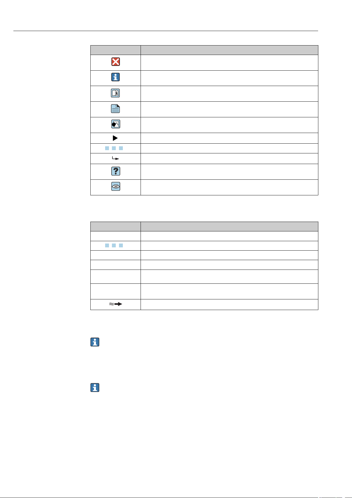
Symbol Meaning
Forbidden
Procedures, processes or actions that are forbidden.
Tip
Indicates additional information.
Reference to documentation
Reference to page
Reference to graphic
Notice or individual step to be observed
, 2., 3.… Series of steps
Result of a step
Help in the event of a problem
Visual inspection
1.2.4 Symbols in graphics
Symbol Meaning
1, 2, 3,... Item numbers
, 2., 3.… Series of steps
A, B, C, ... Views
A-A, B-B, C-C, ... Sections
Hazardous area
Safe area (non-hazardous area)
Flow direction
1.3 Documentation
For an overview of the scope of the associated Technical Documentation, refer to the
following:
• The W@M Device Viewer : Enter the serial number from the nameplate
(www.endress.com/deviceviewer)
• The Endress+Hauser Operations App: Enter the serial number from the nameplate
or scan the 2-D matrix code (QR code) on the nameplate.
For a detailed list of the individual documents along with the documentation code
6 Endress+Hauser
Page 7

Dosimag Modbus RS485 Document information
1.3.1 Standard documentation
Document type Purpose and content of the document
Technical Information Planning aid for your device
The document contains all the technical data on the device and provides
an overview of the accessories and other products that can be ordered for
the device.
Sensor Brief Operating Instructions Guides you quickly to the 1st measured value - Part 1
The Sensor Brief Operating Instructions are aimed at specialists with
responsibility for installing the measuring device.
• Incoming acceptance and product identification
• Storage and transport
• Installation
Transmitter Brief Operating
Instructions
Description of Device Parameters Reference for your parameters
Guides you quickly to the 1st measured value - Part 2
The Transmitter Brief Operating Instructions are aimed at specialists with
responsibility for commissioning, configuring and parameterizing the
measuring device (until the first measured value).
• Product description
• Installation
• Electrical connection
• Operation options
• System integration
• Commissioning
• Diagnostic information
The document provides a detailed explanation of each individual
parameter in the Expert operating menu. The description is aimed at
those who work with the device over the entire life cycle and perform
specific configurations.
The document provides Modbus-specific information for each individual
parameter in the Expert operating menu.
1.3.2 Supplementary device-dependent documentation
Additional documents are supplied depending on the device version ordered: Always
comply strictly with the instructions in the supplementary documentation. The
supplementary documentation is an integral part of the device documentation.
1.4 Registered trademarks
Modbus
Registered trademark of SCHNEIDER AUTOMATION, INC.
TRI-CLAMP
Registered trademark of Ladish & Co., Inc., Kenosha, USA
Applicator®, FieldCare®, DeviceCare
Registered or registration-pending trademarks of the Endress+Hauser Group
®
®
®
Endress+Hauser 7
Page 8

Basic safety instructions Dosimag Modbus RS485
2 Basic safety instructions
2.1 Requirements for the personnel
The personnel for installation, commissioning, diagnostics and maintenance must fulfill
the following requirements:
Trained, qualified specialists must have a relevant qualification for this specific function
‣
and task
Are authorized by the plant owner/operator
‣
Are familiar with federal/national regulations
‣
Before beginning work, the specialist staff must have read and understood the
‣
instructions in the Operating Instructions and supplementary documentation as well as
in the certificates (depending on the application)
Following instructions and basic conditions
‣
The operating personnel must fulfill the following requirements:
Being instructed and authorized according to the requirements of the task by the
‣
facility's owner-operator
Following the instructions in these Operating Instructions
‣
2.2 Designated use
Application and media
Depending on the version ordered, the measuring device can also measure potentially
explosive, flammable, poisonous and oxidizing media.
Measuring devices for use in hazardous areas, in hygienic applications or in applications
where there is an increased risk due to process pressure, are labeled accordingly on the
nameplate.
To ensure that the measuring device remains in proper condition for the operation time:
Only use the measuring device in full compliance with the data on the nameplate and
‣
the general conditions listed in the Operating Instructions and supplementary
documentation.
Check the nameplate to verify if the device ordered can be put to its intended use in the
‣
approval-related area (e.g. explosion protection, pressure vessel safety).
Use the measuring device only for media against which the process-wetted materials
‣
are adequately resistant.
If the measuring device is not operated at atmospheric temperature, compliance with
‣
the relevant basic conditions specified in the associated device documentation is
absolutely essential: "Documentation" section → 6.
Protect the measuring device permanently against corrosion from environmental
‣
influences.
Incorrect use
Non-designated use can compromise safety. The manufacturer is not liable for damage
caused by improper or non-designated use.
WARNING
L
Danger of breakage of the sensor due to corrosive or abrasive fluids or from
environmental conditions!
Verify the compatibility of the process fluid with the sensor material.
‣
Ensure the resistance of all fluid-wetted materials in the process.
‣
Keep within the specified pressure and temperature range.
‣
Verification for borderline cases:
For special fluids and fluids for cleaning, Endress+Hauser is glad to provide assistance
‣
in verifying the corrosion resistance of fluid-wetted materials, but does not accept any
8 Endress+Hauser
Page 9

Dosimag Modbus RS485 Basic safety instructions
warranty or liability as minute changes in the temperature, concentration or level of
contamination in the process can alter the corrosion resistance properties.
Residual risks
The external surface temperature of the housing can increase by max. 10 K due to the
power consumption of the electronic components. Hot process fluids passing through the
measuring device will further increase the surface temperature of the housing. The surface
of the sensor, in particular, can reach temperatures which are close to the fluid
temperature.
Possible burn hazard due to fluid temperatures!
For elevated fluid temperature, ensure protection against contact to prevent burns.
‣
2.3 Workplace safety
For work on and with the device:
Wear the required personal protective equipment according to federal/national
‣
regulations.
For welding work on the piping:
Do not ground the welding unit via the measuring device.
‣
If working on and with the device with wet hands:
It is recommended to wear gloves on account of the higher risk of electric shock.
‣
2.4 Operational safety
Risk of injury.
Operate the device in proper technical condition and fail-safe condition only.
‣
The operator is responsible for interference-free operation of the device.
‣
Conversions to the device
Unauthorized modifications to the device are not permitted and can lead to unforeseeable
dangers.
If, despite this, modifications are required, consult with Endress+Hauser.
‣
Repair
To ensure continued operational safety and reliability,
Carry out repairs on the device only if they are expressly permitted.
‣
Observe federal/national regulations pertaining to repair of an electrical device.
‣
Use original spare parts and accessories from Endress+Hauser only.
‣
2.5 Product safety
This measuring device is designed in accordance with good engineering practice to meet
state-of-the-art safety requirements, has been tested, and left the factory in a condition in
which it is safe to operate.
It meets general safety standards and legal requirements. It also complies with the EC
directives listed in the device-specific EC Declaration of Conformity. Endress+Hauser
confirms this by affixing the CE mark to the device.
2.6 IT security
We only provide a warranty if the device is installed and used as described in the
Operating Instructions. The device is equipped with security mechanisms to protect it
against any inadvertent changes to the device settings.
Endress+Hauser 9
Page 10

Basic safety instructions Dosimag Modbus RS485
IT security measures in line with operators' security standards and designed to provide
additional protection for the device and device data transfer must be implemented by the
operators themselves.
10 Endress+Hauser
Page 11
Dosimag Modbus RS485 Product description
1
2
3 Product description
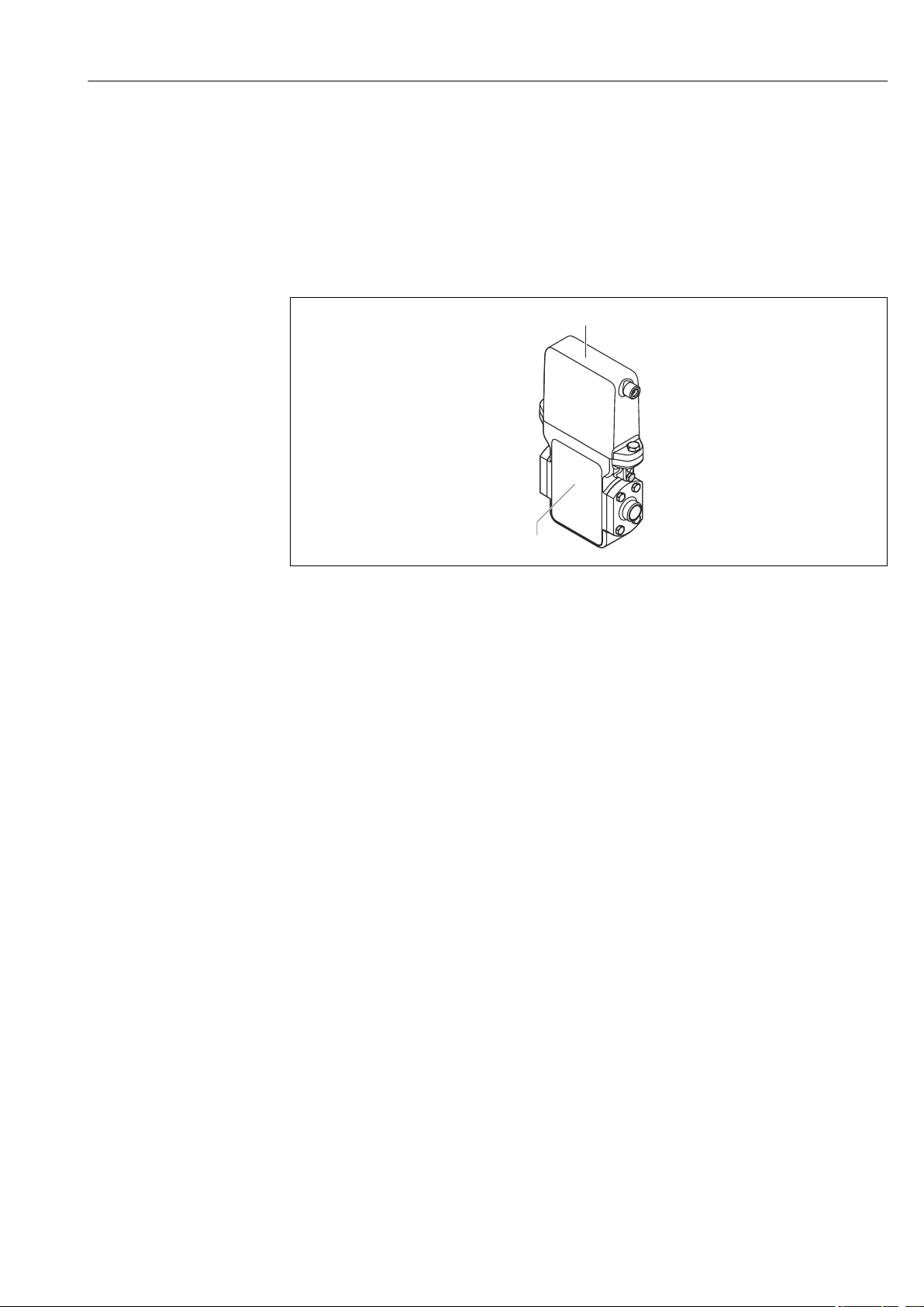
The device consists of a transmitter and a sensor.
The device is available as a compact version:
The transmitter and sensor form a mechanical unit.
3.1 Product design
1 Important components of the measuring device
1 Transmitter
2 Sensor
A0026624
Endress+Hauser 11
Page 12
Incoming acceptance and product identification Dosimag Modbus RS485
1
2
1
2
Order code:
Ser. no.:
Ext. ord. cd.:
i
i
Date:
4 Incoming acceptance and product
identification
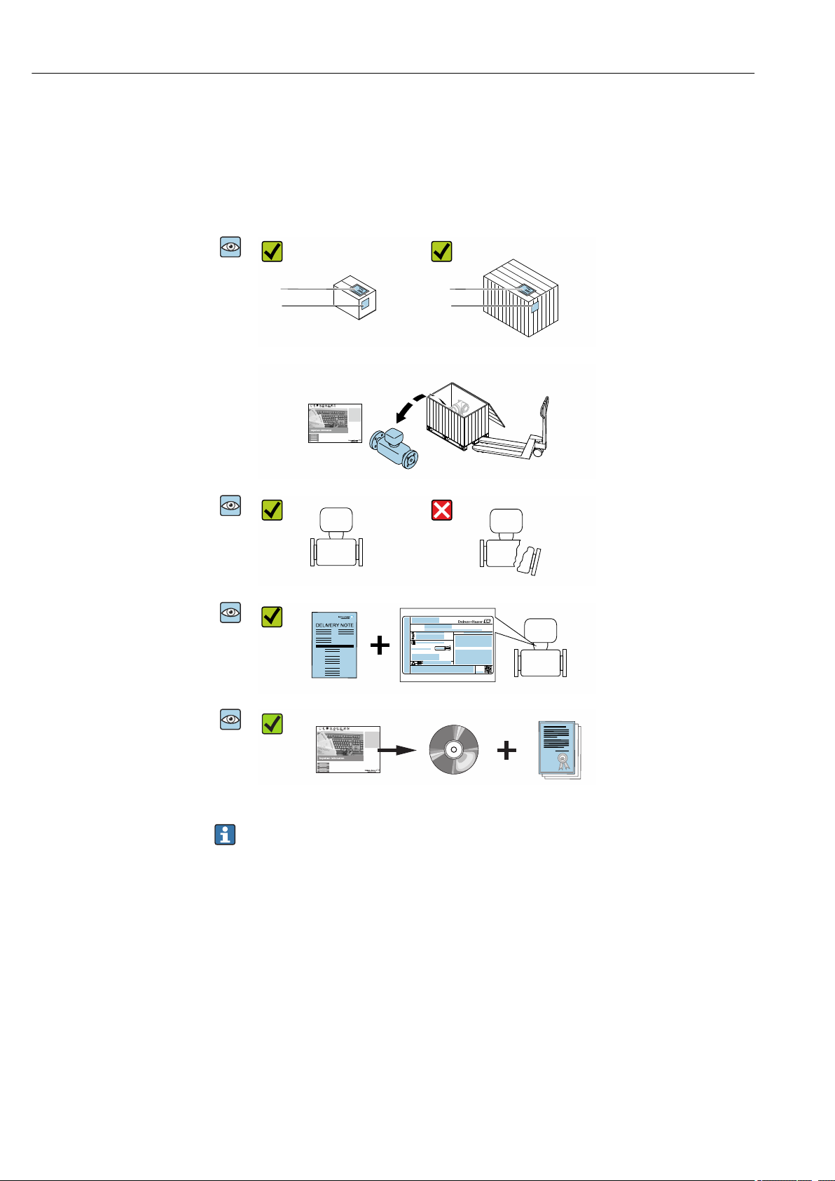
4.1 Incoming acceptance
Are the order codes on the
A0028673
delivery note (1) and the
product sticker (2) identical?
Are the goods undamaged?
A0028673
Do the nameplate data
A0028673
A0028673
match the ordering
information on the delivery
note?
Is the CD-ROM with the
Technical Documentation
(depends on device version)
and documents present?
• If one of the conditions is not satisfied, contact your Endress+Hauser Sales Center.
• Depending on the device version, the CD-ROM might not be part of the delivery!
The Technical Documentation is available via the Internet or via the Endress+Hauser
Operations App, see the "Product identification" section → 13.
4.2 Product identification
The following options are available for identification of the measuring device:
• Nameplate specifications
• Order code with breakdown of the device features on the delivery note
• Enter serial numbers from nameplates in W@M Device Viewer
(www.endress.com/deviceviewer): All information about the measuring device is
displayed.
• Enter the serial number from the nameplates into the Endress+Hauser Operations App
or scan the 2-D matrix code (QR code) on the nameplate with the Endress+Hauser
12 Endress+Hauser
Operations App: all the information for the measuring device is displayed.
Page 13
Dosimag Modbus RS485 Incoming acceptance and product identification
Ta:
Materials:
Tm:
Order Code:
TAG no.:
Ser. no.:
Ta+20°C/36°F
Dosimag
For installation and temp.
marking see control dwgs.
i
2
4
5
6
7
8
9
3
13
10
11
12
1
For an overview of the scope of the associated Technical Documentation, refer to the
following:
• The chapters "Additional standard documentation on the device" → 7 and
"Supplementary device-dependent documentation" → 7
• The W@M Device Viewer: Enter the serial number from the nameplate
(www.endress.com/deviceviewer)
• The Endress+Hauser Operations App: Enter the serial number from the nameplate or
scan the 2-D matrix code (QR code) on the nameplate.
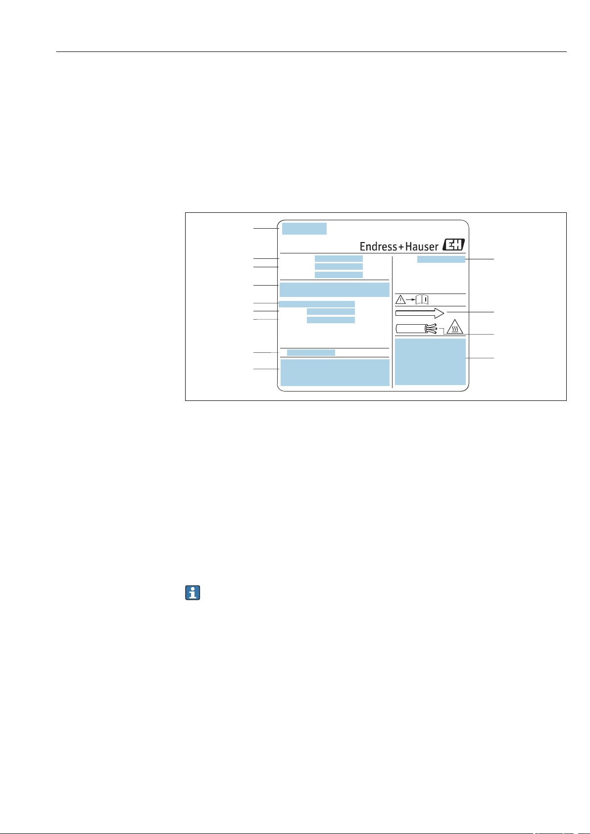
4.2.1 Sensor nameplate
A0003822
2 Example of sensor nameplate
1 Manufacturing location
2 Order code: see the specifications on the order confirmation for the meanings of the individual letters and
digits
3 Serial number
4 Supply voltage and power consumption
5 Process connection
6 Wetted materials
7 Maximum process temperature
8 Permitted ambient temperature range
9 Space reserved for additional information on the device version (approvals, certificates, etc.)
10 Degree of protection
11 Flow direction
12 Cable temperature
13 Space reserved for additional information on the device version (approvals, certificates, etc.)
Order code
The measuring device is reordered using the order code.
Extended order code
• The device type (product root) and basic specifications (mandatory features) are
always listed.
• Of the optional specifications (optional features), only the safety and approvalrelated specifications are listed (e.g. LA). If other optional specifications are also
ordered, these are indicated collectively using the # placeholder symbol (e.g. #LA#).
• If the ordered optional specifications do not include any safety and approval-related
specifications, they are indicated by the + placeholder symbol (e.g. XXXXXX-ABCDE
+).
Endress+Hauser 13
Page 14

Incoming acceptance and product identification Dosimag Modbus RS485
4.2.2 Symbols on measuring device
Symbol Meaning
WARNING!
This symbol alerts you to a dangerous situation. Failure to avoid this situation can result in serious
or fatal injury.
Reference to documentation
Refers to the corresponding device documentation.
Protective ground connection
A terminal which must be connected to ground prior to establishing any other connections.
14 Endress+Hauser
Page 15

Dosimag Modbus RS485 Storage and transport
5 Storage and transport
5.1 Storage conditions
Observe the following notes for storage:
• Store in the original packaging to ensure protection from shock.
• Do not remove protective covers or protective caps installed on process connections.
They prevent mechanical damage to the sealing surfaces and contamination in the
measuring tube.
• Protect from direct sunlight to avoid unacceptably high surface temperatures.
• Select a storage location where moisture cannot collect in the measuring device as
fungus and bacteria infestation can damage the lining.
• Store in a dry and dust-free place.
• Do not store outdoors.
Storage temperature→ 68
5.2 Transporting the product
Transport the measuring device to the measuring point in the original packaging.
Do not remove protective covers or caps installed on process connections. They
prevent mechanical damage to the sealing surfaces and contamination in the
measuring tube.
5.3 Packaging disposal
All packaging materials are environmentally friendly and 100% recyclable:
• Measuring device secondary packaging: polymer stretch film that conforms to EC
Directive 2002/95/EC (RoHS).
• Packaging:
– Wood crate, treated in accordance with ISPM 15 standard, which is confirmed by the
affixed IPPC logo.
or
– Carton in accordance with European Packaging Directive 94/62EC; recyclability is
confirmed by the affixed RESY symbol.
• Seaworthy packaging (optional): Wood crate, treated in accordance with ISPM 15
standard, which is confirmed by the affixed IPPC logo.
• Carrying and mounting hardware:
– Disposable plastic pallet
– Plastic straps
– Plastic adhesive strips
• Dunnage: Paper cushion
Endress+Hauser 15
Page 16
Installation Dosimag Modbus RS485
h
h
2
1
2 x DN³
5 x DN³
6 Installation
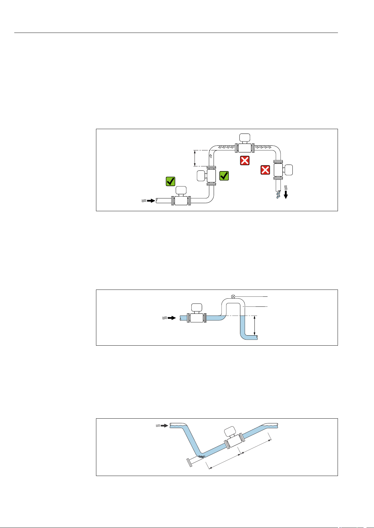
6.1 Installation conditions
6.1.1 Mounting position
Mounting location
A0029343
Preferably install the sensor in an ascending pipe, and ensure a sufficient distance to the
next pipe elbow: h ≥ 2 × DN
Installation in down pipes
Install a siphon with a vent valve downstream of the sensor in down pipes whose length h
≥ 5 m (16.4 ft). This precaution is to avoid low pressure and the consequent risk of
damage to the measuring tube. This measure also prevents the system losing prime.
A0028981
3 Installation in a down pipe
1 Vent valve
2 Pipe siphon
h Length of down pipe
Installation in partially filled pipes
A partially filled pipe with a gradient necessitates a drain-type configuration.
16 Endress+Hauser
A0029257
Page 17
Dosimag Modbus RS485 Installation
11
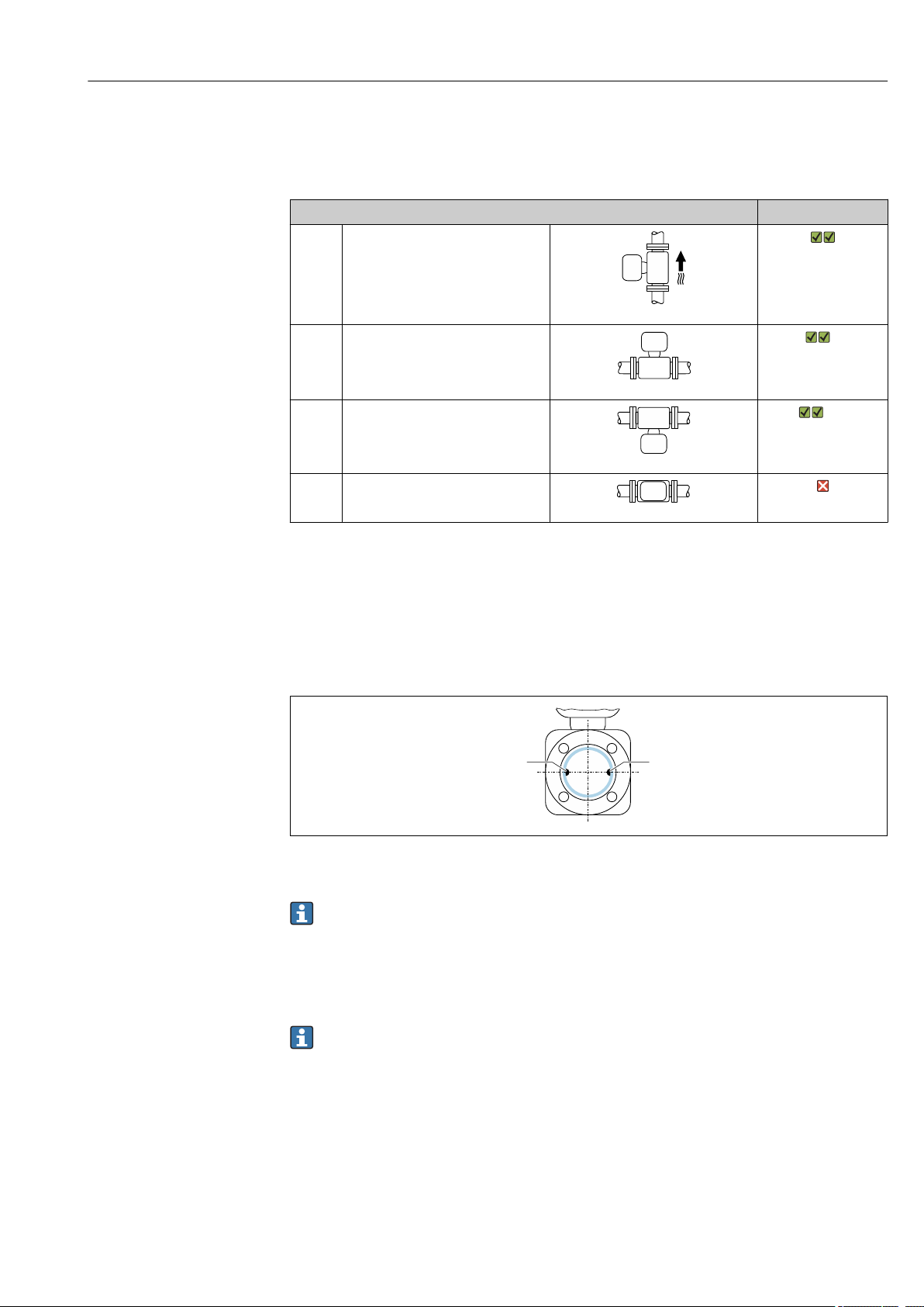
Orientation
The direction of the arrow on the sensor nameplate helps you to install the sensor
according to the flow direction (direction of medium flow through the piping).
Orientation Recommendation
A Vertical orientation
A0015591
B Horizontal orientation, transmitter at
top
C Horizontal orientation, transmitter at
bottom
D Horizontal orientation, transmitter at
side
A0015589
A0015590
A0015592
1)
2) 3)
1) Applications with low process temperatures may decrease the ambient temperature. To maintain the
minimum ambient temperature for the transmitter, this orientation is recommended.
2) Applications with high process temperatures may increase the ambient temperature. To maintain the
maximum ambient temperature for the transmitter, this orientation is recommended.
3) To prevent the electronics module from overheating in the case of a sharp rise in temperature (e.g. CIP- or
SIP processes), install the device with the transmitter component pointing downwards.
Horizontal
A0025817
1 Measuring electrodes for signal detection
Ideally, the measuring electrode plane should be horizontal. This prevents brief
insulation of the two measuring electrodes by entrained air bubbles.
Valves
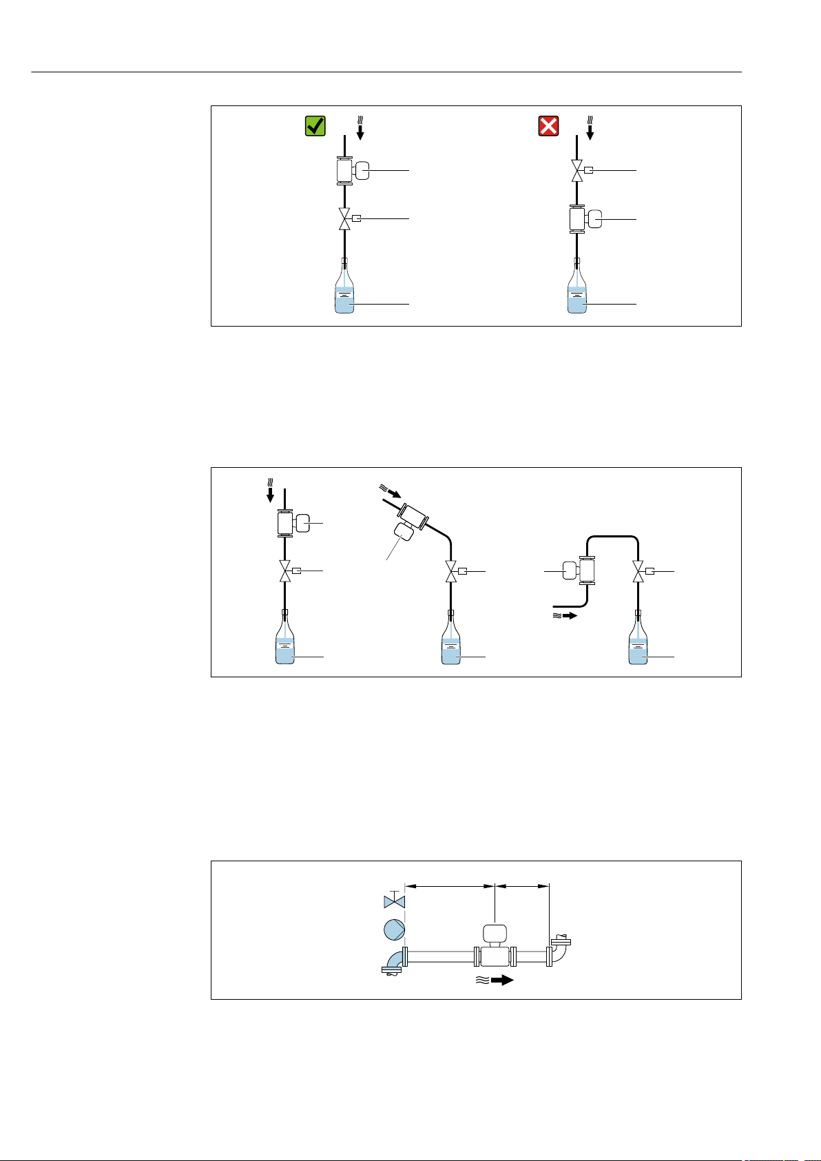
Never install the sensor downstream from a filling valve. If the sensor is completely empty
this corrupts the measured value.
Correct measurement is only possible if the pipe is completely full. Perform sample
fillings before commencing filling in production.
Endress+Hauser 17
Page 18
Installation Dosimag Modbus RS485
1
2
2
1
3 3
1
2
1
2
1
2
3 3 3
≥ 5 x DN
≥ 2 x DN
A0003768
1 Measuring device
2 Filling valve
3 Container
Filling systems
The pipe system must be completely full to ensure optimum measurement.
4 Filling system
1 Measuring device
2 Filling valve
3 Container
Inlet and outlet runs
If possible, install the sensor upstream from fittings such as valves, T-pieces or elbows.
Observe the following inlet and outlet runs to comply with accuracy specifications:
A0003795
A0028997
18 Endress+Hauser
Page 19
Dosimag Modbus RS485 Installation
L
Installation dimensions
For the dimensions and installation lengths of the device, see the "Technical
Information" document, "Mechanical construction" section.
6.1.2 Requirements from environment and process
Ambient temperature range
Transmitter –40 to +60 °C (–40 to +140 °F)
Sensor –40 to +60 °C (–40 to +140 °F)
Liner Do not exceed or fall below the permitted temperature range of the liner
→ 69.
Temperature tables
Observe the interdependencies between the permitted ambient and fluid
temperatures when operating the device in hazardous areas.
For detailed information on the temperature tables, see the separate document
entitled "Safety Instructions" (XA) for the device.
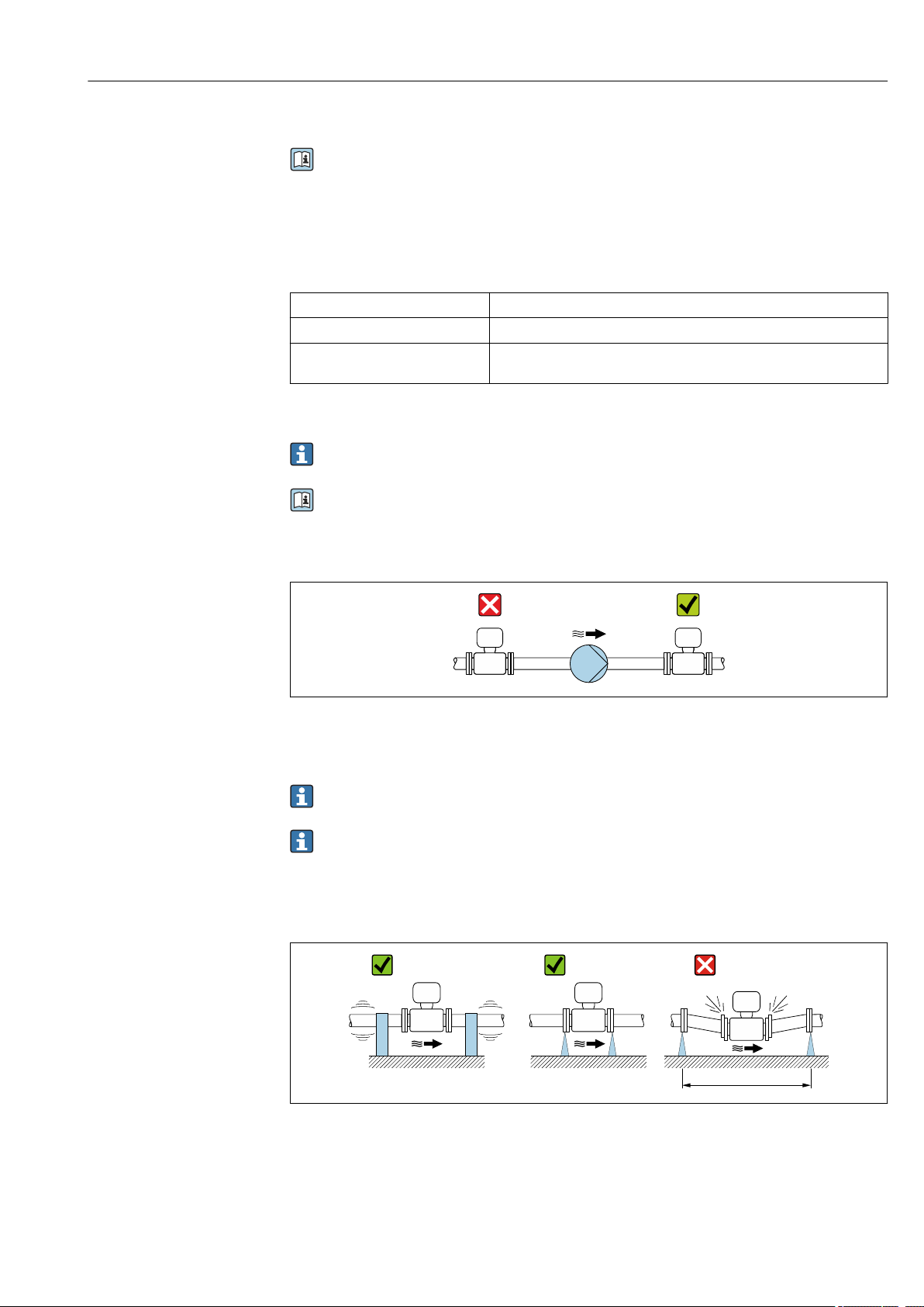
System pressure
A0028777
Never install the sensor on the pump suction side in order to avoid the risk of low pressure,
and thus damage to the liner.
Furthermore, install pulse dampers if reciprocating, diaphragm or peristaltic pumps
are used.
• For information on the liner's resistance to partial vacuum → 70
• For information on the shock resistance of the measuring system → 69
• For information on the vibration resistance of the measuring system → 69
Vibrations
A0029004
5 Measures to avoid device vibrations (L > 10 m (33 ft))
Endress+Hauser 19
Page 20
Installation Dosimag Modbus RS485
100
10
0.5
d / D
[mbar]
0.6 0.7 0.8 0.9
1 m/s
2 m/s
3 m/s
4 m/s
5 m/s
6 m/s
7 m/s
8 m/s
1
D
d
max. 8°
In the event of very strong vibrations, the pipe and sensor must be supported and fixed.
• For information on the shock resistance of the measuring system → 69
• For information on the vibration resistance of the measuring system → 69
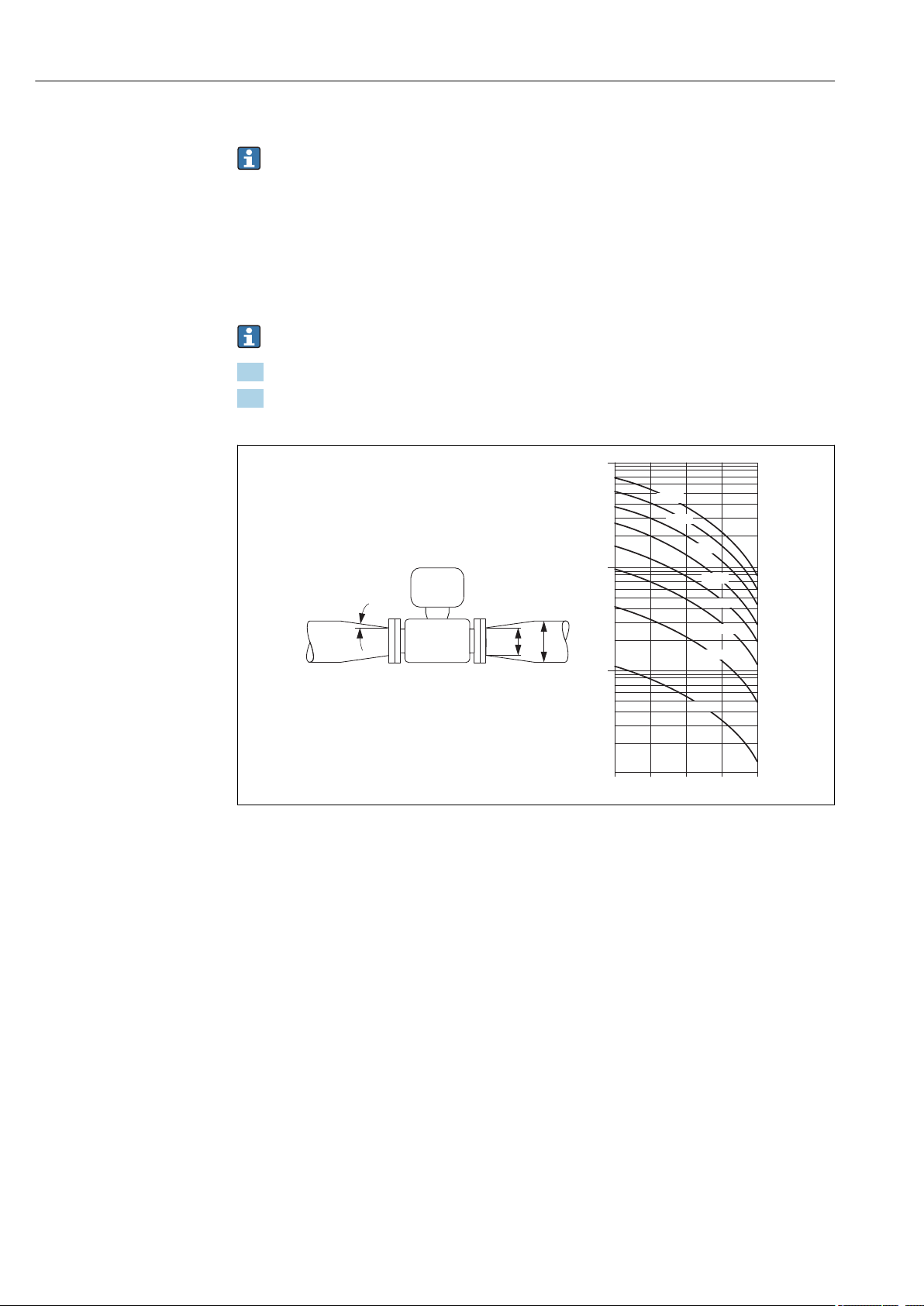
Adapters
Suitable adapters to DIN EN 545 (double-flange reducers) can be used to install the sensor
in larger-diameter pipes. The resultant increase in the rate of flow improves measuring
accuracy with very slow-moving fluids. The nomogram shown here can be used to
calculate the pressure loss caused by reducers and expanders.
The nomogram only applies to liquids with a viscosity similar to that of water.
1. Calculate the ratio of the diameters d/D.
2. From the nomogram read off the pressure loss as a function of flow velocity
(downstream from the reduction) and the d/D ratio.
6.1.3 Special mounting instructions
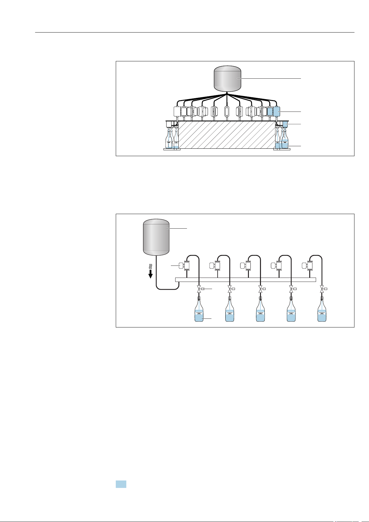
Information for filling systems
Correct measurement is possible only if the piping is completely filled. We therefore
recommend that some test batches be carried out prior to production batching.
20 Endress+Hauser
A0016359
Page 21
Dosimag Modbus RS485 Installation
4
3
2
1
1
3
4
2
Circular filling system
A0003761
1 Tank
2 Measuring device
3 Batching valve
4 Vessel
Linear filling system
1 Tank
2 Measuring device
3 Batching valve
4 Vessel
6.2 Mounting the measuring device
6.2.1 Required tools
For sensor
Endress+Hauser 21
For flanges and other process connections:
• Screws, nuts, seals etc. are not included in the scope of supply and must be provided by
the customer.
• Appropriate mounting tools
6.2.2 Preparing the measuring device
1. Remove all remaining transport packaging.
A0003762
Page 22

Installation Dosimag Modbus RS485
2. Remove any protective covers or protective caps present from the sensor.
3. Remove stick-on label on the electronics compartment cover.
6.2.3 Mounting the measuring device
WARNING
L
Danger due to improper process sealing!
Ensure that the inside diameters of the gaskets are greater than or equal to that of the
‣
process connections and piping.
Ensure that the gaskets are clean and undamaged.
‣
Install the gaskets correctly.
‣
Depending on the order option, the measuring device is supplied with or without preinstalled process connections. Pre-installed process connections are secured to the
measuring device using 4 hexagonal-headed bolts.
Ensure that the direction of the arrow on the nameplate of the sensor matches the flow
‣
direction of the fluid.
Depending on the application and pipe length, the measuring device may need to be
supported or additionally secured.
6.2.4 Welding the sensor into the pipe (welding connections)
WARNING
L
Risk of destroying the electronics!
Make sure that the welding system is not grounded via the sensor or transmitter.
‣
1. Tack-weld the sensor to secure it in the pipe. A suitable welding jig can be ordered
separately as an accessory → 74.
2. Release the screws on the process connection flange and remove the sensor, along
with the seal, from the pipe.
3. Weld the process connection into the pipe.
4. Reinstall the sensor in the pipe, and in doing so make sure that the seal is clean and
in the right position.
• If thin-walled pipes carrying food are welded correctly, the seal is not damaged by
the heat even when mounted. However, it is recommended to disassemble the
sensor and seal.
• It must be possible to open the pipe by approx. 8 mm (0.31 in).
6.2.5 Cleaning with pigs
It is essential to take the internal diameters of the measuring tube and process connection
into account when cleaning with pigs. All the dimensions and lengths of the sensor and
transmitter are provided in the separate "Technical Information" document.
22 Endress+Hauser
Page 23

Dosimag Modbus RS485 Installation
6.2.6 Seals
When mounting the process connections, make sure that the seals in question are dry,
clean, undamaged and correctly centered.
• The screws must be firmly tightened. The process connection forms a metal
connection with the sensor, which ensures a defined compression of the seal.
• Depending on the application the seals should be replaced periodically, particularly
if molded seals are used (aseptic version)!
The interval between changes depends on the frequency of the cleaning cycles, the
cleaning temperature and the medium temperature.
Replacement seals can be ordered as an accessory.
6.2.7 Nominal diameter and flow
The diameter of the pipe and the flow rate determine the nominal diameter of the sensor.
The optimum flow velocity is between 1 to 4 m/s (3.28 to 13.12 ft/s). The velocity of flow
(v), moreover, has to be matched to the physical properties of the fluid:
• v < 2 m/s (6.56 ft/s): For abrasive media such as cleaning agents etc.
• v > 2 m/s (6.56 ft/s): For media that produce buildup, such as oil and liquids that
contain sugar
A necessary increase in the flow velocity can be achieved by reducing the sensor
nominal diameter.
Flow characteristic values → 64
6.3 Post-installation check
Is the device undamaged (visual inspection)?
Does the measuring device conform to the measuring point specifications?
For example:
• Process temperature
• Process pressure→ 70
• Ambient temperature → 68
• Measuring range
Horizontal position of the measuring electrode plane?
Has the correct orientation for the sensor been selected ?
• According to sensor type
• According to medium temperature
• According to medium properties (outgassing, with entrained solids)
Does the arrow on the sensor nameplate match the direction of flow of the fluid through the
piping ?
Are the measuring point identification and labeling correct (visual inspection)?
Is the measuring device adequately protected against vibration (attachment, support)?
Are the inlet and outlet runs to respected?→ 18
Endress+Hauser 23
Page 24

Electrical connection Dosimag Modbus RS485
7 Electrical connection
The measuring device does not have an internal circuit breaker. For this reason,
assign the measuring device a switch or power-circuit breaker so that the power
supply line can be easily disconnected from the mains.
7.1 Connection conditions
7.1.1 Requirements for connecting cable
The connecting cables provided by the customer must fulfill the following requirements.
Electrical safety
In accordance with applicable federal/national regulations.
Permitted temperature range
• –40 °C (–40 °F) to +80 °C (+176 °F)
• Minimum requirement: cable temperature range ≥ ambient temperature +20 K
Signal cable
Cables are not included in the scope of delivery; they can be ordered as an accessory
→ 62.
Status input and switch output (batch)
Standard installation cable is sufficient.
Modbus RS485
• The electrical connection of the shield to the device housing must be properly
implemented (e.g. using a knurled nut).
• Observe the following with regard to cable loading:
– Voltage drop due to the cable length and cable type.
– Valve performance.
Total length of cable in the Modbus network ≤ 50 m
Use a shielded cable.
Example:
Terminated device plug with cable: Lumberg RKWTH 8-299/10
Total length of cable in the Modbus network > 50 m
Use shielded twisted pair cable for RS485 applications.
Example:
• Cable: Belden item no. 9842 (for 4-wire version, the same cable can be used for the
power supply)
• Terminated device plug: Lumberg RKCS 8/9 (shieldable version)
7.1.2 Terminal assignment
Connection is solely by means of device plug:
There are different device versions available. Order code for "Output, input":
• Option 4: Modbus RS485, 1 status output (batch),1 status input → 25
• Option 5: Modbus RS485, 2 status outputs (batch),1 status input → 26
• Option 6: Modbus RS485 (custody transfer mode)→ 27
24 Endress+Hauser
Page 25
Dosimag Modbus RS485 Electrical connection
BA D
C
RSE 5
M12x1
RSE 8
M12x1
C
8
A DB
1
2
3
4
5
6
7
2
3
1
5
E
4
V1
+
-
7
2
4
6
1
3
5
8
7
2
4
6
1
3
5
8
1
2
4
3
5
1
2
4
3
5
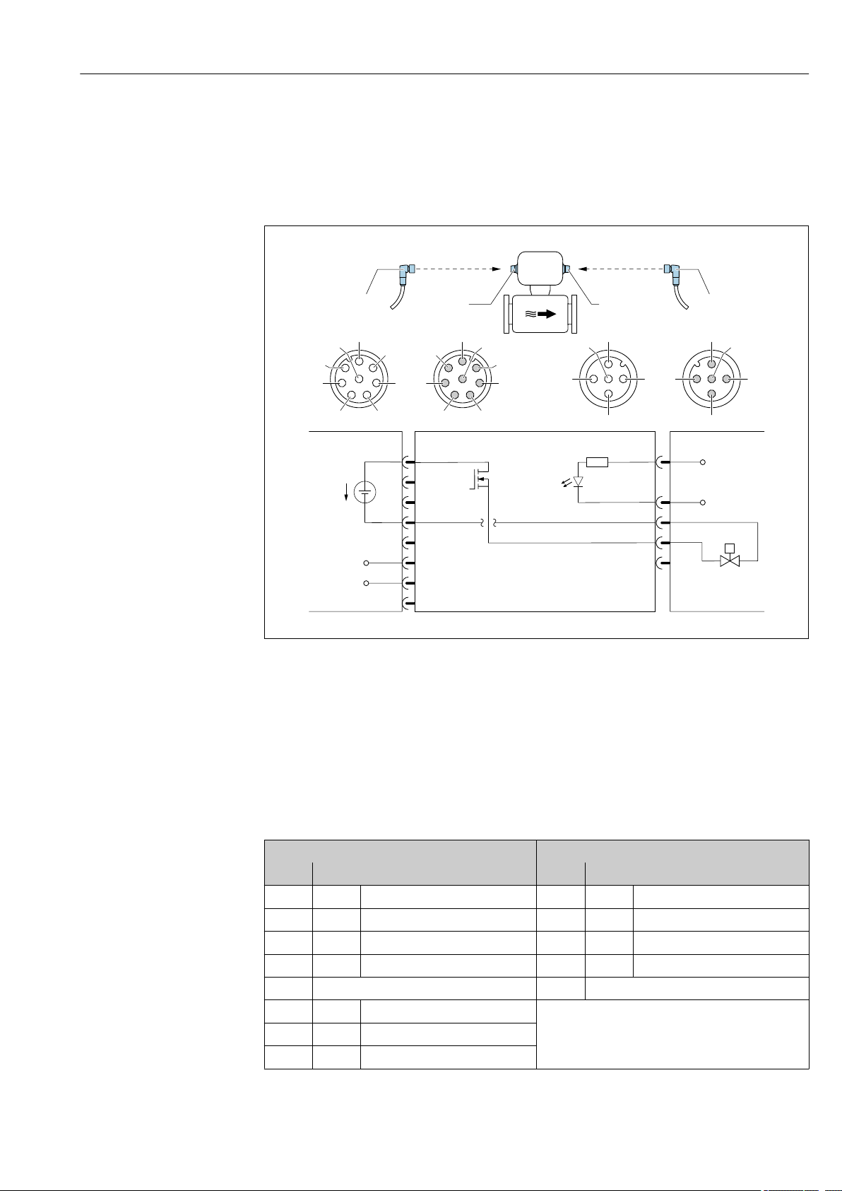
7.1.3 Pin assignment, device plug
Device version: Modbus RS485, status output and status input
Order code for "Output, input", option 4:
Modbus RS485, 1 switch output (batch), 1 status input
A0032570
6 Connection to device
A Coupling: Supply voltage, Modbus RS485
B Connector: Supply voltage, Modbus RS485
C Coupling: Switch output (batch), status input
D Connector: Switch output (batch), status input
E PELV or SELV power supply
V1 Valve 1 (batch)
1 to8Pin assignment
Endress+Hauser 25
Pin assignment
Connection: Coupling (A) – Connector (B) Connection: Coupling (C) – Connector (D)
Pin Assignment Pin Assignment
1 L+ Supply voltage 1 + Status input
2 + Service interface RX 2 – Status input
3 + Service interface TX 3 – Switch output (batch)
4 L- Supply voltage 4 + Switch output (batch)
5 Not assigned 5 Not assigned
6 A Modbus RS485
7 B Modbus RS485
8 – Service interface GND
Page 26
Electrical connection Dosimag Modbus RS485
C
1
2
3
4
5
6
7
8
2
3
1
5
A
4
D
V2
V1
B
BA D
C
RSE 5
M12x1
RSE 8
M12x1
E
+
-
7
2
4
6
1
3
5
8
7
2
4
6
1
3
5
8
1
2
4
3
5
1
2
4
3
5
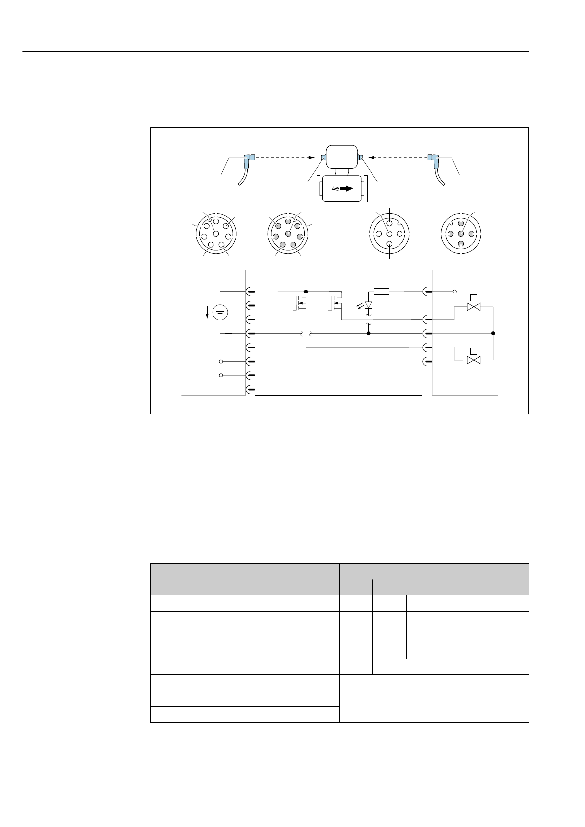
Device version: Modbus RS485 , 2 status outputs and status input
Order code for "Output, input", option 5:
Modbus RS485, 2 switch outputs (batch), 1 status input
7 Connection to device
A Coupling: Supply voltage, Modbus RS485
B Connector: Supply voltage, Modbus RS485
C Coupling: Switch outputs (batch), status input
D Connector: Switch outputs (batch), status input
E PELV or SELV power supply
V1 Valve (batch), level 1
V2 Valve (batch), level 2
1 to8Pin assignment
Pin assignment
Pin Assignment Pin Assignment
1 L+ Supply voltage 1 + Status input
2 + Service interface RX 2 + Switch output (batch) 2
3 + Service interface TX 3 – Switch outputs, status input
4 L- Supply voltage 4 + Switch output (batch) 1
5 Not assigned 5 Not assigned
6 A Modbus RS485
7 B Modbus RS485
8 – Service interface GND
Connection: Coupling (A) – Connector (B) Connection: Coupling (C) – Connector (D)
26 Endress+Hauser
A0032571
Page 27
Dosimag Modbus RS485 Electrical connection
C
1
2
3
4
5
6
7
8
A
DB
BA D
C
RSE 8
M12x1
E
+
-
7
2
4
6
1
3
5
8
7
2
4
6
1
3
5
8
1
2
4
3
5
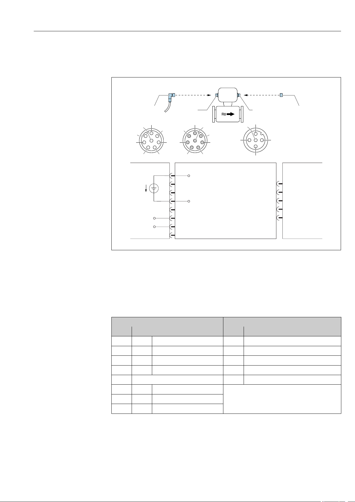
Device version: Modbus RS485 (custody transfer mode)
Order code for "Output, input", option 6 (device version for custody transfer mode):
Modbus RS485
A0032572
8 Connection to device
A Coupling: Supply voltage, Modbus RS485
B Connector: Supply voltage, Modbus RS485
C Coupling at device
D Connector: Dongle (hardware write protection for custody transfer mode)
E PELV or SELV power supply
Pin assignment
Connection: Coupling (A) – Connector (B) Connection: Coupling (C) – Connector (D)
Pin Assignment Pin Assignment
1 L+ Supply voltage 1 NC
2 + Service interface RX 2 NC
3 + Service interface TX 3 NC
4 L- Supply voltage 4 +
5 Not assigned 5 -
6 A Modbus RS485
7 B Modbus RS485
8 – Service interface GND
Endress+Hauser 27
Page 28
Electrical connection Dosimag Modbus RS485
B
A
D
C
7.1.4 Requirements for the supply unit
Supply voltage
DC 24 V (nominal voltage: DC 20 to 30 V)
• The power unit must be tested to ensure that it meets safety requirements (e.g.
PELV, SELV).
• The supply voltage must not exceed a maximum short-circuit current of 50 A.
7.2 Connecting the measuring device
NOTICE
Limitation of electrical safety due to incorrect connection!
Have electrical connection work carried out by correspondingly trained specialists only.
‣
Observe applicable federal/national installation codes and regulations.
‣
Comply with local workplace safety regulations.
‣
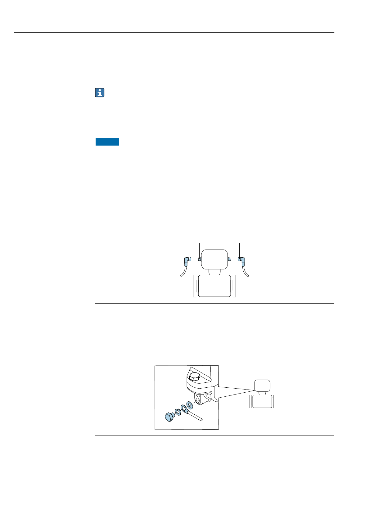
7.2.1 Connecting the transmitter
Connection by means of device plug
Connection is solely by means of device plug.
A, C Coupling
B, D Plug
Grounding
Grounding is by means of a cable socket.
A0032534
28 Endress+Hauser
7.3 Ensuring the degree of protection
The measuring device fulfills all the requirements for IP67 degree of protection, Type 4X
enclosure.
A0003838
Page 29

Dosimag Modbus RS485 Electrical connection
To guarantee IP67 degree of protection, Type 4X enclosure, carry out the following steps
after the electrical connection:
Tighten all device plugs.
‣
7.4 Post-connection check
Is the device undamaged (visual inspection)?
Does the supply voltage in the system match the specifications on the device's nameplate?
Do the cables used comply with the necessary specifications?
Are the maximum values for voltage and current at the pulse and status output being observed?
→ 65
Endress+Hauser 29
Page 30
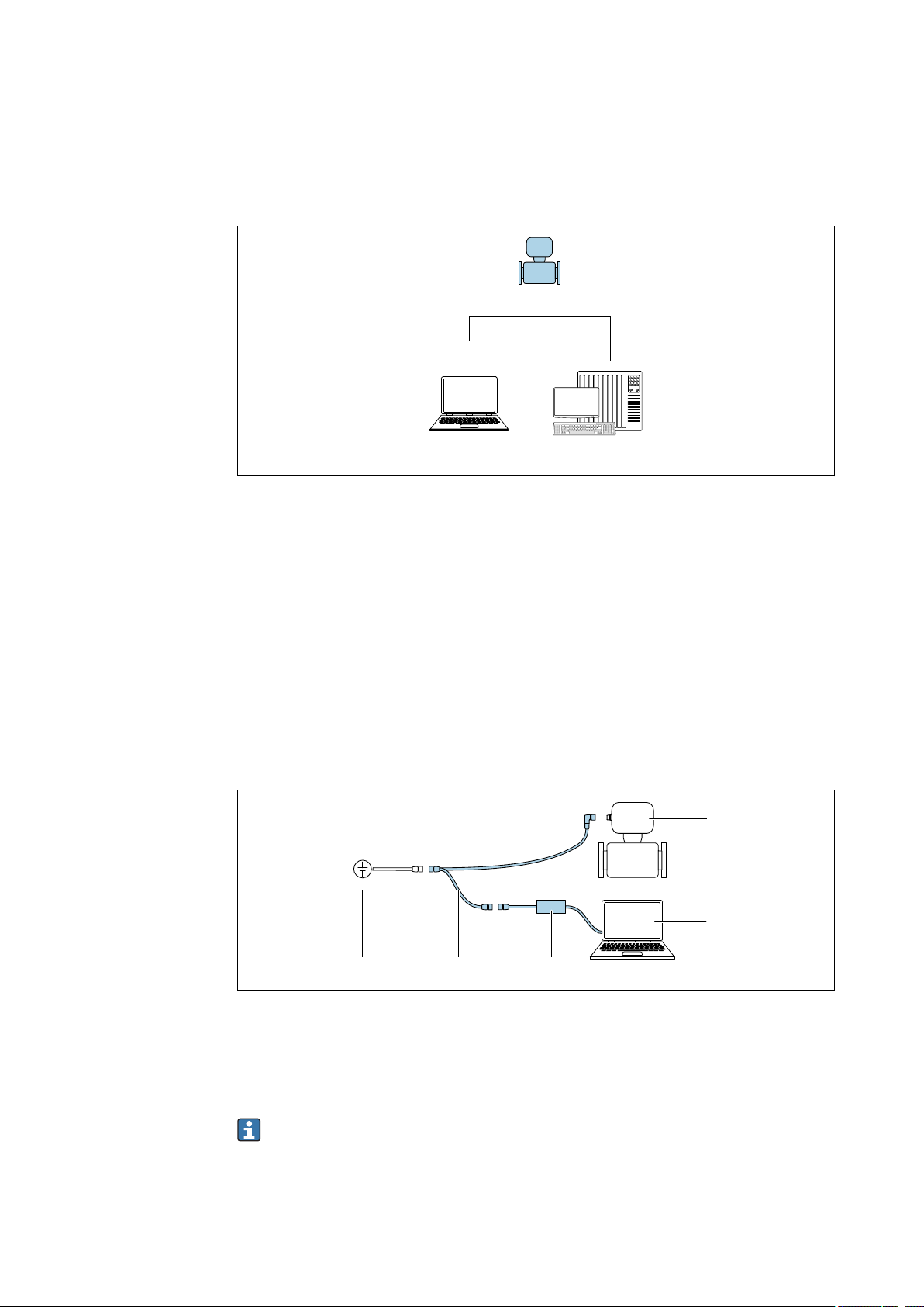
Operation options Dosimag Modbus RS485
1
2
+
-
1 2 3
4
5
8 Operation options
8.1 Overview of operation options
A0017760
1 Computer with "FieldCare" or "DeviceCare" operating tool
2 Control system (e.g. PLC)
8.2 Access to the operating menu via the operating tool
8.2.1 Connecting the operating tool
Using the service adapter and Commubox FXA291
Operation and configuration can be performed using the Endress+Hauser FieldCare or
DeviceCare service and configuration software.
The device is connected to the USB port of the computer via the service adapter and
Commubox FXA291.
1 Supply voltage 24 V DC
2 Service adapter
3 Dosimag
4 Commubox FXA291
5 Computer with "FieldCare" or "DeviceCare" operating tool
A0032567
The service adapter, cable and Commubox FXA291 are not included in the delivery.
These components can be ordered as accessories → 62.
30 Endress+Hauser
Page 31

Dosimag Modbus RS485 Operation options
8.2.2 FieldCare
Function scope
FDT-based plant asset management tool from Endress+Hauser. It can configure all smart
field devices in a system and helps you manage them. By using the status information, it is
also a simple but effective way of checking their status and condition.
Access is via:
Service adapter and Commubox FXA291
Typical functions:
• Configuring parameters of transmitters
• Loading and saving device data (upload/download)
• Documentation of the measuring point
• Visualization of the measured value memory (line recorder) and event logbook
For additional information about FieldCare, see Operating Instructions BA00027S
and BA00059S
Source for device description files
See information → 33
Establishing a connection
Service adapter, Commubox FXA291 and "FieldCare" operating tool
1. Start FieldCare and launch the project.
2. In the network: Add a device.
The Add device window opens.
3. Select the CDI Communication FXA291 option from the list and press OK to
confirm.
4. Right-click CDI Communication FXA291 and select the Add device option in the
context menu that opens.
5. Select the desired device from the list and press OK to confirm.
6. Establish the online connection to the device.
For additional information, see Operating Instructions BA00027S and BA00059S
Endress+Hauser 31
Page 32
Operation options Dosimag Modbus RS485
6
5
32
1
Xxxxxx/…/…/
7
P
P
+
–
P
–
P
+
+
+
+
+
+
4
8 9
10
11
Xxxxxxx
GoodStatus:
Device tag:
Xxxxxxx
Device name:
Mass flow:
12.34
kg/h
Volume flow:
12.34
m /h³
Mass flow unit:
Volume flow unit:
kg/h
m /h³
Access status tooling
Operation
Setup
Xxxxxx
Mass flow unit
Volume flow unit
Select medium
Device tag
…
…
Advanced setup
Diagnostics
Expert
Maintenance
kg/h
m /h³
Xxxxxx
System units
User interface
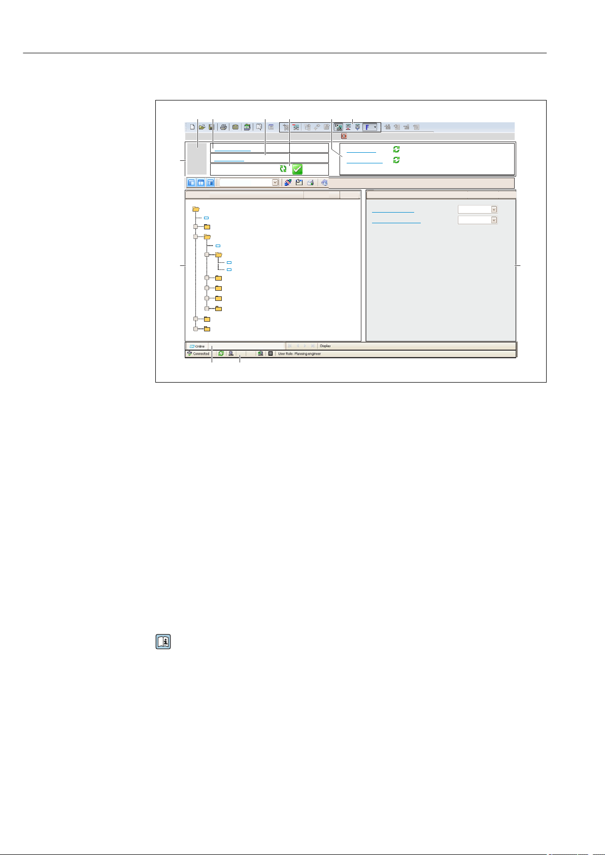
1 Header
2 Picture of device
3 Device name
4 Tag name
5 Status area with status signal
6 Display area for current measured values
7 Edit toolbar with additional functions such as save/restore, event list and create documentation
8 Navigation area with operating menu structure
9 Working area
10 Range of action
11 Status area
8.2.3 DeviceCare
Function scope
Tool to connect and configure Endress+Hauser field devices.
32 Endress+Hauser
The fastest way to configure Endress+Hauser field devices is with the dedicated
"DeviceCare" tool. Together with the device type managers (DTMs) it presents a convenient,
comprehensive solution.
For details, see Innovation Brochure IN01047S
Source for device description files
See information → 33
A0021051-EN
Page 33
Dosimag Modbus RS485 System integration
9 System integration
9.1 Overview of device description files
9.1.1 Current version data for the device
Firmware version 03.00.zz • On the title page of the Operating instructions
• On transmitter nameplate
• Firmware version
Diagnostics menu → Device information submenu
→ Firmware version parameter
Release date of firmware version 05.2015 ---
For an overview of the different firmware versions for the device → 58
9.1.2 Operating tools
The suitable device description file for the individual operating tools is listed in the table
below, along with information on where the file can be acquired.
Operating tool Sources for obtaining device descriptions
FieldCare • www.endress.com → Download Area
• CD–ROM (contact Endress+Hauser)
• DVD (contact Endress+Hauser)
DeviceCare • www.endress.com → Download Area
• CD–ROM (contact Endress+Hauser)
• DVD (contact Endress+Hauser)
9.2 Modbus RS485 information
9.2.1 Function codes
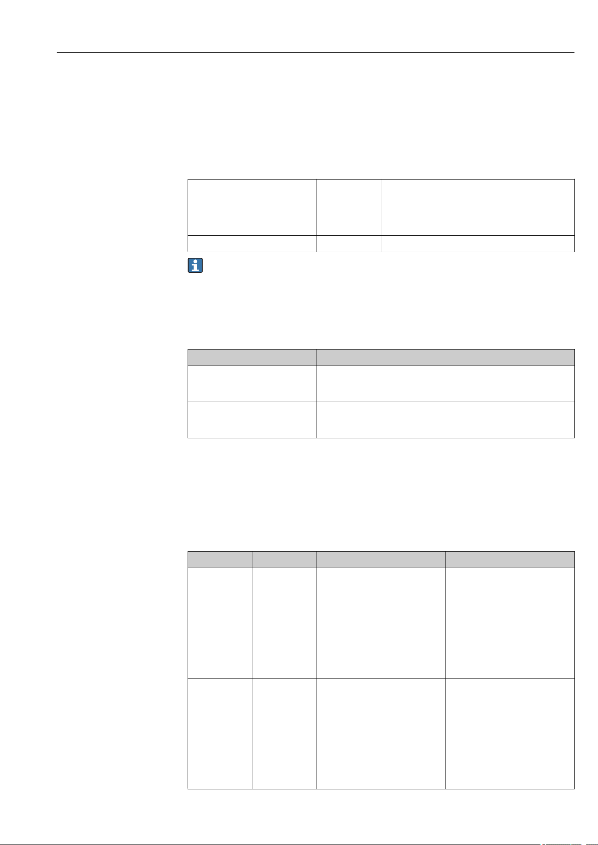
Function codes are used to define which read or write action is carried out via the Modbus
protocol. The measuring device supports the following function codes:
Code Name Description Application
03 Read holding
register
04 Read input
register
Master reads one or more Modbus
registers from the device.
A maximum of 125 consecutive
registers can be read with 1
telegram: 1 register = 2 bytes
The measuring device does
not make a distinction
between function codes 03
and 04; these codes therefore
yield the same result.
Master reads one or more Modbus
registers from the device.
A maximum of 125 consecutive
registers can be read with 1
telegram: 1 register = 2 bytes
The measuring device does
not make a distinction
between function codes 03
and 04; these codes therefore
yield the same result.
Read device parameters with read
and write access
Example:
Read volume flow
Read device parameters with read
access
Example:
Read totalizer value
Endress+Hauser 33
Page 34

System integration Dosimag Modbus RS485
Code Name Description Application
06 Write single
registers
08 Diagnostics Master checks the communication
16 Write multiple
registers
23 Read/Write
multiple
registers
Master writes a new value to one
Modbus register of the measuring
device.
Use function code 16 to write
multiple registers with just 1
telegram.
connection to the measuring device.
The following "Diagnostics codes"
are supported:
• Sub-function 00 = Return query
data (loopback test)
• Sub-function 02 = Return
diagnostics register
Master writes a new value to
multiple Modbus registers of the
device.
A maximum of 120 consecutive
registers can be written with 1
telegram.
If the required device
parameters are not available
as a group, yet must
nevertheless be addressed
with a single telegram, use
Modbus data map → 34
Master reads and writes a
maximum of 118 Modbus registers
of the measuring device
simultaneously with 1 telegram.
Write access is executed before
read access.
Write only 1 device parameter
Example: reset totalizer
Write multiple device parameters
Write and read multiple device
parameters
Example:
• Read mass flow
• Reset totalizer
Broadcast messages are only allowed with function codes 06, 16 and 23.
9.2.2 Register information
For an overview of Modbus-specific information relating to the individual device
parameters: Description of device parameters.
9.2.3 Response time
Response time of the measuring device to the request telegram of the Modbus master:
typically 3 to 5 ms
9.2.4 Modbus data map
Function of the Modbus data map
The device offers a special memory area, the Modbus data map (for a maximum of 16
device parameters), to allow users to call up multiple device parameters via Modbus RS485
and not only individual device parameters or a group of consecutive device parameters.
Grouping of device parameters is flexible and the Modbus master can read or write to the
entire data block simultaneously with a single request telegram.
34 Endress+Hauser
Page 35
Dosimag Modbus RS485 System integration
Structure of the Modbus data map
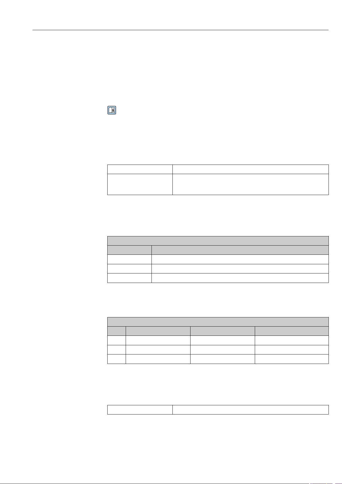
The Modbus data map consists of two data sets:
• Scan list: Configuration area
The device parameters to be grouped are defined in a list in that their Modbus RS485
register addresses are entered in the list.
• Data area
The measuring device reads out the register addresses entered in the scan list cyclically
and writes the associated device data (values) to the data area.
For an overview of device parameters with their individual Modbus register address,
please refer to the additional document on Modbus RS485 register information
Scan list configuration
For configuration, the Modbus RS485 register addresses of the device parameters to be
grouped must be entered in the scan list. Please note the following basic requirements of
the scan list:
Max. entries 16 device parameters
Supported device parameters Only parameters with the following characteristics are supported:
• Access type: read or write access
• Data type: float or integer
Configuring the scan list via FieldCare
Carried out using the operating menu of the measuring device:
Expert → Communication → Modbus data map → Scan list register 0 -15
Scan list
No. Configuration register
0 Scan list register 0
... ...
15 Scan list register 15
Configuring the scan list via Modbus RS485
Carried out using register addresses 5001 - 5016
Scan list
No. Modbus RS485 register Data type Configuration register
0 5001 Integer Scan list register 0
... ... Integer ...
15 5016 Integer Scan list register 15
Reading out data via Modbus RS485
The Modbus master accesses the data area of the Modbus data map to read out the current
values of the device parameters defined in the scan list.
Master access to data area Via register addresses 5051-5081
Endress+Hauser 35
Page 36

System integration Dosimag Modbus RS485
Data area
Device parameter value Modbus RS485
register
Value of scan list register 0 5051 Integer/float Read/write
Value of scan list register 1 5053 Integer/float Read/write
Value of scan list register ... ... ... ...
Value of scan list register 15 5081 Integer/float Read/write
* Data type depends on the device parameters entered in the scan list.
** Data access depends on the device parameters entered in the scan list. If the device parameter entered
supports read and write access, the parameter can also be accessed via the data area.
Data type* Access**
36 Endress+Hauser
Page 37
Dosimag Modbus RS485 Commissioning
10 Commissioning
10.1 Function check
Before commissioning the measuring device:
Make sure that the post-installation and post-connection checks have been performed.
‣
• "Post-installation check" checklist → 23
• "Post-connection check" checklist → 29
10.2 Switching on the measuring device
The function check has been completed successfully.
‣
Switch on the supply voltage.
The measuring device runs through internal test functions.
The device is operational and operation commences.
If the device does not start up successfully, depending on the cause, a diagnostic
message is displayed in the system asset management tool "FieldCare" .
10.3 Establishing a connection via FieldCare
• For FieldCare connection
• For establishing a connection via FieldCare → 31
• For FieldCare user interface → 32
10.4 Configuring the measuring device
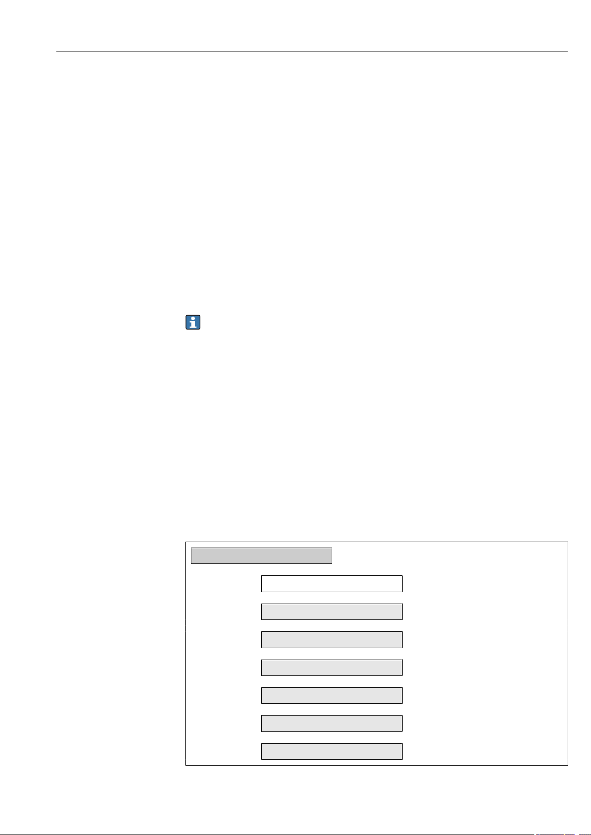
The Setup menuwith its submenus contains all the parameters needed for standard
operation.
Navigation
"Setup" menu
Setup
Device tag
System units
‣
Communication
‣
→ 38
→ 38
→ 41
Status input
‣
Batch output
‣
Low flow cut off
‣
Advanced setup
‣
Endress+Hauser 37
→ 38
→ 39
→ 42
→ 42
Page 38
Commissioning Dosimag Modbus RS485
10.4.1 Defining the tag name
To enable fast identification of the measuring point within the system, you can enter a
unique designation using the Device tag parameter and thus change the factory setting.
• The number of characters displayed depends on the characters used.
• Enter the tag name in the "FieldCare" operating tool → 32
Navigation
"Setup" menu → Device tag
Parameter overview with brief description
Parameter Description User entry Factory setting
Device tag Enter the name for the measuring point. Max. 16 characters such as
letters, numbers or special
characters (e.g. @, %, /).
Dosimag
10.4.2 Setting the system units
In the System units submenu the units of all the measured values can be set.
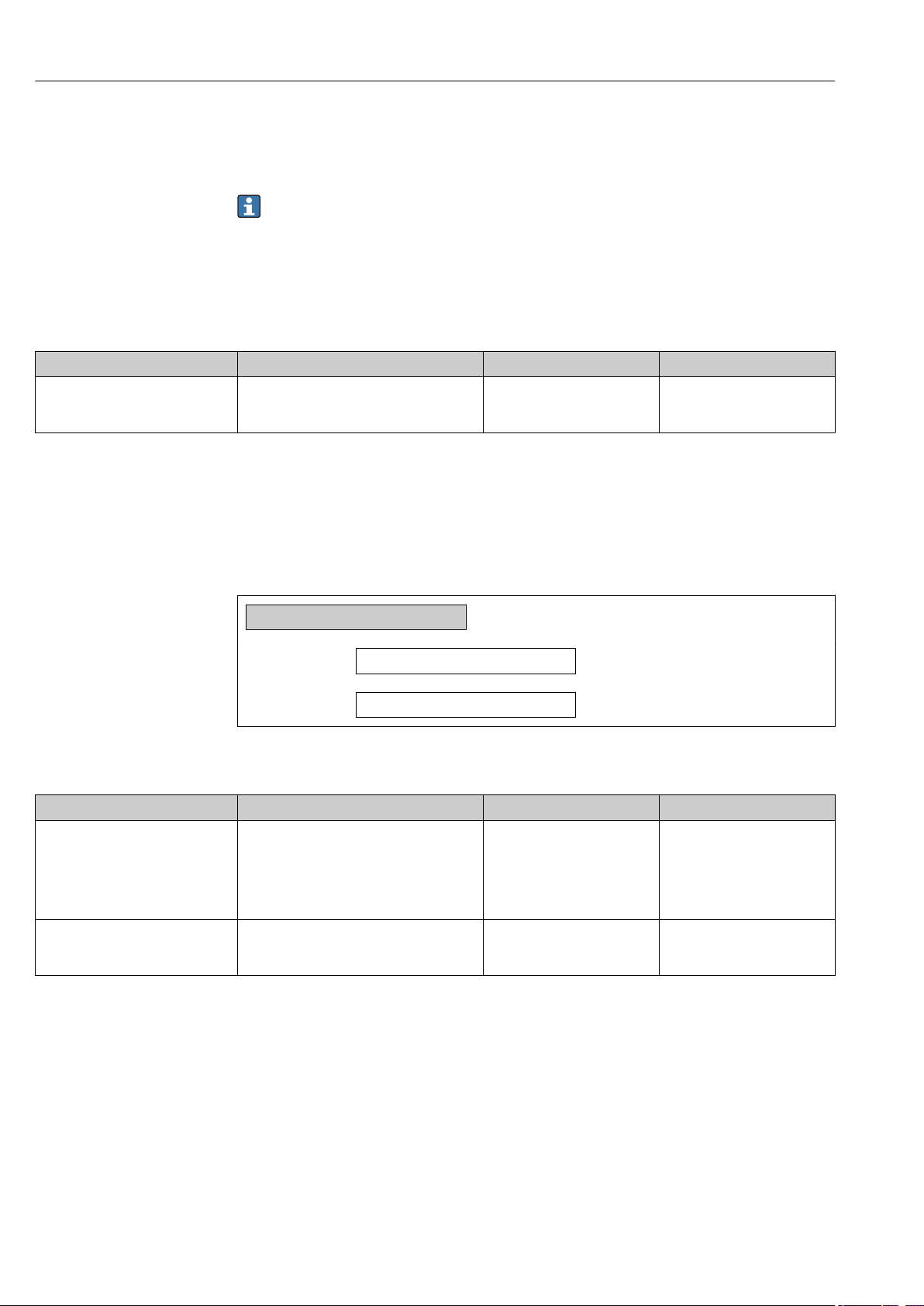
Navigation
"Setup" menu → System units
System units
‣
Volume flow unit
Volume unit
Parameter overview with brief description
Parameter Description Selection Factory setting
Volume flow unit Select volume flow unit.
Result
The selected unit applies for:
• Low flow cut off
• Simulation process variable
Volume unit Select volume unit. Unit choose list Country-specific:
Unit choose list Country-specific:
• ml/s
• fl oz/s (us)
• ml
• fl oz (us)
10.4.3 Configuring the status input
The Status input submenu guides you systematically through all the parameters that have
to be set for configuring the input.
38 Endress+Hauser
Page 39

Dosimag Modbus RS485 Commissioning
Navigation
"Setup" menu → Status input
Structure of the submenu
Status input
‣
Assign status input
Active level
Response time status input
Parameter overview with brief description
Parameter Prerequisite Description Selection / User
Assign status input Start condition for a batching
process:
• There is no diagnostic
message from the Alarm
category.
• The batch quantity must be
> 0.
• The Batching option is
selected in the Switch
output function parameter.
Active level – Define input signal level at
Response time status input – Define the minimum amount
Select function for the status
input.
which the assigned function is
triggered.
of time the input signal level
must be present before the
selected function is triggered.
10.4.4 Configuring the switch output (batch)
A batch profile (1 to 6) can be assigned to the switch output (batch) in the Batch output
submenu.
The individual batch profiles are configured in the Settings batch profile 1 to n submenu.
Factory setting
entry
• Off
• Start batch
• Start & stop batch
• Reset totalizer 1
• Reset totalizer 2
• Reset totalizer 3
• Reset all totalizers
• Flow override
• High
• Low
10 to 200 ms 50 ms
Off
High
Navigation
"Setup" menu → Batch output
Batch output
‣
Batch profile
Settings batch profile 1 to n
‣
→ 40
→ 40
Endress+Hauser 39
Page 40

Commissioning Dosimag Modbus RS485
Parameter overview with brief description
Parameter Description Selection Factory setting
Batch profile Select suitable profile for fluid configured by
customer.
• Profile 1
• Profile 2
• Profile 3
• Profile 4
• Profile 5
• Profile 6
Profile 1
Batch profile settings
The Settings batch profile 1 to n submenu contains all the parameters that must be set
for configuration of the batch profiles.
Navigation
"Setup" menu → Batch output → Settings batch profile 1 to n
Settings batch profile 1 to n
‣
Input selector
Batch unit
Batch quantity
Drip correction mode
Parameter overview with brief description
Parameter Prerequisite Description Selection / User
Input selector – Select a process variable for
batch profile.
Batch unit One of the following options is
selected in the Input selector
parameter:
Volume flow
Batch quantity One of the following options is
selected in the Input selector
parameter:
Volume flow
Drip correction mode One of the following options is
selected in the Input selector
parameter:
Volume flow
Select unit for process variable
of the batch profile.
Result
The selected unit applies
for:
• Batch quantity
• Fixed compensation
quantity
• Batch unit
Enter a quantity of selected
process variable for batch
profile.
Dependency
The unit is taken from:
Batch unit parameter
Select a drip correction. • Off
Factory setting
entry
• Off
• Volume flow
Unit choose list Depending on
Positive floatingpoint number
• Fixed time
• Fixed time or low
flow cut off
Volume flow
country:
• ml
• fl oz (us)
Depending on
country:
• 0 ml
• 0 fl oz (us)
Off
40 Endress+Hauser
Page 41
Dosimag Modbus RS485 Commissioning
10.4.5 Configuring the communication interface
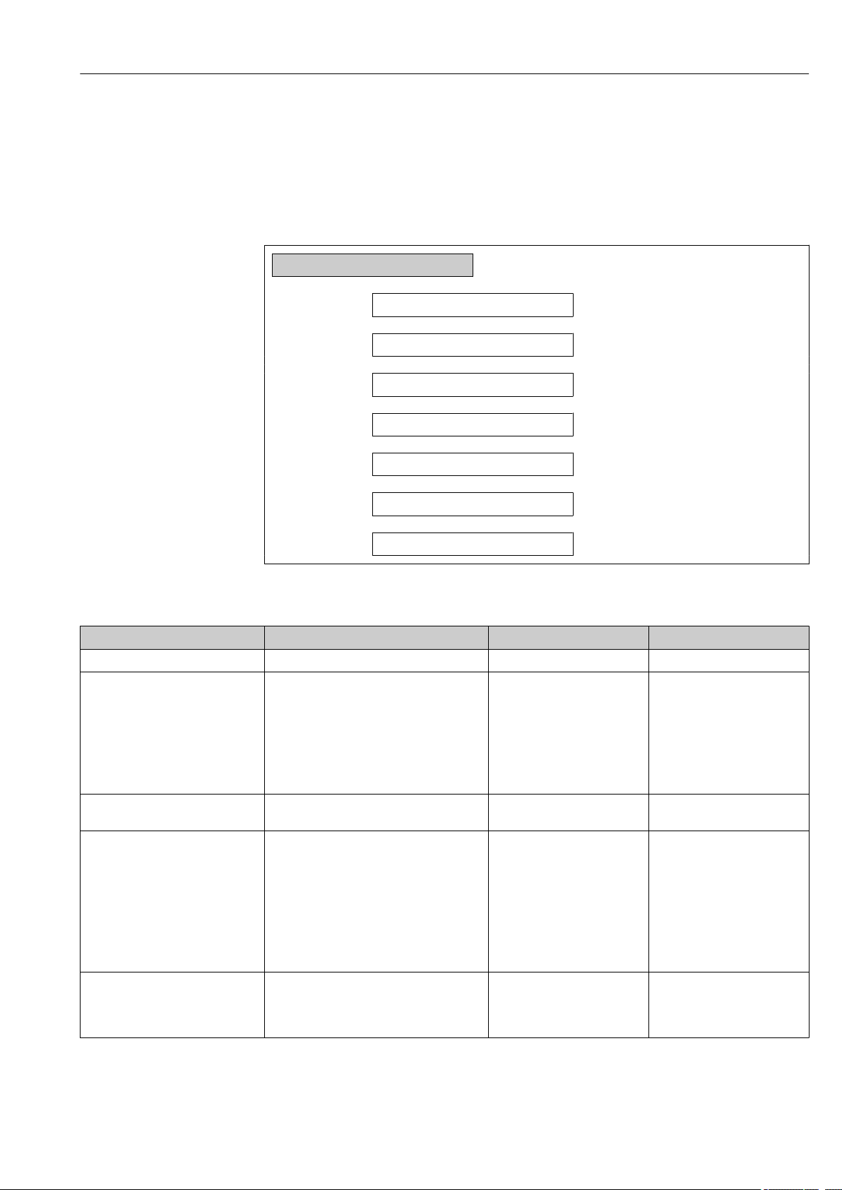
The Communication submenu guides you systematically through all the parameters that
have to be configured for selecting and setting the communication interface.
Navigation
"Setup" menu → Communication
Communication
‣
Bus address
Baudrate
Data transfer mode
Parity
Byte order
Assign diagnostic behavior
Failure mode
Parameter overview with brief description
Parameter Description User entry / Selection Factory setting
Bus address Enter device address. 1 to 247 247
Baudrate Define data transfer speed. • 1200 BAUD
• 2400 BAUD
• 4800 BAUD
• 9600 BAUD
• 19200 BAUD
• 38400 BAUD
• 57600 BAUD
• 115200 BAUD
Data transfer mode Select data transfer mode. • ASCII
• RTU
Parity Select parity bits. Picklist ASCII option:
• 0 = Even option
• 1 = Odd option
Picklist RTU option:
• 0 = Even option
• 1 = Odd option
• 2 = None / 1 stop bit option
• 3 = None / 2 stop bits
option
Byte order Select byte transmission sequence. • 0-1-2-3
• 3-2-1-0
• 1-0-3-2
• 2-3-0-1
19200 BAUD
RTU
Even
1-0-3-2
Endress+Hauser 41
Page 42
Commissioning Dosimag Modbus RS485
Parameter Description User entry / Selection Factory setting
Assign diagnostic behavior Select diagnostic behavior for MODBUS
communication.
Failure mode Select measured value output behavior when
a diagnostic message occurs via Modbus
communication.
1)
NaN
1) Not a Number
• Off
• Alarm or warning
• Warning
• Alarm
• NaN value
• Last valid value
Alarm
NaN value
10.4.6 Low flow cut off
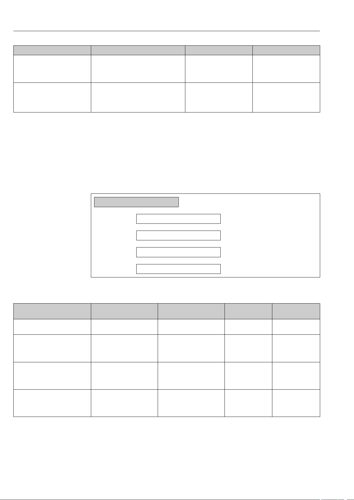
The Low flow cut off submenu contains the parameters that must be set in order to
configure the low flow cut off.
Navigation
"Setup" menu → Low flow cut off
Low flow cut off
‣
Assign process variable
On value low flow cutoff
Off value low flow cutoff
Pressure shock suppression
Parameter overview with brief description
Parameter Prerequisite Description Selection / User
Assign process variable – Select process variable for low
flow cut off.
On value low flow cutoff In the Assign process variable
parameter (→ 42), the
Volume flow option is
selected.
Off value low flow cutoff In the Assign process variable
parameter (→ 42), the
Volume flow option is
selected.
Pressure shock suppression In the Assign process variable
parameter (→ 42), the
Volume flow option is
selected.
Enter on value for low flow cut
off.
Enter off value for low flow cut
off.
Enter time frame for signal
suppression (= active pressure
shock suppression).
entry
• Off
• Volume flow
Signed floating-point
number
0 to 100.0 % 50 %
0 to 100 s 0 s
Volume flow
Depends on country
and nominal
diameter
Factory setting
10.5 Advanced settings
The Advanced setup submenu together with its submenus contains parameters for
specific settings.
42 Endress+Hauser
Page 43
Dosimag Modbus RS485 Commissioning
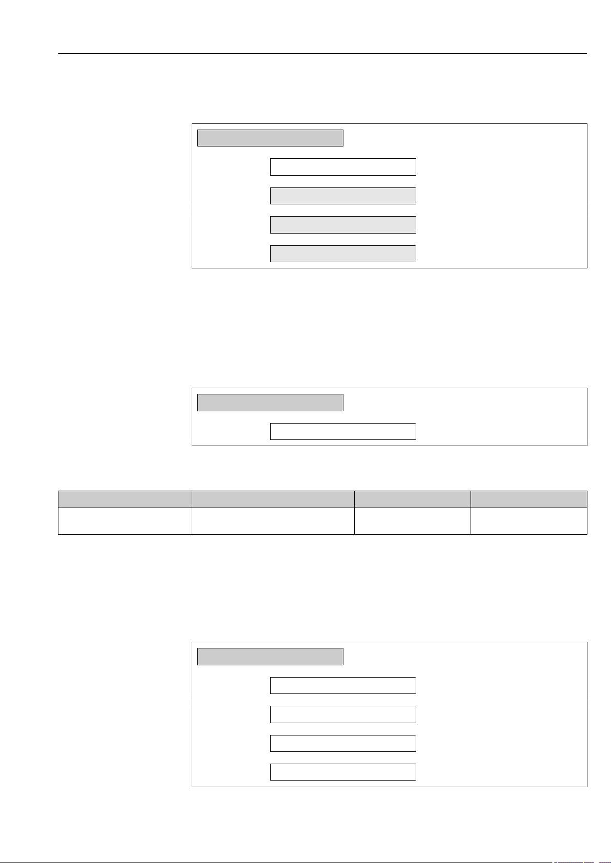
Navigation
"Setup" menu → Advanced setup
Advanced setup
‣
Enter access code
Sensor adjustment
‣
Totalizer 1 to n
‣
Administration
‣
→ 43
→ 43
→ 56
10.5.1 Sensor adjustment
The Sensor adjustment submenu contains parameters that pertain to the functionality of
the sensor.
Navigation
"Setup" menu → Advanced setup → Sensor adjustment
Sensor adjustment
‣
Installation direction
Parameter overview with brief description
Parameter Description Selection Factory setting
Installation direction Set sign of flow direction to match the
direction of the arrow on the sensor.
10.5.2 Configuring the totalizer
The totalizer in question can be configured in the Totalizer 1 to n submenu.
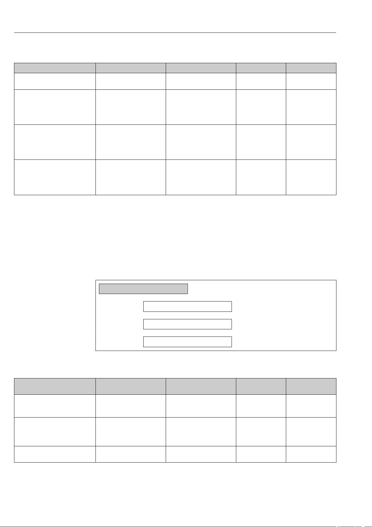
Navigation
"Setup" menu → Advanced setup → Totalizer 1 to n
Totalizer 1 to n
‣
Assign process variable
Volume unit
Totalizer operation mode
Failure mode
• Flow in arrow direction
• Flow against arrow direction
Flow in arrow direction
Endress+Hauser 43
Page 44
Commissioning Dosimag Modbus RS485
Parameter overview with brief description
Parameter Prerequisite Description Selection Factory setting
Assign process variable – Select process variable for
totalizer.
Volume unit The Volume flow option is
selected in the Assign process
variable parameter (→ 44)
of the Totalizer 1 to n
submenu.
Totalizer operation mode In the Assign process variable
parameter (→ 44) of the
Totalizer 1 to n submenu, the
Volume flow option is
selected.
Failure mode In the Assign process variable
parameter (→ 44) of the
Totalizer 1 to n submenu, the
Volume flow option is
selected.
Select volume unit. Unit choose list Depending on
Select totalizer calculation
mode.
Define totalizer behavior in
alarm condition.
• Off
• Volume flow
• Net flow total
• Forward flow total
• Reverse flow total
• Stop
• Actual value
• Last valid value
Volume flow
country:
• ml
• fl oz (us)
Net flow total
Stop
10.6 Simulation
The Simulation submenu enables you to simulate, without a real flow situation, various
process variables in the process and the device alarm mode and to verify downstream
signal chains (switching valves or closed-control loops).
Navigation
"Diagnostics" menu → Simulation
Simulation
‣
Assign simulation process variable
Value process variable
Simulation device alarm
Parameter overview with brief description
Parameter Prerequisite Description Selection / User
Assign simulation process variable – Select a process variable for
the simulation process that is
activated.
Value process variable In the Assign simulation
process variable parameter
(→ 44), the Volume flow
option is selected.
Simulation device alarm – Switch the device alarm on and
Enter the simulation value for
the selected process variable.
off.
entry
• Off
• Volume flow
Depends on the
process variable
selected
• Off
• On
Factory setting
Off
0
Off
44 Endress+Hauser
Page 45

Dosimag Modbus RS485 Operation
11 Operation
11.1 Reading device locking status
Device active write protection: Locking status parameter
Navigation
"Operation" menu → Locking status
Function scope of "Locking status" parameter
Options Description
Temporarily locked Write access to the parameters is temporarily lock due to device-internal
processing (e.g. data upload/download, reset). Once the internal processing has
been completed, the parameters can be changed once again.
Parameter overview with brief description
Parameter Description User interface Factory setting
Locking status Indicates the write protection with the
highest priority that is currently active.
Temporarily locked Temporarily locked
11.2 Reading access authorization status on operating software
Displaying active access authorization: Access status tooling parameter
Navigation
"Operation" menu → Access status tooling
Parameter overview with brief description
Parameter Description User interface Factory setting
Access status tooling Shows the access authorization to the
parameters via the operating tool.
11.3 Reading measured values
With the Measured values submenu, it is possible to read all the measured values.
11.3.1 Process variables
The Process variables submenu contains all the parameters needed to display the current
measured values for every process variable.
• Operator
• Maintenance
Maintenance
Endress+Hauser 45
Page 46
Operation Dosimag Modbus RS485
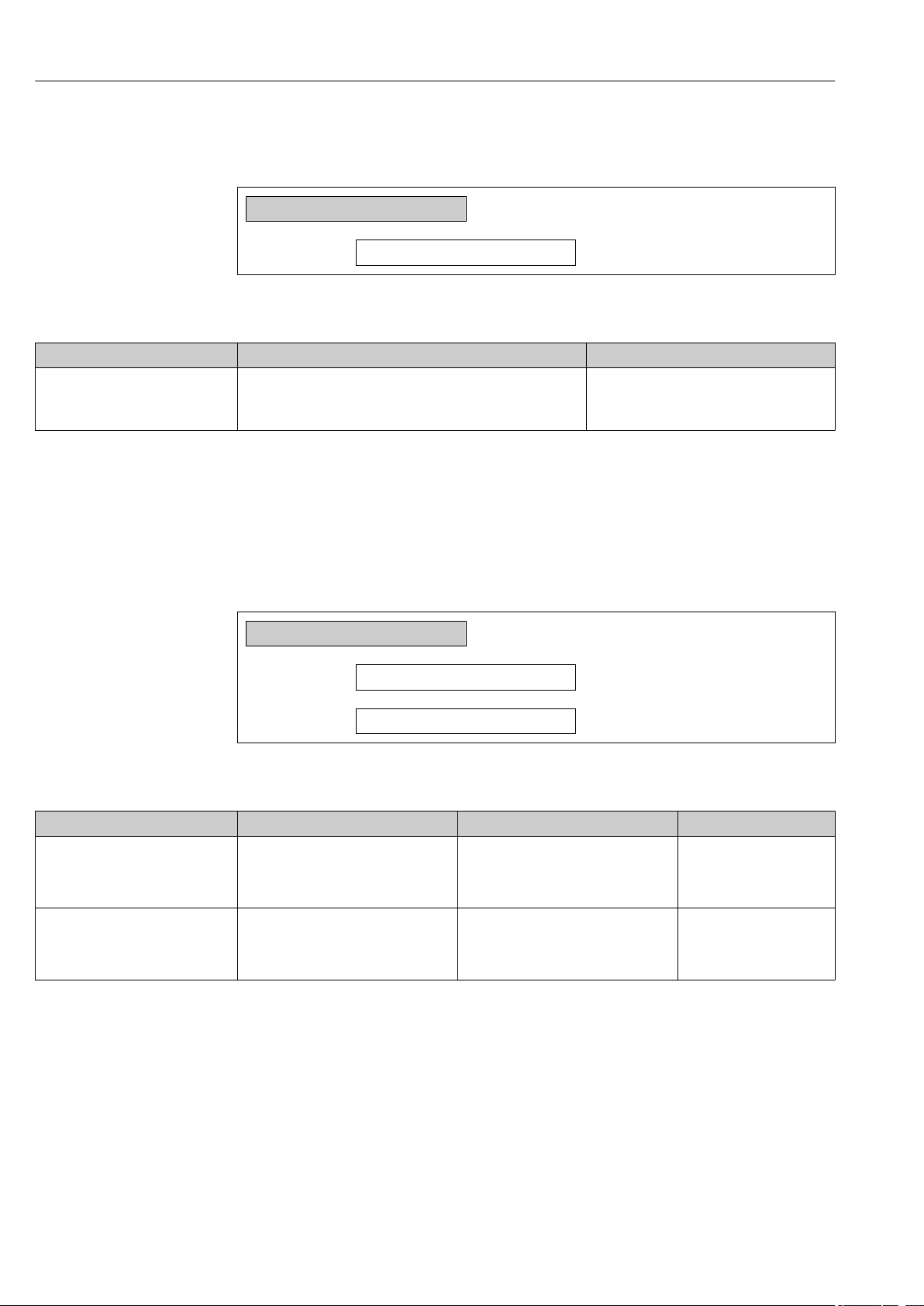
Navigation
"Diagnostics" menu → Measured values → Process variables
Process variables
‣
Volume flow
Parameter overview with brief description
Parameter Description User interface
Volume flow Displays the volume flow currently measured.
Dependency
The unit is taken from the Volume flow unit parameter
Signed floating-point number
11.3.2 Totalizer
The Totalizer submenu contains all the parameters needed to display the current
measured values for every totalizer.
Navigation
"Diagnostics" menu → Measured values → Totalizer
Totalizer
‣
Totalizer value 1 to n
Totalizer overflow 1 to n
Parameter overview with brief description
Parameter Prerequisite Description User interface
Totalizer value In the Assign process variable
parameter (→ 44) of the Totalizer 1
to n submenu, the Volume flow option
is selected.
Totalizer overflow In the Assign process variable
parameter (→ 44) of the Totalizer 1
to n submenu, the Volume flow option
is selected.
Displays the current totalizer counter
value.
Displays the current totalizer overflow. Integer with sign
Signed floating-point
number
11.3.3 Input values
The Input values submenu guides you systematically to the individual input values.
46 Endress+Hauser
Page 47
Dosimag Modbus RS485 Operation
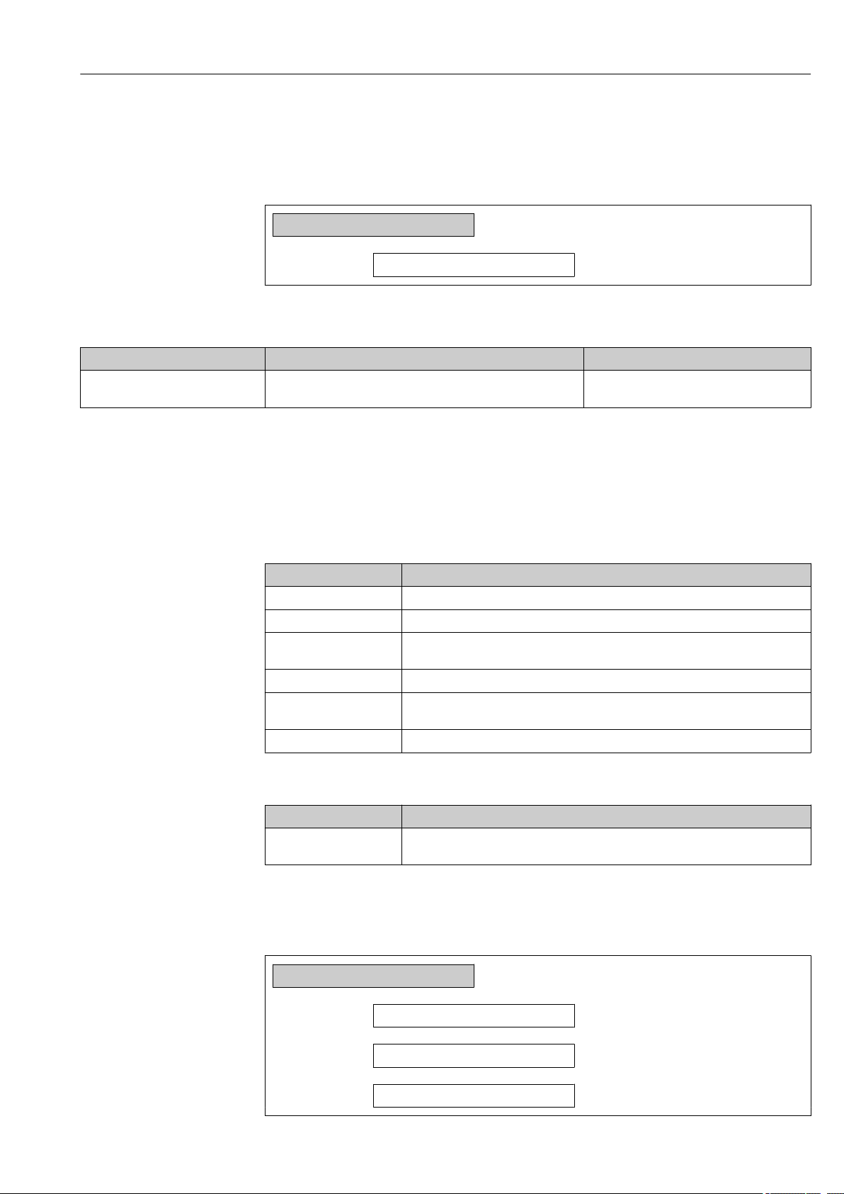
Navigation
"Diagnostics" menu → Measured values → Input values
Structure of the submenu
Input values
‣
Value status input
Parameter overview with brief description
Parameter Description User interface
Value status input Shows the current input signal level. • High
• Low
11.4 Performing a totalizer reset
In the Operation submenu the totalizers are reset:
• Control Totalizer
• Reset all totalizers
Function scope of the "Control Totalizer" parameter
Options Description
Totalize The totalizer is started.
Reset + hold The totaling process is stopped and the totalizer is reset to 0.
Preset + hold The totaling process is stopped and the totalizer is set to its defined start value
from the Preset value parameter.
Reset + totalize The totalizer is reset to 0 and the totaling process is restarted.
Preset + totalize The totalizer is set to the defined start value in the Preset value parameter and the
totaling process is restarted.
Hold Totalizing is stopped.
Function scope of the "Reset all totalizers" parameter
Options Description
Reset + totalize Resets all totalizers to 0 and restarts the totaling process. This deletes all the flow
values previously totalized.
Navigation
"Operation" menu → Totalizer handling
Totalizer handling
‣
Control Totalizer 1 to n
Preset value 1 to n
Reset all totalizers
Endress+Hauser 47
Page 48
Operation Dosimag Modbus RS485
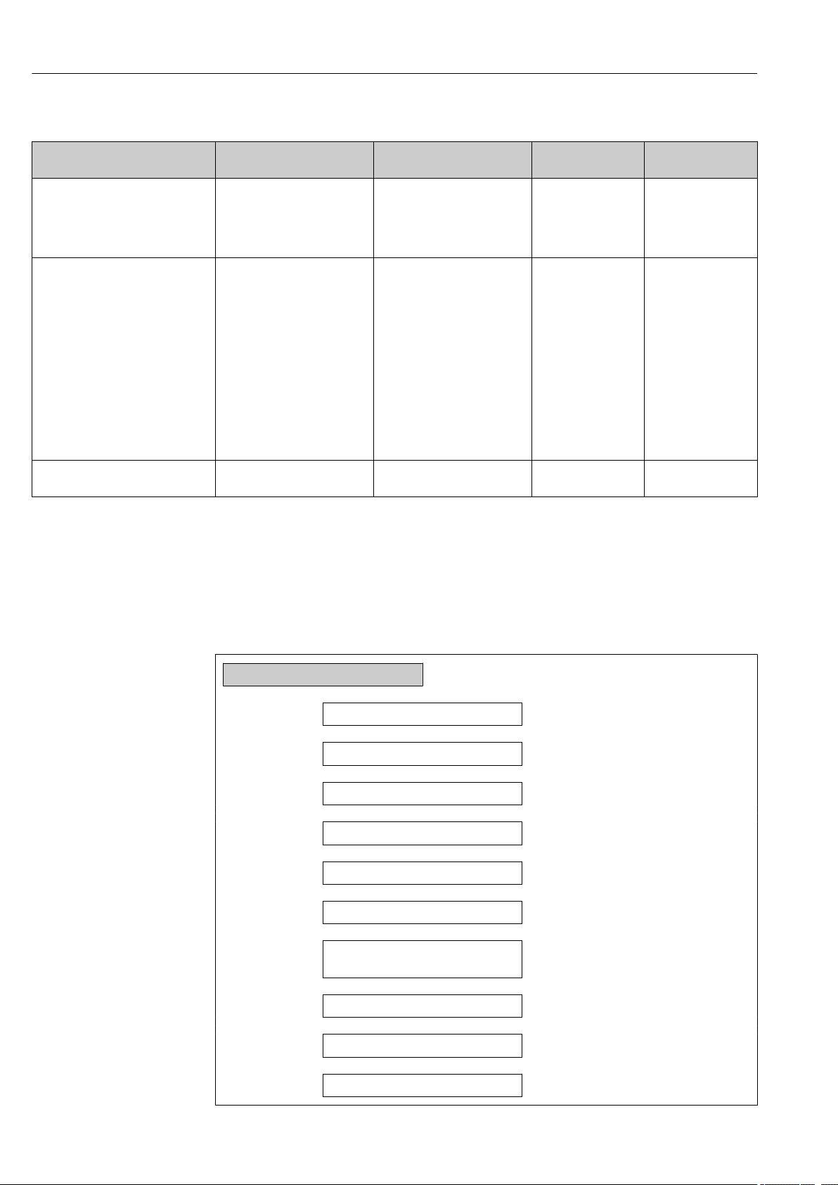
Parameter overview with brief description
Parameter Prerequisite Description Selection / User
Control Totalizer In the Assign process variable
parameter (→ 44) of the
Totalizer 1 to n submenu, the
Volume flow option is
selected.
Preset value In the Assign process variable
parameter (→ 44) of the
Totalizer 1 to n submenu, the
Volume flow option is
selected.
Reset all totalizers – Reset all totalizers to 0 and
Control totalizer value. • Totalize
Specify start value for totalizer.
Dependency
The unit of the selected
process variable is
specified for the totalizer
in the Assign process
variable parameter. If
the following is selected
in the Assign process
variable parameter:
Volume flow option:
Volume flow unit
parameter
start.
11.5 Batching control
entry
• Reset + hold
• Preset + hold
• Reset + totalize
• Preset + totalize
Signed floating-point
number
• Cancel
• Reset + totalize
Factory setting
Totalize
Country-specific:
• 0 m³
• 0 ft³
Cancel
The Batching submenu contains all the parameters required for batching control.
Navigation
"Operation" submenu → Batching
Batching
‣
Batch control
Batch counter
Quantity last batch
Quantity last drip
Current drip correction quantity
Overall batching quantity
Overflow number overall batch.
quantity
Switch output function 1
Switch status 1
Switch output function 2
48 Endress+Hauser
Page 49

Dosimag Modbus RS485 Operation
Switch status 2
Reset overall batching quantity
Parameter overview with brief description
Parameter Description Selection / User interface Factory setting
Batch control Switch the batch on and off. • Start
• Stop
Batch counter Shows number of passed batch procedures. Positive integer –
Quantity last batch Shows total quantity of last batch.
Dependency
The unit is taken from: Batch unit
parameter
Quantity last drip Shows drip quantity of last batch.
Dependency
The unit is taken from: Batch unit
parameter
Current drip correction quantity Shows the drip correction quantity of current
batch.
Dependency
The unit is taken from: Batch unit
parameter
Overall batching quantity Shows the total quantity of all passed batch
procedures of current profile.
Dependency
The unit is taken from: Batch unit
parameter
Overflow number overall batch.
quantity
Switch output function 1 to n Select function for the switch output. • Close
Switch status 1 to n Display the current status of the switch
Reset overall batching quantity Reset the total quantity of all passed batch
Shows how often an overflow of the overall
batching quantity has occured.
output.
procedures to 0.
Signed floating-point number –
Signed floating-point number –
Signed floating-point number –
Signed floating-point number –
–32 000.0 to 32 000.0 –
• Open
• Batching
• Closed
• Open
• Reset
• Cancel
Stop
• Batching (Switch output
function 1)
• Open (Switch output
function 2)
–
Cancel
Endress+Hauser 49
Page 50

Diagnostics and troubleshooting Dosimag Modbus RS485
12 Diagnostics and troubleshooting
12.1 General troubleshooting
For access
Problem Possible causes Remedy
No write access to parameters Current user role has limited access
authorization
No connection via Modbus RS485 Device plug connected incorrectly Check the pin assignment of the
No connection via Modbus RS485 Modbus RS485 cable incorrectly
terminated
No connection via Modbus RS485 Incorrect settings for the
communication interface
No connection via service adapter Incorrect configuration of USB
interface on PC or driver not
installed correctly.
Check access authorization status .
device plug .
Check the terminating resistor .
Check the Modbus RS485
configuration .
Observe the documentation for the
Commubox.
FXA291: Document
"Technical Information"
TI00405C
12.2 Diagnostic information in FieldCare
12.2.1 Diagnostic options
Any faults detected by the measuring device are displayed on the home page of the
operating tool once the connection has been established.
50 Endress+Hauser
Page 51
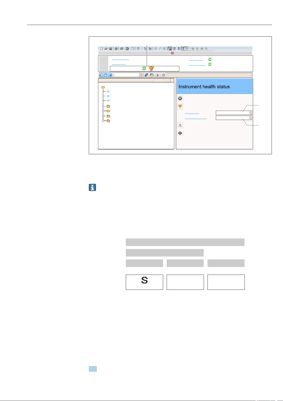
Dosimag Modbus RS485 Diagnostics and troubleshooting
Xxxxxx/…/…/
Xxxxxx
P
P
P
+
+
+
+
Diagnostics 1:
Remedy information:
Failure (F)
Function check (C)
Out of spezification (S)
Maintenance required (M)
C485 Simulation measured vari...
Deactivate Simulation (Service...
Diagnostics 1: C485 Simu...
Remedy information: Deactivate...
Access status tooling: Mainenance
Operation
Setup
Diagnostics
Expert
Function check (C)Status signal:
Device tag:
Device name:
Mass flow:
Volume flow:
Xxxxxxx
12.34
kg/h
12.34
m /h³
Xxxxxxx
1
2
3
A0021799-EN
1 Status area with status signal
2 Diagnostic information → 51
3 Remedy information with Service ID
Endress+Hauser 51
Furthermore, diagnostic events that have occurred can be viewed in the Diagnostics
menu:
• Via parameter
• Via submenu → 55
Diagnostic information
The fault can be identified using the diagnostic information. The short text helps you by
providing information about the fault.
Diagnostic information
Diagnostic code
Status signal Diagnostic number Short text
↓ ↓ ↓
Example
A0013958
12.2.2 Calling up remedy information
Remedy information is provided for every diagnostic event to ensure that problems can be
842 Process limit
3-digit number
rectified quickly:
• On the home page
Remedy information is displayed in a separate field below the diagnostics information.
• In the Diagnostics menu
Remedy information can be called up in the working area of the user interface.
The user is in the Diagnostics menu.
1. Call up the desired parameter.
Page 52

Diagnostics and troubleshooting Dosimag Modbus RS485
2. On the right in the working area, mouse over the parameter.
A tool tip with remedy information for the diagnostic event appears.
12.3 Diagnostic information via communication interface
12.3.1 Reading out diagnostic information
Diagnostic information can be read out via Modbus RS485 register addresses.
• Via register address 6821 (data type = string): diagnosis code, e.g. F270
• Via register address 6859 (data type = integer): diagnosis number, e.g. 270
For an overview of diagnostic events with diagnosis number and diagnosis code
→ 53
12.3.2 Configuring error response mode
Error response mode for Modbus RS485 communication can be configured in the
Communication submenu using 2 parameters.
Navigation path
"Setup" menu → Communication
Parameter overview with brief description
Parameter Description Options Factory setting
Assign diagnostic
behavior
Failure mode Select measured value
Select diagnostic behavior
for MODBUS
communication.
output behavior when a
diagnostic message occurs
via Modbus
communication.
This parameter
operates in
accordance with the
option selected in
the Assign
diagnostic
behavior
parameter.
• Off
• Alarm or warning
• Warning
• Alarm
• NaN value
• Last valid value
NaN º not a number
Alarm
NaN value
12.4 Adapting the diagnostic information
12.4.1 Adapting the diagnostic behavior
Each item of diagnostic information is assigned a specific diagnostic behavior at the
factory. The user can change this assignment for certain diagnostic information in the
Diagnostic behavior submenu.
Expert → System → Diagnostic handling → Diagnostic behavior
52 Endress+Hauser
Page 53
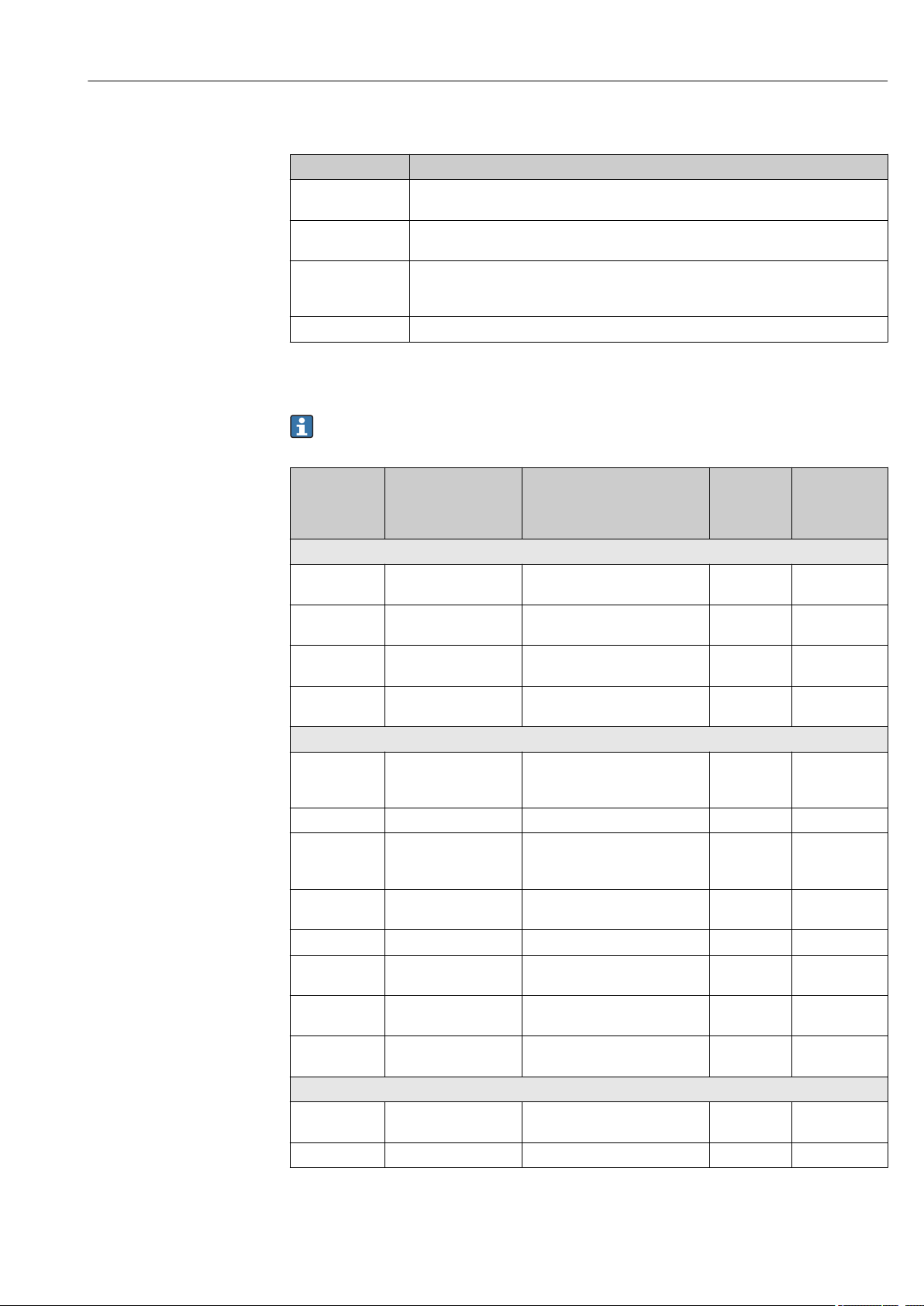
Dosimag Modbus RS485 Diagnostics and troubleshooting
You can assign the following options to the diagnostic number as the diagnostic behavior:
Options Description
Alarm Measurement is interrupted. Measured value output via Modbus RS485 and totalizers
assume the defined alarm condition. A diagnostic message is generated.
Warning Measurement is resumed. Measured value output via Modbus RS485 and totalizers are
not affected. A diagnostic message is generated.
Logbook entry only The device continues to measure. The diagnostic message is entered in the Event
logbook (events list) submenu only and is not displayed in alternation with the measured
value display.
Off The diagnostic event is ignored, and no diagnostic message is generated or entered.
12.5 Overview of diagnostic information
In the case of some items of diagnostic information, the status signal and the
diagnostic behavior can be changed. Change the diagnostic information → 52
Diagnostic
number
Diagnostic of sensor
004 Sensor 1. Change sensor
062 Sensor connection 1. Check sensor connections
082 Data storage 1. Check module connections
083 Memory content 1. Restart device
Diagnostic of electronic
242 Software incompatible 1. Check software
270 Main electronic failure Change main electronic module F Alarm
271 Main electronic failure 1. Restart device
272 Main electronic failure 1. Restart device
273 Main electronic failure Change electronic F Alarm
281 Electronic initialization Firmware update active, please
311 Electronic failure 1. Reset device
322 Electronic drift 1. Perform verification manually
Diagnostic of configuration
410 Data transfer 1. Check connection
411 Up-/download active Up-/download active, please wait C Warning
Short text Remedy instructions Status signal
[from the
factory]
S Alarm
2. Contact service
F Alarm
2. Contact service
F Alarm
2. Contact service
F Alarm
2. Contact service
F Alarm
2. Flash or change main
electronics module
F Alarm
2. Change main electronic
module
F Alarm
2. Contact service
F Alarm
wait!
F Alarm
2. Contact service
S Warning
2. Change electronic
F Alarm
2. Retry data transfer
Diagnostic
behavior
[from the
factory]
Endress+Hauser 53
Page 54
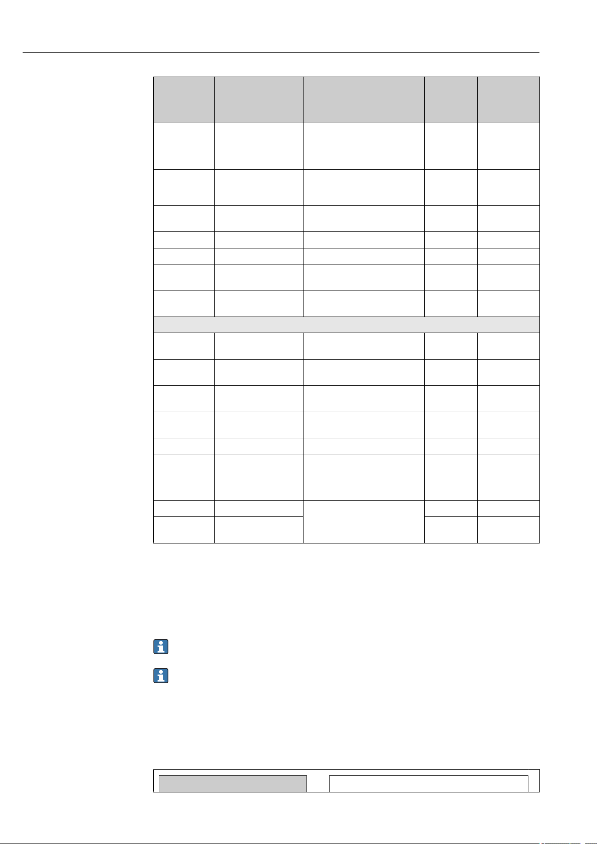
Diagnostics and troubleshooting Dosimag Modbus RS485
Diagnostic
number
438 Dataset 1. Check data set file
442 Frequency output 1 to n 1. Check process
443 Pulse output 1 to n 1. Check process
453 Flow override Deactivate flow override C Warning
484 Simulation failure mode Deactivate simulation C Alarm
485 Simulation measured
500 Electrode difference
Diagnostic of process
832 Electronic temperature
833 Electronic temperature
834 Process temperature
835 Process temperature
937 EMC interference Change main electronic module S Warning
938 EMC interference 1. Check ambient conditions
991 Batch time exceeded Check process conditions F Warning
991 Maximum flow rate
Short text Remedy instructions Status signal
2. Check device configuration
3. Up- and download new
configuration
2. Check frequency output
settings
2. Check pulse output settings
Deactivate simulation C Warning
variable
1. Check process cond.
voltage too high
too high
too low
too high
too low
exceeded
2. Increase system pressure
Reduce ambient temperature S Warning
Increase ambient temperature S Warning
Reduce process temperature S Warning
Increase process temperature S Warning
regarding EMC influence
2. Change main electronic
module
[from the
factory]
M Warning
S Warning
S Warning
F Alarm
F Alarm
F Warning
Diagnostic
behavior
[from the
factory]
1)
1)
1)
1)
1)
1)
1)
1)
1)
1) Diagnostic behavior can be changed.
12.6 Pending diagnostic events
The Diagnostics menu provides the option of displaying the current and previous
diagnostic event separately.
To call up the measures to rectify a diagnostic event:
Via the DeviceCare and FieldCare operating tool→ 51
Other pending diagnostic events can be displayed in the Diagnostic list submenu
→ 55
Navigation
"Diagnostics" menu
Structure of the submenu
Diagnostics
54 Endress+Hauser
→
Actual diagnostics
Page 55
Dosimag Modbus RS485 Diagnostics and troubleshooting
Previous diagnostics
Parameter overview with brief description
Parameter Prerequisite Description User interface
Actual diagnostics A diagnostic event has occurred. Shows the current occured diagnostic
event along with its diagnostic
information.
If two or more messages occur
simultaneously, the message with
the highest priority is shown on
the display.
Previous diagnostics Two diagnostic events have already
occurred.
Shows the diagnostic event that
occurred prior to the current diagnostic
event along with its diagnostic
information.
Symbol for diagnostic
behavior, diagnostic code
and short message.
Symbol for diagnostic
behavior, diagnostic code
and short message.
12.7 Diagnostic list
In the Diagnostic list submenu, up to 5 currently pending diagnostic events can be
displayed along with the related diagnostic information. If more than 5 diagnostic events
are pending, the events with the highest priority are shown on the display.
Navigation path
Diagnostics menu → Diagnostic list submenu
To call up the measures to rectify a diagnostic event:
Via "FieldCare" operating tool → 51
12.8 Event logbook
12.8.1 Event history
To call up the measures to rectify a diagnostic event:
Via "FieldCare" operating tool → 51
For filtering the displayed event messages → 55
12.8.2 Filtering the event logbook
Using the Filter options parameter, you can define which category of event messages is
displayed in the Events list submenu.
Navigation path
"Diagnostics" menu → Event logbook → Filter options
Filter categories
• All
• Failure (F)
• Function check (C)
• Out of specification (S)
• Maintenance required (M)
• Information (I)
Endress+Hauser 55
Page 56
Diagnostics and troubleshooting Dosimag Modbus RS485
12.8.3 Overview of information events
Unlike a diagnostic event, an information event is displayed in the event logbook only and
not in the diagnostic list.
Info number Info name
I1000 --------(Device ok)
I1089 Power on
I1090 Configuration reset
I1091 Configuration changed
I1110 Write protection switch changed
I1151 History reset
12.9 Resetting the measuring device
The device can be reset in theAdministration submenu.
Navigation
"Expert" menu → System → Administration
Administration
‣
Device reset
Parameter overview with brief description
Parameter Description Selection Factory setting
Device reset Reset the device configuration - either
entirely or in part - to a defined state.
12.10 Device information
The Device information submenu contains all parameters that display different
information for device identification.
Navigation
"Diagnostics" menu → Device information
Device information
‣
• Cancel
• To delivery settings
• Restart device
Cancel
Device tag
Serial number
Firmware version
Device name
56 Endress+Hauser
Page 57

Dosimag Modbus RS485 Diagnostics and troubleshooting
Order code
Extended order code 1
Extended order code 2
Extended order code 3
ENP version
Parameter overview with brief description
Parameter Description User interface Factory setting
Device tag Display the name for the measuring point. Max. 32 characters such as
letters, numbers or special
characters (e.g. @, %, /)
Serial number Shows the serial number of the measuring
device.
Firmware version Shows the device firmware version installed. Character string with the
Device name Shows the name of the transmitter.
The name can be found on the
nameplate of the transmitter.
Order code Shows the device order code.
It can be found in the "Order code" field
on the nameplate.
Extended order code 1 Shows the 1st part of the extended order
code.
It can be found in the "Ext. ord. cd."
field on the nameplate.
Extended order code 2 Shows the 2nd part of the extended order
code.
The extended order code can also be
found on the nameplate of the sensor
and transmitter in the "Ext. ord. cd."
field.
Extended order code 3 Shows the 3rd part of the extended order
code.
The extended order code can also be
found on the nameplate of the sensor
and transmitter in the "Ext. ord. cd."
field.
ENP version Shows the version of the electronic
nameplate (ENP).
A maximum of 11-digit
character string comprising
letters and numbers.
following format:
xx.yy.zz
Dosimag –
Character string composed of
letters, numbers and certain
punctuation marks (e.g. /).
Character string –
Character string –
Character string –
Dosimag
–
03.00
–
2.02.00
Endress+Hauser 57
Page 58

Diagnostics and troubleshooting Dosimag Modbus RS485
12.11 Firmware history
Release
date
09.2015 03.00.zz Option A No change in
08.2014 03.00.zz Option A • Original firmware
Firmware
version
Order code
for
"Firmware
version"
Firmware
changes
firmware
• Can be operated via
FieldCare and
DeviceCare
Documentation
type
Operating
Instructions
Operating
Instructions
Documentation
BA01321D/06/EN/02.15
BA01321D/06/EN/01.14
For the compatibility of the firmware version with the previous version, the installed
device description files and operating tools, observe the information about the device
in the "Manufacturer's information" document.
The manufacturer's information is available:
• In the Downloads area of the Endress+Hauser web site: www.endress.com →
Downloads
• Specify the following details:
– Product root: e.g. 5RH
– Text search: Manufacturer's information
– Media type: Documentation – Technical Documentation
58 Endress+Hauser
Page 59

Dosimag Modbus RS485 Maintenance
13 Maintenance
13.1 Maintenance tasks
No special maintenance work is required.
13.1.1 Exterior cleaning
When cleaning the exterior of measuring devices, always use cleaning agents that do not
attack the surface of the housing or the seals.
13.1.2 Interior cleaning
Observe the following points for CIP and SIP cleaning:
• Use only cleaning agents to which the process-wetted materials are adequately resistant.
• Observe the maximum permitted medium temperature for the measuring device .
13.1.3 Replacing seals
The sensor's seals (particularly aseptic molded seals) must be replaced periodically.
The interval between changes depends on the frequency of the cleaning cycles, the
cleaning temperature and the medium temperature.
Replacement seals (accessory part) → 62
13.2 Measuring and test equipment
Endress+Hauser offers a wide variety of measuring and test equipment, such as W@M or
device tests.
Your Endress+Hauser Sales Center can provide detailed information on the services.
For a list of some of the measuring and test equipment, refer to the "Accessories"
chapter of the "Technical Information" document for the device.
13.3 Endress+Hauser services
Endress+Hauser offers a wide variety of services for maintenance such as recalibration,
maintenance service or device tests.
Your Endress+Hauser Sales Center can provide detailed information on the services.
Endress+Hauser 59
Page 60

Repair Dosimag Modbus RS485
14 Repair
14.1 General notes
Repair and conversion concept
The Endress+Hauser repair and conversion concept provides for the following:
• The measuring device cannot be converted.
• If the measuring device is defective, the entire device is replaced.
• It is possible to replace seals.
Information on replacing wear parts (seals)
Please note the following when replacing wear parts:
• Use only original Endress+Hauser spare parts.
• Replace the part according to the Installation Instructions.
• Observe the applicable standards, federal/national regulations, Ex documentation (XA)
and certificates.
• Document every repair and each conversion and enter them into the W@M life cycle
management database.
14.2 Spare parts
W@M Device Viewer (www.endress.com/deviceviewer):
All the spare parts for the measuring device, along with the order code, are listed here and
can be ordered. If available, users can also download the associated Installation
Instructions.
Measuring device serial number:
• Is located on the nameplate of the device.
• Can be read out via the Serial number parameter in the Device information
submenu → 56.
14.3 Endress+Hauser services
Endress+Hauser offers a wide range of services.
Your Endress+Hauser Sales Center can provide detailed information on the services.
14.4 Return
The measuring device must be returned if it is need of repair or a factory calibration, or if
the wrong measuring device has been delivered or ordered. Legal specifications require
Endress+Hauser, as an ISO-certified company, to follow certain procedures when handling
products that are in contact with the medium.
To ensure safe, swift and professional device returns, please refer to the procedure and
conditions for returning devices provided on the Endress+Hauser website at
http://www.endress.com/support/return-material
14.5 Disposal
14.5.1 Removing the measuring device
1. Switch off the device.
60 Endress+Hauser
Page 61

Dosimag Modbus RS485 Repair
2.
WARNING
L
Danger to persons from process conditions.
Beware of hazardous process conditions such as pressure in the measuring device,
‣
high temperatures or aggressive fluids.
Carry out the mounting and connection steps from the chapters "Mounting the
measuring device" and "Connecting the measuring device" in the logically reverse
sequence. Observe the safety instructions.
14.5.2 Disposing of the measuring device
WARNING
L
Danger to personnel and environment from fluids that are hazardous to health.
Ensure that the measuring device and all cavities are free of fluid residues that are
‣
hazardous to health or the environment, e.g. substances that have permeated into
crevices or diffused through plastic.
Observe the following notes during disposal:
• Observe valid federal/national regulations.
• Ensure proper separation and reuse of the device components.
Endress+Hauser 61
Page 62

Accessories Dosimag Modbus RS485
15 Accessories
Various accessories, which can be ordered with the device or subsequently from Endress
+Hauser, are available for the device. Detailed information on the order code in question is
available from your local Endress+Hauser sales center or on the product page of the
Endress+Hauser website: www.endress.com.
15.1 Device-specific accessories
15.1.1 For the sensor
Accessories Description Order code
Seal set For regular replacement of the seals on the
process connections.
Housing seal To seal the transmitter 50102857
Mounting set Consists of:
• 2 process connections
• Screws
• Seals
DK5G**-***
DKH**-****
15.2 Communication-specific accessories
Accessories Description
FieldCare FDT-based plant asset management tool from Endress+Hauser.
It can configure all smart field units in your system and helps you manage them. By
using the status information, it is also a simple but effective way of checking their
status and condition.
For details, see Operating Instructions BA00027S and BA00059S
DeviceCare Tool for connecting and configuring Endress+Hauser field devices.
For details, see Innovation brochure IN01047S
Commubox FXA291 Connects Endress+Hauser field devices with a CDI interface (= Endress+Hauser
Common Data Interface) and the USB port of a computer or laptop.
For details, see the "Technical Information" document TI405C/07
Adapter connection Adapter connections for installation on other electrical connections:
• Adapter FXA291 (order number: 71035809)
• Adapter RSE8 (order number: 50107169)
RSE8 connection jack, 8-pin adapter (RSE8), 24 V DC, pulse, status
• Adapter RSE5 (order number: 50107168 )
RSE8 connection jack, 5-pin adapter (RSE5), 24 V DC, pulse, status
• Adapter RSE4 (order number: 50107167)
RSE8 connection jack, 4-pin adapter (RSE4), 24 V DC, pulse
Connecting cable RSE8 Cable RKWTN8-56/5 P92, length: 5 m
(Order number: 50107895)
62 Endress+Hauser
Page 63

Dosimag Modbus RS485 Accessories
15.3 Service-specific accessories
Accessories Description
Applicator Software for selecting and sizing Endress+Hauser measuring devices:
• Calculation of all data required to determine the optimum flowmeter: e.g.
nominal diameter, pressure loss, accuracy or process connections.
• Graphic illustration of the calculation results
Administration, documentation and access to all project-related data and
parameters throughout the entire life cycle of a project.
Applicator is available:
• Via the Internet: https://wapps.endress.com/applicator
• On CD-ROM for local PC installation.
W@M Life cycle management for your plant
W@M supports you with a wide range of software applications over the entire
process: from planning and procurement, to the installation, commissioning and
operation of the measuring devices. All the relevant information is available for
every measuring device over time entire life cycle, such as the Device status, spare
parts, device-specific documentation.
The application already contains the data of your Endress+Hauser device. Endress
+Hauser also takes care of maintaining and updating the data records.
W@M is available:
• Via the Internet: www.endress.com/lifecyclemanagement
• On CD-ROM for local PC installation.
FieldCare FDT-based plant asset management tool from Endress+Hauser.
It can configure all smart field units in your system and helps you manage them. By
using the status information, it is also a simple but effective way of checking their
status and condition.
For details, see Operating Instructions BA00027S and BA00059S
DeviceCare Tool for connecting and configuring Endress+Hauser field devices.
For details, see Innovation brochure IN01047S
Commubox FXA291 Connects Endress+Hauser field devices with a CDI interface (= Endress+Hauser
Common Data Interface) and the USB port of a computer or laptop.
For details, see "Technical Information" TI00405C
Endress+Hauser 63
Page 64

Technical data Dosimag Modbus RS485
16 Technical data
16.1 Application
Depending on the version ordered, the measuring device can also measure potentially
explosive, flammable, poisonous and oxidizing media.
To ensure that the device remains in proper operating condition for its service life, use the
measuring device only for media against which the process-wetted materials are
sufficiently resistant.
16.2 Function and system design
Measuring principle Electromagnetic flow measurement on the basis of Faraday's law of magnetic induction.
Measuring system The device consists of a transmitter and a sensor.
The device is available as a compact version:
The transmitter and sensor form a mechanical unit.
For information on the structure of the device → 11→ 11
16.3 Input
Measured variable Direct measured variables
Volume flow (proportional to induced voltage)
Measuring range Typically v = 0.01 to 10 m/s (0.03 to 33 ft/s) with specified accuracy
Flow characteristic values in SI units
Nominal diameter
[mm] [l/s] [ml] [ml/s]
4 0.14 0.005 0.5
8 0.5 0.02 2
1)
15K
15 1.66 0.1 7
25 5 0.2 16
1) Conical version (corresponds to DN 12)
Recommended
flow
Max. full scale value Pulse value
1.2 0.1 7
Factory settings
Low flow cut off
(v ~ 0.04 m/s)
64 Endress+Hauser
Page 65

Dosimag Modbus RS485 Technical data
Flow characteristic values in US units
Nominal diameter
[in] [gal/s] [oz fl] [oz fl/s]
⁵⁄₃₂ 0.035 0.0002 0.02
⁵⁄₁₆ 0.13 0.001 0.08
½K
½ 0.44 0.004 0.25
1) Conical version (corresponds to DN 12)
Recommended measuring range
"Flow limit" section → 70
Operable flow range Over 1000 : 1
Input signal Status input
The batching process is controlled by the automation system via the device's status input.
Recommended
flow
Max. full scale value Pulse value
1)
1 1.33 0.007 0.53
0.32 0.004 0.25
Factory settings
Low flow cut off
(v ~ 0.13 ft/s)
Maximum input values • DC 30 V
Response time Adjustable: 10 to 200 ms
Input signal level • Low level: 0 to 1.5 V
Assignable functions • Off
16.4 Output
Output signal Modbus RS485
Physical interface In accordance with EIA/TIA-485-A standard
Switch output (batch: valve control)
Depending on the device version, the device has one or two switch outputs.
• 6 mA
• High level: 3 to 30 V
• Start batching process
• Start and stop batching process
• Reset totalizers 1-3 separately
• Reset all totalizers
• Flow override
Switch output
Version Active, open emitter
Maximum input values • DC 30 V
• 500 mA
Switching behavior Binary, conductive or non-conductive
Endress+Hauser 65
Page 66

Technical data Dosimag Modbus RS485
Number of switching
cycles
Assignable functions • Open
Unlimited
• Closed
• Batching
Signal on alarm Depending on the interface, failure information is displayed as follows:
Modbus RS485
Failure mode Choose from:
• NaN value instead of current value
• Last valid value
Low flow cut off The switch points for low flow cut off are user-selectable.
Galvanic isolation • Device version: Modbus RS485, 1 switch output (batch), 1 status input
(Order code for "Output, input": option 4)
Switch outputs (batch) and status input on supply potential
• Device version: Modbus RS485, 2 switch outputs (batch), 1 status input
(Order code for "Output, input", option 5:)
– Switch outputs (batch) on supply potential.
– Status input, galvanically isolated.
Protocol-specific data Modbus RS485
Protocol Modbus Applications Protocol Specification V1.1
Device type Slave
Slave address range 1 to 247
Broadcast address range 0
Function codes • 03: Read holding register
Broadcast messages Supported by the following function codes:
Supported baud rate • 1 200 BAUD
Data transfer mode • ASCII
Data access Each device parameter can be accessed via Modbus RS485.
• 04: Read input register
• 06: Write single registers
• 08: Diagnostics
• 16: Write multiple registers
• 23: Read/write multiple registers
• 43: Read device identification
• 06: Write single registers
• 16: Write multiple registers
• 23: Read/write multiple registers
• 2 400 BAUD
• 4 800 BAUD
• 9 600 BAUD
• 19 200 BAUD
• 38 400 BAUD
• 57 600 BAUD
• 115 200 BAUD
• RTU
For Modbus register information → 74
66 Endress+Hauser
Page 67
Dosimag Modbus RS485 Technical data
16.5 Power supply
Terminal assignment → 24
Pin assignment, device plug → 25
Supply voltage DC 24 V (nominal voltage: DC 20 to 30 V)
• The power unit must be tested to ensure that it meets safety requirements (e.g.
PELV, SELV).
• The supply voltage must not exceed a maximum short-circuit current of 50 A.
Power consumption 4.5 W
Current consumption
Order code for "Output, input":
Option 4: Modbus RS485, 1 switch output (batch), 1 status input 225 mA + 500 mA
Option 5: Modbus RS485, 2 switch outputs (batch), 1 status input 225 mA + 1 000 mA
Option 6: Modbus RS485 (custody transfer mode) 225 mA
1) Additional 500 mA per switch output (batch) used.
Switch-on current: max. 1 A (< 8 ms)
Power supply failure • Totalizers stop at the last value measured.
• Error messages (incl. total operated hours) are stored.
Electrical connection → 28
Potential equalization Requirements
No potential matching is needed for grounded steel lines.
For devices intended for use in hazardous locations, please observe the guidelines in
the Ex documentation (XA).
Maximum
Power consumption
1)
1)
Cable specification
→ 24
16.6 Performance characteristics
Reference operating conditions
Endress+Hauser 67
In accordance with DIN EN 29104
• Medium temperature: +28 ± 2 °C (+82 ± 4 °F)
• Ambient temperature: +22 ± 2 °C (+72 ± 4 °F)
• Warm-up period:30 min
Page 68
Technical data Dosimag Modbus RS485
Installation
• Inlet run > 10 × DN
• Outlet run > 5 × DN
• Sensor and transmitter grounded.
• The sensor is centered in the pipe.
Maximum measured error Error limits under reference operating conditions
o.r. = of reading
Volume flow
• ±0.25 % o.r. ± 1 to 4 m/s (3.3 to 13 ft/s) or
• ±0.5 % o.r. ± 1 mm/s (0.04 in/s) or
• ±5 % o.r.
Fluctuations in the supply voltage do not have any effect within the specified range.
Repeatability o.r. = of reading
DN 25 (500 ml/s), DN 15 (200 ml/s), DN 8 (50 ml/s), DN 4 (10 ml/s); 400 μS/cm
Ambient temperature range
Batch time ta [s] Relative standard deviation in relation to the batched volume [%]
1.5 s < ta < 3 s 0.4
3 s < ta < 5 s 0.2
5 s < t
a
0.1
DN 15K (200 ml/s); 400 μS/cm
Batch time ta [s] Relative standard deviation in relation to the batched volume [%]
1.5 s < ta < 3 s 0.25
3 s < ta < 5 s 0.12
5 s < t
a
0.08
16.7 Installation
"Mounting requirements"
16.8 Environment
Temperature tables
Observe the interdependencies between the permitted ambient and fluid
temperatures when operating the device in hazardous areas.
For detailed information on the temperature tables, see the separate document
entitled "Safety Instructions" (XA) for the device.
Storage temperature The storage temperature corresponds to the ambient temperature range of the transmitter
and sensor.
68 Endress+Hauser
Page 69
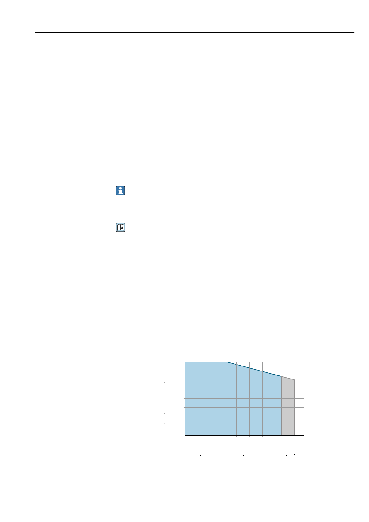
Dosimag Modbus RS485 Technical data
0
-20
20
40
60
[°F] T [°C]
A
140
120
80
60
100
0
40
20
0-20 40 80 120
80 160
240
320
0
160
T
M
130
266
302
150
[°F]
[°C]
• Protect the measuring device against direct sunlight during storage in order to avoid
unacceptably high surface temperatures.
• Select a storage location where moisture cannot collect in the measuring device as
fungus or bacteria infestation can damage the liner.
• If protection caps or protective covers are mounted these should never be removed
before installing the measuring device.
Degree of protection As standard: IP67, type 4X enclosure
Shock resistance Acceleration up to 2 g based on IEC 60068-2-6
Vibration resistance Acceleration up to 2 g based on IEC 60068-2-6
Interior cleaning • Cleaning in place (CIP)
• Sterilization in place (SIP)
Observe the maximum medium temperatures → 69
Electromagnetic compatibility (EMC)
According to IEC/EN 61326
For details, refer to the Declaration of Conformity.
16.9 Process
Medium temperature range Sensor
–20 to +130 °C (–4 to +266 °F)
Cleaning
+150 °C (+302 °F) / 60 min for CIP and SIP processes
Seals
• EPDM: –20 to +130 °C (–4 to +266 °F) (max. +150 °C (302 °F) for cleaning
• Silicon:–20 to +130 °C (–4 to +266 °F)
• Viton:0 to +150 °C (+32 to +302 °F)
Endress+Hauser 69
A0004805
Page 70
Technical data Dosimag Modbus RS485
TAAmbient temperature
TMMedium temperature
Light-gray area: standard fluid temperature range
Dark-gray area: fluid temperature range for cleaning
Conductivity • ≥ 5 μS/cm for liquids in general
• ≥ 10 μS/cmfor demineralized water
Pressure-temperature ratings
An overview of the pressure-temperature ratings for the process connections is
provided in the "Technical Information" document
Pressure tightness Liner: PFA
Nominal diameter Limit values for absolute pressure in [mbar] ([psi]) for fluid temperatures:
[mm] [in] +25 °C (+77 °F) +150 °C (+302 °F)
4 to 25 ⁵⁄₃₂ to 1 > 1 mbar (0.402 inH2O) (0) > 1 mbar (0.402 inH2O) (0)
Flow limit The diameter of the pipe and the flow rate determine the nominal diameter of the sensor.
The optimum flow velocity is between 2 to 3 m/s (6.56 to 9.84 ft/s). Also match the
velocity of flow (v) to the physical properties of the fluid:
• v < 2 m/s (6.56 ft/s): For abrasive media (e.g. cleaning agents)
• v > 2 m/s (6.56 ft/s): For media that produce buildup (e.g. liquids containing oil and
sugar)
A necessary increase in the flow velocity can be achieved by reducing the sensor
nominal diameter.
For an overview of the full scale values for the measuring range, see the "Measuring
range" section → 64
Pressure loss • For DN 8 (5/16"), DN 15 (½") and DN 25 (1") no pressure loss occurs if the sensor is
installed in a pipe with the same nominal diameter.
• Pressure losses for configurations incorporating adapters according to DIN EN 545
→ 20
System pressure → 19
Vibrations
16.10 Mechanical construction
Design, dimensions
70 Endress+Hauser
For the dimensions and installation lengths of the device, see the "Technical
Information" document, "Mechanical construction" section
Page 71
Dosimag Modbus RS485 Technical data
Weight Compact version
Weight in SI units
DN [mm] Weight [kg]
4 2.8
8 2.8
15 2.8
25 4.3
Weight in US units
DN [in] Weight [lbs]
⁵⁄₃₂ 6.17
⁵⁄₁₆ 6.17
½ 6.17
1 9.48
Materials Transmitter housing
• Acid and alkali-resistant outer surface
• Stainless steel 1.4308 (304)
Device plugs
Electrical connection Material
Plug M12x1 • Socket: Stainless steel, 1.4404 (316L)
Sensor housing
• Acid and alkali-resistant outer surface
• Stainless steel 1.4301 (304)
Measuring tube
Stainless steel 1.4301 (304)
Liner
PFA
• Contact housing: Polyamide
• Contacts: Gold-plated brass
Electrodes
• 1.4435 (316L)
• Alloy C22, 2.4602 (UNS N06022)
• Platinum
• Tantalum
Endress+Hauser 71
Page 72

Technical data Dosimag Modbus RS485
Process connections
• Weld-in nipple: 1.4404 (316L)
• Weld-in nipple, aseptic: 1.4404 (316L)
• Tri-Clamp: 1.4404 (316L)
• Couplings: 1.4404 (316L)
List of all available process connections → 72
Seals
Molded seal (EPDM, silicone, Viton)
Fitted electrodes • Standard: stainless steel 1.4435 (316L)
• Optional: Alloy C22, 2.4602 (UNS N06022), platinum, tantalum
Process connections With O-ring seal
Welded connections
• DIN EN ISO 1127
• ODT/SMS
Coupling
ISO 228/DIN 2999
With aseptic molded seal:
Welded connections
• EN 10357, DIN 11850
• ODT/SMS
Tri-Clamp
L14 AM7
For information on the different materials used in the process connections → 72
Surface roughness Stainless steel electrodes, 1.4435 (304L); Alloy C22, 2.4602 (UNS N06022), platinum,
tantalum:
0.3 to 0.5 µm (11.8 to 19.7 µin)
Liner with PFA:
≤ 0.4 µm (15.7 µin)
Process connection:
≤ 0.8 µm (31 µin)
(All data relate to parts in contact with fluid)
16.11 Operability
Local operation This device cannot be operated locally using a display or operating elements.
Remote operation Using service adapter and Commubox FXA291
Operation and configuration can be performed using the Endress+Hauser FieldCare or
DeviceCare service and configuration software.
The device is connected to the USB port of the computer via the service adapter and
Commubox FXA291.
72 Endress+Hauser
Page 73
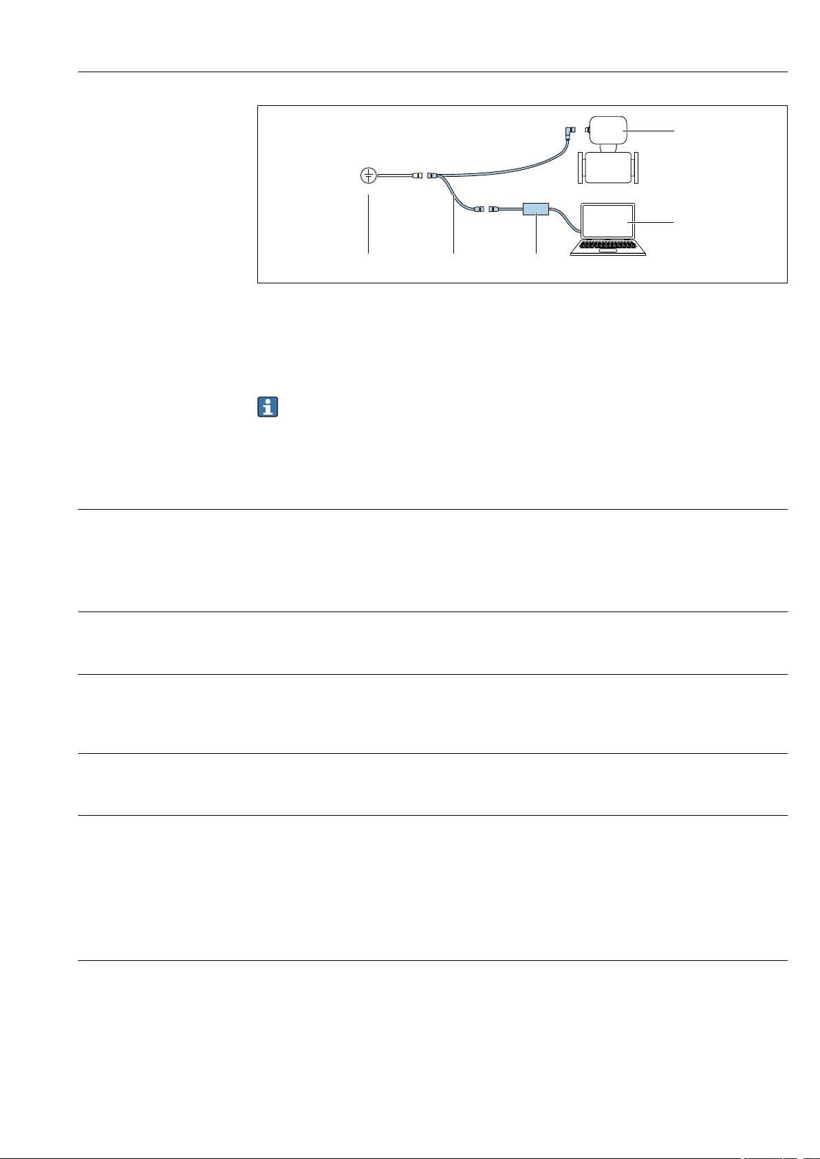
Dosimag Modbus RS485 Technical data
+
-
1 2 3
4
5
A0032567
1 Supply voltage 24 V DC
2 Service adapter
3 Commubox FXA291
4 Measuring device
5 Computer with "FieldCare" or "DeviceCare" operating tool
The service adapter, cable and Commubox FXA291 are not included in the delivery.
These components can be ordered as accessories → 62.
16.12 Certificates and approvals
CE mark The measuring system is in conformity with the statutory requirements of the applicable
EC Directives. These are listed in the corresponding EC Declaration of Conformity along
with the standards applied.
Endress+Hauser confirms successful testing of the device by affixing to it the CE mark.
C-Tick symbol The measuring system meets the EMC requirements of the "Australian Communications
and Media Authority (ACMA)".
Ex approval The devices are certified for use in hazardous areas and the relevant safety instructions are
provided in the separate "Safety Instructions" (XA) document. Reference is made to this
document on the nameplate.
Sanitary compatibility • 3A approval and EHEDG-certified
• Seals → FDA-compliant
Pressure Equipment Directive
• With the PED/G1/x (x = category) marking on the sensor nameplate, Endress+Hauser
confirms compliance with the "Essential Safety Requirements" specified in Annex I of the
Pressure Equipment Directive 97/23/EC.
• Devices not bearing this marking (PED) are designed and manufactured according to
good engineering practice. They meet the requirements of Art.3 Section 3 of the
Pressure Equipment Directive 97/23/EC. The range of application is indicated in tables 6
to 9 in Annex II of the Pressure Equipment Directive.
Measuring instrument approval
Endress+Hauser 73
Dosimag is suitable as an (optional) component for recording volume in legally regulated
measuring systems for AdBlue / DEF (Diesel Exhaust Fluid) in accordance with Appendix
MI-005 of the European Measuring Instruments Directive 2014/32/EU. Dosimag is
certified in accordance with OIML R117-1:2007 / OIML R117-2:2014 and has an MID
evaluation certificate confirming conformity with the basic requirements of the Measuring
Instruments Directive.
Page 74
Technical data Dosimag Modbus RS485
Other standards and guidelines
• EN 60529
Degrees of protection provided by enclosures (IP code)
• EN 61010-1
Safety Requirements for Electrical Equipment for Measurement, Control and Laboratory
Use
• IEC/EN 61326
Emission in accordance with Class A requirements. Electromagnetic compatibility (EMC
requirements).
• CAN/CSA C22.2 No. 61010-1-12
Safety Requirements for Electrical Equipment for Measurement, Control and Laboratory
Use, Part 1: General Requirements
• ANSI/ISA-61010-1 (82.02.01)
Safety Requirements for Electrical Equipment for Measurement, Control and Laboratory
Use – Part 1: General Requirements
16.13 Accessories
Overview of accessories available for order → 62
16.14 Supplementary documentation
For an overview of the scope of the associated Technical Documentation, refer to the
following:
• The W@M Device Viewer : Enter the serial number from the nameplate
(www.endress.com/deviceviewer)
• The Endress+Hauser Operations App: Enter the serial number from the nameplate
or scan the 2-D matrix code (QR code) on the nameplate.
Standard documentation Brief Operating Instructions
Measuring device Documentation code
Dosimag KA01175D
Description of device parameters
Measuring device Documentation code
Dosimag GP01049D
Measuring device Documentation code
Dosimag GP01048D
Technical Information
Measuring device Documentation code
Dosimag TI00066D
Pulse/frequency/status output
Option 3
Modbus RS485
Options 4, 5 and 6
74 Endress+Hauser
Page 75

Dosimag Modbus RS485 Technical data
Supplementary devicedependent documentation
Safety Instructions
Contents Documentation code
ATEX/IECEx Ex nA XA01332D
cCSAus FES0231
UL Class 1 Division 2 XA01377D
Special Documentation
Contents Documentation code
Information on Custody Transfer Measurement SD01514D
Endress+Hauser 75
Page 76

Index Dosimag Modbus RS485
Index
A
Adapters ..................................20
Adapting the diagnostic behavior ................52
Ambient temperature range ................... 19
Application .............................. 8, 64
Approvals ................................. 73
Auto scan buffer
see Modbus RS485 Modbus data map
C
C-Tick symbol .............................. 73
CE mark ................................ 9, 73
Certificates ................................ 73
Check
Connection ..............................29
Post-installation ..........................23
Checklist
Post-connection check ..................... 29
Post-installation check ..................... 23
Cleaning
Cleaning in place (CIP) ..................... 59
Exterior cleaning ......................... 59
Interior cleaning ..........................59
Sterilization in place (SIP) ...................59
Cleaning in place (CIP) ........................69
Commissioning ............................. 37
Conductivity ............................... 70
Configuring error response mode, Modbus RS485 ... 52
Connecting cable ............................24
Connecting the measuring device ................28
Grounding .............................. 28
Connecting the transmitter .................... 28
Connection
see Electrical connection
Connection conditions ........................ 24
Current consumption .........................67
D
Declaration of Conformity ...................... 9
Degree of protection ...................... 28, 69
Designated use .............................. 8
Device components .......................... 11
Device description files ....................... 33
Device documentation
Supplementary documentation ................ 7
Device locking, status ........................ 45
Device name
Sensor ................................. 13
DeviceCare ................................ 32
Diagnostic information
Communication interface ................... 52
Design, description ........................51
FieldCare ............................... 50
Overview ............................... 53
Remedy information .......................53
Diagnostic list .............................. 55
Display
Current diagnostic event ....................54
Previous diagnostic event ................... 54
Display values
For locking status .........................45
Disposal .................................. 60
Document
Function ................................ 5
Symbols used ............................. 5
Document function ........................... 5
Down pipe .................................16
E
Electrical connection
Degree of protection .......................28
Measuring device ......................... 24
Electromagnetic compatibility .................. 69
Endress+Hauser services
Maintenance ............................ 59
Repair ................................. 60
Environment
Ambient temperature ......................19
Shock resistance ..........................69
Storage temperature .......................68
Vibration resistance ....................... 69
Error messages
see Diagnostic messages
Event history ...............................55
Events list ................................. 55
Ex approval ................................73
Extended order code
Sensor ................................. 13
Exterior cleaning ............................59
F
Field of application
Residual risks ............................. 9
FieldCare ................................. 31
Device description file ......................33
Establishing a connection ................... 31
Function ............................... 31
User interface ........................... 32
Filtering the event logbook .................... 55
Firmware
Release date .............................33
Version ................................ 33
Firmware history ............................58
Fitted electrodes ............................ 72
Flow direction .............................. 17
Flow limit ................................. 70
Function check ............................. 37
Function codes ............................. 33
Functions
see Parameters
G
Galvanic isolation ........................... 66
76 Endress+Hauser
Page 77

Dosimag Modbus RS485 Index
I
Identifying the measuring device ................ 12
Incoming acceptance ......................... 12
Information on the document ................... 5
Inlet runs ................................. 18
Input .....................................64
Inspection
Received goods ...........................12
Installation ................................ 16
Installation ............................. 21
Installation conditions
Adapters ............................... 20
Down pipe .............................. 16
Inlet and outlet runs .......................18
Installation dimensions .................... 19
Mounting location ........................ 16
Orientation ............................. 17
Partially filled pipe ........................ 16
System pressure .......................... 19
Vibrations .............................. 19
Installation dimensions ....................... 19
Interior cleaning ......................... 59, 69
L
Local operation ............................. 72
Low flow cut off ............................ 66
M
Maintenance tasks .......................... 59
Replacing seals ...........................59
Manufacturing date ..........................13
Materials ................................. 71
Maximum measured error ..................... 68
Measured variables
Measured ...............................64
see Process variables
Measuring and test equipment ................. 59
Measuring device ........................... 33
Disposal ................................61
Mounting the sensor
Cleaning with pigs ......................22
Mounting the seals ..................... 23
Nominal diameter and flow ............... 23
Welded connections .................... 22
Preparing for mounting .................... 21
Removing ...............................60
structure ............................... 11
Switching on ............................ 37
Measuring instrument approval ................. 73
Measuring principle ......................... 64
Measuring range ............................64
Measuring system ........................... 64
Media ..................................... 8
Medium temperature range ....................69
Menu
Diagnostics ............................. 54
Operation .............................. 45
Setup ............................... 37, 38
Modbus RS485
Configuring error response mode ............. 52
Diagnostic information ..................... 52
Function codes ........................... 33
Modbus data map .........................34
Read access ............................. 33
Reading out data ......................... 35
Register addresses ........................ 34
Register information ...................... 34
Response time ........................... 34
Scan list ................................ 35
Write access .............................33
Mounting dimensions
see Installation dimensions
Mounting location ...........................16
Mounting preparations ....................... 21
Mounting tools ............................. 21
N
Nameplate
Sensor ................................. 13
O
Operable flow range ......................... 65
Operation ................................. 45
Operation options ........................... 30
Operational safety ............................9
Order code ................................ 13
Orientation
Filling systems ........................... 18
Orientation (vertical, horizontal) ................ 17
Outlet runs ................................ 18
Output ................................... 65
Output signal .............................. 65
P
Packaging disposal .......................... 15
Parameter settings
Administration (Submenu) .................. 56
Batch output (Submenu) ....................39
Batching (Submenu) .......................48
Communication (Submenu) ................. 41
Device information (Submenu) ............... 56
Diagnostics (Menu) ....................... 54
For the status input ....................... 38
Input values (Submenu) .................... 46
Low flow cut off (Submenu) ................. 42
Operation (Menu) ........................ 45
Process variables (Submenu) .................45
Sensor adjustment (Submenu) ............... 43
Settings batch profile 1 to n (Submenu) .........40
Setup (Menu) ............................38
Simulation (Submenu) ..................... 44
Status input (Submenu) .................... 38
System units (Submenu) ....................38
Totalizer (Submenu) .......................46
Totalizer 1 to n (Submenu) .................. 43
Totalizer handling (Submenu) ................47
Partially filled pipe .......................... 16
Endress+Hauser 77
Page 78

Index Dosimag Modbus RS485
Performance characteristics ....................67
Pin assignment, device plug .................... 25
Post-connection check (checklist) ............... 29
Post-installation check ....................... 37
Post-installation check (checklist) ............... 23
Potential equalization ........................ 67
Power consumption ..........................67
Power supply failure ......................... 67
Pressure Equipment Directive .................. 73
Pressure loss ............................... 70
Pressure tightness ...........................70
Pressure-temperature ratings .................. 70
Process conditions
Conductivity .............................70
Flow limit .............................. 70
Medium temperature ...................... 69
Pressure loss ............................ 70
Pressure tightness ........................ 70
Process connections ..........................72
Product safety ............................... 9
R
Reading measured values ......................45
Reading out diagnostic information, Modbus RS485 .. 52
Recalibration ...............................59
Reference operating conditions ................. 67
Registered trademarks .........................7
Remote operation ........................... 72
Repair ....................................60
Repeatability ...............................68
Replacement
Device ................................. 60
Wear parts ..............................60
Replacing seals ............................. 59
Requirements for personnel .....................8
Return ................................... 60
S
Safety ..................................... 8
Sanitary compatibility ........................ 73
Serial number .............................. 13
Settings
Communication interface ................... 41
Device tag .............................. 38
Resetting the totalizer ..................... 47
Status input ............................. 38
Totalizer reset ........................... 47
Shock resistance ............................ 69
Signal on alarm ............................. 66
Spare parts ................................ 60
Standards and guidelines ......................74
Sterilization in place (SIP) ..................... 69
Storage conditions ...........................15
Storage temperature ......................... 15
Storage temperature range .................... 68
structure
Measuring device ......................... 11
Submenu
Administration ...........................56
Advanced setup .......................... 42
Batch output ............................ 39
Batching ............................... 48
Communication .......................... 41
Device information ........................56
Events list .............................. 55
Input values ............................. 46
Low flow cut off .......................... 42
Process variables ......................... 45
Sensor adjustment ........................ 43
Settings batch profile 1 to n ................. 40
Simulation .............................. 44
Status input ............................. 38
System units ............................ 38
Totalizer ............................... 46
Totalizer 1 to n ...........................43
Totalizer handling ........................ 47
Supplementary documentation ................. 74
Supply unit
Requirements ............................28
Supply voltage ...........................28, 67
Surface roughness ........................... 72
Switch output .............................. 65
System design
Measuring system ........................ 64
see Measuring device design
System integration .......................... 33
System pressure ............................ 19
T
Technical data, overview ...................... 64
Temperature range
Storage temperature .......................15
Terminal assignment .........................24
Tools
For mounting ............................21
Transport ...............................15
Transporting the measuring device .............. 15
Troubleshooting
General ................................ 50
U
Use of the measuring device
Borderline cases ........................... 8
Incorrect use ............................. 8
see Designated use
V
Vibration resistance ......................... 69
Vibrations .................................19
W
W@M ................................... 59
W@M Device Viewer ..................... 12, 60
Weight
SI units ................................ 71
Transport (notes) ......................... 15
US units ................................ 71
Workplace safety ............................ 9
78 Endress+Hauser
Page 79

Page 80

www.addresses.endress.com
 Loading...