

Emerson LR128 Instruction Manual
Instruction Manual
November 2014
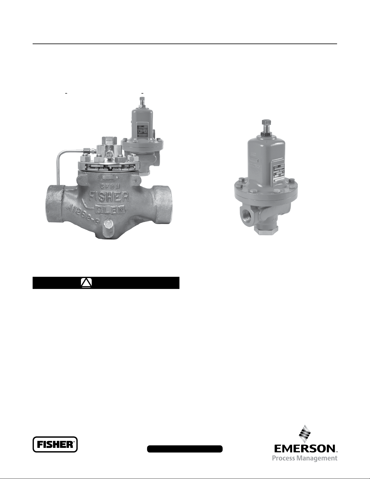
Type LR128 Relief Valve or
Backpressure Liquid Regulator
Type LR128
TYPE LR128 REGULATOR
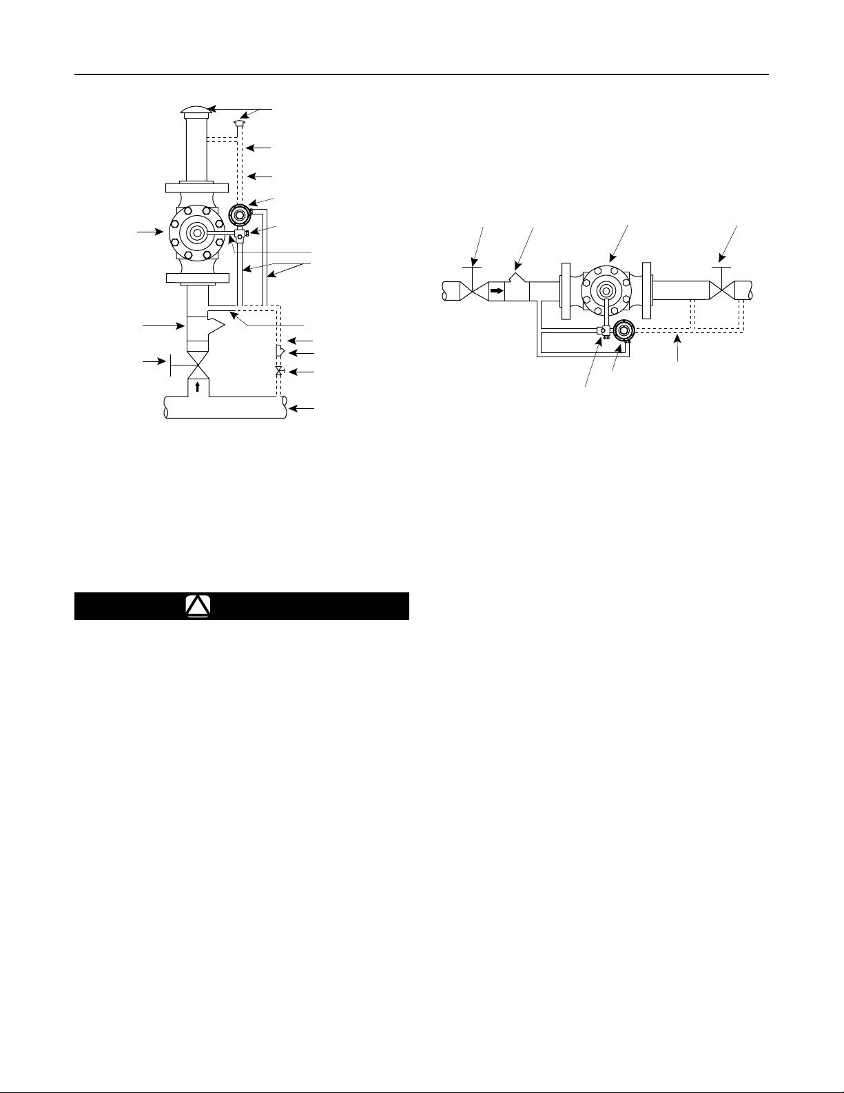
Figure 1. Type LR128 Relief Valve or Backpressure Regulator and Type MR98H Pilot
WARNING
!
Failure to follow these instructions or
to properly install and maintain this
equipment could result in bursting
of the equipment and/or chemical
contamination causing property damage
and personal injury or death.
Fisher® relief valves and backpressure
regulators must be installed, operated
and maintained in accordance with
federal, state and local codes, rules
and regulations and Emerson Process
Management Regulator Technologies, Inc.
(Emerson™) instructions.
If the relief valve or backpressure regulator
discharges process uid or a if leak
develops in the system, service to the unit
TYPE MR98H PILOT
may be required. Failure to correct trouble
could result in a hazardous condition.
Call a quali ed service person to service
the unit. Installation, operation and
maintenance procedures performed
by unquali ed personnel may result
in improper adjustment and unsafe
operation. Either condition may result
in equipment damage or personal
injury. Only a quali ed person must
install or service the relief valve or
backpressure regulator.
The Type LR128 is designed for liquid
service. Do not operate the regulator
in applications where temperatures are
below the process uid’s freezing point
or above its boiling point which are
dependent on the process uid and the
application pressures.
www.fisherregulators.com
D103578X012

Type LR128
Specications
Specications for the Type LR128 relief valve or backpressure regulator are shown below. Other information for the main
valve appears on the nameplate. The control spring range for the pilot is marked on the nameplate of Type MR98H pilot.
Main Valve Body Sizes, End Connection Styles
and Structural Design Ratings
(1)
See Table 1
Maximum Inlet Pressures
Type LR128 Main Valve: See Table 1
(1)
Type MR98H Pilot: See Table 2
Type 112 Restrictor: 1500 psig / 103 bar
Maximum Outlet Pressure
Type LR128 Main Valve: See Table 1
Type MR98H Pilot: 450 psig / 31.0 bar
Relief Set Pressure/Backpressure Control Ranges
See Table 3
Main Valve Plug Travel
1 in. / DN 25: 0.37 in. / 9.4 mm
2 in. / DN 50: 0.68 in. / 17 mm
3 in. / DN 80: 0.98 in. / 25 mm
4 in. / DN 100: 1.19 in. / 30 mm
Main Valve Minimum Differential Pressures
(1)
See Table 6
Main Valve Maximum Differential Pressures
(1)
See Table 7
Main Valve Internal Inlet Strainer Sizes
1 in. / DN 25:
12 Mesh (0.0661 in. / 1.68 mm)
(2)
2, 3 and 4 in. / DN 50, 80 and 100:
10 Mesh (0.0787 in. / 2.00 mm)
Temperature Capabilities
(1)
(2)
See Table 11
Pressure Registration
External: 1/8 NPT
Spring Case Vent
Type Y602-12
Construction Materials
Type LR128 Main Valve
Body: WCC Steel, CF8M or CF3M Stainless steel
Bonnet: LF2 Steel or 316/316L Stainless steel
Bonnet Bushing: 416 Hardened Stainless steel
Type LR128 Main Valve (continued)
Spring: 302 Stainless steel or 17-7 Stainless steel
Top Plug: 17-4 Stainless steel
Bottom Plug: 416 Stainless steel
Inlet Strainer: Stainless steel
Diaphragm: Nitrile (NBR) or Fluorocarbon (FKM)
O-Rings: Nitrile (NBR) or Fluorocarbon (FKM)
Flanged Locknut: 17-4 Stainless steel
Backup Rings: Polytetrauoroethylene (PTFE)
Upper Spring Seat: 416 Stainless steel
Indicator Protector and Cover: Plastic
Indicator Stem: 303 Stainless steel
Indicator Fitting: 416 Stainless steel
Travel Indicator Plug: 416 Stainless steel
Type MR98H Pilot
Body: WCC Steel or CF8M Stainless steel
Spring Case: WCC Steel or CF8M Stainless steel
Orice: 416 Stainless steel
Valve Plug: 416 Stainless steel
Guide and Pusher Post: 416 Stainless steel
Gasket: Nitrile (NBR) or Fluorocarbon (FKM)
O-rings: Nitrile (NBR) or Fluorocarbon (FKM)
Diaphragm: Neoprene (CR) or Fluorocarbon (FKM)
Mounting Parts
Pilot Mounting Pipe Nipple: Plated steel or
Stainless steel
Pipe Fittings: Plated steel or Stainless steel
Tubing: Stainless steel
Type 112 Restrictor
Body: 15-5 Stainless steel
Groove Valve: 416 Stainless steel
Retainer: 416 Stainless steel
Pipe Plug: 316 Stainless steel
O-rings: Nitrile (NBR) or Fluorocarbon (FKM)
Options
• Pre-piped Pilot Supply
• Travel Indicator
Cage: 15-5 Stainless steel
1. The pressure/temperature limits in this Instruction Manual and any applicable standard or code limitation should not be exceeded.
2. Nominal sieve opening.
Introduction
Scope of the Manual
This Instruction Manual provides installation, startup,
adjustment, maintenance and parts ordering information
for Type LR128 relief valve or backpressure regulator,
1/2 NPT Type MR98H pilot and Type 112 restrictor.
2
Product Description
The Type LR128 pilot-operated, relief valve or
backpressure regulator is used for liquid applications
and include a Type 112 restrictor and a 1/2 NPT
Type MR98H pilot.
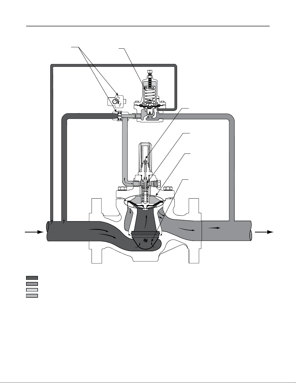
Type LR128
TYPE 112 RESTRICTOR
TYPE MR98H PILOT
O
MP
C
OPTIONAL TRAVEL INDICATOR
MAIN SPRING
DIAPHRAGM AND
PLUG ASSEMBLY
INTERNAL
STRAINER
INLET PRESSURE
OUTLET PRESSURE
ATMOSPHERIC PRESSURE
LOADING PRESSURE
TYPE LR128 WITH TYPE MR98H PILOT AND TYPE 112 RESTRICTOR
Figure 2. Type LR128 Operational Schematic
3

Type LR128
Pilot Type Description
Type MR98H – High-pressure relief pilot for 25 to
375 psig / 1.7 to 25.9 bar set pressures. Designed to
handle inlet pressures up to 450 psig / 31.0 bar.
Principle of Operation (Figure 2)
A pressure relief valve is a throttling pressure control
device that limits pressure build-up, it opens to prevent
the rise of internal pressure in excess of a specied
value. Fisher® relief valves cannot be used as ASME
safety relief valves.
A backpressure regulator is a device that maintains
a desired upstream pressure by varying the ow
in response to changes in upstream pressure. It
functions the same as a relief valve, i.e., it opens on
increasing upstream pressure.
Relief Valve
As long as the inlet pressure is below the set pressure,
the Type MR98H pilot control spring keeps the pilot
valve plug closed. Inlet pressure passes through the
Type 112 restrictor and registers as loading pressure
on top of the Type LR128 diaphragm and plug
assembly. Force from the main spring, in addition
to inlet pressure bleeding through the Type 112
restrictor, provides a downward loading pressure to
keep the main valve diaphragm and plug assembly
tightly shutoff.
When the inlet pressure rises above the set pressure,
the pressure on the pilot diaphragm overcomes the
pilot control spring and opens the pilot valve plug. The
pilot then exhausts the loading pressure from the top
of the main valve diaphragm and plug assembly. The
inlet pressure unbalance overcomes the main spring
force and opens the diaphragm and plug assembly.
The pilot continuously exhausts process uid when the
inlet pressure is above the set pressure.
pilot valve plug closed. Force from the main spring,
in addition to inlet pressure bleeding through the
Type 112 restrictor, provides downward loading
pressure to keep the main valve diaphragm and plug
assembly tightly shutoff.
When inlet pressure rises above the set pressure,
pressure on the pilot diaphragm overcomes the control
spring to stroke the valve plug open. The pilot then
exhausts loading pressure from the top of the main
valve diaphragm. Inlet pressure unbalance overcomes
the main spring force to open the main valve
diaphragm and plug assembly.
As inlet pressure drops below set pressure, the pilot
control spring overcomes the diaphragm force to
stroke the valve plug down to close. Force from the
main spring, along with pilot loading pressure, pushes
the diaphragm and plug assembly onto the tapered
edge seat, producing tight shutoff.
Installation
WARNING
!
Personal injury, equipment damage or
leakage due to escaping process uid
or bursting of pressure-containing
parts may result if the Type LR128 is
overpressured or is installed where
service conditions could exceed
the limits given in Specications
section or where conditions exceed
any ratings of the adjacent piping or
piping connections.
To avoid such injury or damage,
Type LR128 relief valve or backpressure
regulator where:
• Service conditions are within unit
capabilities (including those in the
Specications section).
install a
As the inlet pressure drops below the set pressure,
the pilot control spring closes the pilot valve plug and
the exhaust to atmosphere stops. Force from the main
spring, along with pilot loading pressure, pushes the
diaphragm and plug assembly onto the tapered edge
seat, producing tight shutoff.
Backpressure Regulator
As long as inlet pressure remains below set pressure,
the Type MR98H pilot control spring keeps the
4
• Service conditions are within applicable
codes, regulations or standards.
Additionally, physical damage to the
relief valve or backpressure regulator
could break the pilot off the main valve,
causing personal injury and property
damage due to escaping process uid.
To avoid such injury and damage, install
the regulator in a safe location.
Type LR128
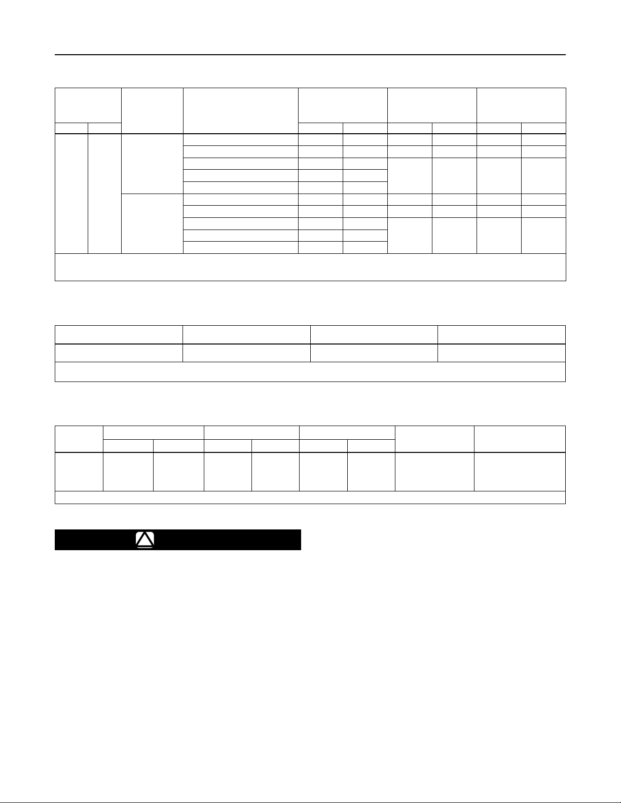
Table 1. Type LR128 Main Valve Body Sizes, End Connection Styles, Structural Design Ratings and Maximum Operating Inlet Pressures
MAIN VALVE
BODY SIZE
In. DN psig bar psig bar psig bar
1, 2,
3 and
1. The pressure/temperature limits in this Instruction Manual and any applicable standard or code limitation should not be exceeded.
2. Ratings and end connections for other than ASME standard can usually be provided. Contact your local Sales Ofce for assistance.
3. Maximum cold working pressure (CWP) per ASME B16.34 or product bulletin limit, whichever is lowest. Temperature may decrease these maximum pressures.
25, 50,
80 and
4
100
MAIN VALVE
BODY
MATERIAL
WCC Steel
CF8M
Stainless steel
END CONNECTION STYLE
NPT or SWE (1 and 2 in. only) 1500 103 450 31.0 450 31.0
CL150 RF 290 20.0 290 20.0 290 20.0
CL300 RF 750 51.7
PN 16/25/40 RF 580 40.0
NPT (1 and 2 in. only) 1440 99.2 450 31.0 450 31.0
CL150 RF 275 19.0 275 19.0 275 19.0
CL300 RF 720 49.6
PN 16/25/40 RF 580 40.0
STRUCTURAL DESIGN
(2)
RATING
(3)
Table 2. Type MR98H Pilot Maximum Cold Working Pressure
BODY SIZE
1/2 NPT
1. The pressure/temperature limits in this Instruction Manual and any applicable standard or code limitation should not be exceeded.
2. Temperature and/or the body end connection may decrease these maximum pressures.
BODY AND SPRING
CASE MATERIAL
Steel
Stainless steel
MAXIMUM INLET PRESSURE MAXIMUM OUTLET PRESSURE
450 psig / 31.0 bar 450 psig / 31.0 bar
MAXIMUM OPERATING
RELIEF (INLET)
PRESSURE INCLUDING
BUILD-UP
450 31.0 450 31.0CL600 RF 1500 103
450 31.0 450 31.0CL600 RF 1440 99.2
(3)
(1)(2)
MAXIMUM OPERATING
OUTLET PRESSURE
(1)
Table 3. Relief Set Pressure or Backpressure Control Ranges
PILOT
Type
MR98H
1. 150 to 375 psig / 10.3 to 25.9 bar spring range is for the Type MR98HH pilot construction.
SET PRESSURE RANGE SPRING WIRE DIAMETER SPRING FREE LENGTH
psig bar In. mm In. mm
25 to 75
70 to 140
130 to 200
150 to 375
1.7 to 5.2
4.8 to 9.7
9.0 to 13.8
(1)
10.3 to 25.9
WARNING
!
0.234
0.283
0.331
(1)
0.394
5.94
7.19
8.41
10.0
Liquid pressure control systems should
be designed using engineering practices
to eliminate quick control starting or
stopping of the ow stream, which can
produce water hammer.
The robust design of the Type LR128 allows this relief
valve or backpressure regulator to be installed indoors
or outdoors. Type LR128 is designed to withstand the
elements. The powder paint coating protects against
minor impacts, abrasions and corrosion. When installed
outdoors, the Type LR128 does not require protective
housing. However, the Type MR98H pilot should be
SPRING PART NUMBER
AND COLOR
ERAA01910A0, Green
ERAA01911A0, Red
ERAA02889A0, Blue
1N943427142, Unpainted
2.595
2.44
2.250
5.063
65.9
62.0
57.2
129
SPRING MATERIAL
Powder-coated steel
Powder-coated steel
Powder-coated steel
Powder-coated steel
oriented so that the pilot spring case vent is pointed
down. Otherwise, make sure the vent is protected
so that rain, moisture, insects or any debris will not
accumulate inside or block the vent assembly.
When installed indoors, no remote venting is required
except on the pilot spring case. Refer to Step 8 of the
following procedure for the correct venting practices.
1. Only personnel qualied through training and
experience should install, operate and maintain
a relief valve or backpressure regulator. Before
installation, make sure that there is no damage
to or debris in the main valve body or pilot. Also,
make sure that all tubing and piping are clean
and unobstructed.
5
Type LR128
Note
The Type LR128 internal inlet strainer
is intended to prevent occasional
large particles from entering the main
valve. If the owing media contains
continuous particles, upstream ltration
is recommended before the main valve
and in the pilot supply piping (reference
Figure 3). See the Specications section
for the corresponding mesh size of the
internal inlet strainer.
2. A Type LR128 relief valve or backpressure regulator
may be installed in any orientation, as long as ow
through the unit matches the direction of the arrow
on the main valve body and the pilot vent is pointed
down. However, for easier maintenance, install the
regulator with the bonnet up.
CAUTION
Provide adequate support to the bonnet
when disassembling Type LR128
relief valve or backpressure regulator
installed in a vertical installation or
other application where the bonnet is
not oriented upward. Without adequate
support, the bonnet may fall and cause
physical injury when the cap screws
are loosened.
3. The standard pilot mounting position is as shown
in Figure 1. Rotate the bonnet (key 2, Figure 7) or
the pilot (Figure 14) for other mounting positions.
4. An upstream control line is required and must be
installed – as shown in Figure 3 – into the 1/8 NPT
connection in the pilot body assembly (Figure 14).
Do not make the upstream pipeline connection in
or directly downstream of a turbulent area such
as a swage or elbow. A lter or strainer may be
installed in the control line upstream of the pilot
to provide clean uid. Inspect and clean this lter
regularly to make sure it is not plugged, which can
prevent proper pilot operation.
5. Run a supply pressure line from the upstream
pipeline to the restrictor inlet (use 3/8 NPT outer
diameter tubing or larger). Install a lter or strainer
upstream of the restrictor, if needed, to keep the
supply source from clogging the restrictor or pilot.
Inspect and clean this lter regularly to make sure
it has not been plugged which can prevent proper
relief valve or backpressure operation.
6. Apply a good grade of pipe compound to the
external pipeline threads for a threaded body
or use suitable line gaskets for a anged body.
Use approved piping procedures when installing
the relief valve or backpressure regulator.
WARNING
!
When used in relief valve service, the
Type LR128
the environment. In toxic or hazardous
liquid service, leaked chemical may
accumulate and cause personal injury,
death or property damage due to
escaping uid.
To prevent such injury or damage,
provide piping or tubing to vent the
hazardous liquid to a remote, safe
location away from air intakes or any
hazard-prone location.
piping must be designed and installed to
guard against excessive ow restriction.
Protect the vent line or stack opening
against condensation or clogging.
For safety during shutdown, vent valves
are required immediately upstream
and downstream of the main valve on a
backpressure or bypass installation.
7. If system operation during maintenance is required,
install isolating and vent valves as needed.
8 The pilot spring case vent (key 54, Figure 14) must
be kept open to atmospheric pressure. A clogged
pilot spring case vent may cause the relief valve
or backpressure regulator to function improperly.
To prevent plugging (and to keep the spring case
from collecting moisture, corrosive chemicals or
other foreign material) point the vent down, orient
it to the lowest possible point on the spring case
or otherwise protect it. Protect the vent assembly
from icing, moisture or debris that may cause
blockage, as required. Inspect the vent regularly
to make sure it has not been plugged. To change
the vent orientation, twist the vent assembly in the
spring case.
9. To remotely vent a spring case, remove the vent
and install obstruction-free tubing or piping into
the 1/4 NPT vent tapping. Provide protection on a
remote vent by installing a screened vent cap onto
the remote end of the vent pipe.
may leak toxic chemical to
The exhaust
6
TYPE LR128
MAIN VALVE
NON-RESTRICTIVE
VENTS AND PIPING
ALTERNATE PILOT
EXHAUST PIPING
A
TYPE MR98H PILOT
TYPE 112 RESTRICTOR
C
D
Type LR128
BLOCK VALVE STRAINER BLOCK VALVE
TYPE LR128
MAIN VALVE
STRAINER
BLOCK VALVE
RELIEF PRESSURE CONTROL
A - VENT (TO DOWNSTREAM PIPING)
C - TO TYPE LR128 LOADING CHAMBER
D - PILOT SUPPLY (FROM UPSTREAM)
Figure 3. Typical Type LR128 Installation Schematic
Startup and Shutdown
CAUTION
If pressure is introduced rst to the
main valve before the pilot, the main
valve may go wide-open and subject the
downstream system to full inlet pressure.
Note
CONTROL LINE
ALTERNATE CONTROL LINE
STRAINER
HAND VALVE
MAIN PRESSURE LINE
D
TYPE 112 RESTRICTOR
BACKPRESSURE CONTROL
C
TYPE MR98H
A
ALTERNATE PILOT
EXHAUST PIPING
Shutdown
1. Close block valve and hand valve, if installed.
2. Slowly open upstream vent valve (not shown).
Backpressure Installation (Figure 3)
Startup
1. Close upstream and downstream vent valves
(not shown).
The maximum inlet pressure for specic
constructions are given in Tables 1 and
2. Use a pressure gauge to monitor inlet
pressure during startup.
Relief Installation (Figure 3)
Startup
1. Close upstream vent valve (not shown).
2. Slowly open block valve and hand valve, if installed.
3. Adjust the pilot as needed.
2. Slowly open upstream block valve rst and then
slowly open downstream block valve.
3. Adjust the pilot as needed. If the pilot is not piped
downstream, make sure the pilot exhaust is
pointed in the correct direction.
Shutdown
1. Close upstream block valve rst and then close the
downstream block valve.
2. Open downstream and upstream vent valves
(not shown).
7
Type LR128
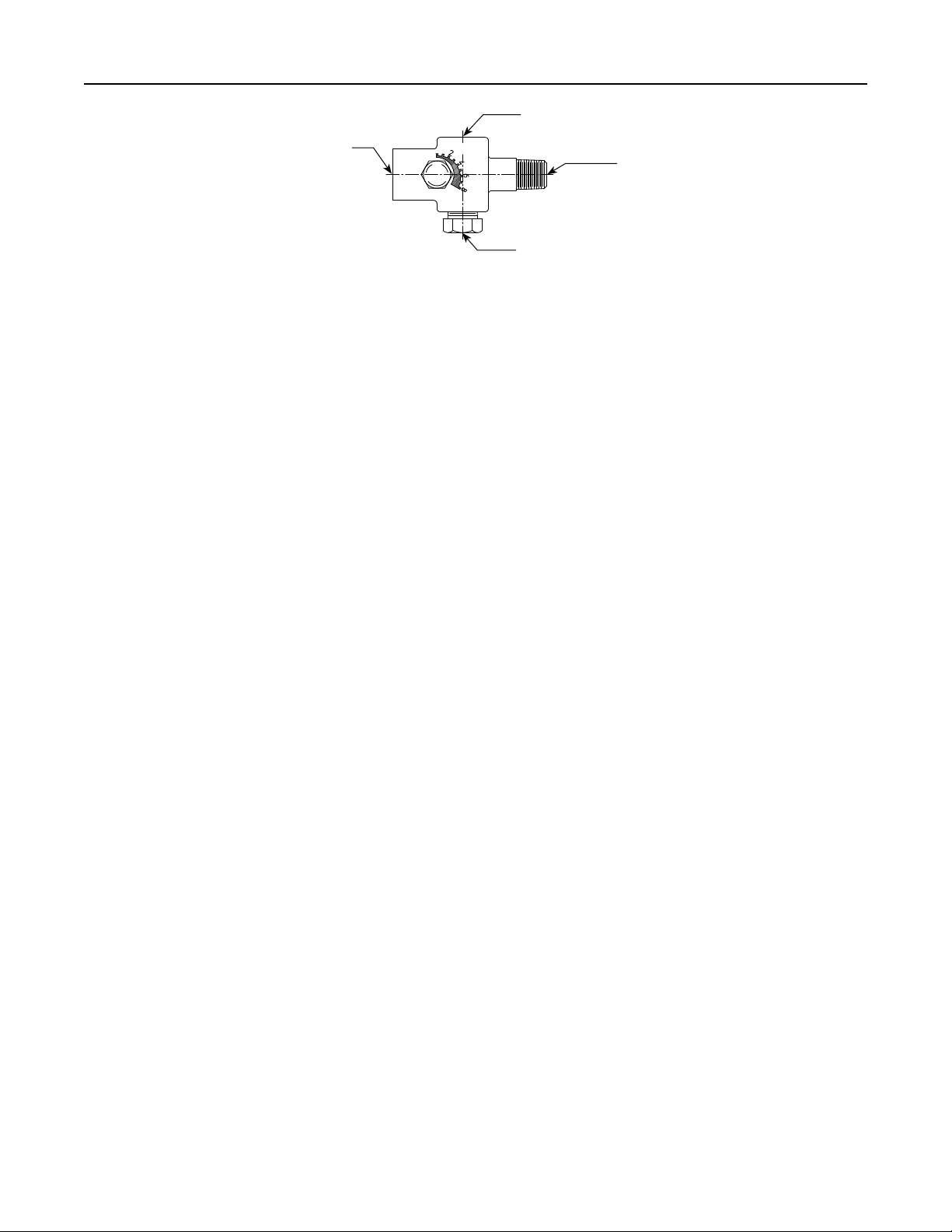
PILOT SUPPLY CONNECTION: 1/4 NPT PIPE
CONNECTS TO UPSTREAM PILOT SUPPLY TAP
LOADING CONNECTION: 1/4 NPT PIPE CONNECTS TO
TYPE LR128 DIAPHRAGM LOADING PORT
OUTLET CONNECTION: 1/4 NPT PIPE
CONNECTS TO PILOT INLET CONNECTION
11B5004-A
Figure 4. Type 112 Restrictor
Pilot Adjustment
The factory setting of the regulator can be varied
within the pressure range stamped on the nameplate.
To change the set (control) pressure, loosen the
jam nut (key 17, Figure 14) and turn the adjusting
screw (key 15) clockwise to increase set (control)
pressure or counterclockwise to decrease it. Monitor
the set (control) pressure with a test gauge during the
adjustment. Tighten the locknut to maintain the
desired setting.
Recommended set (control) pressure ranges available
and color codes of the respective springs are shown in
Table 3.
Type 112 Restrictor Adjustment (Figure 5)
OPTIONAL LOADING CONNECTION:
1/4 NPT NORMALLY PLUGGED
spaces of the restrictor. This may cause
the unit response to get slower and unit
performance to decrease. If clogging of
the restrictor is suspected, immediately
check and clean the restrictor.
Regular inspection of the restrictor
is recommended to ensure optimum
performance. Refer to the Type 112
Restrictor Maintenance section.
Likewise, debris in the process uid
may clog the restrictor. Install strainer
upstream of the regulator to prevent
debris from clogging the restrictor.
Regular inspection, maintenance and
cleaning of the strainer is recommended
to ensure optimum performance.
The Type 112 restrictor controls the relief valve or
backpressure regulator’s accuracy and speed of
response. A restrictor setting of “6” for the 1, 2 and
3 in. sizes and “8” for the 4 in. size are recommended
to optimize accuracy, speed of response and stability.
However, the restrictor can be used to ne tune the
relief valve or backpressure regulator for maximum
performance by decreasing the restrictor setting for
tighter control (increased opening speed, decreased
closing speed); or increasing the restrictor setting
for maximum stability (decreased opening speed,
increased closing speed). A lower setting also provides
a narrower proportional band for better accuracy. The
“8” position has the largest ow, is most stable and
easiest for startup. The “0” setting has the smallest
(minimum) ow passage; at no point of rotation will the
Type 112 restrictor be completely shut off.
Note
Mineral, dirt and sediments may
gradually deposit and build up inside the
Recommended Type 112 Restrictor
Settings and Restrictor Setting Guide
(Table 4 and Figure 5)
This guide can be used to adjust performance
according to application conditions. The recommended
initial setting is “6” for the 1, 2 and 3 in. sizes and “8”
for the 4 in. size (see Table 4).
Maintenance
Relief valve or backpressure regulator parts are
subject to normal wear and must be inspected
periodically and replaced as necessary. Due to the
care Emerson™ takes in meeting all manufacturing
requirements (heat treating, dimensional tolerances,
etc.), use only replacement parts manufactured or
furnished by Emerson. Also, when lubrication is
required, use a good quality lubricant and lightly coat
the recommended part.
8
W4559_1
Type LR128
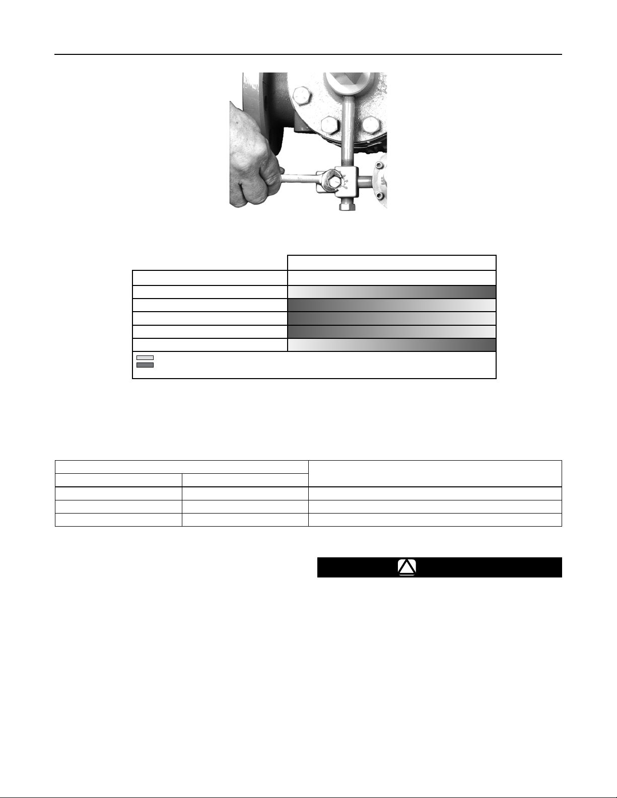
RESTRICTOR ADJUSTMENT
TYPE 112 RESTRICTOR ADJUSTMENT GUIDE
Regulator Performance 2 4 6 8
Accuracy
Hysteresis
Stability
Speed of Response (Main Valve Closing)
Speed of Response (Main Valve Opening)
Increased performance
Decreased performance
1. See Table 4 for recommended restriction settings.
RESTRICTOR SETTING GUIDE
Figure 5. Restrictor Adjustment and Restrictor Setting Guide
Table 4. Recommended Setting for Type 112 Restrictor
BODY SIZE
In. DN
1 and 2 25 and 50 “6” (other restriction settings may be used)
3 80 “6” or “8” (lower settings are not recommended)
4 100 “8” (lower settings are not recommended)
RECOMMENDED RESTRICTION SETTING
(1)
The frequency of inspection and parts replacement
depends upon the severity of service conditions,
applicable codes and government regulations and
company inspection procedures. Table 8 lists possible
relief valve or backpressure regulator issues and
solutions for them.
Type LR128 Main Valve Trim
Parts Maintenance
Instructions are given for complete disassembly and
assembly. The main valve may remain in the pipeline
during maintenance procedures. Key numbers are
referenced in Figures 7 through 11.
WARNING
!
Avoid personal injury or damage
to property from sudden release of
pressure or uncontrolled process
uid. Before starting to disassemble,
carefully release all pressures
according to the Shutdown procedure.
Use gauges to monitor inlet, loading
and outlet pressures while releasing
these pressures.
9
 Loading...