

Page 1
00825-0100-4542, Rev AA
Emerson Location Awareness
with WirelessHART® Protocol
Quick Start Guide
February 2020
Page 2

Quick Start Guide February 2020
Emerson Location Awareness safety messages
Read this Quick Start Guide before working with the product. For personal and system safety and for
optimal product performance, understand the contents completely before installing, using, or
maintaining this product.
Emerson has two toll-free assistance numbers and one international number.
NOTICE
Customer Central
1 800 999 9307 (7:00 a.m. to 7:00 p.m. CST)
National Response Center (equipment service needs)
1 800 654 7768 (24 hours a day)
International
1 952 906 8888
Nuclear qualification
The products described in this document are NOT designed for nuclear-qualified applications. Using
non-nuclear qualified products in applications that require nuclear-qualified hardware or products may
cause inaccurate readings. For information on Rosemount™ nuclear-qualified products, contact an
Emerson Sales Representative.
Wireless Gateway
The Location Anchor and all other wireless devices should be installed only after the Wireless Gateway
has been installed and is functioning properly. Wireless devices should also be powered up in order of
proximity from the Wireless Gateway, beginning with the closest. This will result in a simpler and faster
network configuration. Use caution when making changes to the TCP/IP network settings. If they are
lost or entered incorrectly, the Gateway will require a factory reset. Contact your network
administrator for information on the proper TCP/IP network settings.
Hazardous substance
Individuals handling products exposed to hazardous substances can avoid injury if they are informed of
and understand the hazard. If the returned product was exposed to a hazardous substance as defined
by OSHA, a copy of the Material Safety Data Sheet (MSDS) for each hazardous substance identified
must accompany the returned goods.
Shipping considerations
The Location Anchor unit was shipped with the battery installed. Each Location Anchor contains one
“D” size primary lithium battery. Primary lithium batteries are regulated in transportation by the U. S.
Department of Transportation and are also covered by the International Air Transport Association
(IATA), International Civil Aviation Organization (CAO), and European Ground Transportation of
Dangerous Goods (ARD). It is the shipper’s responsibility to ensure compliance with these or any other
local requirements. Consult current regulations and requirements before shipping. The polymer
enclosure has surface resistivity greater than one giga-ohm. Take care during transportation to and
from the configuration point to prevent a potential electrostatic charging hazard.
Battery considerations
Battery hazards remain when cells are discharged. Electrostatic discharge can damage electronics.
Batteries should be stored in a clean dry area. For maximum battery life, storage temperature should
not exceed 30 °C (86 °F). The Location Anchor battery shall only be replaced in a non-hazardous area.
The Personnel Tag battery is rechargeable and shall only be charged in a non-hazardous area using a Qi
certified charger.
2 Emerson.com
Page 3

February 2020 Quick Start Guide
NOTICE
Installation considerations
Only qualified personnel should perform the installation. Verify the operating atmosphere of the
transmitter is consistent with applicable hazardous area certifications. Reference the Product
Certifications section of this manual for information regarding hazardous certification. This Location
Anchor must be installed to ensure a minimum antenna separation distance of 20 cm (8 in.) from all
persons.
WARNING
Failure to follow these installation guidelines could result in death or serious injury.
Ensure only qualified personnel perform installation or service.
Explosions could result in death or serious injury.
Before connecting a handheld communicator in an explosive atmosphere, ensure the instruments are
installed in accordance with intrinsically safe or non-incendive field wiring practices.
Verify that the operating atmosphere of the transmitter is consistent with the appropriate hazardous
locations certifications.
Electrical shock could cause death or serious injury.
This Location Anchor complies with Part 15 of the FCC Rules. Operation is subject to the following
conditions: This Location Anchor may not cause harmful interference. This Location Anchor must
accept any interference received, including interference that may cause undesired operation.
This Location Anchor must be installed to ensure a minimum antenna separation distance of 20 cm
from all persons.
Physical access
Unauthorized personnel may potentially cause significant damage to an/or misconfiguration of end
users' equipment. This could be intentional or unintentional and needs to be protected against.
Physical security is an important part of any security program and fundamental to protecting your
system. Restrict physical access by unauthorized personnel to protect end user's assets. This is true for
all systems used within the facility.
Contents
Overview......................................................................................................................................5
Installation Plantweb Insight and Plantweb Insight Location application...................................... 7
Location Anchor configuration..................................................................................................... 8
Installation Location Anchor.......................................................................................................11
Location Anchor commissioning................................................................................................ 14
Operation and maintenance.......................................................................................................17
Personnel Tag configuration.......................................................................................................19
Personnel Tag mounting considerations.................................................................................... 21
Personnel Tag operation and maintenance................................................................................ 22
Quick Start Guide 3
Page 4

Quick Start Guide February 2020
Product certifications................................................................................................................. 24
Declaration of Conformity..........................................................................................................29
4 Emerson.com
Page 5
February 2020 Quick Start Guide
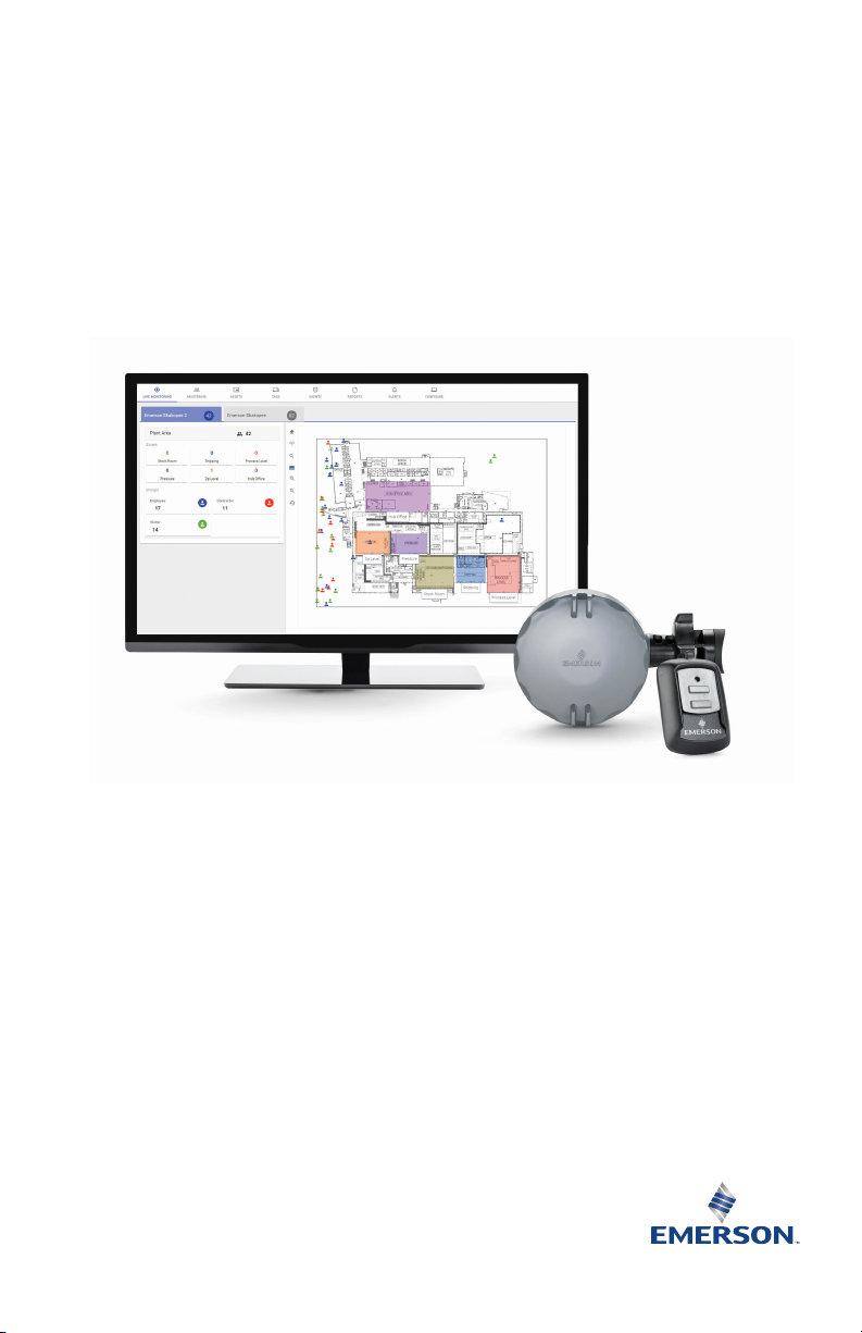
1 Overview
1.1 Location Awareness solution components
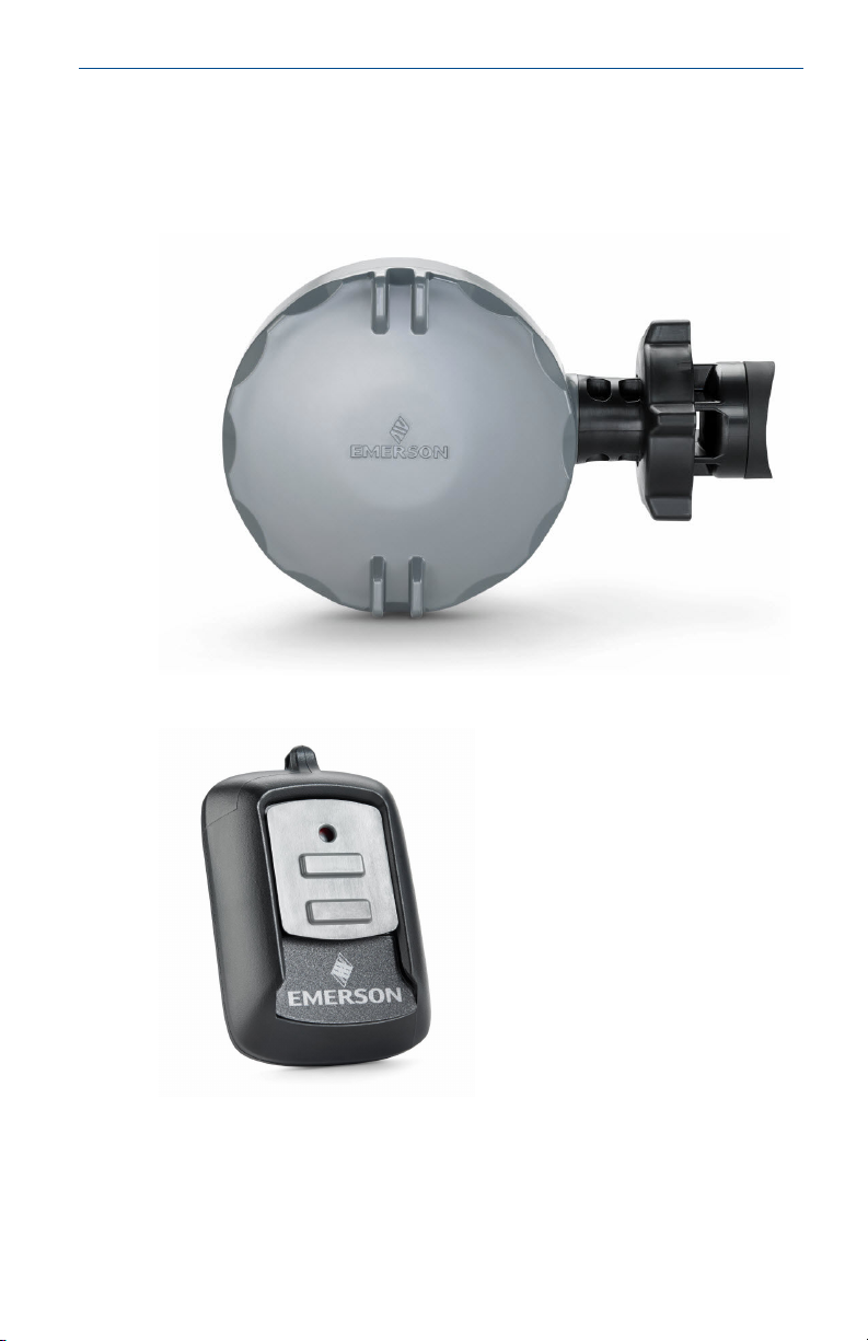
Location Anchor
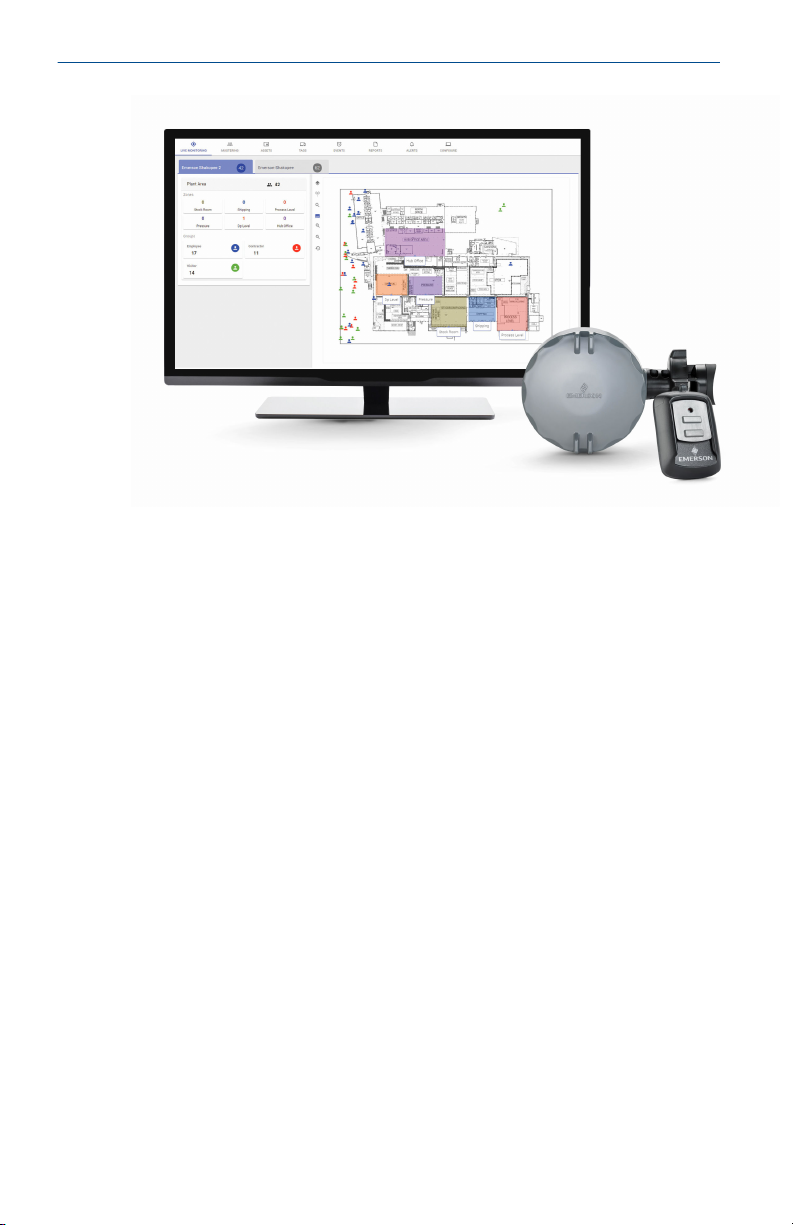
Location Personnel Tag
Quick Start Guide 5
Page 6
Quick Start Guide February 2020
Plantweb™ Insight Location application
1.2 Product recycling/disposal
Recycling of equipment and packaging should be taken into consideration.
The product and packaging should be disposed of in accordance with local
and national legislation.
6 Emerson.com
Page 7

February 2020 Quick Start Guide
2 Installation Plantweb Insight and Plantweb
Insight Location application
2.1 Install Plantweb Insight and Plantweb Insight Location application
Follow instructions in the Plantweb Insight Quick Start Guide.
Quick Start Guide 7
Page 8

Quick Start Guide February 2020
3 Location Anchor configuration
3.1 Safety messages
WARNING
Failure to follow these installation guidelines could result in death or
serious injury.
Ensure only qualified personnel perform the installation.
Explosions could result in death or serious injury.
Before connecting a handheld communicator in an explosive atmosphere,
ensure the instruments are installed in accordance with intrinsically safe or
non-incendive field wiring practices.
Verify that the operating atmosphere of the transmitter is consistent with
the appropriate hazardous locations certifications.
Electrical shock could cause death or serious injury.
Use extreme caution when making contact with the leads and terminals.
This Location Anchor complies with Part 15 of the FCC Rules. Operation is
subject to the following conditions: This Location Anchor may not cause
harmful interference. This Location Anchor must accept any interference
received, including interference that may cause undesired operation.
This Location Anchor must be installed to ensure a minimum antenna
separation distance of 20 cm from all persons.
3.2 Location Anchor configuration
Remove the Location Anchor electronics cover and connect to the HART
Communication terminals for configuration.
The Emerson Location Anchor will receive HART Communication from any
HART handheld Field Communicator or AMS Device Manager.
AMS Device Manager
AMS Device Manager can connect to devices directly, using a HART modem,
or remotely using the Gateway. To configure the Emerson Location Anchor,
double click (or right click and select Configure/Setup) on the device icon
that will appear below either the HART modem or Gateway connection tree.
8 Emerson.com
®
Page 9
February 2020 Quick Start Guide
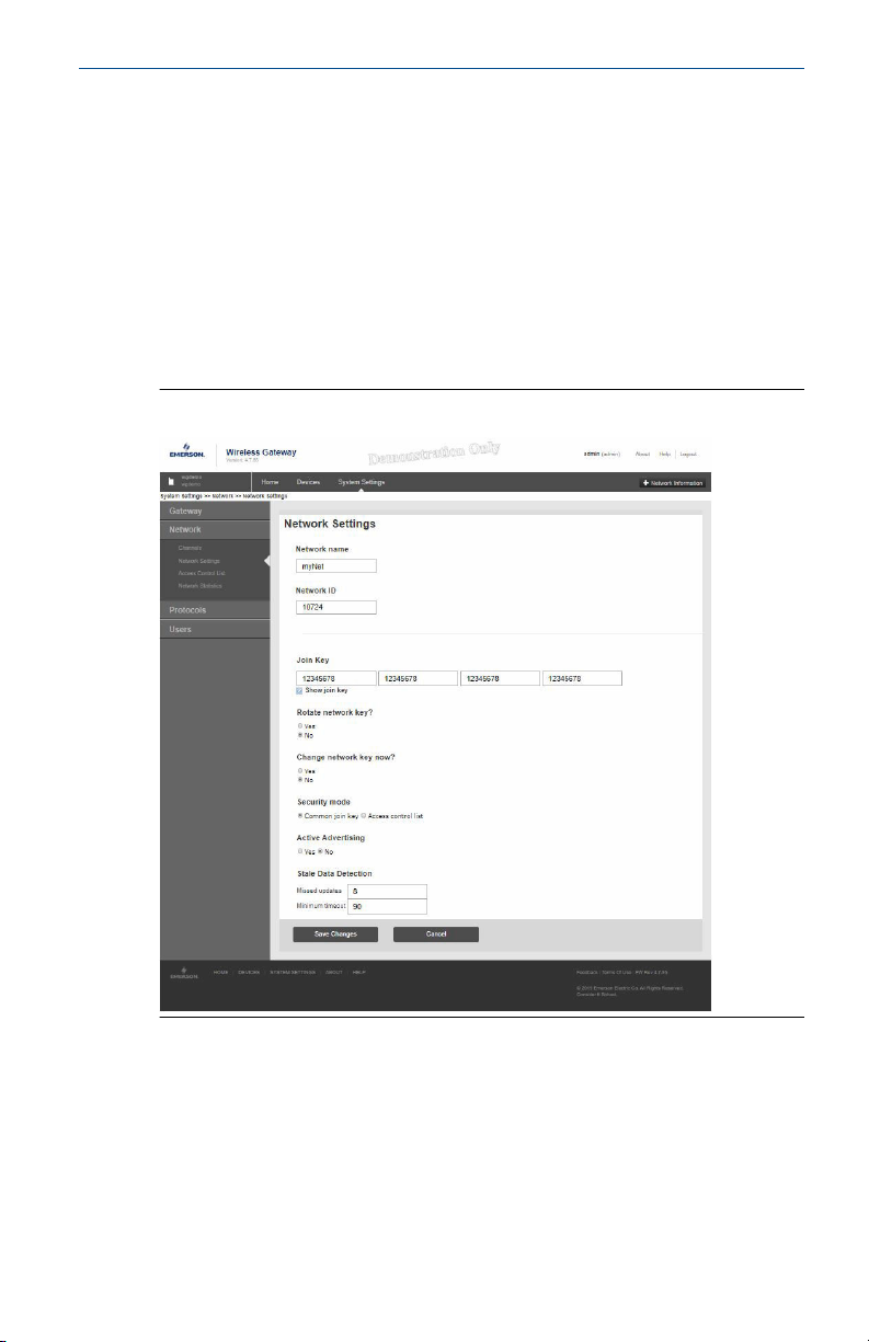
3.3 Device network configuration
To communicate with the Gateway (and ultimately the host system), the
Location Anchor must be configured to communicate with the wireless
network. Using a Field Communicator or AMS Device Manager, enter the
network ID and join key so they match the network ID and join key of the
Gateway and other devices in the network. If they do not match, the
Location Anchor will not communicate with the network. The network ID
and join key may be obtained from the Gateway on the Systems
Settings>Network>Network Settings page on the web server, shown in Figure
3-1.
Figure 3-1: Gateway Network Settings
AMS Device Manager
Right click on the Location Anchor and select Configure. When the menu
opens, select Join Device to Network and follow the method to enter the
network ID and join key. See Table 3-1 for menu items.
Quick Start Guide 9
Page 10

Quick Start Guide February 2020
Table 3-1: Device Configuration
Function Menu items
Join device to network Network ID, Set Join Key
Device information Tag, Long Tag, Descriptor, Message,
Guided setup Basic Setup, Join Device to Network,
Manual setup Wireless, Location Network, HART,
Wireless Network ID, Join Device to Network,
Date
Configure Update Rates
Security, Device Information, Power
Broadcast Information
3.4 Power down
After the Location Anchor has been configured, turn off power to the
electronics by moving the power switch to off and reinstall the cover. Power
should only be turned back on when the anchor is ready for commissioning.
10 Emerson.com
Page 11

February 2020 Quick Start Guide
4 Installation Location Anchor
4.1 Safety messages
WARNING
Failure to follow these installation guidelines could result in death or
serious injury.
Ensure only qualified personnel perform the installation.
Explosions could result in death or serious injury.
Before connecting a handheld communicator in an explosive atmosphere,
ensure the instruments are installed in accordance with intrinsically safe or
non-incendive field wiring practices.
Verify that the operating atmosphere of the transmitter is consistent with
the appropriate hazardous locations certifications.
Electrical shock could cause death or serious injury.
Use extreme caution when making contact with the leads and terminals.
This Location Anchor complies with Part 15 of the FCC Rules. Operation is
subject to the following conditions: This Location Anchor may not cause
harmful interference. This Location Anchor must accept any interference
received, including interference that may cause undesired operation.
This Location Anchor must be installed to ensure a minimum antenna
separation distance of 20 cm from all persons.
4.2 Considerations
General
The Emerson Location Awareness solution is comprised of the Emerson
Location Tag, Emerson Location Anchor, Emerson Wireless Gateways, and
Plantweb Insight Location application. Emerson Location Awareness
provides the user with safety-focused monitoring of their most valued
resource - their people. Rechargeable, battery-operated Personnel Tags
communicate with WirelessHART Anchors, creating visibility in the most
remote and hazardous areas of the facility for better personnel safety and
security. The Plantweb Insight Location application provides a streamlined
user interface that manages geofencing, safety mustering, and safety alerts,
helping the user digitally transform their facility's safety.
Quick Start Guide 11
Page 12

Quick Start Guide February 2020
4.3 Wireless considerations
Power-up sequence
The Wireless Gateway should be installed and functioning properly before
any wireless devices are powered. Battery is already installed in the Location
Anchor. Move power switch to "ON" position to power up. This results in a
simpler and faster network configuration. Enabling Active Advertising on the
Gateway ensures new devices are able to join the network faster. For more
information, see the Wireless Gateway Reference Manual.
Antenna position
The antenna is internal to the Location Anchor. To achieve optimal range
and performance, position the Location Anchor with the stem in a horizontal
position as shown in Figure 4-1. Good connectivity can also be achieved in
other orientations. The antenna should also be approximately 1 m (3 ft.)
from any large structure, building, or conductive surface, and a minimum of
2 m (6 ft.) and maximum of 4 m (13 ft.) from the ground to allow for clear
communication to other devices. Refer to best practices for additional
information on optimal mounting locations of the Location Anchor.
4.4 Electrical
Battery
The Emerson Location Anchor is self-powered. The battery is a single “D”
size primary lithium/thionyl chloride battery. Each battery contains
approximately 5.0 grams of lithium. Under normal conditions, the battery
materials are self-contained and are not reactive as long as the battery is
maintained. Care should be taken to prevent thermal, electrical, or
mechanical damage. Contacts should be protected to prevent premature
discharge. Battery cannot be changed in a hazardous location.
4.5
12 Emerson.com
Installation considerations
Procedure
1. Inspect mounting bands periodically and re-tighten if necessary.
Some loosening may occur after initial installation due to thermal
expansion/contraction.
2. The stainless steel mounting bands could be affected by stress
corrosion and potentially fail when in the presence of chlorides.
3. The Location Anchor should be installed such that steam or other
high temperature fluids do not directly impinge the housing of the
Location Anchor.
Page 13

February 2020 Quick Start Guide
4. Good connectivity can also be achieved in other orientations. The
antenna should also be approximately 1 m (3 ft.) from any large
structure, building, or conductive surface, and a minimum of 2m (6
ft.) and a max of 4m (13 ft.) from the ground to allow for clear
communication to other devices.
4.6 Mounting
Procedure
1. Locate the Location Anchor on a vertical or horizontal structure. Align
the Location Anchor as shown in Figure 4-1.
2. Tighten clamp to 10.2 N-m (90 in-lb).
3. If commissioning the Location Anchor, remove the electronics cover,
move the power switch to the on position.
4. Ensure the cover is fully tightened to prevent moisture ingress. The
lip of the polymer electronics cover should be in contact with the
surface of the polymer enclosure to ensure a proper seal. Do not
overtighten.
Figure 4-1: Location Anchor Mounting
Quick Start Guide 13
Page 14

Quick Start Guide February 2020
5 Location Anchor commissioning
5.1 Instructions and procedure safety
Instructions and procedures in this section may require special precautions
to ensure the safety of the personnel performing the operations.
Information that potentially raises safety issues is indicated by a warning
symbol (
operation preceded by this symbol.
5.2 Safety messages
WARNING
Failure to follow these installation guidelines could result in death or
serious injury.
Ensure only qualified personnel perform the installation.
Explosions could result in death or serious injury.
Before connecting a handheld communicator in an explosive atmosphere,
ensure the instruments are installed in accordance with intrinsically safe or
non-incendive field wiring practices.
Verify that the operating atmosphere of the transmitter is consistent with
the appropriate hazardous locations certifications.
). Refer to the following safety messages before performing an
Electrical shock could cause death or serious injury.
Use extreme caution when making contact with the leads and terminals.
This Location Anchor complies with Part 15 of the FCC Rules. Operation is
subject to the following conditions: This Location Anchor may not cause
harmful interference. This Location Anchor must accept any interference
received, including interference that may cause undesired operation.
This Location Anchor must be installed to ensure a minimum antenna
separation distance of 20 cm from all persons.
5.3 Verify operation
There are three methods available to verify operation:
• Field Communicator
• Gateway’s integrated web interface
• AMS Suite Wireless Configurator or AMS Device Manager
14 Emerson.com
Page 15

February 2020 Quick Start Guide
If the Emerson Location Anchor was configured with the network ID and join
key, and sufficient time has passed, the Anchor will be connected to the
network. If network ID and join key were not configured, reference
“Troubleshooting”.
Note
It may take several minutes for the Location Anchor to join the network.
Field Communicator
For WirelessHART communication, an Emerson Location Anchor Device
Driver (DD) is required. To obtain the latest DD, visit the Emerson Easy
Upgrade site at: Emerson.com/Rosemount/Device-Install-Kits.
The communication status may be verified in the wireless device using the
following the menu items.
Function Menu items
Communications Join Status, Wireless Mode, Join Mode, Number of
Available Neighbors, Number of Advertisements Heard,
Number of Join Attempts
Wireless Gateway
Using the Gateway’s web interface, navigate to the Devices page as shown
in Figure 5-1. Locate the device in question and verify all status indicators are
good (green).
Figure 5-1: Wireless Gateway Explorer page
Quick Start Guide 15
Page 16

Quick Start Guide February 2020
AMS Device Manager
When the Location Anchor has joined the network, it will appear in the AMS
Device Manager as illustrated in Figure 5-2. For WirelessHART
communication, a Location Anchor DD is required. To obtain the latest DD,
visit the Emerson Easy Upgrade site at: Emerson.com/Rosemount/Device-
Install-Kits.
Figure 5-2: AMS Device Manager
Note
Plantweb Insight Location application is provided for viewing Location
Anchor status.
Field Communicator
Note
In order to establish communication with a Field Communicator, power the
Location Anchor by switching the power switch to the “ON” position.
Function Menu items
Guided setup Basic Setup, Join Device to Network, Configure Update
Wireless Network ID, Join Device to Network, Broadcast
16 Emerson.com
Rates
Information
Page 17

February 2020 Quick Start Guide
6 Operation and maintenance
6.1 Overview
This section contains information on commissioning and operating Location
Anchors.
Field Communicator and AMS Device Manager instructions are provided for
convenience.
6.2 Instructions and procedure safety
Instructions and procedures in this section may require special precautions
to ensure the safety of the personnel performing the operations.
Information that potentially raises safety issues is indicated by a warning
symbol ( ). Refer to the following safety messages before performing an
operation preceded by this symbol.
6.3 Battery replacement
WARNING
The Emerson Location Anchor shall be used only with the battery
(00G45-9000-0001) supplied by Rosemount. This battery has been officially
tested with the Location Anchor as required by the I.S. standards during the
assessment of the Emerson Location Anchor. The battery is not replaceable
in a hazardous location. Dispose of battery in accordance with local and
national requirements.
Procedure
1. To replace the battery, remove devices from hazardous area.
2. Remove enclosure cover.
3. Switch the Location Anchor to "OFF".
4. Loosen the screw holding the electronics assembly to the enclosure.
5. Release battery connection from electronics board.
6. Loosen the two screws on the battery holder and slide the battery
holder to the left.
Note
The screws holding down the electronics board do not need to be
removed, just loosened. Take care not to let the battery fall out of
enclosure.
Quick Start Guide 17
Page 18

Quick Start Guide February 2020
7. Remove battery from enclosure.
8. Installation of new battery is the reverse of the removal.
6.4 Location Anchor status and notifications
The flashing LED indicates Location Anchor status using the colors described
in Table 6-1. To see the LED, remove the enclosure cover.
Table 6-1: Anchor LED Status Descriptions
LED color Device status
Green Functioning properly
Amber Battery is low, battery replacement
Red Battery replacement required
No color No power, verify ON/OFF switch is in “ON”
recommended
OR
Device is malfunctioning
position
18 Emerson.com
Page 19

February 2020 Quick Start Guide
7 Personnel Tag configuration
7.1 Configuring Personnel Tags
Personnel Tag configuration is completed within Plantweb Insight Location
application. First, all personnel must be identified as Assets within the Asset
page. Once personnel are identified as assets, they can be assigned to a
specific tag. Configure Personnel Tags into Plantweb Insight Location
application by following the steps below
Procedure
1. Add assests.
2. Define assets.
3. Add Tags.
Quick Start Guide 19
Page 20

Quick Start Guide February 2020
4. Name Tag.
20 Emerson.com
Page 21

February 2020 Quick Start Guide
8 Personnel Tag mounting considerations
8.1 Tag mount
The Personnel Tag has flexible wearing options to accommodate a variety of
PPE. It can be worn with a lanyard or belt clip. Lanyards are shipped with the
Personnel Tags. Belt clips can be ordered separately.
Quick Start Guide 21
Page 22

Quick Start Guide February 2020
9 Personnel Tag operation and maintenance
9.1 Personnel Tag status and notifications
The flashing LED indicates Location Tag status using the colors described in
Table 9-1. To see the LED, remove the enclosure cover.
Table 9-1: Personnel Tag LED Status Descriptions
LED color Blink rate Device status
Green 1 blink per
second
Normal operation
Green/Red Toggle blink Safety Alert button has been
Amber 1 blink per 0.5
seconds
Amber 1 blink per
second
Amber 1 blink per 2.5
seconds
Red 1 blink per
second
No color N/A No power
9.2 Personnel Tag safety alert
The Personnel Tag has a Safety Alert button than can be exposed by sliding
the grey cover downward. The red button, once pressed, sends an alert to
activated
Aggressive network search
Moderate network search
Slow network search,
conserving power
Critical low battery
AND
Battery charge required
OR
Shipping mode
22 Emerson.com
Page 23

February 2020 Quick Start Guide
the Plantweb Insight Location application to inform that the personnel may
need help.
9.3 Personnel Tag charging
The Personnel Tag has a rechargeable battery and is charged using a
certified Qi charger. Emerson offers both a single charging pad and a bulk
charging station (charges 28 tags). See Product Data Sheet for ordering
details.
WARNING
The Personnel Tag should only be charged when the tag is at room
temperature. If the tag has been in a cold environment, make sure to allow it
to warm to room temperature before charging.
Quick Start Guide 23
Page 24

Quick Start Guide February 2020
10 Product certifications
Rev: 1.0
10.1 European Directive information
A copy of the EU Declaration of Conformity can be found at the end of the
Quick Start Guide. The most recent revision of the EU Declaration of
Conformity can be found at Emerson.com/Rosemount.
10.2 Telecommunications Compliance
All wireless devices require certification to ensure they adhere to regulations
regarding the use of the RF spectrum. Nearly every country requires this type
of product certification. Emerson is working with governmental agencies
around the world to supply fully compliant products and remove the risk of
violating country directives or laws governing wireless device usage.
10.3 FCC and IC
This device complies with Part 15 of the FCC Rules. Operation is subject to
the following conditions: This devices may not cause harmful interference,
this devices must accept any interference received, including interference
that may cause undesired operation. This device must be installed to ensure
a minimum antenna separation distance of 20 cm from all persons.
This device complies with Industry Canada license-exempt RSS-247.
Operation is subject to the following two conditions: (1) this device may not
cause interference, and (2) this device must accept any interference,
including interference that may cause undesired operation of the device.
Changes or modification to the equipment not expressly approved by
Rosemount Inc. could void the user's authority to operate the equipment.
Cet appareil est conforme à la Partie 15 de la réglementation FCC. Son
fonctionnement est soumis aux conditions suivantes: Cet appareil ne doit
pas causer d'interférences nuisibles. Cet appareil doit accepter toute
interférence reçue, incluant toute interférence pouvant causer un
fonctionnement indésirable. Cet appareil doit être installé pour assurer une
distance minimum de l'antenne de séparation de 20 cm de toute personne.
Cet appareil est conforme à la norme RSS-247 Industrie Canada exempt de
licence. Son fonctionnement est soumis aux deux conditions suivantes: (1)
cet appareil ne doit pas provoquer d'interférences et (2) cet appareil doit
accepter toute interférence, y compris les interférences pouvant causer un
mauvais fonctionnement du dispositif.
Les changements ou les modifications apportés à l'équipement qui n'est pas
expressément approuvé par Rosemount Inc pourraient annuler l'autorité de
l'utilisateur à utiliser cet équipement.
24 Emerson.com
Page 25

February 2020 Quick Start Guide
10.4 Ordinary certification location from CSA
The product has been examined and tested to determine that the design
meets the basic electrical, mechanical, and fire protection requirements by
CSA, a nationally recognized test laboratory (NRTL) as accredited by the
Federal Occupational Safety and Health Administration (OSHA).
10.5 Installing in North America
The US National Electrical Code® (NEC) and the Canadian Electrical Code
(CEC) permit the use of Division marked equipment in Zones and Zone
marked equipment in Divisions. The markings must be suitable for the area
classification, gas, and temperature class. This information is clearly defined
in the respective codes.
10.6 USA
I5 Intrinsically Safe (IS)
Certificate
Standards
Geo 10
Markings
Geo 20
Markings
Special Conditions for Safe Use (X):
1. Do not replace battery when explosive atmosphere is present.
[CSA] 80004152
ANSI/UL 60079-0-2013 (r2017), ANSI/UL 60079-11Ed. 6
(March 28, 2014), ANSI/UL 61010-1-2016 Ed. 3, ANSI/UL
50E-15 Ed. 2
Intrinsically safe for:
Class I, Division 1, Groups A, B, C, D T4;
Class I Zone 0, AEx ia IIC T4 Ga
Ex ia IIC T4 Ga
T4 (-20°C ≤ Ta ≤ +60°C)
when installed per Rosemount drawing 00GEO-1106;
IP66/67;
Intrinsically safe for:
Class I, Division 1, Groups A, B, C, D T4;
Class I Zone 0, AEx ia IIC T4 Ga
Ex ia IIC T4 Ga
T4 (-40°C ≤ Ta ≤ +70°C)
when installed per Rosemount drawing 00GEO-1006;
IP66/67, Type 4X;
2. Use only 00G45-9000-0001 batteries.
Quick Start Guide 25
Page 26

Quick Start Guide February 2020
3. The surface resistivity of the housing is greater than 1GΩ. To avoid
electrostatic charge build-up, it must not be rubbed or cleaned with
solvents or a dry cloth.
Note
Conditions 1, 2, 3 do not apply to the GEO10.
4. Substitution of components may impair intrinsic safety.
10.7 Canada
I6 Canada Intrinsically Safe (IS)
Certificate
Standards
Geo 10
Markings
Geo 20
Markings
Special Conditions for Safe Use (X):
1. Do not replace battery when explosive atmosphere is present.
Ne pas remplacer les accumulateurs si une atmosphère explosive
peut être présente.
[CSA] 80004152
CAN/CSA-C22.2 No. 60079-0:19, CAN/CSA-C22.2 No.
60079-11:14, CAN/CSA- C22.2 No. 61010-1-12 (r 2017),
CSA C22.2 No. 94.1-15, CSA C22.2 No. 94.2-15
Intrinsically safe for:
Class I, Division 1, Groups A, B, C, D T4;
Class I Zone 0, AEx ia IIC T4 Ga
Ex ia IIC T4 Ga
T4 (-20°C ≤ Ta ≤ +60°C)
when installed per Rosemount drawing 00GEO-1006;
IP66/67;
Intrinsically safe for:
Class I, Division 1, Groups A, B, C, D T4;
Class I Zone 0, AEx ia IIC T4 Ga
Ex ia IIC T4 Ga
T4 (-40°C ≤ Ta ≤ +70°C)
when installed per Rosemount drawing 00GEO-1106;
IP66/67, Type 4X;
2. Use only 00G45-9000-0001 batteries.
Utiliser uniquement des accumulateurs 00G45-9000-0001.
26 Emerson.com
Page 27

February 2020 Quick Start Guide
3. The surface resistivity of the housing is greater than 1GΩ. To avoid
electrostatic charge build-up, it must not be rubbed or cleaned with
solvents or a dry cloth.
La résistivité de surface du boÎtier est supérieure à un gigaohm. Pour
éviter l’accumulation de charge électrostatique, ne pas frotter ou
nettoyer avec des produits solvants ou un chiffon sec.
Note
Conditions 1, 2, 3 do not apply to the GEO10.
4. Substitution of components may impair intrinsic safety.
La substitution de composants peut compromettre la sécurité
intrinsèque.
10.8 Europe
I1 ATEX Intrinsic Safety
10.9
Certificate
Standards
Geo 10 Markings
Geo 20 Markings
Special Conditions for Safe Use (X):
1. The plastic enclosure of the GEO20 Anchor may constitute a
potential electrostatic ignition risk and must not be rubbed or
cleaned with a dry cloth.
2. Do not change the battery when an explosive atmosphere is present.
3. Only replace battery with Rosemount Part No. 00G45-9000-0001.
Note
Conditions 1, 2, 3 do not apply to the GEO10.
SGS19ATEX0091X
EN IEC 60079-0: 2018, EN 60079-11: 2012
II 1 G Ex ia IIC T4 Ga (-20°C ≤ Ta ≤ +60°C), IP66/67;
II 1 G Ex ia IIC T4 Ga (-40°C ≤ Ta ≤ +70°C), IP66/67,
Type 4X
International
I7 IECEx Intrinsic Safety
Certificate
Standards
Geo 10 Markings
Geo 20 Markings
IECEx BAS 19.0080X
IEC 60079-0: 2017, IEC 60079-11: 2011
Ex ia IIC T4 Ga (-20°C ≤ Ta ≤ +60°C), IP66/67;
Ex ia IIC T4 Ga (-40°C ≤ Ta ≤ +70°C), IP66/67, Type 4X.
Quick Start Guide 27
Page 28

Quick Start Guide February 2020
Special Conditions for Safe Use (X):
1. The plastic enclosure of the GEO20 Anchor may constitute a
potential electrostatic ignition risk and must not be rubbed or
cleaned with a dry cloth.
2. Do not change the battery when an explosive atmosphere is present.
3. Only replace battery with Rosemount Part No. 00G45-9000-0001.
Note
Conditions 1, 2, 3 do not apply to the GEO10.
28 Emerson.com
Page 29

February 2020 Quick Start Guide
11 Declaration of Conformity
11.1 Location Awareness Personnel Tag
Quick Start Guide 29
Page 30

Quick Start Guide February 2020
30 Emerson.com
Page 31

February 2020 Quick Start Guide
Quick Start Guide 31
Page 32

Quick Start Guide February 2020
11.2 Location Awareness Anchor
32 Emerson.com
Page 33

February 2020 Quick Start Guide
Quick Start Guide 33
Page 34

Quick Start Guide February 2020
34 Emerson.com
Page 35

February 2020 Quick Start Guide
Quick Start Guide 35
Page 36

*00825-0100-4542*
00825-0100-4542, Rev. AA
Quick Start Guide
February 2020
Global Headquarters
Emerson Automation Solutions
6021 Innovation Blvd.
Shakopee, MN 55379, USA
+1 800 999 9307 or +1 952 906 8888
+1 952 204 8889
RFQ.RMD-RCC@Emerson.com
Latin America Regional Office
Emerson Automation Solutions
1300 Concord Terrace, Suite 400
Sunrise, FL 33323, USA
+1 954 846 5030
+1 954 846 5121
RFQ.RMD-RCC@Emerson.com
Asia Pacific Regional Office
Emerson Automation Solutions
1 Pandan Crescent
Singapore 128461
+65 6777 8211
+65 6777 0947
Enquiries@AP.Emerson.com
North America Regional Office
Emerson Automation Solutions
8200 Market Blvd.
Chanhassen, MN 55317, USA
+1 800 999 9307 or +1 952 906 8888
+1 952 204 8889
RMT-NA.RCCRFQ@Emerson.com
Europe Regional Office
Emerson Automation Solutions Europe
GmbH
Neuhofstrasse 19a P.O. Box 1046
CH 6340 Baar
Switzerland
+41 (0) 41 768 6111
+41 (0) 41 768 6300
RFQ.RMD-RCC@Emerson.com
Middle East and Africa Regional Office
Emerson Automation Solutions
Emerson FZE P.O. Box 17033
Jebel Ali Free Zone - South 2
Dubai, United Arab Emirates
+971 4 8118100
+971 4 8865465
RFQ.RMTMEA@Emerson.com
Linkedin.com/company/Emerson-
Automation-Solutions
Twitter.com/Rosemount_News
Facebook.com/Rosemount
Youtube.com/user/
RosemountMeasurement
©
2020 Emerson. All rights reserved.
Emerson Terms and Conditions of Sale are
available upon request. The Emerson logo is a
trademark and service mark of Emerson Electric
Co. Rosemount is a mark of one of the Emerson
family of companies. All other marks are the
property of their respective owners.
 Loading...