

Page 1
Instruction Manual
D100399X012
Fisher™ EWD, EWS, and EWT Valves
through NPS 12x8
EW Valve
July 2017
Contents
Introduction 1...................................
Scope of Manual 1.............................
Description 3.................................
Specifications 3...............................
Educational Services 4.........................
Installation 4
Inverted Globe Valve Applications
(Actuator below valve) 6.....................
Maintenance 7
Packing Lubrication 8..........................
Packing Maintenance 10........................
Trim Maintenance 14..........................
Retrofit: Installing C‐seal Trim 20................
Replacement of Installed C‐seal Trim 24...........
ENVIRO‐SEALt Bellows Seal Bonnet 27...........
Parts Ordering 32
Parts Kits 33.....................................
Parts List 36.....................................
....................................
..................................
Replacing Packing 11.......................
Trim Removal 15..........................
Lapping Metal Seats 16.....................
Valve Plug Maintenance 17..................
Trim Replacement 19......................
Trim Removal (C‐seal Constructions) 24.......
Lapping Metal Seats (C‐seal Constructions) 25..
Remachining Metal Seats
(C‐seal Constructions) 25.................
Trim Replacement (C‐seal Constructions) 26...
................................
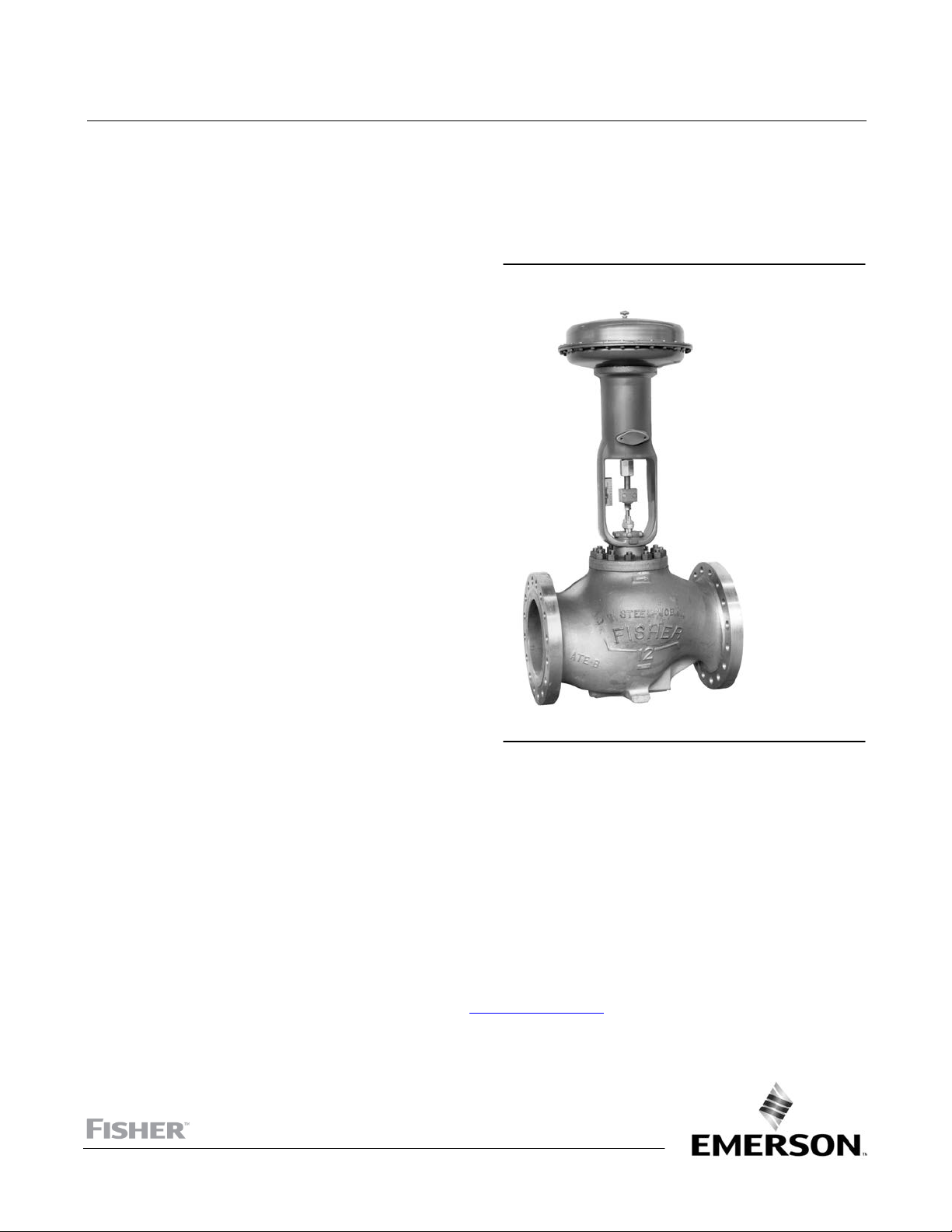
Figure 1. Fisher NPS 12x6 EW Series Valve With
667 Actuator
W2777‐2*
Introduction
Scope of Manual
This instruction manual includes installation, maintenance, and parts information for Fisher NPS 4x2 through 12x8
EWD, EWS, and EWT valves (figure 1). Refer to separate manuals for instructions covering the actuator and
accessories.
Do not install, operate, or maintain an EW valve without being fully trained and qualified in valve, actuator, and
accessory installation, operation, and maintenance. To avoid personal injury or property damage, it is important to
carefully read, understand, and follow all the contents of this manual, including all safety cautions and warnings. If you
have any questions about these instructions, contact your Emerson sales office
proceeding.
www.Fisher.com
or Local Business Partner before
Page 2

EW Valve
July 2017
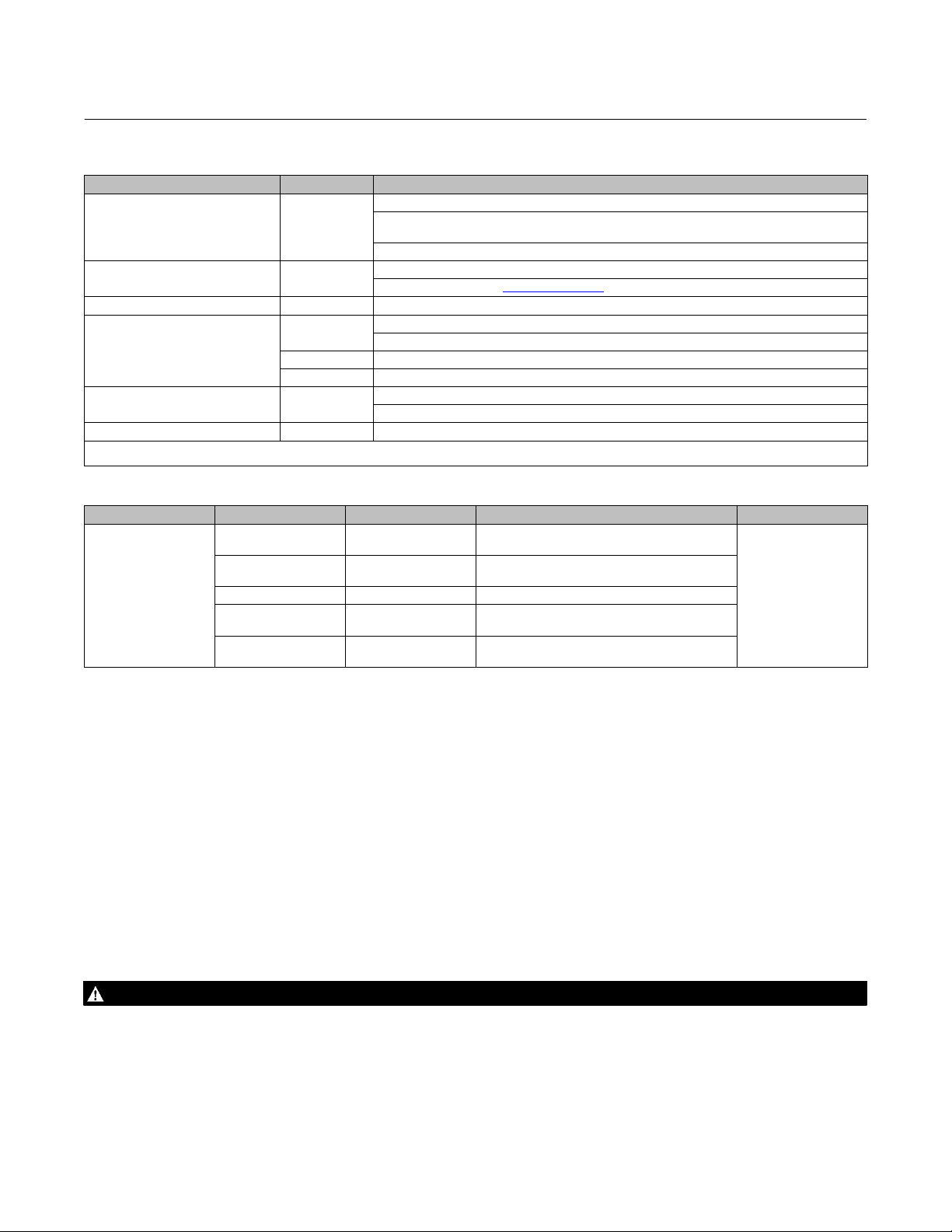
Table 1. Specifications
Instruction Manual
D100399X012
End Connection Styles
Flanged Ends: CL300, CL600, or CL900 Raised‐face or
ring‐type joint flanges per ASME B16.5
Buttwelding Ends: Styles per ASME B16.25 schedules
consistent with ASME B16.34 are: Schedules
J 80 for all CL300 and CL600 valves, Schedule J 80
or
J XXS for NPS 8x6 CL900 valves, or Schedule
J 80, J 100, or J 120 for NPS 12x8 CL900 valves.
J 40 or
Whisper Trim Cages: Always up
Cavitrol Cages: Always down
WhisperFlo Trim: Flow up (standard)—through the
seat ring and out through the cage orifices
Approximate Weights
See table 4
WhisperFlo Trim Material and Selection
Maximum Inlet Pressures, Temperatures, and
Pressure Drops
Consistent with applicable J CL300, J CL600
J CL900
(1)
(3)
pressure/temperature ratings per ASME
(2)
, or
B16.34, but do not exceed the pressure,
temperature, and pressure drop conditions specified
when the valve was ordered. Also see the Installation
section.
Also see Bulletin 80.3:010 WhisperFlot Aerodynamic
J 410 Stainless Steel
J Others per application
See appropriate valve body bulletin
WhisperFlo Pressure/Temperature Capability
J -29 to 427_C (-20 to 800_F)
J Others per application
See appropriate valve body bulletin for
complementary information
Attenuation Trims, D102362X012
WhisperFlo Aerodynamic Trim Pressure Ratings
Shutoff Classifications
Up to 1500 psi drop
See table 2
C‐seal trim: High‐temperature, Class V per ANSI/FCI
70‐2 and IEC 60534‐4
See table 3
WhisperFlo Trim:
J Class IV per ANSI/FCI 70‐2 and IEC 60534‐4
J Others per application
Flow Characteristics
Standard Cages:
J equal percentage
J Linear, J quick opening, or
Whisper Trimt and Cavitrolt Cages: Linear
WhisperFlo Trim: Linear (restricted linear cages and
special, characterized cages are available--consult
your Emerson sales office
or Local Business Partner)
WhisperFlo Velocity Limits
WhisperFlo trim is designed for 0.3 MACH as an
inherent outlet velocity limit. Variations higher and
lower may be applied per special applications
WhisperFlo Rangeability
100:1
WhisperFlo Noise Attenuation
Approximately -40 dBA maximum depending on the
nP/P
ratio per IEC 534‐8‐3 calculation procedure
1
See Fisher Specification Manager
Additional Specifications
Flow Directions
EWS and Standard Cage: Normally up
EWD or EWT with Standard Cage: Normally down
1. The pressure or temperature limits in this manual and any applicable standard limitations should not be exceeded.
2. Certain bonnet bolting material selections may require a CL600 easy‐e valve assembly to be derated. Contact your Emerson sales office.
3. There are two different CL900 NPS 8x6 valve bodies, one for use only with Cavitrol III cages and the other for use with all other constructions. A CL900 valve with Cavitrol III cage can take full
CL900 pressure drops. For information on other NPS 8x6 constructions that can take full CL900 pressure drops, contact your Emerson sales office. All other trim constructions are limited to
CL600 pressure/temperature limits even though installed in a CL900 valve.
For specifications such as materials, port diameters,
valve plug travels, yoke boss diameters, and stem
diameters, refer to the Parts List
(1,2)
2
Page 3
Instruction Manual
D100399X012
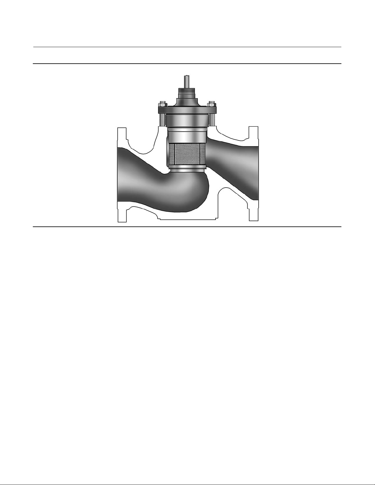
Figure 2. Cutaway Detail of the Fisher WhisperFlo Trim, Valve Body Typical
EW Valve
July 2017
W6825‐1
Description
These single‐port globe‐style valves have cage guiding, clamped seat rings, and push‐down‐to‐close valve plug action.
Valve configurations are as follows:
EWD: Balanced valve plug with metal‐to‐metal seating for all general applications over a wide range of pressure drops
and temperatures.
C‐seal trim is available for EWD valves, CL300 and CL600, in sizes NPS 6x4x2‐1/2, 6x4, 8x4, 8x6, 12x6, 10x8, and 12x8.
With C‐seal trim, a balanced valve can achieve high‐temperature, Class V shutoff. Because the C‐seal plug seal is
formed from metal (N07718 nickel alloy) rather than an elastomer, a valve equipped with the C‐seal trim can be
applied in processes with a fluid temperature of up to 593_C (1100_F), provided other material limits are not
exceeded.
EWS: Unbalanced valve plug with metal‐to‐metal or optional metal‐to‐PTFE seating for all general applications
requiring better shutoff capabilities than can be obtained with the EWD valve.
EWT: Balanced valve plug with either metal‐to‐PTFE seating (standard for all except Cavitrol III cages) for stringent
shutoff requirements or metal‐to‐metal seating (standard for Cavitrol III cages, optional for all others) for higher
temperatures.
Control valves with WhisperFlo cages (figure 2) provide additional attenuation for aerodynamic noise in very
demanding vapor or gas applications with high‐pressure drops. A WhisperFlo cage with an appropriately sized valve
body is designed to reduce the noise level up to -40 dBA. For special applications, -50 dBA attenuation can be
achieved.
Specifications
Typical specifications for these valves are shown in table 1.
3
Page 4
EW Valve
July 2017
Instruction Manual
D100399X012
Table 2. Shutoff Classification Per ANSI/FCI 70‐2 and IEC 60534‐4
Valve Seating Shutoff Class
EWD Metal
EWS Metal
EWS PTFE VI
EWT with all except
Cavitrol III cages
EWT with
1‐stage Cavitrol III cage
EWT with 2‐stage Cavitrol III cage Metal V
1. Class V shutoff for EWT requires spring loaded seal ring, radius‐seat plug, wide‐bevel seat ring, and seat lapping. Not available with 8‐inch port, quick‐opening cage. Not available with
S31600 (316 SST) valve plug and seat ring.
PTFE
Metal IV (standard)
Metal V (optional)
Metal
II (standard)
III (optional for NPS 6x4 through 12x6 valves with optional single graphite piston ring or for
NPS 10x8 and 12x8 valves with optional double piston rings)
IV (optional for NPS 6x4 through 12x8 valves with optional multiple graphite piston rings)
IV (standard)
V (optional, consult your Emerson sales office or Local Business Partner)
Standard Air Test (maximum leakage is 0.05 mL/min/psid/inch port diameter)
V (optional)
(1)
IV (standard)
V (optional)
Table 3. Additional Shutoff Classification for C‐seal Trim Per ANSI/FCI 70‐2 and IEC 60534‐4
Valve Valve Size, NPS Port Diameter, Inches Cage Style Leakage Class
Equal Percentage, Linear, Whisper I,
Cavitrol III (2‐stage)
Equal Percentage, Linear, Whisper I,
Cavitrol III (1‐stage)
Equal Percentage, Linear, Whisper I,
Cavitrol III (1‐stage)
Equal Percentage, Linear, Whisper I,
Cavitrol III (1‐stage)
V (for port
diameters from 2.875
through 8‐inch with
optional C‐seal trim)
EWD
(CL300, CL600)
6x4x2‐1/2 2.875
6x4
8x4
8x6 and 12x6 5.375 Whisper III (A3, B3, D3, D3), Cavitrol III (2‐stage)
8x6
12x6
10x8
12x8
4.375
7
8
Educational Services
For information on available courses for the Fisher EW valve, as well as a variety of other products, contact:
Emerson Automation Solutions
Educational Services - Registration
Phone: 1-641-754-3771 or 1-800-338-8158
E-mail: education@emerson.com
emerson.com/fishervalvetraining
Installation
WARNING
Always wear protective gloves, clothing, and eyewear when performing any installation operations to avoid personal
injury.
Personal injury or equipment damage caused by sudden release of pressure or bursting of parts may result if the valve
assembly is installed where service conditions could exceed the limits given in table 1 or on the appropriate nameplates. To
avoid such injury or damage, provide a relief valve for overpressure protection as required by government or accepted
industry codes and good engineering practices.
4
Page 5
Instruction Manual
D100399X012
EW Valve
July 2017
Check with your process or safety engineer for any additional measures that must be taken to protect against process
media.
If installing into an existing application, also refer to the WARNING at the beginning of the Maintenance section in this
instruction manual.
CAUTION
When ordered, the valve configuration and construction materials were selected to meet particular pressure, temperature,
pressure drop and controlled fluid conditions. Responsibility for the safety of process media and compatibility of valve
materials with process media rests solely with the purchaser and end‐user. Since some body/trim material combinations
are limited in their pressure drop and temperature ranges, do not apply any other conditions to the valve without first
contacting your Emerson sales office
Before installing the valve, inspect the valve and pipelines for any damage and any foreign material which may cause
product damage.
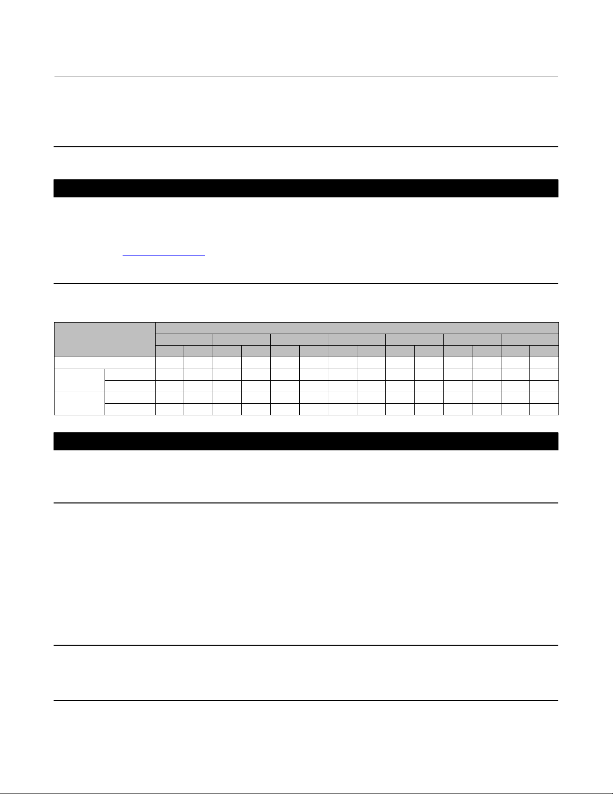
Table 4. Approximate Weights
END CONNECTION
Kg Lb Kg Lb Kg Lb Kg Lb Kg Lb Kg Lb Kg Lb
CL300 (flanged only) 84 185 150 330 234 515 284 625 567 1250 500 1102 653 1440
CL600
CL900
Flanged 100 220 195 430 272 600 308 680 744 1640 721 1590 857 1890
Buttwelding 61 135 122 270 177 390 272 600 512 1130 526 1160 658 1450
Flanged ‐ ‐ ‐ ‐ ‐ ‐ ‐ ‐ ‐ ‐ ‐ ‐ ‐ ‐ ‐ ‐ ‐ ‐ 612 1350 ‐ ‐ ‐ ‐ ‐ ‐ ‐ ‐ ‐ ‐ ‐ ‐ 1361 3000
Buttwelding ‐ ‐ ‐ ‐ ‐ ‐ ‐ ‐ ‐ ‐ ‐ ‐ ‐ ‐ ‐ ‐ ‐ ‐ 454 1000 ‐ ‐ ‐ ‐ ‐ ‐ ‐ ‐ ‐ ‐ ‐ ‐ 1293 2850
or Local Business Partner.
VALVE SIZE, NPS
4X2 6X4 8X4 8X6 10X8 12X6 12X8
CAUTION
If hoisting the valve, use a nylon sling to protect the surfaces. Carefully position the sling to prevent damage to the actuator
tubing and any accessories. Also, take care to prevent people from being injured in case the hoist or rigging slips
unexpectedly. Refer to table 4 for valve assembly weights. Be sure to use adequately sized hoists and chains or slings to
handle the valve.
1. Before installing the valve, inspect the valve body cavity and associated equipment for any damage and any foreign
material.
2. Make certain the valve body interior is clean, that pipelines are free of foreign material, and that the valve is
oriented so that pipeline flow is in the same direction as the arrow on the side of the valve.
3. Install the control valve assembly in any orientation unless limited by seismic criteria. However, the normal method
is with the actuator vertical above the valve. Other positions may result in uneven valve plug and cage wear and in
improper operation. With some valves, the actuator may also need to be supported when it is not vertical. For more
information, consult your Emerson sales office or Local Business Partner.
Note
If installing a valve with small internal flow passages, such as with WhisperFlo, Whisper Trim, or Cavitrol cages, consider installing
an upstream strainer to prevent the lodging of particles in these passages. This is especially important if the pipeline cannot be
thoroughly cleaned or if the flowing medium is not clean.
5
Page 6

EW Valve
July 2017
4. Use accepted piping and welding practices when installing the valve in the line. For flanged valve bodies, use a
suitable gasket between the valve body and pipeline flanges.
Instruction Manual
D100399X012
CAUTION
Depending on valve body materials used, post weld heat treating may be required. If so, damage to internal elastomeric
and plastic parts, as well as internal metal parts is possible. Shrink‐fit pieces and threaded connections may also loosen. In
general, if post weld heat treating is to be performed, remove all trim parts. Contact your Emerson sales office
Business Partner for additional information.
5. With a leak‐off bonnet construction, remove the pipe plugs (keys 14 and 16, figure 21) from the bonnet to hook up
the leak‐off piping. If continuous operation is required during inspection or maintenance, install a three‐valve
bypass around the control valve assembly.
6. If the actuator and valve are shipped separately, refer to the actuator mounting procedure in the appropriate
actuator instruction manual.
or Local
WARNING
Personal injury could result from packing leakage. Valve packing was tightened before shipment; however, the packing
might require some readjustment to meet specific service conditions. Check with your process or safety engineer for any
additional measures that must be taken to protect against process media.
Valves with ENVIRO‐SEAL live‐loaded packing or HIGH‐SEAL live‐loaded packing will not require this initial
re‐adjustment. See Fisher instruction manuals, ENVIRO‐SEAL Packing System for Sliding‐Stem Valves, D101642X012
or HIGH‐SEAL Live‐Loaded Packing System, D101453X012
convert your present packing arrangement to ENVIRO‐SEAL packing, refer to the retrofit kits listed in the parts kit
sub‐section near the end of this manual.
, (as appropriate), for packing instructions. If you wish to
,
Inverted Globe Valve Applications (Actuator below valve)
Due to space restrictions in your application, you may be required to mount the valve/actuator assembly in an inverted
orientation, with the actuator positioned below the valve. If so, the following procedures will help you with
disassembly and assembly techniques.
WARNING
Avoid personal injury or property damage caused by components dropping.
With the valve/actuator upside down, components may drop during disassembly or assembly. Be careful not to position
yourself below the valve in the path of falling parts.
As the bonnet/plug/cage is lowered from the valve body, the center of gravity will be above the lifting points. Take care to
prevent the assembly from tipping over as it is lowered. Either leave the actuator attached to the plug and bonnet, attach
straps to the stem, or provide other means to prevent tipping.
Disassembly
1. Provide adequate support to the actuator while removing it from the bonnet.
6
Page 7

Instruction Manual
D100399X012
EW Valve
July 2017
2. Provide adequate support to the bonnet while removing the bonnet nuts.
3. Be aware that the bonnet/plug/cage may tip over as they are lowered from the valve body. Make provision to
prevent tipping.
4. Be aware that the cage and seat ring may not come out with the bonnet and plug/stem assembly. If this occurs,
make provision to support these parts, as they may fall out unexpectedly.
Assembly
1. Start this assembly procedure with the plug/stem assembly already installed in the bonnet.
2. Put the gaskets and cage onto the bonnet and plug.
3. Place the seat ring with the seat ring gasket onto the cage, if applicable with the valve design.
4. Raise this bonnet/plug/cage assembly up into the valve body. Make provision to prevent tipping of these parts as
they are being raised into the valve body.
5. Torque the bonnet nuts.
6. Mount the actuator.
Maintenance
Valve parts are subject to normal wear and must be inspected and replaced as necessary. Inspection and maintenance
frequency depends on the severity of service conditions. This section includes instructions for packing lubrication,
packing maintenance, trim maintenance, lapping metal seats, and ENVIRO‐SEAL bellows seal bonnet replacement. All
maintenance operations may be performed with the valve in the line.
WARNING
Avoid personal injury or property damage from sudden release of process pressure. Before performing any maintenance
operations:
D Do not remove the actuator from the valve while the valve is still pressurized.
D Always wear protective gloves, clothing, and eyewear when performing any maintenance operations to avoid personal
injury.
D Disconnect any operating lines providing air pressure, electric power, or a control signal to the actuator. Be sure the
actuator cannot suddenly open or close the valve.
D Use bypass valves or completely shut off the process to isolate the valve from process pressure. Relieve process pressure
on both sides of the valve. Drain the process media from both sides of the valve.
D Vent the pneumatic actuator loading pressure and relieve any actuator spring precompression.
D Use lock‐out procedures to be sure that the above measures stay in effect while you work on the equipment.
D The valve packing box may contain process fluids that are pressurized, even when the valve has been removed from the
pipeline. Process fluids may spray out under pressure when removing the packing hardware or packing rings, or when
loosening the packing box pipe plug.
D Check with your process or safety engineer for any additional measures that must be taken to protect against process
media.
CAUTION
Follow instructions carefully to avoid damaging the product surfaces, which could result in damage to the product.
7
Page 8

EW Valve
July 2017
Note
Whenever a gasket seal is disturbed by removing or shifting gasketed parts, install a new gasket upon reassembly. This is necessary
to ensure a good gasket seal because the used gasket may not seal properly.
Instruction Manual
D100399X012
Figure 3. Lubricator and Lubricator/Isolating Valve (optional)
LUBRICATOR
10A9421‐A
AJ5428‐D
A0832‐2
LUBRICATOR/ISOLATING VALVE
Packing Lubrication
CAUTION
Do not lubricate graphite packing. Graphite packing is self-lubricated. Additional lubrication may result in slip-stick
movement of the valve.
Note
ENVIRO‐SEAL or HIGH‐SEAL packing does not require lubrication.
WARNING
To avoid personal injury or property damage resulting from fire or explosion, do not lubricate packing used in oxygen
service or in processes with temperatures over 260_C (500_F).
If a lubricator or lubricator/isolating valve (figure 3) is provided for PTFE/composition or other packings that require
lubrication, it will be installed in place of the pipe plug (key 14, figure 21). Use a good quality silicon‐base lubricant. Do
not lubricate packing used in oxygen service or in processes with temperatures over 260_C (500_F). To operate the
lubricator, simply turn the cap screw clockwise to force the lubricant into the packing box. The lubricator/isolating
valve operates the same way, except open the isolating valve before turning the cap screw and then close the isolating
valve after lubrication is completed.
8
Page 9
Instruction Manual
D100399X012
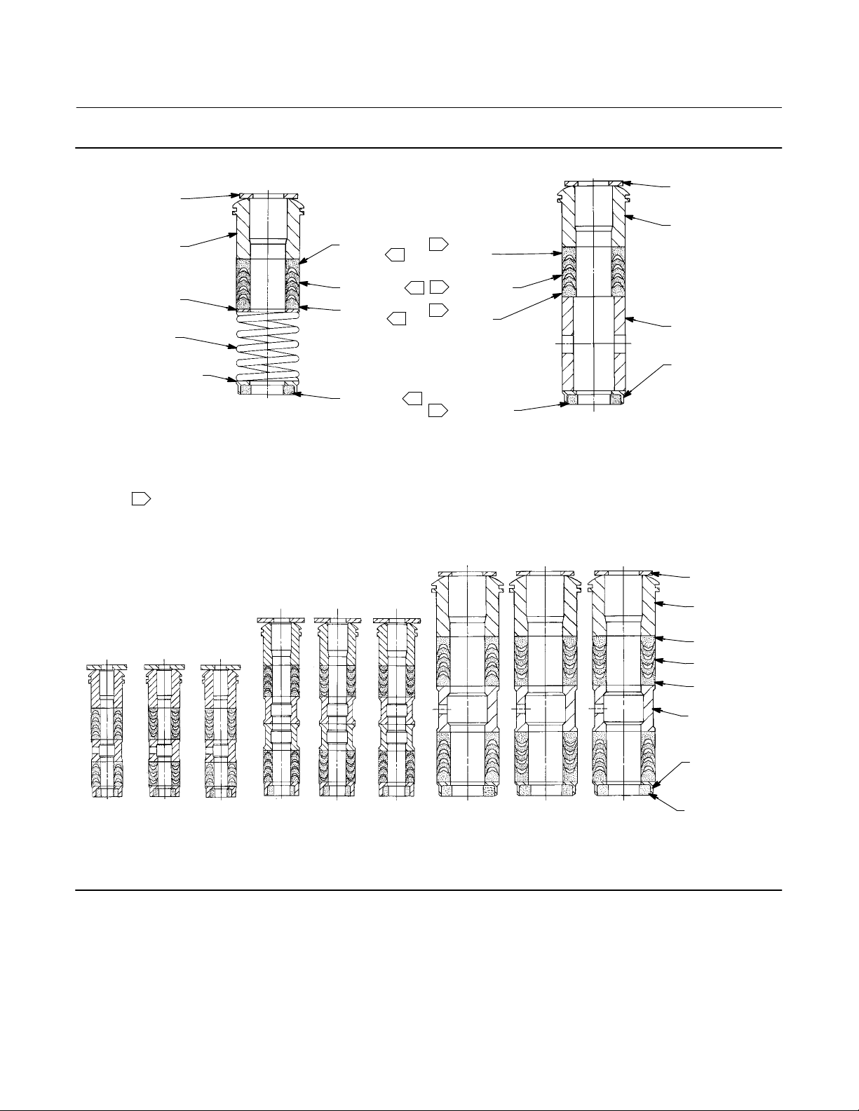
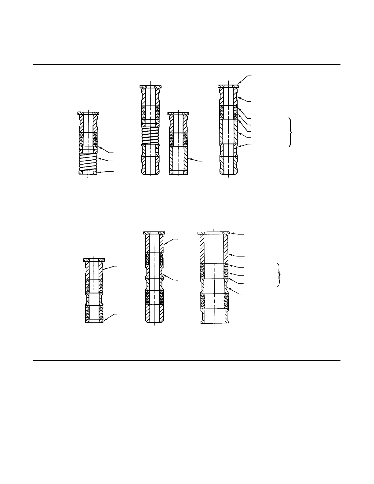
Figure 4. PTFE V‐Ring Packing Arrangements
EW Valve
July 2017
UPPER WIPER
(KEY 12)
PACKING
FOLLOWER
(KEY 13)
WASHER
(KEY 10)
SPRING
(KEY 8)
PACKING BOX
RING (KEY 11)
12A7837−A/IL
FOR S31600 (316 SST) OR
S17400 (17‐4PH SST)
METAL PACKING BOX PARTS
NOTE:
1
PACKING SET (KEY 6) (2 REQ'D FOR DOUBLE ARRANGEMENTS).
B2398
FEMALE
ADAPTOR
PACKING RING
MALE
ADAPTOR
LOWER WIPER
1
1
1
1
1
1
1
1
SINGLE ARRANGEMENTS
FEMALE
ADAPTOR
PACKING RING
MALE
ADAPTOR
LOWER WIPER
FOR ALL OTHER METAL PACKING
BOX PART MATERIALS
UPPER WIPER
(KEY 12)
PACKING
FOLLOWER
(KEY 13)
SPACER
(KEY 8)
PACKING BOX
RING (KEY 11)
UPPER WIPER
(KEY 12)
PACKING
FOLLOWER (KEY 13)
12A8187-C 12A7814-C 12A7839-A
ASSEMBLY 1
(POSITIVE
PRESSURES)
ASSEMBLY 2
(VACUUM)
ASSEMBLY 3
(POSITIVE
PRESSURES
& VACUUM)
ASSEMBLY 1
(POSITIVE
PRESSURES)
ASSEMBLY 2
(VACUUM)
ASSEMBLY 3
(POSITIVE
PRESSURES
& VACUUM)
ASSEMBLY 1
(POSITIVE
PRESSURES)
ASSEMBLY 2
9.5 mm (3/8 INCH) STEM 12.7 mm (1/2 INCH) STEM 19.1, 25.4, OR 31.8 mm
(3/4, 1, OR 1‐1/4 INCH) STEM
B1428‐2
DOUBLE ARRANGEMENTS
(VACUUM)
ASSEMBLY 3
(POSITIVE
PRESSURES
& VACUUM)
MALE ADAPTOR
PACKING RING
FEMALE ADAPTOR
LANTERN RING
(KEY 8)
PACKING BOX
RING (KEY 11)
LOWER WIPER
9
Page 10
EW Valve
July 2017
Instruction Manual
D100399X012
Packing Maintenance
Note
For valves with ENVIRO‐SEAL live‐loaded packing, see the Fisher instruction manual, ENVIRO‐SEAL Packing System for Sliding‐Stem
Valves, D101642X012
HIGH‐SEAL Live‐Loaded Packing System, D101453X012
Key numbers refer to figure 4 for PTFE V‐ring packing and to figure 5 for PTFE/composition packing, unless otherwise
indicated.
For spring‐loaded single PTFE V‐ring packing, the spring (key 8, figure 4) maintains a sealing force on the packing. If
leakage is noted around the packing follower (key 13, figure 4), check to be sure the shoulder on the packing follower
is touching the bonnet. If the shoulder is not touching the bonnet, tighten the packing flange nuts (key 5, figure 21)
until the shoulder is against the bonnet. If leakage cannot be stopped in this manner, go to the Replacing Packing
procedure.
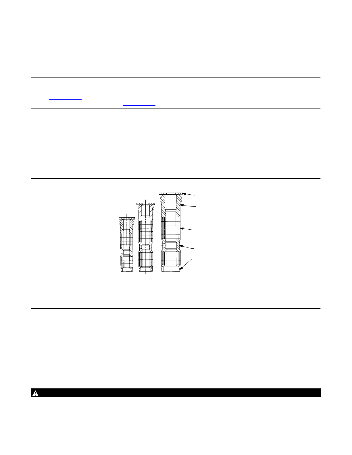
Figure 5. Detail of PTFE/Composition Packing Arrangements
, for packing instructions. For valves with HIGH‐SEAL live‐loaded packing, see the Fisher instruction manual,
, for packing instructions.
UPPER WIPER
(KEY 12)
PACKING
FOLLOWER
(KEY 13)
PACKING RING
(KEY 7)
LANTERN RING
(KEY 8)
PACKING BOX
RING (KEY 11)
12A8188‐A
12A7815‐A
12A8173‐A
A2619‐1
9.5 mm
(3/8 INCH)
STEM
12.7 mm
(1/2 INCH)
STEM
19.1, 25.4, OR
31.8 mm
(3/4, 1, OR
1‐1/4 INCH) STEM
TYPICAL (DOUBLE) ARRANGEMENTS
If there is undesirable packing leakage with other than spring‐loaded packing, first try to limit the leakage and
establish a stem seal by tightening the packing flange nuts.
If the packing is relatively new and tight on the stem and if tightening the packing flange nuts does not stop the
leakage, the valve stem may be worn or nicked so that a seal cannot be made. The surface finish of a new valve stem is
critical for making a good packing seal. If the leakage comes from the outside diameter of the packing, the leakage
may be caused by nicks or scratches around the packing box wall. If performing any of the following procedures,
inspect the valve stem and packing box wall for nicks and scratches.
Replacing Packing
WARNING
Avoid personal injury or property damage from sudden release of process pressure. Before performing any maintenance
operations:
10
Page 11

Instruction Manual
D100399X012
D Do not remove the actuator from the valve while the valve is still pressurized.
D Always wear protective gloves, clothing, and eyewear when performing any maintenance operations to avoid personal
injury.
D Disconnect any operating lines providing air pressure, electric power, or a control signal to the actuator. Be sure the
actuator cannot suddenly open or close the valve.
D Use bypass valves or completely shut off the process to isolate the valve from process pressure. Relieve process pressure
on both sides of the valve. Drain the process media from both sides of the valve.
D Vent the pneumatic actuator loading pressure and relieve any actuator spring precompression.
D Use lock‐out procedures to be sure that the above measures stay in effect while you work on the equipment.
D The valve packing box may contain process fluids that are pressurized, even when the valve has been removed from the
pipeline. Process fluids may spray out under pressure when removing the packing hardware or packing rings, or when
loosening the packing box pipe plug.
D Check with your process or safety engineer for any additional measures that must be taken to protect against process
media.
EW Valve
July 2017
1. Isolate the control valve from the line pressure, release pressure from both sides of the valve, and drain the process
media from both sides of the valve. If using a power actuator, also shut‐off all pressure lines to the power actuator
and release all pressure from the actuator. Use lock‐out procedures to be sure that the above measures stay in
effect while you work on the equipment.
2. Disconnect the operating lines from the actuator and any leak‐off piping from the bonnet. Disconnect the stem
connector, and then remove the actuator from the valve by unscrewing the yoke locknut (key 15, figure 21) or the
hex nuts (key 26, figure 21).
3. Loosen the packing flange nuts (key 5, figure 21) so that the packing is not tight on the valve stem. Remove any
travel indicator parts and stem locknuts from the valve stem threads.
WARNING
To avoid personal injury or property damage caused by uncontrolled movement of the bonnet, loosen the bonnet by
following the instructions in the next step. Do not remove a stuck bonnet by pulling on it with equipment that can stretch
or store energy in any other manner. The sudden release of stored energy can cause uncontrolled movement of the bonnet.
Note
The following step also helps to provide additional assurance that the valve body fluid pressure has been relieved.
4. Hex nuts (key 16, figure 22, 23 or 24) attach the bonnet (key 1, figure 21) to the valve body (key 1, figure 22, 23 or
24). Loosen these nuts approximately 3 mm (1/8 inch). Then loosen the body‐to‐bonnet gasketed joint by either
rocking the bonnet or prying between the bonnet and valve body. Work the prying tool around the bonnet until the
bonnet loosens. If no fluid leaks from the joint, proceed with bonnet removal as described in the following steps.
CAUTION
To avoid damage to the seating surface caused by the valve plug and stem assembly dropping from the bonnet after being
lifted part way out, temporarily install a valve stem locknut on the valve stem when lifting the bonnet. The locknut
prevents the valve plug and stem assembly from dropping out of the bonnet.
5. Completely remove the hex nuts (key 16) and carefully lift the bonnet off the valve body.
11
Page 12
EW Valve
July 2017
Instruction Manual
D100399X012
6. Remove the locknut and separate the valve plug and stem from the bonnet. Set the parts on a protective surface to
prevent damage to gasket or seating surfaces.
7. Remove the bonnet gasket (key 10, figure 22 through 24), and cover the opening in the valve body to protect the
gasket surface and prevent foreign material from getting into the valve body cavity.
8. Remove the packing flange nuts, packing flange, upper wiper, and packing follower (keys 5, 3, 12, and 13, figure
21). Carefully push out all the remaining packing parts from the valve side of the bonnet using a rounded rod or
other tool that will not scratch the packing box wall. Clean the packing box and the metal packing parts.
9. Inspect the valve stem threads and packing box surfaces for any sharp edges that might cut the packing. Scratches
or burrs could cause packing box leakage or damage to the new packing. If the surface condition cannot be
improved by light sanding, replace the damaged parts by following the appropriate steps in the Trim Maintenance
procedure.
10. Remove the covering protecting the valve cavity and install a new bonnet gasket (key 10, figure 22 through 24),
making sure the gasket seating surfaces are clean and smooth. Place the stem and valve plug into the valve body
and slide the bonnet over the stem and onto the stud bolts (key 15, figure 22, 23, or 24).
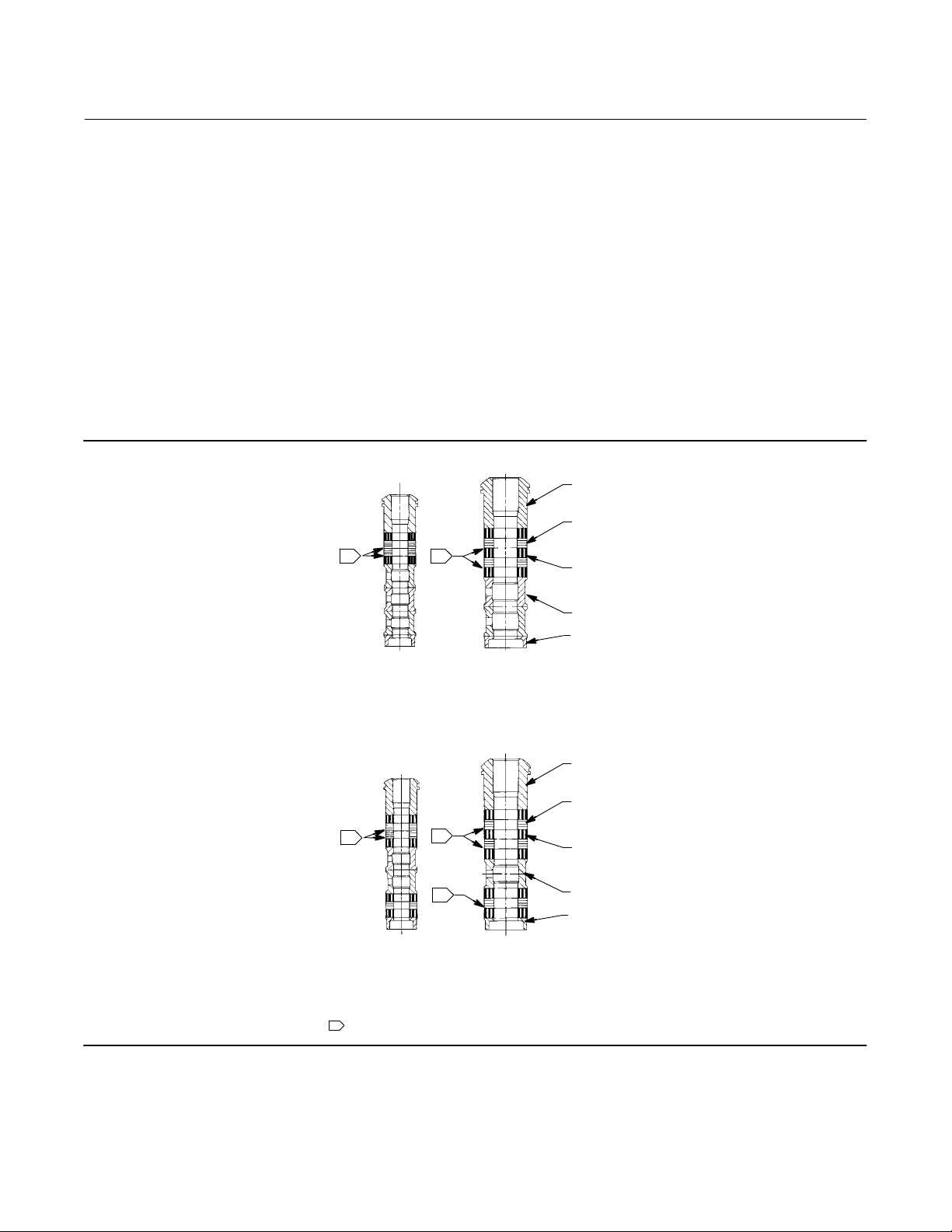
Figure 6. Detail of Graphite Ribbon/Filament Packing
PACKING
FOLLOWER
(KEY 13)
GRAPHITE
RIBBON
PACKING RING
1
13A9775-B
12.7 mm
(1/2 INCH)
STEM
1
13A9776-B
19.1, 25.4, & 31.8 mm
(3/4, 1 & 1‐1/4 INCH)
STEM
SINGLE ARRANGEMENTS
(KEY 7)
GRAPHITE
FILAMENT
PACKING RING
(KEY 7)
LANTERN
RING (KEY 8)
PACKING BOX
RING (KEY 11)
12
A6067
1
14A1849-B
12.7 mm
(1/2 INCH)
STEM
NOTES:
1
USE ONLY ONE BELOW EACH GRAPHITE RIBBON RING.
0.102 mm (0.004 INCH) THICK SACRIFICIAL ZINC WASHERS;
1
1
14A1780-B
19.1, 25.4, & 31.8 mm
(3/4, 1 & 1‐1/4 INCH)
STEM
DOUBLE ARRANGEMENTS
PACKING
FOLLOWER
(KEY 13)
GRAPHITE
GRAPHITE
RIBBON
RIBBON
PACKING RING
PACKING RING
(KEY 7)
(KEY 7)
GRAPHITE
FILAMENT
PACKING RING
(KEY 7)
LANTERN
RING (KEY 8)
PACKING BOX
RING (KEY 11)
Page 13

Instruction Manual
D100399X012
Note
Proper performance of the tightening procedures in step 11 compresses the spiral wound gasket (key 12, figure 22 through 23) or
load ring (key 26, figure 24) enough to both load and seal the seat ring gasket (key 13, figure 22, 23 or 24). It also compresses the
outer edge of the bonnet gasket (key 10, figure 22 through 24) enough to seal the body‐to‐bonnet joint.
The proper bolting procedures in step 11 include‐‐but are not limited to‐‐ensuring that bolting threads are clean, and evenly
tightening the nuts onto the studs in a criss‐cross pattern. Because of the bolt‐up characteristics of spiral wound gaskets,
tightening one nut may loosen an adjacent nut. Repeat the criss‐cross tightening pattern several times until each nut is tight and
the body‐to‐bonnet seal is made. When the operating temperature has been reached, perform this torquing procedure once
again.
Note
Stud(s) and nut(s) should be installed such that the manufacturer's trademark and material grade marking is visible, allowing easy
comparison to the materials selected and documented in the Emerson/Fisher serial card provided with this product.
EW Valve
July 2017
WARNING
Personal injury or damage to equipment could occur if improper stud and nut materials or parts are used. Do not operate or
assemble this product with stud(s) and nut(s) that are not approved by Emerson/Fisher engineering and/or listed on the
serial card provided with this product. Use of unapproved materials and parts could lead to stresses exceeding the design
or code limits intended for this particular service. Install studs with the material grade and manufacturer's identification
mark visible. Contact your Emerson Automation Solutions representative immediately if a discrepancy between actual
parts and approved parts is suspected.
11. Lubricate the bolting (not necessary if factory pre‐lubricated stud bolt nuts are used) and install it, using proper
bolting procedures during tightening so that the body‐to‐bonnet joint will withstand test pressures and application
service conditions. Use the bolt torques in table 5 as guidelines.
12. Install new packing and the metal packing box parts according to the appropriate arrangement in figure 4, 5, or 6.
Place a smooth‐edged pipe over the valve stem and gently tap each soft packing part into the packing box.
13. Slide the packing follower, upper wiper, and packing flange (keys 13, 12, and 3, figure 21) into position. Lubricate
the packing flange studs (key 4, figure 21) and the faces of the packing flange nuts (key 5, figure 21). Install the
packing flange nuts.
14. For spring‐loaded PTFE V‐ring packing, tighten the packing flange nuts until the shoulder on the packing follower
(key 13, figure 21) contacts the bonnet.
For graphite packing, tighten the packing flange nuts to the maximum recommended torque shown in table 6. Then,
loosen the packing flange nuts, and retighten them to the recommended minimum torque shown in table 6.
For ENVIRO‐SEAL or HIGH‐SEAL live‐loaded packing, refer to the note at the beginning of the Packing Maintenance
section.
For other packing types, tighten the packing flange nuts alternately in small equal increments until one of the nuts
reaches the minimum recommended torque shown in table. Then, tighten the remaining flange nuts until the packing
flange is level and at a 90‐degree angle to the valve stem.
15. Mount the actuator on the valve assembly, and reconnect the actuator and valve stem according to the procedure
in the appropriate actuator instruction manual.
13
Page 14
EW Valve
July 2017
Instruction Manual
D100399X012
Trim Maintenance
WARNING
Avoid personal injury or property damage from sudden release of process pressure. Before performing any maintenance
operations:
D Do not remove the actuator from the valve while the valve is still pressurized.
D Always wear protective gloves, clothing, and eyewear when performing any maintenance operations to avoid personal
injury.
D Disconnect any operating lines providing air pressure, electric power, or a control signal to the actuator. Be sure the
actuator cannot suddenly open or close the valve.
D Use bypass valves or completely shut off the process to isolate the valve from process pressure. Relieve process pressure
on both sides of the valve. Drain the process media from both sides of the valve.
D Vent the pneumatic actuator loading pressure and relieve any actuator spring precompression.
D Use lock‐out procedures to be sure that the above measures stay in effect while you work on the equipment.
D The valve packing box may contain process fluids that are pressurized, even when the valve has been removed from the
pipeline. Process fluids may spray out under pressure when removing the packing hardware or packing rings, or when
loosening the packing box pipe plug.
D Check with your process or safety engineer for any additional measures that must be taken to protect against process
media.
Table 5. Body‐to‐Bonnet Bolt Torque Guidelines
VALVE SIZE, NPS
4x2 102 75
6x4 or 8x4 259 191
8x6
10x8 745 550
12x6 548 404
12x8
1. Determined from laboratory tests.
2. For other materials, contact your Emerson sales office
CL300 or CL600 548 404
CL900 1315 970
CL300 or CL600 732 540
CL900 2712 2000
or Local Business Partner for torques.
NSm LbfSft
BOLT TORQUES
(1, 2)
Table 6. Recommended Torque for Packing Flange Nuts
VALVE STEM
DIAMETER
mm Inches NSm LbfSIn NSm LbfSIn NSm LbfSIn NSm LbfSIn
12.7
12.7 CL600 9 81 14 122 4 39 7 58
19.1
19.1 CL600 21 182 31 274 10 87 15 131
25.4
25.4 CL600 35 310 53 466 17 149 25 223
31.8
31.8 CL600 49 437 74 655 24 209 36 314
1/2
3/4
1
1‐1/4
PRESSURE
RATING
CL300 7 59 10 88 3 28 5 42
CL300 15 133 23 199 7 64 11 95
CL300 26 226 38 339 12 108 18 162
CL300 36 318 54 477 17 152 26 228
Minimum Torque Maximum Torque Minimum Torque Maximum Torque
GRAPHITE TYPE PACKING PTFE TYPE PACKING
14
Page 15

Instruction Manual
D100399X012
EW Valve
July 2017
CAUTION
In the following applicable procedures, to avoid damaging parts, do not grip the bellows shroud or other parts of the
stem/bellows assembly. Grip only the flat areas on the stem where it extends out of the top of the bellows shroud.
For C‐seal construction, see the appropriate C‐seal sections in this instruction manual.
Except where indicated, key numbers in this section are referenced in figure 22 for EWD constructions, figure 22 for
restricted trim detail, figure 23 for EWS constructions, and figure 24 for EWT constructions. Refer to figures 26 and 27
for Cavitrol III, figure 27 for Whisper Trim III, and figure 29 for WhisperFlo construction.
Trim Removal
1. Remove the actuator and the bonnet according to steps 1 through 5 of the Replacing Packing procedure.
WARNING
Avoid personal injury or property damage from valve or packing leakage.
When lifting the valve plug stem (key 7) and attached valve plug (key 2) out of the valve, be certain that the cage (key 3)
remains in the valve (key 1). This will prevent cage damage that might be caused by the cage dropping back into the valve
after being lifted part way out.
Use care to avoid damaging gasket sealing surfaces.
Each graphite piston ring (key 6) in an EWD valve is brittle and in two pieces. Use care to avoid damage to the piston ring(s)
caused by dropping or rough handling.
Any damage to the gasket sealing surfaces could cause the valve to leak. The surface finish of the valve stem (key 7) is
critical for making a good packing seal. The inside surface of the cage or cage/baffle assembly (key 3) or cage retainer (key
31) is critical for smooth operation of the valve plug and for making a seal with the piston ring (key 6) or seal ring (key 28).
The seating surfaces of the valve plug (key 2) and the seat ring (key 9) on a metal‐seat construction are critical for tight
shutoff. Protect these parts accordingly while disassembling the trim.
2. Remove the packing flange nuts, packing flange, upper wiper, and packing follower (keys 5, 3, 24, and 25, figure
21). Carefully push out all the remaining packing parts from the valve side of the bonnet using a rounded rod or
other tool that will not scratch the packing box wall. Clean the packing box and the metal packing parts.
3. Inspect the valve stem threads and packing box surfaces for any sharp edges which might cut the packing.
Scratches or burrs could cause packing box leakage or damage to the new packing. If the surface condition cannot
be improved by light sanding, replace the damaged parts.
4. Remove the load ring (key 26) from an NPS 10x8 or 12x8 valve or the cage adaptor (key 4) from any restricted‐trim
valve through NPS 8x4, and wrap it for protection.
5. On a 102 mm (4‐inch) travel valve with Whisper Trim I cage or on any NPS 8x6 or 12x6 valve with Whisper Trim III
cage, remove the bonnet spacer (key 32) and bonnet gasket (key 10) on top of the spacer. Then on any
construction with a cage retainer (key 31), remove the cage retainer and its associated gaskets. A Whisper Trim III
cage retainer has two 3/8‐inch ‐ 16 UNC tappings in which screws or bolts can be installed for lifting.
6. Remove the cage or cage/baffle assembly (key 3) and the associated gaskets (keys 10, 11, and 12). With
full‐capacity constructions that have FGM gasket sets, a shim (key 53) is used instead of the cage gasket (key 11). If
the cage is stuck in the valve, use a rubber mallet to strike the exposed portion of the cage at several points around
its circumference.
15
Page 16
EW Valve
July 2017
Figure 7. TSO (Tight Shutoff Trim), Detail of Protected Soft Seat
INNER PLUG
PROTECTED SOFT SEAT
SEAT RING
A7088
Instruction Manual
D100399X012
OUTER PLUG
CAGE
7. For constructions other than TSO (tight shutoff trim), remove the seat ring (key 9) or disk seat (key 22), seat ring
gasket (key 13), and the seat ring adaptor (key 5) and adaptor gasket (key 14) where used in a restricted‐capacity
construction. EWS and EWT PTFE‐seat constructions use a disk (key 23) sandwiched between the disk seat and disk
retainer (key 21). A CL900 NPS 8x6 EWT construction with Cavitrol III cage has its spiral wound gasket (key 12) on
the side of the seat ring opposite the seat ring gasket.
8. For TSO (tight shutoff trim) constructions, perform the following steps (refer to figures 7 and 8):
D Remove the piston ring, anti‐extrusion rings, backup ring, and retainer.
D Remove the set screws that lock the outer plug to the inner plug.
D Using a strap wrench or similar tool, unscrew the outer plug from the inner plug. Do not damage the outer plug
guide surfaces.
D Remove the protected soft seat seal.
D Inspect the parts for damage and replace if needed.
9. For all constructions, inspect parts for wear or damage that would prevent proper operation of the valve. Replace or
repair trim parts according to the following procedures for lapping metal seats or other valve plug maintenance
procedures, as appropriate.
Lapping Metal Seats
CAUTION
To avoid damaging the ENVIRO‐SEAL bellows seal bonnet assembly, do not attempt to lap the metal seating surfaces. The
design of the assembly prevents rotation of the stem and any forced rotation will damage internal components of the
ENVIRO‐SEAL bellows seal bonnet.
16
Page 17

Instruction Manual
D100399X012
Figure 8. Typical Balanced TSO Trim
EW Valve
July 2017
VALVE PLUG
SEAL
A7096
PROTECTED
SOFT SEAT
Except with respect to the ENVIRO‐SEAL Bellows Seal Bonnet assembly, with metal seat constructions, seating surfaces
of the valve plug and seat ring (keys 2 and 9, figures 24 through 26) can be lapped for improved shutoff. (Deep nicks
should be machined out rather than ground out.) Use a good quality lapping compound of a mixture of 280 to
600‐grit. Apply the compound to the bottom of the valve plug.
Assemble the valve to the extent that the cage (and cage retainer and bonnet spacer, if used) is in place and the
bonnet is bolted to the valve. A simple handle can be made from a piece of strap iron locked to the valve plug stem
with nuts. Rotate the handle alternately in each direction to lap the seats. After lapping, remove the bonnet, and clean
the seat surfaces. Completely assemble the valve as described in the Trim Replacement portion of the Trim
Maintenance section, and test the valve for shutoff. Repeat the lapping procedure if leakage is still excessive.
Valve Plug Maintenance
Except where indicated, key numbers in this section are referenced in figure 22 for EWD valve plugs, figure 23 for EWS
valve plugs, and figure 24 for EWT valve plugs.
CAUTION
If replacing the piston ring (key 6) or seal ring (key 28), be careful not to scratch the surfaces of the ring groove in the valve
plug or any of the surfaces of the replacement ring, or the replacement ring may not seal properly.
1. With the valve plug (key 2) removed, according to the Trim Removal section, proceed as appropriate:
17
Page 18

EW Valve
July 2017
Instruction Manual
D100399X012
For the EWD carbon‐filled PTFE piston ring, the ring is split in one place. If there is visible damage, spread the ring
slightly, and remove it from the groove in the valve plug. To install a carbon‐filled PTFE piston ring, spread the ring
apart slightly at the split, and install it over the stem and into the groove in the valve plug. The open side must face
along the stem, depending on flow direction, as shown in figure 22.
For each EWD graphite piston ring, the ring can be easily removed since it is in two pieces. A new graphite piston ring is
furnished as a complete ring. Use a vise with smooth or taped jaws to break this replacement ring into halves. Place the
new ring in the vise so that the jaws will compress the ring into an oval. Slowly compress the ring until it snaps on both
sides. If one side snaps first, do not try to tear or cut the other side. Instead, keep compressing the ring until the other
side snaps. Be sure to match the broken ends when installing the ring in the valve plug groove.
For the EWT two‐piece seal ring, the ring cannot be reused as it is a closed ring, which must be pried and/or cut from
the groove. Then the elastomeric backup ring (key 29) can be spread slightly and removed.
To install a new two‐piece seal ring, apply a general purpose silicone‐base lubricant to both the backup ring and seal
ring (keys 29 and 28). Place the backup ring over the stem (key 7) and into the groove. Place the seal ring over the top
edge of the valve plug (key 2) so that it enters the groove on one side of the valve plug. Slowly and gently stretch the
seal ring, and work it over the top edge of the valve plug. The PTFE material in the seal ring must be permitted time to
cold‐flow during the stretching procedure; so avoid jerking sharply on this ring. Stretching the seal ring over the valve
plug may make it seem unduly loose when in the groove, but it will contract to its original size after insertion into the
cage.
For the EWT spring‐loaded seal ring, the ring used on a valve plug having a 136.5 mm (5.375 inch) or less port
diameter may be removed undamaged by first working the retaining ring (key 27) off with a screwdriver. Then
carefully slide the metal backup ring (key 29) and seal ring (key 28) off the valve plug (key 2). The spring‐loaded seal
ring used on a valve plug having a 178 mm (7‐inch) or greater port diameter must be carefully pried and/or cut from its
groove. Therefore, it cannot be reused.
A spring‐loaded seal ring must be installed so that its open side faces toward either the top or the bottom of the valve
plug, depending on flow direction, as shown in view A of figure 24. To install a spring‐loaded seal ring on a valve plug
with a 136.5 mm (5.375 inch) or less port diameter, slide the seal ring (key 28) onto the valve plug followed by the
metal backup ring (key 29). Then install the retaining ring (key 27) by inserting one end in the groove and, while
turning the plug, press the ring into the groove. Again, be careful not to scratch any surfaces of the ring or plug.
To install the seal ring on a valve plug with 178 mm (7‐inch) or greater port diameter, lubricate it with a general
purpose silicone‐base lubricant. Then gently stretch the seal ring, and work it over the top edge of the valve plug. The
PTFE material in the seal ring must be permitted time to cold‐flow during the stretching procedure; so avoid jerking
sharply on the ring. Stretching the seal ring over the valve plug may make it seem unduly loose when in the groove,
but it will contract to its original size after insertion into the cage.
CAUTION
Never reuse an old stem or adaptor with a new valve plug. Using an old stem or adaptor with a new plug requires drilling a
new pin hole in the stem (or adaptor in case an ENVIRO‐SEAL bellows seal bonnet is being used). This drilling weakens the
stem or adaptor and may cause failure in service. However, a used valve plug may be reused with a new stem or adaptor
except with Cavitrol III trim.
Note
The valve plug and valve plug stem for Cavitrol III trim are a matched set and must be ordered together. If the Cavitrol III valve plug
or valve plug stem is damaged, replace the entire assembly (key 2, figure 26 and 27).
2. To replace the valve stem (key 7), drive out the pin (key 8). Unscrew the valve plug from the stem or adaptor.
18
Page 19

Instruction Manual
D100399X012
EW Valve
July 2017
3. To replace the adaptor (key 24, figure 21) on ENVIRO‐SEAL bellows seal bonnets, place the plug stem assembly and
valve plug in a soft‐jaw chuck or other type of vise so that the jaws grip a portion of the valve plug that is not a
seating surface. Drive out the pin (key 36, figure 21). Reverse the plug stem assembly and valve plug in the soft‐jaw
chuck or vise. Grip the flat areas on the valve stem just below the threads for the actuator/stem connection.
Unscrew the valve plug/adaptor assembly (key 24, figure 21) from the valve stem assembly (key 20, figure 21).
4. Screw the new stem or adaptor into the valve plug. Tighten to the torque value given in table 7. Refer to table 7 to
select the proper drill size. Drill through the stem or adaptor, using the hole in the valve plug as a guide. Remove
any chips or burrs, and drive in a new pin to lock the assembly.
5. For ENVIRO‐SEAL bellows seal bonnets, grip the flats of the stem extending out of the top of the bellows shroud
with a soft‐jaw chuck or other type of vise. Screw the valve plug/adaptor assembly onto the valve stem. Tighten as
necessary to align the pin hole in the stem with one of the holes in the adaptor. Secure the adaptor to the stem with
a new pin.
Trim Replacement
Except where indicated, key numbers in this section are referenced in figure 22 for EWD constructions, figure 22 for
restricted trim detail, figure 23 for EWS construction, and figure 24 for EWT constructions. Refer to figures 26 and 27
for Cavitrol III, figure 28 for Whisper Trim III, and figure 29 for WhisperFlo constructions.
1. With a restricted‐trim seat ring construction, install the adaptor gasket (key 14) and seat ring adaptor (key 5).
2. Install the seat‐ring gasket (key 13), seat ring (key 9), or disk seat (key 22). With a PTFE‐seat construction install the
disk and disk retainer (keys 21 and 23). With an NPS 8x6 CL900 EWT valve with Cavitrol III cage, install the spiral
wound gasket (key 12) on the seat ring.
3. Install the cage or cage/baffle assembly (key 3). Any rotational orientation of the cage or assembly with respect to
the valve is acceptable. A Whisper Trim III cage designated by level A3, B3, or C3 may be installed with either end
up. The level D3 cage/baffle assembly or Cavitrol III cage assembly, however, must be installed with the hole pattern
end next to the seat ring. If a cage retainer (key 31) is to be used, place it on top of the cage.
4. For constructions other than TSO (tight shutoff trim), slide the valve plug (key 2) and stem assembly or valve plug
and ENVIRO‐SEAL bellows seal assembly into the cage. Make sure the piston ring or seal ring (key 6 or 28) is evenly
engaged in the entrance chamfer at the top of the cage (key 3) or cage retainer (key 31) to avoid damaging the ring.
5. For TSO (tight shutoff) trim constructions, perform the following steps (refer to figures 7 and 8).
D Thread the outer plug onto the inner plug until the parts seat metal to metal, using a strap wrench or similar tool
that will not damage the outer plug guide surfaces.
D Mark the top of the inner plug and outer plug with alignment marks in the assembled position.
Table 7. Valve Stem to Plug Torque and Pin Replacement Data
VALVE STEM DIAMETER STEM TORQUE, MINIMUM TO MAXIMUM
mm Inch NSm LbfSft
12.7 1/2 81 to 115 60 to 85 1/8
19.1 3/4 237 to 339 175 to 250 3/16
25.4 1 420 to 481 310 to 355 1/4
31.8 1‐1/4 827 to 908 610 to 670 1/4
DRILL SIZE, INCHES
D Disassemble the outer plug from the inner plug and install the seal over the inner plug, so that the seal rests below
the threaded area.
D Thread the outer plug onto the inner plug and tighten with a strap wrench or similar tool until the alignment marks
line up. This will ensure that the plug parts are metal to metal and the seal is compressed properly. Do not damage
the outer plug guide surfaces.
D Install set screws centering the inner plug in the outer plug and torque to 11 NSm (8 lbfSft).
19
Page 20

EW Valve
July 2017
Instruction Manual
D100399X012
D Assemble the piston ring, anti‐extrusion rings, backup ring, and retainer.
6. For all constructions, place the gaskets (keys 12, 11 or 14 if used, and 10) and the shim, if used (key 53), on top of
the cage or cage retainer. If there is a cage adaptor (key 4) or a bonnet spacer (key 32), set it on the cage or cage
retainer gaskets and place another flat sheet gasket (key 10) on top of the adapter or spacer. If there is only a cage
retainer or bonnet spacer, place another flat sheet gasket on the retainer or spacer.
7. With an NPS 10x8 or 12x8 valve, install the load ring (key 26).
8. Mount the bonnet on the valve, and complete assembly according to steps 11 through 15 of the Replacing Packing
section. Be sure to observe the note prior to step 11.
Retrofit: Installing C‐seal Trim
Note
Additional actuator thrust is required for a valve with C‐seal trim. When installing C‐seal trim in an existing valve, contact your
Emerson sales office
Assemble the new valve plug/retainer assembly (with C‐seal plug seal) using the following instructions:
or Local Business Partner for assistance in determining new actuator thrust requirements.
CAUTION
To avoid leakage when the valve is returned to service, use appropriate methods and materials to protect all sealing
surfaces of the new trim parts while assembling the individual parts and during installation in the valve body.
1. Apply a suitable high‐temperature lubricant to the inside diameter of the C‐seal plug seal. Also, lubricate the
outside diameter of the valve plug where the C‐seal plug seal must be pressed into the proper sealing position
(figure 9).
2. Orient the C‐seal plug seal for correct sealing action based on the process fluid flow direction through the valve.
D The open interior of the C‐seal plug seal must face up in a valve with flow‐up construction (figure 9).
D The open interior of the C‐seal plug seal must face down in a valve with flow‐down construction (figure 9).
Note
An installation tool must be used to properly position the C‐seal plug seal on the valve plug. A tool is available as a spare part from
Emerson or a tool could be manufactured following the dimensions given in figure 10.
3. Place the C‐seal plug seal over the top of the valve plug and press the C‐seal plug seal onto the plug using the C‐seal
installation tool. Carefully press the C‐seal plug seal onto the plug until the installation tool contacts the horizontal
reference surface of the valve plug (figure 11).
4. Apply a suitable high‐temperature lubricant to the threads on the plug. Then, place the C‐seal retainer onto the
plug and tighten the retainer using an appropriate tool such as a strap wrench.
5. Using an appropriate tool such as a center punch, stake the threads on top of the plug in one place (figure 12) to
secure the C‐seal retainer.
20
Page 21

Instruction Manual
D100399X012
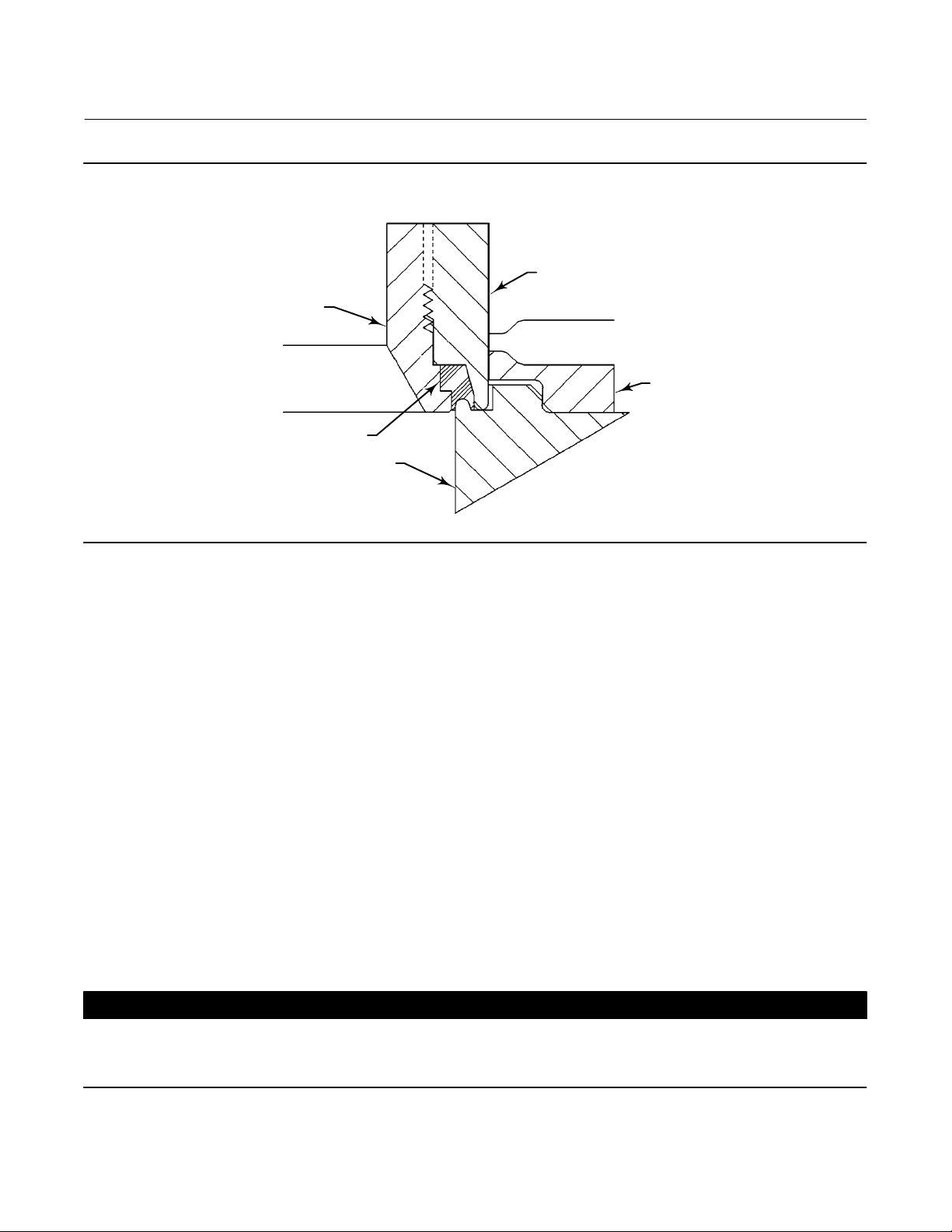
Figure 9. Fisher EWD with C‐seal Trim
EW Valve
July 2017
64 64
FLOW DOWN
VIEW A
FLOW UP
7
8
65
64
A
2
A6790
6. Install the new plug/retainer assembly with C‐seal plug seal on the new stem following the appropriate instructions
in the Trim Replacement section of this manual.
7. Install piston rings by following instructions in the Trim Replacement section of this manual.
8. Remove the existing valve actuator and bonnet following the appropriate instructions in the Replacing Packing
section in this manual.
9
CAUTION
Do not remove the existing valve stem from the valve plug unless you are planning to replace the valve stem.
Never reuse an old valve stem with a new plug or reinstall a valve stem after it has been removed. Replacing a valve stem
requires drilling a new pin hole in the stem. This drilling weakens the stem and may cause failure in service. However, a
used valve plug may be reused with a new valve stem.
9. Remove the existing valve stem and plug, cage, and seat ring from the valve body following the appropriate
instructions in the Trim Removal section in this manual.
10. Replace all gaskets according to appropriate instructions in the Trim Replacement section in this manual.
11. Install the new seat ring, cage, valve plug/retainer assembly, and stem into the valve body and completely
reassemble the valve package following the appropriate instructions in the Trim Replacement section in this
manual.
21
Page 22

EW Valve
July 2017
Instruction Manual
D100399X012
FOR VALVE
PLUGS
FITTING
PORT SIZE
(Inches)
2.875 82.55
3.4375 101.6
3.625 104.394
4.375 125.984
5.375 142.748
7 184.15
8 209.55
FOR VALVE
PLUGS
FITTING
PORT SIZE
(Inches)
A B C D E F G H
52.324 ‐
52.578
58.674 ‐
58.928
65.024 ‐
65.278
83.439 ‐
83.693
100.076 ‐
100.33
141.376 ‐
141.630
166.776 ‐
167.030
4.978 ‐ 5.029 3.708 ‐ 3.759 41.148
4.978 ‐ 5.029 3.708 ‐ 3.759 50.8
4.978 ‐ 5.029 3.708 ‐ 3.759 50.8
4.978 ‐ 5.029 3.708 ‐ 3.759 50.8
4.978 ‐ 5.029 3.708 ‐ 3.759 45.974
4.978 ‐ 5.029 3.708 ‐ 3.759 60.198
4.978 ‐ 5.029 3.708 ‐ 3.759 55.88
A B C D E F G H
DIMENSIONS, mm
(See Drawing Below)
DIMENSIONS, INCHES
(See Drawing Below)
52.680 ‐
52.781
61.011 ‐
61.112
68.936 ‐
69.037
87.351 ‐
87.452
103.835 ‐
103.937
145.136 ‐
145.237
170.536 ‐
170.637
55.118 ‐
55.626
63.449 ‐
63.957
71.374 ‐
71.882
89.789 ‐
90.297
106.274 ‐
106.782
147.574 ‐
148.082
172.974 ‐
173.482
Part Number
(To Order
A Tool)
70.891 ‐ 71.044 24B9816X012
85.166 ‐ 85.319 24B5612X012
89.941 ‐ 90.094 24B3630X012
108.991 ‐ 109.144 24B3635X012
128.219 ‐ 128.372 23B9193X012
169.520 ‐ 169.672 23B9180X012
194.920 ‐ 195.072 24B9856X012
Part Number
(To Order
A Tool)
2.875 3.25 2.060 ‐ 2.070 0.196 ‐ 0.198 0.146 ‐ 0.148 1.62 2.074 ‐ 2.078 2.170 ‐ 2.190 2.791 ‐ 2.797 24B9816X012
3.4375 4.00 2.310 ‐ 2.320 0.196 ‐ 0.198 0.146 ‐ 0.148 2.00 2.402 ‐ 2.406 2.498 ‐ 2.518 3.353 ‐ 3.359 24B5612X012
3.625 4.11 2.560 ‐ 2.570 0.196 ‐ 0.198 0.146 ‐ 0.148 2.00 2.714 ‐ 2.718 2.810 ‐ 2.830 3.541 ‐ 3.547 24B3630X012
4.375 4.96 3.285 ‐ 3.295 0.196 ‐ 0.198 0.146 ‐ 0.148 2.00 3.439 ‐ 3.443 3.535 ‐ 3.555 4.291 ‐ 4.297 24B3635X012
5.375 5.62 3.940 ‐ 3.950 0.196 ‐ 0.198 0.146 ‐ 0.148 1.81 4.088 ‐ 4.092 4.184 ‐ 4.204 5.048 ‐ 5.054 23B9193X012
7 7.25 5.566 ‐ 5.576 0.196 ‐ 0.198 0.146 ‐ 0.148 2.37 5.714 ‐ 5.718 5.810 ‐ 5.830 6.674 ‐ 6.680 23B9180X012
8 8.25 6.566 ‐ 6.576 0.196 ‐ 0.198 0.146 ‐ 0.148 2.20 6.714 ‐ 6.718 6.810 ‐ 6.830 7.674 ‐ 7.680 24B9856X012
Figure 10. C‐seal Plug Seal Installation Tool
45° X 0.06
8° - 9°
C
D
A6777
∅A
∅B
∅F
∅G
∅H
E
45° X 0.02
BREAK SHARP
CORNER
45° X 0.01 MAX
22
Page 23

Instruction Manual
D100399X012
Figure 11. Installing the C‐seal Plug Seal Using the Installation Tool
INSTALLATION
TOOL
C‐SEAL
METAL
PLUG
SEAL
EW Valve
July 2017
VALVE
PLUG
HORIZONTAL
REFERENCE
SURFACE
NOTE:
PRESS INSTALLATION TOOL OVER VALVE PLUG UNTIL THE TOOL CONTACTS THE
A6778
HORIZONTAL REFERENCE SURFACE OF THE VALVE PLUG.
Figure 12. Stake the Threads of the C‐seal Retainer
DEFORM THREAD TO
STAKE C‐SEAL RETAINER
PISTON
RING
RETAINER
C‐SEAL
METAL
PLUG
SEAL
FLOW DOWN
VALVE
PLUG
A6779
FLOW DOWN
23
Page 24

EW Valve
July 2017
Instruction Manual
D100399X012
CAUTION
To avoid excessive leakage and seat erosion, the valve plug must be initially seated with sufficient force to overcome the
resistance of the C‐seal plug seal and contact the seat ring. You can correctly seat the valve plug by applying the full
actuator load. This force will adequately drive the valve plug to the seat ring, thus giving the C‐seal plug seal a
predetermined permanent set. Once this is done, the plug/retainer assembly, the cage, and the seat ring become a
matched set.
With full actuator force applied and the valve plug fully seated, align the actuator travel indicator scale with the lower end
of valve travel. Refer to the appropriate actuator instruction manual for information on this procedure.
Replacement of Installed C‐seal Trim
Trim Removal (C‐seal Constructions)
1. Remove the valve actuator and bonnet following the appropriate instructions in the Replacing Packing section in
this manual.
CAUTION
To avoid leakage when the valve is returned to service, use appropriate methods and materials to protect all sealing
surfaces of the trim parts during maintenance.
Use caution when removing piston ring(s) and C‐seal plug seal to avoid scratching any sealing surface.
CAUTION
Do not remove the valve stem from the plug/retainer assembly unless you are planning to replace the valve stem.
Never reuse an old valve stem with a new plug or reinstall a valve stem after it has been removed. Replacing a valve stem
requires drilling a new pin hole in the stem. This drilling weakens the stem and may cause failure in service. However, a
used valve plug may be reused with a new valve stem.
2. Remove the plug/retainer assembly (with C‐seal plug seal), cage, and seat ring from the valve body following the
appropriate instructions in the Trim Removal section of this manual.
3. Locate the staked thread on top of the valve plug (figure 12). The staked thread secures the retainer. Use a drill with
a 1/8 inch bit to drill out the staked area of the thread. Drill approximately 1/8 inch into the metal to remove the
staking.
4. Locate the break between sections of the piston ring(s). Using an appropriate tool such as a flat‐blade screwdriver,
carefully pry out the piston ring(s) from the groove(s) in the C‐seal retainer.
5. After removing the piston ring(s), locate the 1/4‐inch diameter hole in the groove. In a retainer with two piston ring
grooves, the hole will be found in the upper groove.
6. Select an appropriate tool such as a punch and place the tip of the tool into the hole with the body of the tool held
tangent to the outside diameter of the retainer. Strike the tool with a hammer to rotate the retainer and free it from
the valve plug. Remove the retainer from the plug.
7. Use an appropriate tool such as a flat‐blade screwdriver to pry the C‐seal plug seal off the plug. Use caution to avoid
scratches or other damage to the sealing surfaces where the C‐seal plug seal makes contact with the valve plug
(figure 13).
24
Page 25

Instruction Manual
D100399X012
Figure 13. Lower (Valve Plug to Seat Ring) and Upper (C‐seal Plug Seal to Cage) Seating Surfaces
RETAINER
C‐seal METAL
PLUG SEAL
1
VALVE PLUG
UPPER SEATING SURFACE
PLUG
CAGE
CAGE
EW Valve
July 2017
SEAT
NOTE:
UPPER SEATING SURFACE IS THE AREA OF CONTACT BETWEEN
1
THE C‐seal METAL PLUG SEAL AND THE CAGE.
A6780
LOWER SEATING SURFACE
RING
8. Inspect the lower seating surface where the valve plug contacts the seat ring for wear or damage which would
prevent proper operation of the valve. Also, inspect the upper seating surface inside the cage where the C‐seal plug
seal contacts the cage, and inspect the sealing surface where the C‐seal plug seal makes contact with the plug
(figure 13).
9. Replace or repair trim parts according to the following procedure for lapping metal seats, remachining metal seats,
or other valve plug maintenance procedures as appropriate.
Lapping Metal Seats (C‐seal Constructions)
Before installing a new C‐seal plug seal, lap the lower seating surface (valve plug to seat ring,
figure 13) following appropriate procedures in the Lapping Metal Seats section of this manual.
Remachining Metal Seats (C‐seal Constructions)
See figure 14. A valve plug with a C‐seal metal plug seal features two seating surfaces. One seating surface is found
where the valve plug contacts the seat ring. The second seating surface is found where the C‐seal plug seal contacts
the upper seating surface in the cage. If you machine the seats on the seat ring and/or plug, you must machine an
equal dimension from the seating area in the cage.
CAUTION
If metal is removed from the seat ring and plug and a corresponding amount is not removed from the cage seating area, the
C‐seal plug seal will be crushed as the valve closes and the C‐seal retainer will strike the seating area of the cage, preventing
the valve from closing.
25
Page 26
EW Valve
July 2017
Instruction Manual
D100399X012
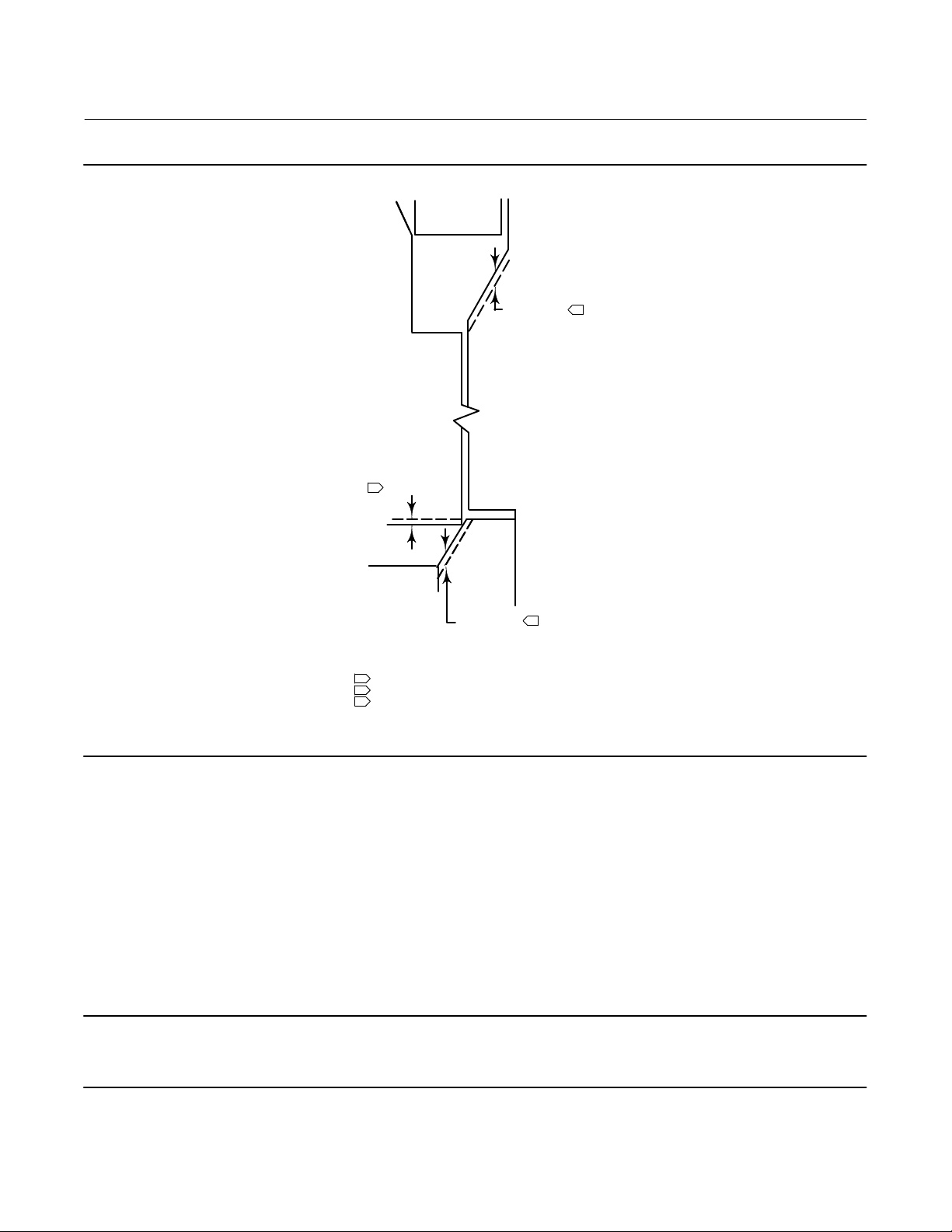
Figure 14. Example of Machining the Lower (Valve Plug to Seat Ring) and Upper (C‐seal Plug Seal to Cage) Seating
Surfaces
1
PLUG
0.254 (0.010)
C‐seal
RETAINER
(4)
UPPER SEATING
SURFACE
(4)
0.508 (0.020)
MACHINING OF THE UPPER
SEATING SURFACE MUST
EQUAL THE TOTAL MACHINING OF
THE LOWER SEATING SURFACE
(PLUG PLUS SEAT RING). IF NOT, THE
RETAINER MAY STRIKE THE UPPER
SEATING SURFACE BEFORE THE
VALVE PLUG PROPERLY SEATS ON
THE LOWER SEATING SURFACE.
3
CAGE
SEAT
RING
(4)
0.254 (0.010)
2
LOWER SEATING SURFACE
NOTE:
PLUS
A6781 / IL
REMOVAL OF 0.254 mm (0.010 inch) FROM THE VALVE PLUG
1
REMOVAL OF 0.254 mm (0.010 inch) FROM THE SEAT RING
2
3
REMOVAL OF 0.508 mm (0.020 inch) FROM THE UPPER
SEATING SURFACE IN THE CAGE
4. THESE VALUES ARE FOR EXAMPLE ONLY. REMOVE ONLY THE MINI
MUM AMOUNT OF MATERIAL REQUIRED TO REFURBISH THE SEATS.
Trim Replacement (C‐seal Constructions)
1. Apply a suitable high‐temperature lubricant to the inside diameter of the C‐seal plug seal. Also, lubricate the
outside diameter of the valve plug where the C‐seal plug seal must be pressed into the proper sealing position
(figure 9).
2. Orient the C‐seal plug seal for correct sealing action based on the process fluid flow direction through the valve.
D The open interior of the C‐seal plug seal must face up in a valve with flow‐up construction (figure 9).
D The open interior of the C‐seal plug seal must face down in a valve with flow‐down construction (figure 9).
Note
An installation tool must be used to properly position the C‐seal plug seal on the valve plug. A tool is available as a spare part from
Emerson or a tool could be manufactured following the dimensions given in figure 10.
26
Page 27

Instruction Manual
D100399X012
EW Valve
July 2017
3. Place the C‐seal plug seal over the top of the valve plug and press it onto the plug using the installation tool.
Carefully press the C‐seal plug seal onto the plug until the installation tool contacts the horizontal reference surface
of the valve plug (figure 11).
4. Apply a suitable high‐temperature lubricant to the threads on the plug. Then, place the C‐seal retainer onto the
plug and tighten the retainer using an appropriate tool such as a strap wrench.
5. Using an appropriate tool such as a center punch, stake the threads on top of the plug in one place (figure 12) to
secure the C‐seal retainer.
6. Replace the piston ring(s) following instructions in the Trim Replacement section of this manual.
7. Return the seat ring, cage, plug/retainer assembly, and stem to the valve body and completely reassemble the valve
package following the appropriate instructions in the Trim Replacement section of this manual.
CAUTION
To avoid excessive leakage and seat erosion, the valve plug must be initially seated with sufficient force to overcome the
resistance of the C‐seal plug seal and contact the seat ring. You can correctly seat the valve plug by applying the full
actuator load. This force will adequately drive the valve plug to the seat ring, thus giving the C‐seal plug seal a
predetermined permanent set. Once this is done, the plug/retainer assembly, the cage, and the seat ring become a
matched set.
With full actuator force applied and the valve plug fully seated, align the actuator travel indicator scale with the lower end
of valve travel. Refer to the appropriate actuator instruction manual for information on this procedure.
ENVIRO‐SEAL Bellows Seal Bonnet
Replacing a Plain or Extension Bonnet with an ENVIRO‐SEAL Bellows Seal Bonnet
(Stem/Bellows Assembly)
Except where indicated, key numbers in this section are referenced in figure 22 for EWD constructions, figure 22 for
restricted trim detail, figure 23 for EWS constructions, and figure 24 for EWT constructions. Refer to figures 26 and 27
for Cavitrol III, figure 27 for Whisper Trim III, and figure 29 for WhisperFlo constructions.
Table 8. Recommended Torque for ENVIRO‐SEAL Bellows Seal Bonnet Packing Flange Nuts
VALVE SIZE,
NPS
4x2 1/2 2 22 4 33
6x4 to 12x8 1 5 44 8 67
VALVE STEM
DIAMETER THROUGH
PACKING
1. Remove the actuator and bonnet according to steps 1 through 6 of the Replacing Packing procedure in the
Maintenance section.
2. Lift out the cage.
3. Remove and discard the existing bonnet gasket. Cover the valve body opening to protect sealing surfaces and to
prevent foreign material from entering the valve body cavity.
Note
The ENVIRO‐SEAL stem/bellows assembly for easy-et valves is available only with a threaded and drilled plug/adaptor/stem
connection. The existing valve plug can be reused with the new stem/bellows assembly or a new plug can be installed.
MINIMUM TORQUE MAXIMUM TORQUE
NSm LbfSin NSm LbfSin
27
Page 28

EW Valve
July 2017
Instruction Manual
D100399X012
4. Inspect the existing valve plug. If the plug is in good condition, it can be reused with the new ENVIRO‐SEAL
stem/bellows assembly. To remove the existing valve plug from the stem, first, place the existing plug stem
assembly in a soft‐jaw chuck or other type of vise so that the jaws grip a portion of the valve plug that is not a
seating surface. Drive out or drill out the pin (key 8).
5. Then, reverse the plug stem assembly in the soft‐jaw chuck or vise. Grip the valve stem in an appropriate place and
unscrew the existing plug from the valve stem.
CAUTION
When installing a valve plug on the ENVIRO‐SEAL stem/bellows assembly, the valve stem must not be rotated. Damage to
the bellows may result.
Do not grip the bellows shroud or other parts of the stem/bellows assembly. Grip only the flat areas on the stem where it
extends out of the top of the bellows shroud.
Note
The ENVIRO‐SEAL stem/bellows assembly has a one‐piece stem.
6. To attach the valve plug to the stem of the new ENVIRO‐SEAL stem/bellows assembly, it is necessary to first attach
the plug to the adaptor (key 24, figure 21). Locate the adaptor. Notice that a hole has not been drilled in the threads
where the plug screws onto the adaptor. Secure the valve plug in a soft‐jaw chuck or other type of vise. Do not grip
the plug on any seating surface. Position the plug in the chuck or vise for easy threading of the adaptor. Thread the
adaptor into the valve plug and tighten to the appropriate torque value.
7. Select the proper size of drill bit and drill through the adaptor using the hole in the valve plug as a guide. Remove
any metal chips or burrs and drive in a new pin (key 8) to lock the plug/adaptor assembly together.
8. Attach the plug/adaptor assembly to the ENVIRO‐SEAL stem/bellows assembly by first securing the stem/bellows
assembly in a soft‐jaw chuck or other type of vise so that the jaws of the chuck or vise grip the flats of the stem
extending out of the top of the bellows shroud. Screw the valve plug/adaptor assembly onto the valve stem.
Tighten the plug/adaptor assembly until it is snug. Then turn the plug/adaptor assembly to the next pin hole in the
valve stem. Drive in new pin (key 36, figure 21) to lock the assembly.
9. Inspect the seat ring (key 9). Replace, if necessary.
10. Place a new gasket (key 10) into the valve body in place of the bonnet gasket. Install the new stem/bellows
assembly with valve plug/adaptor by placing it into the valve body on top of the new bellows gasket.
11. Place a new gasket (key 22, figure 21) over the stem/bellows assembly. Place the new ENVIRO‐SEAL bonnet over
the stem/bellows assembly.
28
Page 29
Instruction Manual
D100399X012
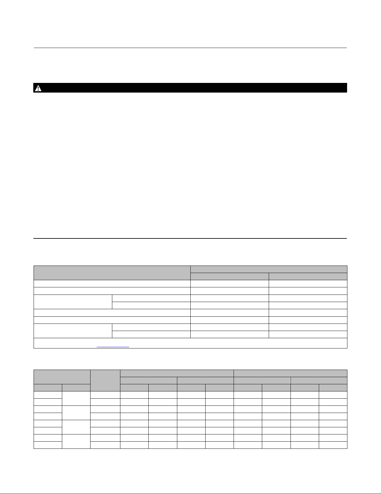
Figure 15. PTFE Packing Arrangement for Use in Fisher ENVIRO‐SEAL Bellows Seal Bonnets
UPPER WIPER
(KEY 12)
BUSHING
(KEY 13)
FEMALE ADAPTOR
PACKING RING
MALE ADAPTOR
SPACER (KEY 8)
SPACER (KEY 8)
A5855/IL
THRUST
RING
(KEY 39)
SPRING
(KEY 8)
THRUST
RING
9.5 mm
(KEY 39)
(3/8 INCH)
STEM
FOR S31603 (316 SST) PACKING
BOX PARTS
12.7 mm
(1/2 INCH)
STEM
9.5 mm
(3/8 INCH)
STEM
FOR ALL PACKING BOX MATERIALS
SINGLE ARRANGEMENTS
SPACER
(KEY 8)
12B4185−A−SHT2/IL12B4182−A−SHT2/IL12B4185−A−SHT1/IL12B4182−A/IL
12.7 mm
(1/2 INCH)
EXCEPT S31603
STEM
EW Valve
PACKING SET
(KEY 6)
July 2017
A5886-1
12B4183−A/IL
(3/8 INCH)
9.5 mm
STEM
BUSHING
(KEY 13)
THRUST
RING
(KEY 39)
BUSHING
(KEY 13)
SPACER
(KEY 8)
18A0906−D/IL
12.7 mm
(1/2 INCH)
STEM, NPS 2
VALVES
DOUBLE ARRANGEMENTS
18A5338−B/IL
12.7 mm
(1/2 INCH)
STEM, NPS 3 AND
NPS 4 VALVES
UPPER WIPER
(KEY 12)
BUSHING
(KEY 13)
FEMALE
ADAPTOR
PACKING RING
MALE ADAPTOR
SPACER (KEY 8)
PACKING SET
(KEY 6)
29
Page 30
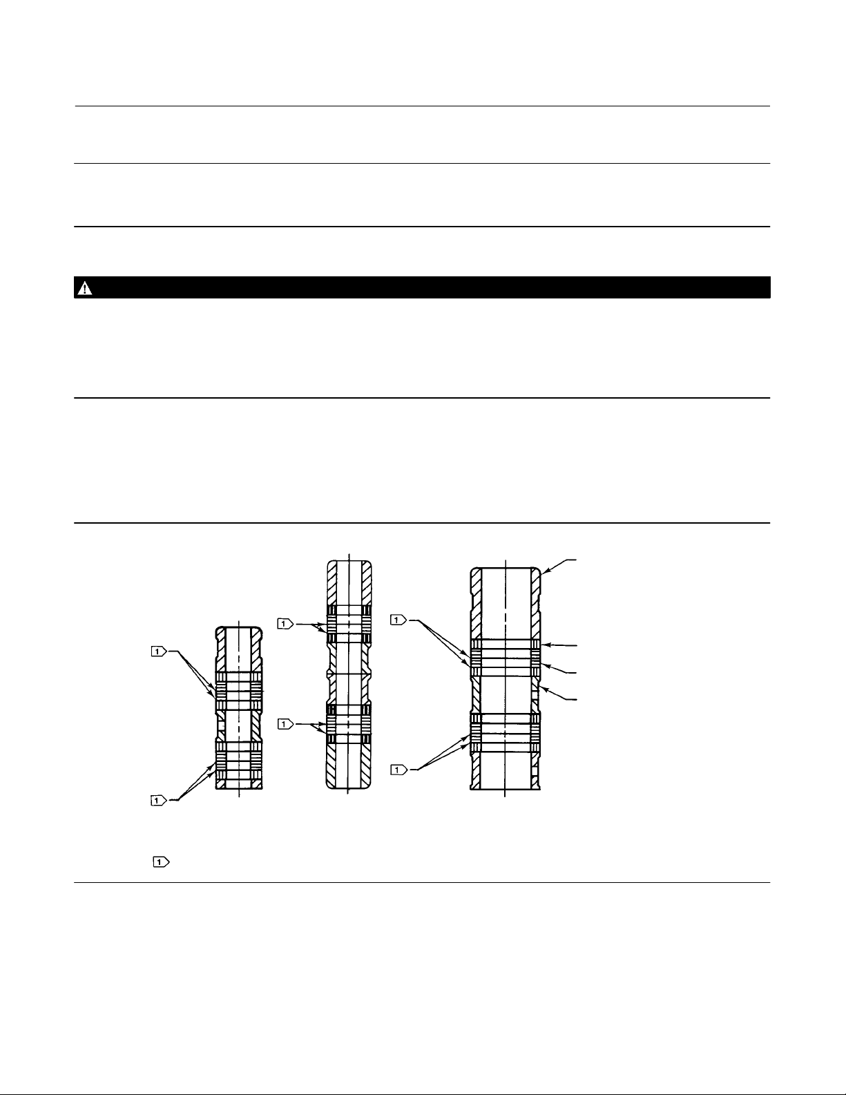
EW Valve
July 2017
Instruction Manual
D100399X012
Note
Stud(s) and nut(s) should be installed such that the manufacturer's trademark and material grade marking is visible, allowing easy
comparison to the materials selected and documented in the Emerson/Fisher serial card provided with this product.
WARNING
Personal injury or damage to equipment could occur if improper stud and nut materials or parts are used. Do not operate or
assemble this product with stud(s) and nut(s) that are not approved by Emerson/Fisher engineering and/or listed on the
serial card provided with this product. Use of unapproved materials and parts could lead to stresses exceeding the design
or code limits intended for this particular service. Install studs with the material grade and manufacturer's identification
mark visible. Contact your Emerson Automation Solutions representative immediately if a discrepancy between actual
parts and approved parts is suspected.
12. Properly lubricate the bonnet stud bolts. Install and tighten the bonnet hex nuts to the proper torque.
13. Install the new packing and the metal packing box parts according to the appropriate arrangement in figure 15 or
16.
14. Install the packing flange. Properly lubricate the packing flange stud bolts and the faces of the packing flange nuts.
Figure 16. Double Graphite Ribbon/Filament Arrangements for Use in Fisher ENVIRO‐SEAL Bellows Seal Bonnets
BUSHING
(KEY 13)
GRAPHITE FILAMENT
PACKING RING (KEY 7)
GRAPHITE RIBBON
PACKING RING (KEY 7)
SPACER (KEY 8)
12B6102−A/IL18A090−E/IL12B4181−A/IL
12.7 mm (1/2 INCH)
STEM, FOR NPS 3 AND
NPS 4 VALVES
A5887‐1
9.5 mm
(3/8 INCH)
STEM
NOTE:
0.102 mm (0.004 INCH) THICK SACRIFICIAL ZINC WASHERS; USE
ONLY ONE BELOW EACH GRAPHITE RIBBON RING.
12.7 mm
(1/2 INCH) STEM,
FOR NPS 2 VALVES
For graphite packing, tighten the packing flange nuts to the maximum recommended torque shown in table 8. Then,
loosen the packing flange nuts, and retighten them to the recommended minimum torque shown in table 8.
For other packing types, tighten the packing flange nuts alternately in small equal increments until one of the nuts
reaches the minimum recommended torque shown in table 8. Then, tighten the remaining flange nut until the
packing flange is level and at a 90‐degree angle to the valve stem.
30
Page 31

Instruction Manual
D100399X012
EW Valve
July 2017
15. Install the travel indicator parts and stem locknuts; mount the actuator on the valve body according to the
procedure in the appropriate actuator instruction manual.
Replacement of an Installed ENVIRO‐SEAL Bellows Seal Bonnet (Stem/Bellows Assembly)
1. Remove the actuator and bonnet according to steps 1 through 6 of the Replacing Packing procedure of the
Maintenance section.
2. Lift out the cage. Remove and discard the existing bonnet gasket and bellows gasket. Cover the valve body opening
to protect sealing surfaces and to prevent foreign material from entering the valve body cavity.
CAUTION
The ENVIRO‐SEAL stem/bellows assembly for easy-e valves is available only with a threaded and pinned plug/adaptor/stem
connection. The existing valve plug can be reused with the new stem/bellows assembly or a new plug can be installed. If
the existing valve plug is reused, and the adaptor is in good condition, it may be reused also. However, never reuse an old
adaptor with a new valve plug. Using an old adaptor with a new valve plug requires drilling a new pin hole in the adaptor.
This drilling weakens the adaptor and may cause failure in service. However, a used valve plug may be reused with a new
adaptor.
3. Inspect the existing valve plug and adaptor. If they are in good condition, they can be reused with the new
stem/bellows assembly and they do not need to be separated.
CAUTION
When removing/installing a valve plug on the ENVIRO‐SEAL stem/bellows assembly, the valve stem must not be rotated.
Damage to the bellows may result.
Do not grip the bellows shroud or other parts of the stem/bellows assembly. Grip only the flat areas on the stem where it
extends out of the top of the bellows shroud.
Note
The ENVIRO‐SEAL stem/bellows assembly has a one‐piece stem.
4. If the valve plug and adaptor are not in good condition and must be replaced, the valve plug/adaptor assembly
must first be removed from the stem/bellows assembly and then the valve plug removed from the adaptor. First,
place the stem/bellows assembly and valve plug in a soft‐jaw chuck or other type of vise so that the jaws grip a
portion of the valve plug that is not a seating surface. Drive out or drill out the pin (key 8). Drive out the pin (key 36,
figure 21).
5. Then, reverse the stem/bellows and plug/adaptor assembly in the soft‐jaw chuck or vise. Grip the flat areas on the
valve stem just below the threads for the actuator/stem connection. Unscrew the plug/adaptor assembly from the
stem/bellows assembly. Unscrew the valve plug from the adaptor.
6. To attach either the existing or a new valve plug to the stem of the new ENVIRO‐SEAL stem/bellows assembly, first
attach the plug to the adaptor (if the valve plug was removed from the adaptor) as follows:
D Locate the adaptor. Notice that a hole has not been drilled in the new adaptor threads where the plug screws onto
the adaptor.
D Secure the valve plug in a soft‐jaw chuck or other type of vise. Do not grip the plug on any seating surface. Position
the plug in the chuck or vise for easy threading of the adaptor.
31
Page 32

EW Valve
July 2017
D Thread the adaptor into the valve plug and tighten to the appropriate torque value.
7. Complete the installation by following steps 7 through 15 of the ENVIRO‐SEAL Bellows Seal Bonnet installation
instructions given above.
Instruction Manual
D100399X012
Purging the ENVIRO‐SEAL Bellows Seal Bonnet
The ENVIRO‐SEAL bellows seal bonnet has been designed so that it can be purged or leak tested. Refer to figure 21 for
an illustration of an ENVIRO‐SEAL bellows seal bonnet. Perform the following steps for purging or leak testing.
1. Remove the two diametrically opposed pipe plugs (key 16, figure 21).
2. Connect a purging fluid to one of the pipe plug connections.
3. Install appropriate piping or tubing in the other pipe plug connection to pipe away the purging fluid or to make a
connection to an analyzer for leak testing.
4. When purging or leak testing has been completed, remove the piping or tubing and reinstall the pipe plugs (key 16,
figure 21).
Parts Ordering
Each body‐bonnet assembly is assigned a serial number, which can be found on the valve. This same number also
appears on the actuator nameplate when the valve is shipped from the factory as part of a control valve assembly.
Refer to the serial number when contacting your Emerson sales office
assistance. When ordering replacement parts, refer to the serial number and to the 11‐character part number for each
part required from the following parts list.
WARNING
Use only genuine Fisher replacement parts. Components that are not supplied by Emerson Automation Solutions should
not, under any circumstances, be used in any Fisher valve, because they may void your warranty, might adversely affect the
performance of the valve, and could cause personal injury and property damage.
or Local Business Partner for technical
32
Page 33

Instruction Manual
D100399X012
Parts Kits
Gasket Kits
Gasket Kits (includes keys 10, 12, 13, and 53; plus 11 and 14 for restricted trim)
Standard Trim Cage
Whisper Trim I Cage
VALVE SIZE, NPS
4x2 RGASKETX182 RGASKETX442
6x4x2‐1/2 RGASKETX282 - - -
6x4 or 8x4 RGASKETX212 RGASKETX472
8x6 or 12x6
CL300, CL600, or CL900
8x6 or 12x6
Whisper Trim I
10x8 or 12x8 RGASKETX232 10A3265X152
1. Includes a quantity 2 of key 10.
Cavitrol III - 1 Stage Cage
-198 to 593_C (-325 to 1100_F) -198 to 593_C (-325 to 1100_F)
Part Number Part Number
RGASKETX392 - - -
RGASKETX412
(1)
EW Valve
July 2017
Cavitrol III - 2 Stage Cage
Whisper Trim III Cage
WhisperFlo Cage
- - -
Packing Kits
Standard Packing Repair Kits
Packing repair kits for standard packing include keys 6, 8, 10, 11 and 12.
Note
Kits do not apply to alloy C (N10276 and CW2M), Alloy 20 (N08020 and CN7M), or alloy 400 (N04400 and M35‐1) trims.
Standard Packing Repair Kits (Non Live‐Loaded)
Stem Diameter, mm (Inches)
Yoke Boss Diameter, mm (Inches)
PTFE (Contains keys 6, 8, 10, 11, and 12) RPACKX00022 RPACKX00032 RPACKX00342 RPACKX00352
Double PTFE (Contains keys 6, 8, 11, and 12) RPACKX00052 RPACKX00062 RPACKX00362 RPACKX00372
PTFE/Composition (Contains keys 7, 8, 11, and 12) RPACKX00082 RPACKX00092 - - - - - -
Single Graphite Ribbon/Filament (Contains keys 7 [ribbon ring],
7 [filament ring], 8, and 11)
Single Graphite Ribbon/Filament (Contains keys 7 [ribbon ring],
7 [filament ring], and 11)
Single Graphite Ribbon/Filament (Contains keys 7 [ribbon ring],
7 [filament ring])
Double Graphite Ribbon/Filament (Contains keys 7 [ribbon ring],
7 [filament ring], 8, and 11)
12.7 (1/2)
71 (2‐13/16)
RPACKX00112 RPACKX00122 - - - - - -
- - - - - - RPACKX00532 RPACKX00542
RPACKX00142 RPACKX00152 - - - - - -
RPACKX00172 RPACKX00182 - - - - - -
19.1 (3/4)
90 (3‐9/16)
25.4 (1)
127 (5)
31.8 (1-1/4)
127 (5, 5H)
33
Page 34

EW Valve
July 2017
Instruction Manual
D100399X012
HIGH‐SEAL and ENVIRO‐SEAL Packing Retrofit Kits
Retrofit kits include parts to convert valves with existing standard bonnets to the HIGH‐SEAL or ENVIRO‐SEAL packing
box construction. Refer to figure 17 for key numbers for HIGH‐SEAL packing. For ENVIRO‐SEAL packing, refer to figure
18 for PTFE packing key numbers, figure 19 for Graphite ULF packing key numbers, and figure 20 for duplex packing
key numbers.
Stems and packing box constructions that do not meet Emerson stem finish specifications, dimensional tolerances,
and design specifications, may adversely alter the performance of this packing kit.
HIGH‐SEAL Packing Retrofit Kits
Stem Diameter, mm (Inches)
Yoke Boss Diameter, mm (Inches)
4200 psi Process Pressure Rating (Contains keys 200
through 212)
ENVIRO‐SEAL Packing Retrofit Kits
Stem Diameter, mm (Inches)
Yoke Boss Diameter, mm (Inches)
Double PTFE (Contains keys 200, 201, 211, 212, 214,
215, 217, 218, tag, cable tie)
Graphite ULF (Contains keys 200, 201, 207, 208, 209,
210, 211, 212, 214, 217, tag, cable tie)
Duplex (Contains keys 200, 201, 207, 209, 211, 212,
214, 215, 216, 217, tag, cable tie)
12.7 (1/2)
71 (2‐13/16)
11B2182X052 11B2184X052 11B2187X052 11B2189X052
12.7 (1/2)
71 (2‐13/16)
RPACKXRT022 RPACKXRT032 RPACKXRT042 RPACKXRT052
RPACKXRT272 RPACKXRT282 RPACKXRT292 RPACKXRT302
RPACKXRT222 RPACKXRT232 RPACKXRT242 RPACKXRT252
19.1 (3/4)
90 (3‐9/16)
19.1 (3/4)
90 (3‐9/16)
25.4 (1)
127 (5)
25.4 (1)
127 (5)
31.8 (1‐1/4)
127 (5, 5H)
31.8 (1‐1/4)
127 (5, 5H)
ENVIRO‐SEAL Packing Repair Kits
Repair kits include parts to replace the ”soft” packing materials in valves that already have ENVIRO‐SEAL packing
arrangements installed or in valves that have been upgraded with ENVIRO‐SEAL retrofit kits. Refer to figure 18 for key
numbers for PTFE packing, figure 19 for key numbers for Graphite ULF packing, and figure 20 for key numbers for
duplex packing.
Stems and packing box constructions that do not meet Emerson stem finish specifications, dimensional tolerances,
and design specifications, may adversely alter the performance of this packing kit.
ENVIRO‐SEAL Packing Repair Kits
Stem Diameter, mm (Inches)
Yoke Boss Diameter, mm (Inches)
Double PTFE (Contains keys 214, 215, 218) RPACKX00202 RPACKX00212 RPACKX00222 RPACKX00232
Graphite ULF (Contains keys 207, 208, 209, 210, 214) RPACKX00602 RPACKX00612 RPACKX00622 RPACKX00632
Duplex (Contains keys 207, 209, 214, 215) RPACKX00302 RPACKX00312 RPACKX00322 RPACKX00332
12.7 (1/2)
71 (2‐13/16)
19.1 (3/4)
90 (3‐9/16)
25.4 (1)
127 (5)
31.8 (1‐1/4)
127 (5, 5H)
34
Page 35

Instruction Manual
D100399X012
EW Valve
July 2017
Figure 17. Typical Fisher HIGH‐SEAL Packing System
STUD
(KEY 200)
HEX NUT
(KEY 212)
PACKING
FLANGE
(KEY 201)
SPRING
(KEY 202)
PACKING RING
(KEY 209)
GRAPHITE RIBBON
PACKING RING
(KEY 210)
PACKING
BOX RING
(KEY 211)
A6138
SCREW
(KEY 204)
LOAD
SCALE
(KEY 205)
INDICATOR
DISK
(KEY 206)
PACKING
FOLLOWER
(KEY 203)
GUIDE
BUSHING
(KEY 207)
GUIDE
BUSHING
(KEY 208)
Figure 18. Typical Fisher ENVIRO‐SEAL Packing
System with PTFE Packing
Figure 19. Typical Fisher ENVIRO‐SEAL Packing
System with Graphite ULF Packing
39B4612/A
Figure 20. Typical Fisher ENVIRO‐SEAL Packing
System with Duplex Packing
A6297‐1
200
212
201
215
216
207
209
211
A6722
213
217
207
207
214
207
35
Page 36

EW Valve
July 2017
Parts List
Numerous available combinations of valve parts make
selection of some parts difficult; when ordering valve
parts for which a part number is not listed, provide the
valve serial number with the order, permitting proper
selection of replacement parts to be made at the
factory.
Note
Part numbers are shown for recommended spares only. For part
numbers not shown, contact your Emerson sales office
Partner.
Bonnet (figures 4, 5, 6, and 21)
Key Description Part Number
1 Bonnet
If you need a bonnet and/or and ENVIRO‐SEAL bellows seal
bonnet as a replacement part, order by valve size and stem
diameter, serial number, and desired material.
2 Extension Bonnet Bushing
3 Packing Flange
3 ENVIRO‐SEAL bellows seal packing flange
4 Packing Flange Studs
4 ENVIRO‐SEAL bellows seal stud bolt (2 req'd)
5 Packing Flange Nuts
5 ENVIRO‐SEAL bellows seal packing flange
nut (2 req'd)
6* Single PTFE V‐Ring Packing Set See following table
6* ENVIRO‐SEAL bellows seal packing set
PTFE (1 req'd for single, 2 req'd for
double)
Size 4x2 w/ 12.7 mm (1/2 inch) stem 12A9016X012
Sizes 6x4x2‐1/2, 6x4, & 8x4
w/ 12.7 mm (1/2 inch) stem
(For double PTFE only)(2 req'd) 12A8832X012
7* Individual Packing Ring See following table
7* ENVIRO‐SEAL bellows seal packing ring
Double packing graphite filament
(4 req'd)
Size 4x2 w/ 12.7 mm (1/2 inch) stem 1P3905X0172
Sizes 6x4x2‐1/2, 6x4, & 8x4
w/ 12.7 mm (1/2 inch) stem 14A0915X042
7* ENVIRO‐SEAL bellows seal packing ring
Double packing graphite ribbon
(4 req'd)
Size 4x2 w/ 12.7 mm (1/2 inch) stem 18A0908X012
Sizes 6x4x2‐1/2, 6x4, & 8x4
w/ 12.7 mm (1/2 inch) stem 18A0918X012
8 Packing Box Spring or Lantern Ring
8 ENVIRO‐SEAL bellows seal spring, 316 SST
Size 4x2 w/ 12.7 mm
(1/2 inch) stem (single packing only)
8 ENVIRO‐SEAL bellows seal spacer, S31600
For single PTFE packing
Size 4x2 w/ 12.7 mm (1/2 inch) stem
or Local Business
Instruction Manual
D100399X012
Key Description Part Number
For double PTFE, graphite rib/fil packing
Size 4x2 w/ 12.7 mm (1/2 inch) stem (2 req'd)
Size 6x4x2‐1/2, 6x4, & 8x4
w 12.7 mm (1/2 inch) stem (2 req'd)
8 ENVIRO‐SEAL bellows seal spacer, N10276
For single PTFE packing)
Size 4x2 w/ 12.7 mm (1/2 inch) stem
(1 req'd)
For double PTFE, graphite rib/fil packing
Size 4x2 w/ 12.7 mm (1/2 inch) stem (2 req'd)
Size 6x4x2‐1/2, 6x4, & 8x4
w 12.7 mm (1/2 inch) stem (2 req'd)
9* Individual Packing Ring See following table
10 Special Washer See following table
11* Packing Box Ring, S31600
12.7 mm (1/2 inch) stem 1J873235072
19.1 mm (3/4 inch) stem 1J873335072
25.4 mm (1 inch) stem 1J873435072
31.8 mm (1‐1/4 inch) stem 1J873535072
12* Upper Wiper, felt
12.7 mm (1/2 inch) stem 1J872706332
19.1 mm (3/4 inch) stem 1J872806332
25.4 mm (1 inch) stem 1J872906332
31.8 mm (1‐1/4 inch) stem 1J873006332
12* ENVIRO‐SEAL bellows seal upper wiper, felt
Size 4x2 w/ 12.7 mm (1/2 inch) stem 18A0868X012
Sizes 6x4x2‐1/2, 6x4, & 8x4
w/ 12.7 mm (1/2 inch) stem 18A0870X012
13 Packing follower, 316 stainless steel
13* ENVIRO‐SEAL bellows seal bushing
size 4x2 w/ 12.7 mm (1/2 inch) stem
(2 req'd)
S31600 (316 SST) 18A0820X012
R30006 (alloy 6) 18A0819X012
S31600 chrome coated 11B1155X012
For size 6x4x2‐1/2, 6x4, & 8x4
w/ 12.7 mm (1/2 inch) stem (1 req'd)
S31600 (316 SST) 18A0824X012
R30006 (alloy 6) 18A0823X012
S31600 chrome coated 11B1157X012
13* ENVIRO‐SEAL bellows seal bushing/liner
size 4x2 w/ 12.7 mm (1/2 inch) stem
(2 req'd)
N10276 bushing, PTFE/glass liner 12B2713X012
N10276 bushing, PTFE/carbon liner 12B2713X042
For size 6x4x2‐1/2, 6x4, & 8x4
w/ 12.7 mm (1/2 inch) stem (1 req'd)
N10276 bushing, PTFE/glass liner 12B2715X012
N10276 bushing, PTFE/carbon liner 12B2715X042
14 Packing Box Pipe Plug
14 Lubricator, steel/440 SST
14 Lubricator/Isolating Valve Assy. pl steel
15 Yoke Locknut, steel
15 ENVIRO‐SEAL bellows seal yoke locknut, steel
16 Pipe Plug for double‐tapped bonnet
For size 4x2 thru 12x6 valve
Steel for WCC steel bonnet
S31600 for chrome moly steel or
316 SST bonnet
For size 10x8 or 12x8 valve
Steel for WCC steel bonnet
36
*Recommended spare parts
Page 37

Instruction Manual
D100399X012
EW Valve
July 2017
Key Description Part Number
S31600 for chrome moly steel or
316 SST bonnet
16 ENVIRO‐SEAL bellows seal pipe plug
(2 req'd)
20* ENVIRO‐SEAL bellows seal stem/bellows
assembly
1 ply bellows
S31603 (316L SST) trim, N06625
bellows
Size 4x2 w/ 12.7 mm (1/2 inch) stem 32B4226X012
Size 6x4x2‐1/2, 6x4, & 8x4
w/ 12.7 mm (1/2 inch) stem 32B4228X012
N06022 trim, N06022
bellows
Size 4x2 w/ 12.7 mm (1/2 inch) stem 32B4226X022
Size 6x4x2‐1/2, 6x4, & 8x4
w/ 12.7 mm (1/2 inch) stem 32B4228X022
20* ENVIRO‐SEAL bellows seal stem/bellows
assembly (cont'd)
2 ply bellows
S31603 (316L SST) trim, N06625
bellows
Size 4x2 w/ 12.7 mm (1/2 inch) stem 32B4226X032
Size 6x4x2‐1/2, 6x4, & 8x4
w/ 12.7 mm (1/2 inch) stem 32B4228X032
Keys 6*, 7*, 8, and 10 Packing Box Parts
DESCRIPTION KEY NO.
Packing Set, PTFE (1 req'd for single, 2
req”d for double)
Spring, Stainless Steel
(for single only)
PTFE V‐Ring Packing
PTFE/composition
Packing
Graphite
Ribbon/Filament
1. Key 6 for double construction contains one extra Lower Wiper for all sizes. Discard upon assembly.
Lantern Ring, Stainless Steel
(for double only)
Quantity required Double ‐ ‐ ‐ 2 1 1 1
Special washer, Stainless Steel (for
single only)
Packing Ring, PTFE composition 7 1E319001042 1E319101042 1D7518X0012 1D7520X0012
Quantity required Double ‐ ‐ ‐ 10 8 8 8
Lantern Ring, Stainless Steel (1 req'd) 8 1J9623 35072 0N028435072 0U099735072 0W087135072
Graphite Ribbon Ring 7 1V3802X0022 1V2396X0022 1U6768X0022 1V5666X0022
Quantity required
Graphite Filament Ring 7 1E3190X0222 1E3191X0282 1D7518X0132 1D7520X0162
Quantity required
Lantern Ring 8 1J962335072 0N028435072 0U099735072 0W087135072
Quantity required
(1)
Single ‐ ‐ ‐ 2 2 2 2
Double ‐ ‐ ‐ 3 3 3 3
Single ‐ ‐ ‐ 2 3 3 3
Double ‐ ‐ ‐ 4 5 5 5
Single ‐ ‐ ‐ 3 2 2 2
Double ‐ ‐ ‐ 2 1 1 1
6 1R290201012 1R290401012 1R290601012 1R290801012
8 1F125537012 1F125637012 1D582937012 1D387437012
8 1J269335072 0N028435072 0U099735072 0W087135072
10 1F125136042 1F125036042 1H982236042 1H995936042
Key Description Part Number
N06022 trim, N06022
bellows
Size 4x2 w/ 12.7 mm (1/2 inch) stem 32B4226X042
Size 6x4x2‐1/2, 6x4, & 8x4
w/ 12.7 mm (1/2 inch) stem 32B4228X042
22* ENVIRO‐SEAL bellows seal bonnet gasket,
graphite/laminate
Size 4x2 valve 12B6318X022
Size 6x4x2‐1/2, 6x4, & 8x4 valve 12B6320X022
24 ENVIRO‐SEAL bellows seal adaptor
25 Cap Screw for 127 mm (5 inch) yoke boss,
steel (8 req'd)
Size 12x8 valve, CL900
26 Hex Nut for 127 mm (5 inch) yoke boss,
pl steel (8 req'd)
27 Pipe Nipple for lubricator/isolating valve
28 Warning Nameplate for ENVIRO‐SEAL bellows
29 Drive Screw for ENVIRO‐SEAL bellows, stain‐
less steel (2 req'd)
36* ENVIRO‐SEAL bellows seal pin, N06022 12B3951X012
37 Warning Tag for ENVIRO‐SEAL bellows
38 Tie for ENVIRO‐SEAL bellows
39 ENVIRO‐SEAL bellows seal thrust ring
Trim S31600
Single PTFE Packing
Size 4x2 w/ 12.7 mm (1/2 inch) stem
(2 req'd)
STEM DIAMETER, mm (INCHES)
12.7 (1/2) 19.1 (3/4) 25.4 (1) 31.8 (1‐1/4)
*Recommended spare parts
37
Page 38

EW Valve
July 2017
Figure 21. Typical Fisher Bonnet with Single PTFE V‐Ring Packing Set
E0201
PLAIN BONNET
Instruction Manual
D100399X012
30A9425-A
DETAIL OF 5‐INCH (127 mm) YOKE
BOSS ACTUATOR BOLTING
42B3947-A
APPLY LUB
ENVIRO-SEAL
BELLOWS SEAL BONNET
35A3976-A
DETAIL OF NPS 12x8 CL900
YOKE BOSS BOLTING
CU3911-C
STYLE 1 OR 2
EXTENSION BONNET
38
Page 39

Instruction Manual
D100399X012
EW Valve
July 2017
Valve Body
(figures 22 through 24)
Note
This parts list provides part numbers for standard valves and valves with
Whisper Trim I cages only. For part numbers for valves with WhisperFlo,
Whisper Trim III, or Cavitrol III cages, contact your Emerson sales office
or Local Business Partner.
Key Description Part Number
1 Valve Body
If you need a valve body as a replacement part, order
by valve size, serial number, and desired material.
2* Valve Plug See following table
3* Cage See following table
4 Cage Adaptor for restricted‐capacity
Size 6x4x2‐1/2 valve
5 Seat Ring Adaptor for restricted‐capacity
Size 6x4x2‐1/2 valve
6* EWD Piston Ring
Class II shutoff minimum (1 req'd)
To 900_F (to 482_C), graphite
Size 4x2 valve 1U2258X0012
Size 6x4x2‐1/2 valve 1U2300X0012
Size 6x4 or 8x4 valve 1U2392X0012
Size 8x6 or 12x6 valve
For all except Whisper Trim III cages 1U5069X0012
Size 10x8 or 12x8 valve 10A3262X022
Optional Class IV shutoff, graphite
Size 6x4 or 8x4 valve (3 req'd)
Standard, to 482_C (to 900_F) 17A3988X012
High‐temp, 482 to 593_C (901 to 1100_F) 17A3988X022
Size 8x6 or 12x6 valve (3 req'd)
For all except Whisper Trim III cages
Standard, 482_C (to 900_F) 17A3990X012
High‐temp, 482 to 593_C
(901 to 1100_F) 17A3990X022
Size 10x8 or 12x8 valve (2 req'd)
Standard, to 482_C (to 900_F) 17A3991X012
High‐temp, 482 to 593_C (901 to 1100_F) 17A3991X022
Key Description Part Number
7* Valve Plug Stem See following table
8* Pin, S31600 (316 SST)
EWD or EWT
12.7 mm (1/2 inch) stem dia 1V322735072
19.1 mm (3/4 inch) stem dia 1V326035072
25.4 mm (1 inch) or 31.8 mm (1‐1/4 inch)
stem dia 1V334035072
EWS
12.7 mm (1/2 inch) stem dia 1B599635072
19.1 mm (3/4 inch) stem dia 1F723635072
25.4 mm (1 inch) or 31.8 mm (1‐1/4 inch)
stem dia 1D269735072
Size 10x8 or 12x8 valve,
31.8 mm (1‐1/4 inch) stem dia 1K249838992
9* Seat Ring See following table
10* thru 14* Gaskets See following table
15 Stud Bolt, steel
Plain, ext style 1, or ext style 2 bonnet
All constructions except 2‐stage Cavitrol III
Size 4x2 valve (8 req'd)
Size 6x4, 6x4x2‐1/2,
or 8x4 valve (8 req'd)
Size 8x6 CL300 or CL600 valve (12 req'd)
Whisper Trim I cage (4‐inch travel)
All other constructions except Whisper I (4‐inch travel),
Whisper III, and 2‐stage Cavitrol III
Size 8x6 CL900 valve (12 req'd)
Size 12x6 valve (12 req'd)
Whisper Trim I cage (4‐inch travel)
All other constructions except Whisper I (4‐inch travel),
Whisper III, and 2‐stage Cavitrol III
Size 10x8 valve (16 req'd)
Size 12x8
CL300 or CL600 valve (16 req'd)
Size 12x8 CL900 valve (12 req'd)
16 Stud Bolt Nut, steel, factory lubricated
Size 4x2 valve (8 req'd)
Size 6x4, 6x4x2‐1/2,
or 8x4 valve (8 req'd)
Size 8x6 CL300 or CL600 valve (12 req'd)
Size 8x6 CL900 valve (12 req'd)
Size 12x6 valve (12 req'd)
Size 10x8 valve (16 req'd)
Size 12x8 valve, CL300 or CL600 (16 req'd)
Size 12x8 CL900 (12 req'd)
*Recommended spare parts
39
Page 40

EW Valve
July 2017
Figure 22. Fisher EWD Valve through NPS 12x6 with Optional Drain Plug
Instruction Manual
D100399X012
57A3966‐A
DETAIL OF MULTIPLE
PISTON RING FOR
CLASS IV SHUTOFF
FLOW DIRECTION
WHISPER TRIM
RESTRICTED TRIM DETAIL
30A9547‐G
STD TRIM
CAVITROL TRIM
40
41A9275-B
VALVE ASSEMBLY WITH
STANDARD CAGE
Page 41

Instruction Manual
D100399X012
EW Valve
July 2017
Key Description Part Number
17 Pipe Plug for drain‐tapped valve
18 Flow Arrow, SST
19 Drive screw, SST (6 req'd)
21* Disk Retainer for PTFE‐seat EWS or EWT
Size 4x2 valve, S31600 1V710835072
Size 6x4x2‐1/2 valve, S31600 1V710935072
Size 6x4 or 8x4 valve, CF8M 1V711533092
Size 8x6 or 12x6 valve, CF8M
For all except Whisper Trim III cages 1V711833092
Size 10x8 or 12x8 valve
CF8M 10A4466X012
R30006 (Alloy 6) 10A4466X022
22* Disk Seat for PTFE‐seat EWS or EWT
Size 4x2 valve
S31600 10A5936X012
S41600 (416 SST) HT 10A5936X072
Size 6x4x2‐1/2 valve, S31600 1V711135072
Size 6x4 valve, CF8M 1V712533092
Size 8x4 valve, S31600 1V712633092
Size 8x6 or 12x6 CL300 or CL600 valve, 316 SST
For all except Whisper Trim III cages
Size 8x6 valve only
51 mm (2 inch) or 76 mm (3 inch) travel 2V721733092
102 mm (4 inch) travel 20A1180X012
Size 12x6 valve only
51 mm (2 inch) or 76 mm (3 inch) travel 2V712733092
102 mm (4 inch) travel 20A1180X012
Size 8x6 CL900 valve, CF8M 21A9344X012
Size 10x8 or 12x8 valve
CF8M 20A4467X012
R30006 20A4467X022
23* Disk for PTFE‐seat EWS or EWT, PTFE
Size 4x2 valve 1V710706242
Size 6x4x2‐1/2 valve 1V711006242
Size 6x4 or 8x4 valve 1V711606242
Size 8x6 or 12x6 valve
For all except Whisper Trim III cages 1V711906242
Size 10x8 or 12x8 valve 20A4468X012
26 Load Ring for Size 10x8 or 12x8 valve only
27* Retaining Ring for spring‐loaded EWT seal rings,
302 SST
All except 2‐stage Cavitrol III construction
Size 4x2 valve 10A4210X012
Size 6x4 or 8x4 valve 10A4225X012
Size 6x4x2‐1/2 valve,
std construction only 10A4219X012
28* EWT 2‐Piece Seal Ring for all except
Cavitrol III constructions
Carbon‐filled PTFE (not used w/ size NPS 12x8 valve)
Size 4x2 valve 1V550805092
Size 6x4x2‐1/2 valve 1V659505092
Size 6x4 or 8x4 valve 1V659905092
Size 8x6 or 12x6 valve
For std, Whisper Trim I cages 1V660105092
Key Description Part Number
Spring‐loaded
Size 4x2 valve 10A4206X012
Size 6x4x2‐1/2 valve 10A4215X012
Size 6x4 or 8x4 valve 10A4223X012
Size 8x6 or 12x6 valve
For std and Whisper Trim I cages 10A2643X022
Size 10x8 or 12x8 valve 10A3261X012
29* Backup Ring for EWT 2‐piece seal ring
w/o spring loading
Fluorocarbon
Size 4x2 valve 1V550705292
Size 6x4x2‐1/2 valve 1V659405292
Size 6x4 or 8x4 valve 1V659805292
Size 8x6 or 12x6 valve
For std. Whisper Trim I cages 1V660005292
Ethylene‐Propylene
Size 4x2 valve 1V5507X0042
Size 6x4x2‐1/2 valve 1V6594X0032
Size 6x4 or 8x4 valve 1V6598X0022
Size 8x6 or 12x6 valve
For std, Whisper Trim I cages 1V6600X0022
29* Backup Ring for spring‐loaded EWT seal rings
For all except 2‐stage Cavitrol III constructions
Size 4x2 valve, S41600 10A4208X012
Size 6x4x2‐1/2 valve, S41600 10A4217X012
Size 6x4 or 8x4 valve, S41600 10A4224X012
For Whisper III constructions only
Size 8x6 or 12x6 valve
S41600 12A3332X012
S31600 12A3332X022
31* Cage Retainer, required for Whisper Trim III and Cavitrol III cages
only. See your Emerson Automation Solutions sales office.
32 Bonnet Spacer
51 Anti‐seize lubricant (not furnished)
52 Cage Spacer
53* Shim See following table
55 Wire
(1)
PTFE for all except 2‐stage Cavitrol III
(2)
C‐seal Trim (figure 9)
2* Plug/Retainer see following table
3* Cage see following table
7* Valve Plug Stem, S20910 see following table
9* Seat Ring see following table
64* C‐seal, N07718 see following table
TSO Trim (figures 7 and 8)
3* Cage See following table
9* Seat Ring See following table
2* Plug/Stem Assembly See following table
28* Seal Ring See following table
63* Anti‐Extrusion Ring See following table
29* Back Up Ring See following table
27* Retaining Ring See following table
*Recommended spare parts
1. Spring is N06022.
2. Not for steam or water above 82_C (180_F).
41
Page 42
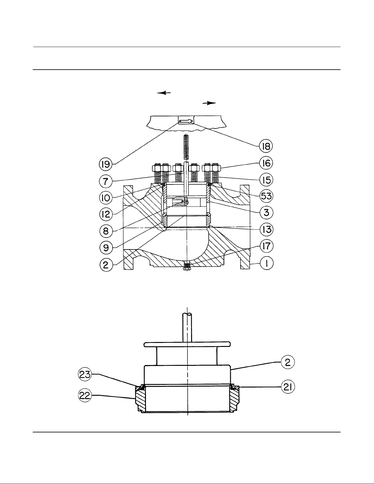
EW Valve
July 2017
Figure 23. Fisher EWS Valve through NPS 12x6
Instruction Manual
D100399X012
FLOW DIRECTION
CAVITROL TRIM
STD TRIM
WHISPER TRIM
42
COMPLETE VALVE ASSEMBLY WITH METAL SEAT WITH OPTIONAL DRAIN PLUG
31A9274‐C
ELASTOMERIC SEAT DETAIL
Page 43
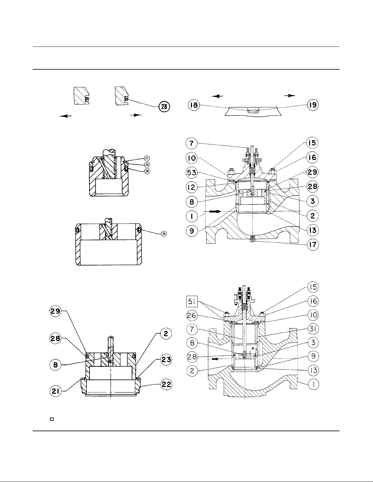
Instruction Manual
D100399X012
Figure 24. Typical Fisher EWT Valve Assemblies
EW Valve
July 2017
FLOW DIRECTION
43A8590‐B
A2069‐2
VIEW A
FLOW UP
VIEW A
FLOW DOWN
CORRECT SPRING‐LOADED SEAL
RING ORIENTATION
47.6 TO 136.5 mm (1.875 TO 5.375 INCH)
178 mm (7 INCH) AND 203 mm (8 INCH)
PORT DIAMETERS
PORT DIAMETER
DETAILS OF VALVE PLUG WITH
SPRING‐LOADED SEAL RING
WHISPER TRIM STD TRIM
CAVITROL TRIM
43A8590‐B
43A8592‐B
NPS 4x2 THROUGH 12x6 VALVE
WITH STANDARD CAGE AND METAL SEAT
WITH OPTIONAL DRAIN PLUG
43A8590‐B
DETAIL OF PTFE SEAT AND VALVE PLUG
WITH 2‐PIECE SEAL RING
APPLY LUB
55A8288‐B
NPS 12x8 VALVE
WITH STANDARD CAGE
43
Page 44

EW Valve
July 2017
Figure 25. FGM Gasket Detail with Optional Drain Plug
Instruction Manual
D100399X012
A2713*
RESTRICTED‐TRIM DETAIL
FULL‐CAPACITY TRIM DETAIL
FGM GASKETS ALSO MUST BE
INSTALLED WHERE REQUIRED
IN SEAT RING AREA PER
FIGURE 22, 23, OR 24
44
Page 45

Instruction Manual
D100399X012
Figure 26. NPS 4x2 Through 12x8 Fisher Valves with 1‐Stage Cavitrol III Cage
FLOW DIRECTION
EW Valve
July 2017
58A1012‐B
VIEW A
NPS 4x2 THROUGH 8x4
54A8146‐B
NPS 8x6 THROUGH 12x6
VALVES
58A1012‐B
NPS 4x2 THROUGH 12x6 VALVES
WITH OPTIONAL DRAIN PLUG
NOTES:
NOT REQUIRED ON NPS 8x6 AND 12x6 VALVES.
1
KEYS 2, 7, & 8 ARE SUPPLIED AS AN ASSEMBLY (KEY 2)
2
FOR NPS 8x6 AND 12x6 VALVES.
3
NOT REQUIRED FOR NPS 12x8 VALVES WITH 4‐ OR
6‐INCH TRAVEL.
VIEW A
VALVES
VIEW A
APPLY LUB
58A1015‐A
NPS 12x8 VALVE
FLOW DIRECTION
54A8142‐A
VIEW A
NPS 8x6 CL900
VALVE GASKETING DETAIL
WITH OPTIONAL DRAIN PLUG
45
Page 46

EW Valve
July 2017
Figure 27. NPS 4x2 Through 12x8 Fisher Valves with 2‐Stage Cavitrol III Cage
FLOW DIRECTION
VIEW A
Instruction Manual
D100399X012
VIEW A
54A7497‐B
APPLY LUB
NPS 4x2 THROUGH 12x6 VALVES
WITH OPTIONAL DRAIN PLUG
54A7495‐A
55A8886‐A
NPS 12x8 VALVE
NPS 8x6 CL900
VALVE GASKETING DETAIL
WITH OPTIONAL DRAIN PLUG
46
Page 47

Instruction Manual
D100399X012
Figure 28. Typical Fisher EWD Valve with Whisper Trim III Cage
FLOW DIRECTION
30A9547‐G
EW Valve
July 2017
52A3328‐C
COMPLETE VALVE ASSEMBLY WITH WHISPER TRIM III CAGE,
SINGLE GRAPHITE PISTON RING, AND OPTIONAL DRAIN PLUG
47
Page 48

EW Valve
July 2017
Figure 29. Typical Fisher WhisperFlo Trims
SEAT RING
BONNET SPACER
CAGE RETAINER
WhisperFlo CAGE
DISK RETAINER
DISK
DISK SEAT
Instruction Manual
D100399X012
EWD CLASS IV
(METAL SEAT)
SEAT RING
EWD/EWT
(METAL SEAT)
SPRING‐LOADED SEAL RING
EWT WITH
(SOFT SEAT)
BONNET SPACER
CAGE RETAINER
WhisperFlo CAGE
DISK RETAINER
DISK
DISK SEAT
EWT
(SOFT SEAT)
48
Page 49

Instruction Manual
D100399X012
Key 2* Fisher EWD Valve Plug
VALVE SIZE, NPS MATERIAL
12.7 (1/2) 19.1 (3/4) 25.4 (1) 31.8 (1‐1/4)
Hardened S41600 (416 SST) 1V657546172 1V657646172 ‐ ‐ ‐ ‐ ‐ ‐
4 x 2
(for 1 piston ring only)
S31600 (316 SST) 1V657535072 1V657635072 ‐ ‐ ‐ ‐ ‐ ‐
S31600/CoCr‐A on seat and guide
S31600/CoCr‐A on seat and guide
(1)
11A5326X012 11A5327X012 ‐ ‐ ‐ ‐ ‐ ‐
(2)
11A5328X012 11A5329X012 ‐ ‐ ‐ ‐ ‐ ‐
Hardened S41600 1V657746172 1V657846172 ‐ ‐ ‐ ‐ ‐ ‐
6 x 4 x 2‐1/2
(for 1 piston ring only)
S31600 1V657735072 1V657835072 ‐ ‐ ‐ ‐ ‐ ‐
S31600/CoCr‐A on seat and guide
S31600/CoCr‐A on seat and guide
(1)
11A5332X012 11A5333X012 ‐ ‐ ‐ ‐ ‐ ‐
(2)
11A5334X012 11A5335X012 ‐ ‐ ‐ ‐ ‐ ‐
Hardened S41600 1V658146172 1V658246172 1V658346172 ‐ ‐ ‐
For 1 piston ring
6 x 4 or 8 x 4
For 3 piston rings
S31600 1V658135072 1V658235072 1V658335072 ‐ ‐ ‐
S31600/CoCr‐A on seat and guide
S31600/CoCr‐A on seat and guide
(1)
11A5344X012 11A5345X012 11A5346X012 ‐ ‐ ‐
(2)
11A5347X012 11A5348X012 11A5349X012 ‐ ‐ ‐
Hardened S41600 27A3932X012 27A3933X012 ‐ ‐ ‐ ‐ ‐ ‐
S31600 27A3932X012 27A3933X012 ‐ ‐ ‐ ‐ ‐ ‐
S31600/CoCr‐A on seat and guide
S31600/CoCr‐A on seat and guide
(1)
27A3938X012 27A3939X012 ‐ ‐ ‐ ‐ ‐ ‐
(2)
27A3941X012 27A3942X012 ‐ ‐ ‐ ‐ ‐ ‐
Hardened S41600 ‐ ‐ ‐ 1V658446172 1V658546172 1V658646172
8 x 6 or 12
x 6,
except for
Whisper
Trim III
cages
51 or
76 mm
(2 or 3
inch)
travel
For 1 piston ring
For 3 piston rings
S31600 ‐ ‐ ‐ 1V658435072 1V658535072 1V658635072
S31600/CoCr‐A on seat and guide
S31600/CoCr‐A on seat and guide
(1)
‐ ‐ ‐ 21A5351X012 20A0103X012 20A4608X012
(2)
‐ ‐ ‐ 21A5353X012 21A5354X012 21A5355X012
Hardened S41600 ‐ ‐ ‐ 27A3944X012 27A3945X012 ‐ ‐ ‐
S31600 ‐ ‐ ‐ 27A3944X022 27A3945X022 ‐ ‐ ‐
S31600/CoCr‐A on seat and guide
S31600/CoCr‐A on seat and guide
(1)
‐ ‐ ‐ 27A3950X012 27A3951X012 ‐ ‐ ‐
(2)
‐ ‐ ‐ 27A3953X012 27A3954X012 ‐ ‐ ‐
Hardened S41600 ‐ ‐ ‐ 21A5356X012 21A5357X012 21A5358X012
For 1 piston ring
10 x 8 or 12 x 8
For 2 piston rings
1. Not for use with CB7CU‐1 (17‐4PH SST) cages above 210_C (410_F) or R30006 (Alloy 6) cages above 427_C (800_F).
2. High‐temperature material (identified by an H stamped on top of the plug) for use with CB7CU‐1 cages above 210_C (410_F) or R30006 cages above 427_C (800_F).
S31600 ‐ ‐ ‐ 21A5356X022 21A5357X022 21A5358X022
S31600/CoCr‐A on seat and guide
S31600/CoCr‐A on seat and guide
(1)
‐ ‐ ‐ 21A5362X012 21A5363X012 21A5364X012
(2)
‐ ‐ ‐ 21A5365X012 21A5366X012 21A5367X012
Hardened S41600 ‐ ‐ ‐ 27A3956X012 27A3957X012 ‐ ‐ ‐
S31600 ‐ ‐ ‐ 27A3956X022 27A3957X022 ‐ ‐ ‐
S31600/CoCr‐A on seat and guide
S31600/CoCr‐A on seat and guide
(1)
‐ ‐ ‐ 27A3962X012 27A3963X012 ‐ ‐ ‐
(2)
‐ ‐ ‐ 27A3965X012 27A3966X012 ‐ ‐ ‐
STEM DIA, mm (INCH)
EW Valve
July 2017
*Recommended spare parts
49
Page 50

EW Valve
Instruction Manual
July 2017
Key 2* Fisher EWS Valve Plug
VALVE SIZE, NPS MATERIAL
12.7 (1/2) 19.1 (3/4) 25.4 (1) 31.8 (1‐1/4)
Hardened S41600 (416 SST) 11A5214X012 11A5215X012 ‐ ‐ ‐ ‐ ‐ ‐
4 x 2
S31600 (316 SST) 11A5214X022 11A5215X022 ‐ ‐ ‐ ‐ ‐ ‐
S31600/CoCr‐A on seat and guide
S31600/CoCr‐A on seat and guide
(1)
11A5218X012 11A5219X012 ‐ ‐ ‐ ‐ ‐ ‐
(2)
11A5220X012 11A5221X012 ‐ ‐ ‐ ‐ ‐ ‐
Hardened S41600 11A5222X012 11A5223X012 ‐ ‐ ‐ ‐ ‐ ‐
6 x 4 x 2‐1/2
S31600/CoCr‐A on seat and guide
S31600/CoCr‐A on seat and guide
S31600 11A5222X022 11A5223X022 ‐ ‐ ‐ ‐ ‐ ‐
(1)
11A5226X012 11A5227X012 ‐ ‐ ‐ ‐ ‐ ‐
(2)
11A5228X012 11A5229X012 ‐ ‐ ‐ ‐ ‐ ‐
Hardened S41600 11A5238X012 11A5239X012 11A5240X012 ‐ ‐ ‐
6 x 4 or 8 x 4
S31600/CoCr‐A on seat and guide
S31600/CoCr‐A on seat and guide
S31600 11A5238X022 11A5239X022 11A5240X022 ‐ ‐ ‐
(1)
11A5244X012 11A5245X012 11A5246X012 ‐ ‐ ‐
(2)
11A5247X012 11A5248X012 11A5249X012 ‐ ‐ ‐
Hardened S41600 ‐ ‐ ‐ 11A5250X012 11A5251X012 11A5252X012
8 x 6 or 12 x 6
Except for
Whisper Trim III
cages
S31600/CoCr‐A on seat and guide
S31600/CoCr‐A on seat and guide
S31600 ‐ ‐ ‐ 11A5250X022 11A5251X022 11A5252X022
(1)
(2)
‐ ‐ ‐ 11A5256X012 11A5257X012 11A5258X012
‐ ‐ ‐ 11A5259X012 11A5260X012 11A5261X012
Hardened S41600 ‐ ‐ ‐ 21A5262X012 21A5263X012 21A5264X012
10 x 8 or 12 x 8
S31600/CoCr‐A on seat and guide
S31600/CoCr‐A on seat and guide
1. Not for use with CB7CU‐1 (17‐4PH SST) cages above 210_C (410_F) or R30006 (Alloy 6) cages above 427_C (800_F).
2. High‐temperature material (identified by an H stamped on top of the plug) for use with CB7CU‐1 cages above 210_C (410_F) or R30006 cages above 427_C (800_F).
S31600 ‐ ‐ ‐ 21A5262X012 21A5263X012 21A5264X012
(1)
(2)
‐ ‐ ‐ 21A5268X012 21A5269X012 21A5270X012
‐ ‐ ‐ 21A5271X012 21A5272X012 21A5273X012
STEM DIA, mm (INCH)
D100399X012
50
*Recommended spare parts
Page 51

Instruction Manual
D100399X012
Key 2* Valve Plug for Fisher EWT with Two‐Piece Seal Ring
VALVE SIZE, NPS MATERIAL
Hardened S41600 (416 SST) 1V657546172 1V657646172 ‐ ‐ ‐ ‐ ‐ ‐
4 x 2
6 x 4 x 2‐1/2
6 x 4 or 8 x 4
For 51 or 76
mm
8 x 6 or 12 x 6,
except for
Whisper Trim III cages
(2 or 3 inch)
travel
For 102 mm
(4 inch)
travel
1. Not for use with CB7CU‐1 (17‐4PH SST) cages above 210_C (410_F).
S31600 (316 SST) 1V657535072 1V657635072 ‐ ‐ ‐ ‐ ‐ ‐
S31600/CoCr‐A on seat and guide
Hardened S41600 1V657746172 1V657846172 ‐ ‐ ‐ ‐ ‐ ‐
S31600 1V657735072 1V657835072 ‐ ‐ ‐ ‐ ‐ ‐
S31600/CoCr‐A on seat and guide
Hardened S41600 1V658146172 1V658246172 1V658346172 ‐ ‐ ‐
S31600 1V658135072 1V658235072 1V658335072 ‐ ‐ ‐
S31600/CoCr‐A on seat and guide
Hardened S41600 ‐ ‐ ‐ 1V658446172 1V658546172 1V658646172
S31600 ‐ ‐ ‐ 1V658435072 1V658535072 1V658635072
S31600/CoCr‐A on seat and guide
Hardened S41600 ‐ ‐ ‐ 11A2622X012 ‐ ‐ ‐ ‐ ‐ ‐
S31600 ‐ ‐ ‐ 11A2622X022 ‐ ‐ ‐ ‐ ‐ ‐
S31600/CoCr‐A on seat and guide
STEM DIA, mm (INCH)
12.7 (1/2) 19.1 (3/4) 25.4 (1) 31.8 (1‐1/4)
(1)
11A5326X012 11A5327X012 ‐ ‐ ‐ ‐ ‐ ‐
(1)
11A5332X012 11A5333X012 ‐ ‐ ‐ ‐ ‐ ‐
(1)
11A5344X012 11A5345X012 11A5346X012 ‐ ‐ ‐
(1)
(1)
‐ ‐ ‐ 21A5351X012 20A0103X012 204608X012
‐ ‐ ‐ 21A8128X012 ‐ ‐ ‐ ‐ ‐ ‐
EW Valve
July 2017
Key 2* Valve Plug for Spring‐Loaded Fisher EWT Seal Ring (except for Cavitrol III constructions)
VALVE SIZE, NPS MATERIAL
4 X 2 Hardened S41600 (416 SST) 20A4097X012 20A4098X012 ‐ ‐ ‐ ‐ ‐ ‐
6 x 4 x 2‐1/2 Hardened S41600 20A9533X012 20A4144X012 ‐ ‐ ‐ ‐ ‐ ‐
6 x 4 or 8 x 4 Hardened S41600 20A2641X012 20A4194X012 20A4195X012 ‐ ‐ ‐
8 x 6 or 12 x 6, except for
Whisper Trim III cages
Hardened S41600 ‐ ‐ ‐ 20A2642X012 20A5621X012 20A7343X012
S31600/CoCr‐A on seat and guide
Hardened S41600 ‐ ‐ ‐ 21A5356X012 21A5357X012 21A5358X012
10 x 8 or 12 x 8
S31600/CoCr‐A on seat and guide
1. Not for use with CB7CU‐1 (17‐4PH SST) cages above 210_C (410_F).
12.7 (1/2) 19.1 (3/4) 25.4 (1) 31.8 (1‐1/4)
(1)
‐ ‐ ‐ 21A8443X012 20A6706X012 ‐ ‐ ‐
S31600 ‐ ‐ ‐ 21A5356X022 21A5357X022 21A5358X022
(1)
‐ ‐ ‐ 21A5362X012 21A5363X012 21A5364X012
STEM DIA, mm (INCH)
*Recommended spare parts
51
Page 52

EW Valve
July 2017
C‐seal Parts for Fisher EWD Valve (Keys 3*, 2*, 9*, 64*, 6*, and 7*)
VALVE
PORT
DIA
TRAVEL
SIZE
NPS Inch Inch
6X4 4.375 2
8X4 4.375 2
1. For Standard Bonnet.
2. For Style 1 Extension Bonnet.
TRIM
1
3H
37H
1
3H
STEM
DIA
mm
(Inch)
12.7
(1/2)
19.1
(3/4)
25.4
(1)
12.7
(1/2)
19.1
(3/4)
25.4
(1)
12.7
(1/2)
19.1
(3/4)
25.4
(1)
12.7
(1/2)
19.1
(3/4)
25.4
(1)
12.7
(1/2)
19.1
(3/4)
25.4
(1)
CHARACTER‐
ISTIC
CAGE
Key 3 Key 2 Key 9 Key 64 Key 6 Key 7
Linear 34B5346X022
Equal % 37B3194X012
Whisper I 34B9852X012
Linear 34B5346X022
Equal % 37B3194X012
Whisper I 34B9852X012
Linear 34B5346X022
Equal % 37B3194X012
Whisper I 34B9852X012
Linear 34B5346X012
Equal % 37B3194X022
Whisper I ‐ ‐ ‐
Linear 34B5346X012
Equal % 37B3194X022
Whisper I ‐ ‐ ‐
Linear 34B5346X012
Equal % 37B3194X022
Whisper I ‐ ‐ ‐
Linear 34B5346X022
Equal % 37B3194X012
Whisper I 34B9852X012
Linear 34B5346X022
Equal % 37B3194X012
Whisper I 34B9852X012
Linear 34B5346X022
Equal % 37B3194X012
Whisper I 34B9852X012
Linear 34B5346X022
Equal % 37B3194X012
Whisper I 34B9852X012
Linear 34B5346X022
Equal % 37B3194X012
Whisper I 34B9852X012
Linear 34B5346X022
Equal % 37B3194X012
Whisper I 34B9852X012
Linear 34B5346X012
Equal % 37B3194X022
Whisper I ‐ ‐ ‐
Linear 34B5346X012
Equal % 37B3194X022
Whisper I ‐ ‐ ‐
Linear 34B5346X012
Equal % 37B3194X022
Whisper I ‐ ‐ ‐
PLUG/
RETAINER
37B2279X012 23B6129X012 23B9197X012 14B5341X012
37B2279X022 23B6129X012 23B9197X012 14B5341X012
37B2279X032 23B6129X012 23B9197X012 14B5341X012
34B5345X032 23B6150X012 23B9197X012 14B5341X012
34B5345X012 23B6150X012 23B9197X012 14B5341X012
34B5345X022 23B6150X012 23B9197X012 14B5341X012
34B5345X032 23B6150X012 23B9197X012 14B5341X012
34B5345X012 23B6150X012 23B9197X012 14B5341X012
34B5345X022 23B6150X012 23B9197X012 14B5341X012
37B2279X012 23B6130X012 23B9197X012 14B5341X012
37B2279X022 23B6130X012 23B9197X012 14B5341X012
37B2279X032 23B6130X012 23B9197X012 14B5341X012
34B5345X032 23B6130X032 23B9197X012 14B5341X012
34B5345X012 23B6130X032 23B9197X012 14B5341X012
34B5345X022 23B6130X032 23B9197X012 14B5341X012
‐continued‐
Instruction Manual
D100399X012
SEAT RING C‐seal PISTON RING STEM
1U2305X0142
1U2306X0192
1K5877X0132
1U4446X0102
1K7796X0062
1K7891X0242
1U2305X0142
1U2306X0192
1K5877X0132
1U4446X0102
1K7796X0062
1K7891X0242
1U2305X0142
1U2306X0192
1K5877X0132
1U4446X0102
1K7796X0062
1K7891X0242
1U2305X0142
1U2306X0192
1K5877X0132
1U4446X0102
1K7796X0062
1K7891X0242
1U2305X0142
1U2306X0192
1K5877X0132
1U4446X0102
1K7796X0062
1K7891X0242
(1)
(2)
(1)
(2)
(1)
(2)
(1)
(2)
(1)
(2)
(1)
(2)
(1)
(2)
(1)
(2)
(1)
(2)
(1)
(2)
(1)
(2)
(1)
(2)
(1)
(2)
(1)
(2)
(1)
(2)
52
*Recommended spare parts
Page 53

Instruction Manual
D100399X012
C‐seal Parts for Fisher EWD Valve (Keys 3*, 2*, 9*, 64*, 6*, and 7*) (continued)
VALVE
PORT
DIA
TRAVEL
TRIM
SIZE
NPS Inch Inch
8X4 4.375 2 37H
8X6 7 2
12X6 7 2
1. For Standard Bonnet.
2. For Style 1 Extension Bonnet.
3. Requires bonnet spacer 34B1369.
1
3H
37H
1
3H
37H
STEM
DIA
mm
(Inch)
12.7
(1/2)
19.1
(3/4)
25.4
(1)
19.1
(3/4)
25.4
(1)
19.1
(3/4)
25.4
(1)
19.1
(3/4)
25.4
(1)
19.1
(3/4)
25.4
(1)
19.1
(3/4)
25.4
(1)
19.1
(3/4)
25.4
(1)
CHARACTER‐
ISTIC
CAGE
Key 3 Key 2 Key 9 Key 64 Key 6 Key 7
Linear 34B5346X022
Equal % 37B3194X012
Whisper I 34B9852X012
Linear 34B5346X022
Equal % 37B3194X012
Whisper I 34B9852X012
Linear 34B5346X022
Equal % 37B3194X012
Whisper I 34B9852X012
Linear 33B9178X012
Equal % 34B3628X012
Whisper I ‐ ‐ ‐
Linear 33B9178X012
Equal % 34B3628X012
Whisper I ‐ ‐ ‐
Linear ‐ ‐ ‐
Equal % ‐ ‐ ‐
Whisper I 34B9828X012
Linear ‐ ‐ ‐
Equal % ‐ ‐ ‐
Whisper I 34B9828X012
Linear 33B9178X012
Equal % 34B3628X012
Whisper I ‐ ‐ ‐
Linear 33B9178X012
Equal % 34B3628X012
Whisper I ‐ ‐ ‐
Linear 33B9178X012
Equal % 34B3628X012
Whisper I 34B9828X022
Linear 33B9178X012
Equal % 34B3628X012
Whisper I 34B9828X022
Linear 33B9178X022
Equal % 34B3628X022
Whisper I 34B9828X012
Linear 33B9178X022
Equal % 34B3628X022
Whisper I 34B9828X012
Linear 33B9178X012
Equal % 34B3628X012
Whisper I 34B9828X022
Linear 33B9178X012
Equal % 34B3628X012
Whisper I 34B9828X012
PLUG/
RETAINER
SEAT RING C‐seal PISTON RING STEM
34B5345X032 23B6130X032 23B9197X012 14B5341X012
34B5345X012 23B6130X032 23B9197X012 14B5341X012
34B5345X022 23B6130X032 23B9197X012 14B5341X012
33B9195X012 20B0811X012 23B9182X012 13B9176X012
33B9195X022 20B0811X012 23B9182X012 13B9176X012
34B7699X022 33B8104X012 23B9182X012 13B9176X012
34B7699X012 33B8104X012 23B9182X012 13B9176X012
34B7699X022 33B8104X012 23B9182X012 13B9176X012
34B7699X012 33B8104X012 23B9182X12 13B9176X012
33B9195X012 33B6131X012 23B9182X012 13B9176X012
33B9195X022 33B6131X012 23B9182X012 13B9176X012
34B7699X022 33B6133X012 23B9182X012 13B9176X012
34B7699X012 33B6133X012 23B9182X012 13B9176X012
34B7699X022 33B6133X012 23B9182X012 13B9176X012
34B7699X012 33B6133X012 23B9182X012 13B9176X012
‐continued‐
EW Valve
July 2017
1U2305X0142
1U2306X0192
1K5877X0132
1U4446X0102
1K7796X0062
1K7891X0242
1K5877X0132
1U4446X0102
1N7047X0052
1L8776X0032
1K5877X0132
1U4446X0102
1N7047X0052
1L8776X0032
1K5877X0132
1U4446X0102
1N7047X0052
1L8776X0032
1K5877X0132
1U4446X0102
1N7047X0052
1L8776X0032
1K5877X0132
1U4446X0102
1N7047X0052
1L8776X0032
1K5877X0132
1U4446X0102
1N7047X0052
1L8776X0032
(1)
(2)
(1)
(2)
(1)
(2)
(1)
(2)
(1)
(2)
(1)
(2)
(1)
(2)
(1)
(2)
(1)
(2)
(1)
(2)
(1)
(2)
(1)
(2)
(1)
(2)
(1)
(2)
(1)
(2)
*Recommended spare parts
53
Page 54

EW Valve
July 2017
C‐seal Parts for Fisher EWD Valve (Keys 3*, 2*, 9*, 64*, 6*, and 7*) (continued)
VALVE
PORT
DIA
TRAVEL
SIZE
NPS Inch Inch
3 1
2
(3)
3.5
10X8 8
3.5
2
(3)
3 3H
3
10X8 8
2
(3)
3.5
2
(3)
3.5
12X8 8 3 3H
1. For Standard Bonnet.
2. For Style 1 Extension Bonnet.
3. Requires bonnet spacer 34B1369.
TRIM
1
37H
STEM
DIA
mm
(Inch)
19.1
(3/4)
25.4
(1)
25.4
(1)
31.8
(1‐1/4)
19.1
(3/4)
25.4
(1)
31.8
(1‐1/4)
19.1
(3/4)
25.4
(1)
31.8
(1‐1/4)
25.4
(1)
31.8
(1‐1/4)
25.4
(1)
31.8
(1‐1/4)
CHARACTER‐
ISTIC
CAGE
Key 3 Key 2 Key 9 Key 64 Key 6 Key 7
Linear 37B1663X022
Equal % 37B5635X022
Linear 37B1663X022
Equal % 37B5635X022
Whisper I 47B6378X012
Whisper I 47B5214X012 1K7783X0032
Whisper I 47B6378X012
Whisper I 47B5214X012 ‐ ‐ ‐
Linear 37B1663X012
Equal % 37B5635X012
Linear 37B1663X012
Equal % 37B5635X012
Linear 37B1663X012
Equal % 37B5635X012
Linear 37B1663X022
Equal % 37B5635X022
Linear 37B1663X022
Equal % 37B5635X022
Linear 37B1663X022
Equal % 37B5635X022
Whisper I 47B6378X012
Whisper I 47B5214X012 1K7783X0032
Whisper I 47B6378X012
Whisper I 47B5214X012 ‐ ‐ ‐
Linear 37B1663X012
Equal % 37B5635X012
Linear 37B1663X012
Equal % 37B5635X012
PLUG/
RETAINER
SEAT RING C‐seal PISTON RING STEM
37B6392X022 29A9704X012 34B9827X012 24B9826X012 1K5880X0262
37B6392X012 29A9704X012 34B9827X012 24B9826X012 10A3282X222
37B6389X012 29A9704X012 34B9827X012 24B9826X012
37B6379X012 29A9704X012 34B9827X012 24B9826X012
37B1665X032 29A9704X022 34B9827X012 24B9826X012 1K5880X0262
37B1665X012 29A9704X022 34B9827X012 24B9826X012 10A3282X222
37B1665X022 29A9704X022 34B9827X012 24B9826X012 1L2298X0202
37B1665X032 29A9704X022 34B9827X012 24B9826X012 1K5880X0262
37B1665X012 29A9704X022 34B9827X012 24B9826X012 10A3282X222
37B1665X022 29A9704X012 34B9827X012 24B9826X012 1L2298X0202
34B9848X012 29A9704X012 34B9827X012 24B9826X012
‐ ‐ ‐ 29A9704X012 34B9827X012 24B9826X012
37B1665X012 29A9704X022 34B9827X012 24B9826X012 10A3282X222
37B1665X022 29A9704X022 34B9827X012 24B9826X012 10A3282X222
Instruction Manual
D100399X012
(1)
(2)
10A3282X222
10A6073X072
10A3282X222
10A6073X072
(2)
(2)
(2)
(2)
(1)
(2)
(2)
(1)
(2)
(2)
(2)
(2)
(2)
(2)
TSO Parts for Fisher EWT Valve (Keys 3*, 9*, 2*, 28*, 63*, 29*, and 27*)
VALVE
PORT
SIZE
DIA
NPS Inch mm Inch Key 3 Key 9 Key 2 Key 28 Key 63 Key 29 Key 27
STEM
DIAMETER
CHARAC‐
TERISTIC
CAGE SEAT RING
PLUG/
STEM ASSY
(1)
SEAL RING
ANTI‐EXT
RING
BACKUP RING
RETAINING
Linear 2U236633272
6x4 4.1875 19.1 3/4
Equal % 2U236333272
Quick Open 2U236033272
38B0278X012 38B0282X012 10A4223X142 21B9341X012 10A4224X012 10A4225X012
Whisper 23A8915X032
Linear 2U236633272
8x4 4.1875 19.1 3/4
Equal % 2U236333272
Quick Open 2U236033272
38B0279X012 38B0282X012 10A4223X142 21B9341X012 10A4224X012 10A4225X012
Whisper 23A8915X032
Linear 2U505933272
8x6 6.8125 19.1 3/4
Equal % 2U506133272
Quick Open 2U506333272
38B0280X012 38B0284X012 10A2643X112 22B5998X012 12B5997X012 14A4652X012
Whisper 23A8913X032
Linear 2U505933272
12x6 6.8125 19.1 3/4
Equal % 2U506133272
Quick Open 2U506333272
38B0281X012 38B0284X012 10A2643X112 22B5998X012 12B5997X012 14A4652X012
Whisper 23A8913X032
1. Travel is 2‐Inch. Trim is 812.
54
*Recommended spare parts
RING
Page 55

Instruction Manual
D100399X012
Key 3* Cage (except for Whisper Trim III and Cavitrol III constructions)
Valve Size, NPS Cage Style
Quick‐opening 2U223433272 2U740448932 2U223439102
4x2
6x4x2‐1/2
6x4 or 8x4
8x6 or 12x6,
except for
Whisper Trim III
cages
10x8 or 12x8
1. Standard stainless steel is CB7CU‐1 (S17400 H900). S41600 (416 SST) is standard for Whisper Trim III cages in NPS 8X6 and NPS 12X6 with 5.375 inch port.
Equal percentage 2U223733272 2U741048932 2U223739102
Linear 2U224033272 2U741648932 2U224039102
Whisper Trim I 2V502533272 ‐ ‐ ‐ 2V5025X0012
Quick‐opening 2U227633272 2U740548932 2U227639102
Equal percentage 2U227933272 2U741148932 2U227939102
Linear 2U228233272 2U741748932 2U228239102
Whisper Trim I 2V502633272 2V503348932 2V5026X0012
Quick‐opening 2U236033272 2U740748932 2U236039102
Equal percentage 2U236333272 2U741348932 2U236339102
Linear 2U236633272 2U741948932 2U236639102
Whisper Trim I 23A8915X032 ‐ ‐ ‐ 23A8915X012
Quick‐opening 2U506333272 2U8069 2U506339102
Equal percentage 2U505933272 2U8067 2U505939102
Linear 2U506133272 2U8068 2U506139102
51 mm (2 inch) travel 23A8913X032 ‐ ‐ ‐ 23A8913X012
Whisper Trim I
Quick‐opening 20A3249X012 20A5469X012 20A3249X092
Equal percentage 20A3245X012 20A5467X012 20A3245X092
Linear 20A3247X012 20A5468X012 20A3247X092
Whisper Trim I, NPS 10x8 valve only, 102 mm (4‐inch) travel 43B7381X012 ‐ ‐ ‐ ‐ ‐ ‐
102 mm
(4 inch) travel
NPS 8x6 valve 23A7190X012 ‐ ‐ ‐ 23A7190X022
NPS 12x6 valve 23A7191X012 ‐ ‐ ‐ 23A7191X022
Standard
Stainless Steel
(1)
(316 SST),
Electroless
Nickel Coating
EW Valve
July 2017
CF8M
R30006
(Alloy 6)
Actuator Groups (by Type Number)
Group 1
54 mm (2‐1/8 inches),
71 mm (2‐13/16 inches)
or 90 mm (3‐9/16 inches) Yoke Boss
585C Series—50.8 mm (2 inches) travel 585C 667 585C
472 & 473 472 1008
657 & 667—76.2 mm (3 inches) travel 473
1008—71.4 mm (2‐13/16 inches) yoke boss 657
Group 100
127 mm (5 inches)
Yoke Boss
1008
Group 101
127 mm (5 inches)
Yoke Boss
Group 403
90.5 mm (3‐9/16 inches)
Yoke Boss
*Recommended spare parts
55
Page 56

EW Valve
July 2017
Key 7* Valve Stem (except for Cavitrol III constructions)
VALVE SIZE, NPS
4x2
6x4x2‐1/2
6x4 or 8x4
8x6
CL300
or
CL600,
except
for
Whisper
Trim III
cages
8x6
CL900
12x6
except
for
Whisper
Trim III
cages
10x8
51 mm
(2‐Inch)
travel
76 mm
(3‐Inch)
travel
102 mm
(4‐Inch)
travel
51 mm
(2‐Inch)
travel
76 mm
(3‐Inch)
travel
51 or
76 mm
(2 or
3‐Inch)
travel
102 mm
(4‐Inch)
travel
51 mm
(2‐Inch)
travel
76 mm
(3‐Inch)
travel
STEM DIA
mm Inch
12.7 1/2 1 1K586935162 1K586946592 1U226335162 1U226346592 1U226435162
19.1 3/4 1 1U226535162 1U226546592 1L400135162 1L400146592 ‐ ‐ ‐
12.7 1/2 1 1P669335162 1P669346592 1K587335162 1K587346592 1V782535162
19.1 3/4 1 1K587735162 1K587746592 1V782435162 1V782446592 1V240035162
12.7 1/2 1 1U230535162 1U230546592 1U230635162 1U230646592 1U230735162
19.1 3/4 1 1K587735162 1K587746592 1U444635162 1U444646592 1U240035162
25.4 1 100 1U217535162 1U217546592 ‐ ‐ ‐ ‐ ‐ ‐ ‐ ‐ ‐
25.4 1 101 1K759035162 1K759046592 ‐ ‐ ‐ ‐ ‐ ‐ ‐ ‐ ‐
19.1 3/4 1 1L996435162 1L996446592 1U507135162 1U507146592 1U524435162
25.4 1 100 1N704735162 1N704746592 1K785135162 1K785146592 ‐ ‐ ‐
25.4 1 101 1K759135162 1K759146592
31.8 1‐1/4 100 1K415435162 1K415446592 1R562435162 1R562446592 ‐ ‐ ‐
31.8 1‐1/4 101 1K775335162 1K775346592 1U316235162 1U316246592
19.1 3/4 1 1U293835162 ‐ ‐ ‐ 1U928235162 ‐ ‐ ‐ ‐ ‐ ‐
25.4 1 100, 101 1N704735162 1N704746592 1K785135162 1K785146592 ‐ ‐ ‐
31.8 1‐1/4 100, 101 1K415435162 1K415446592 1N770735162 ‐ ‐ ‐ ‐ ‐ ‐
19.1 3/4 1, 403 1U294135162 ‐ ‐ ‐ 10A9265X552 ‐ ‐ ‐ 10A9265X562
19.1 3/4 1 1K588035162 ‐ ‐ ‐ ‐ ‐ ‐ ‐ ‐ ‐ ‐ ‐ ‐
25.4 1 100 1K778335162 ‐ ‐ ‐ ‐ ‐ ‐ ‐ ‐ ‐ ‐ ‐ ‐
25.4 1 101
31.8 1‐1/4
19.1 3/4 1 1K588035162 ‐ ‐ ‐ ‐ ‐ ‐ ‐ ‐ ‐ ‐ ‐ ‐
25.4 1 100, 101 1N325635162 ‐ ‐ ‐ ‐ ‐ ‐ ‐ ‐ ‐ ‐ ‐ ‐
31.8 1‐1/4 100, 101 1U316235162 ‐ ‐ ‐ ‐ ‐ ‐ ‐ ‐ ‐ ‐ ‐ ‐
19.1 3/4 1 1L996435162 1L996446592 1U507135162 1U507146592 1U524435162
25.4 1
31.8 1‐1/4
19.1 3/4 1, 403 1U294135162 ‐ ‐ ‐ 10A9265X552 ‐ ‐ ‐ 10A9265X562
19.1 3/4 1 1K588035162 1K5880X0262 1U928235162 1U9282X0192 ‐ ‐ ‐
25.4 1 100 1K7891X0012 ‐ ‐ ‐ 1K7891X0012 ‐ ‐ ‐ ‐ ‐ ‐
25.4 1 100, 101 10A3282X012 ‐ ‐ ‐ 10A3282X012 ‐ ‐ ‐ ‐ ‐ ‐
31.8 1‐1/4 100 1L2298X0012 ‐ ‐ ‐ 1L2298X0012 ‐ ‐ ‐ ‐ ‐ ‐
ACTU‐
ATOR
GROUP
S31600
(316 SST)
1L2687X0012
1N325635162
100 1U9886X0012 ‐ ‐ ‐ ‐ ‐ ‐ ‐ ‐ ‐ ‐ ‐ ‐
101 1U316235162 ‐ ‐ ‐ ‐ ‐ ‐ ‐ ‐ ‐ ‐ ‐ ‐
100 1N704735162 1N704746592 1K785135162 1K785146592 ‐ ‐ ‐
101 1K759135162 1K759146592 1P597335162
100 1K415435162 1K415446592 1R562435162 1R562446592 ‐ ‐ ‐
101 1K775335162 1K775346592 1U316235162 1U316246592 ‐ ‐ ‐
(2)
(3)
BONNET
Plain Style 1 Extension
S31600
(1)
Cr Pl
(3)
‐ ‐ ‐ ‐ ‐ ‐ ‐ ‐ ‐ ‐ ‐ ‐
‐ ‐ ‐ ‐ ‐ ‐ ‐ ‐ ‐ ‐ ‐ ‐
‐continued‐
S31600
1P597335162
(3)
(4)
S31600
Cr Pl
1P597346592
1P597346592
Instruction Manual
D100399X012
Style 2
Extension
(1)
(3)
(4)
S31600
(3)
‐ ‐ ‐
‐ ‐ ‐
56
*Recommended spare parts
Page 57

Instruction Manual
D100399X012
EW Valve
July 2017
Key 7* Valve Stem (except for Cavitrol III constructions) (continued)
BONNET
STEM DIA
VALVE SIZE, NPS
mm Inch
51 mm
(2‐Inch)
12x8, CL300
or CL600
12x8, CL900
1. Use when temperatures are over 427_C (800_F).
2. For EWD with multipiston ring.
3. Not for EWD with multipiston ring.
4. Not for 51 mm (2‐Inch) travel EWD with multipiston ring.
travel
76 mm
(3‐Inch)
travel
51 mm
(2‐Inch)
travel
76 mm
(3‐Inch)
travel
19.1 3/4 1 10A9265X882 ‐ ‐ ‐ 1L818235162 ‐ ‐ ‐ ‐ ‐ ‐
25.4 1 100 11A3429X452 ‐ ‐ ‐ 11A3429X452 ‐ ‐ ‐ ‐ ‐ ‐
31.8 1‐1/4 100 1V2092X0032 ‐ ‐ ‐ 1V2092X0032 ‐ ‐ ‐ ‐ ‐ ‐
25.4 1 100, 101 1L294135162 ‐ ‐ ‐ 1L294135162 ‐ ‐ ‐ ‐ ‐ ‐
31.8 1‐1/4 100, 101 11A3430X012 ‐ ‐ ‐ 11A3430X012 ‐ ‐ ‐ ‐ ‐ ‐
19.1 3/4 1 10A9265XB52 ‐ ‐ ‐ ‐ ‐ ‐ ‐ ‐ ‐ ‐ ‐ ‐
25.4 1 100 11A3429XA92 ‐ ‐ ‐ ‐ ‐ ‐ ‐ ‐ ‐ ‐ ‐ ‐
31.8 1‐1/4 100 11A3430X362 ‐ ‐ ‐ ‐ ‐ ‐ ‐ ‐ ‐ ‐ ‐ ‐
25.4 1 100, 101 11A3429XA82 ‐ ‐ ‐ ‐ ‐ ‐ ‐ ‐ ‐ ‐ ‐ ‐
31.8 1‐1/4 100, 101 11A3430X622 ‐ ‐ ‐ ‐ ‐ ‐ ‐ ‐ ‐ ‐ ‐ ‐
GROUP
ACTU‐
ATOR
S31600
(316 SST)
Plain Style 1 Extension
S31600
(1)
Cr Pl
S31600
S31600
Cr Pl
(1)
Style 2
Extension
S31600
Key 9* Metal‐Seat Seat Ring (except for Cavitrol III constructions)
MATERIAL
VALVE SIZE, NPS
4x2 10A5935X012 10A5935X022
6x4 1V676446172 1V676433092 2V676546062
6x4x2‐1/2 1U222746172 1U222735072
8x4 1V642346172 1V642333092
8x6,
CL300 or CL600
Except for
Whisper Trim III cages
51 mm (2‐Inch) travel 2V721546172
76 mm (3‐Inch) or
102 mm (4‐Inch) travel
8x6
CL900
12x6 Except for
51 mm (2‐Inch) travel 21A8231X012
76 mm (3‐Inch) travel 21A9345X012
51 mm (2‐Inch) travel 2V643946172 2V643933092 2V644046062
Whisper Trim III cages
76 mm (3‐Inch) travel 20A6345X012 20A6345X022 ‐ ‐ ‐
102 mm (4‐Inch) travel 2V9406X00B2
10x8 or 12x8 20A3260X012
1. CA15 is substituted for this construction.
2. S31600 (316 SST) is substituted for this construction.
3. R30006 is substituted for this construction.
4. S31600/CoCr‐A is substituted for this construction.
5. S31600/CoCr‐A hard faced seat ring.
S41600
(416 SST)
2V9406X00B2
CF8M
(316 SST)
(2)
(2)
(2)
(1)
(1)
(1)
(1)
(1)
(1)
2V721533092 2V721646062
2V9406X00A2 20A1181X012
‐ ‐ ‐ 21A9343X012
‐ ‐ ‐ 21A9346X012
2V9406X00A2 20A1181X012
20A3260X022 20A3260X152
CF8M/CoCr‐A
(316 SST)
10A5935X032
1U222739102
2V642446062
(3)
(5)
(3)
(4)
(4)
(1)
Gasket Descriptions
KEY NUMBER DESCRIPTION
10 Bonnet Gasket
11 Cage Gasket
13 Seat Ring or Liner Gasket
14 Adapter Gasket
12 Spiral‐Wound Gasket N06600/Graphite
53 Shim S31600
*Recommended spare parts
MATERIAL
FGM
-198 TO 593_C
(-325 TO 1100_F)
Graphite/S31600
57
Page 58

EW Valve
July 2017
Keys 10*, 11*, 12*, 13*, 14*, and 53* Gaskets and Shims
Valve Size, NPS Key Number
Set
4x2
6x4x2‐1/2
6x4 or 8x4
8x6 or 12x6
CL300, CL600, or CL900
8x6 or 12x6
Whisper I
10x8 or 12x8
10
12
13
53
Set
10
11
12
13
14
53
Set
10
12
13
53
Set
10
12
13
53
Set
10 (qty 2)
12
13
53
Set
10
13
Instruction Manual
D100399X012
Standard Trim Cage
Whisper Trim I Cage
Cavitrol III - 1 Stage Cage
-198 to 593_C (-325 to 1100_F) -198 to 593_C (-325 to 1100_F)
Part Number Part Number
RGASKETX182
1R3299X0042
1R329799442
1R3296X0042
16A1938X012
RGASKETX282
1R3724X0042
1R3846X0042
1R384599442
1R3844X0052
1J5047X0062
16A1939X012
RGASKETX212
1R3724X0042
1R372299442
1J5047X0062
16A1941X012
RGASKETX392
1U5081X0052
1U508599442
1V644199442
16A1942X012
RGASKETX412
1U5081X0052
1U508599442
1V644199442
16A1942X012
RGASKETX232
10A3265X112
10A3266X082
Cavitrol III - 2 Stage Cage
Whisper Trim III Cage
WhisperFlo Cage
RGASKETX442
1R3299X0042 (qty 2)
1R329799442
1R3296X0042
16A1938X012
- - -
- - -
- - -
- - -
- - -
- - -
- - -
RGASKETX472
1R3724X0042 (qty 2)
1R372299442
1J5047X0062
16A1941X012
- - -
- - -
- - -
- - -
- - -
- - -
- - -
- - -
- - -
- - -
10A3265X152
10A3265X112 (qty 2)
10A3266X082
58
*Recommended spare parts
Page 59

Instruction Manual
D100399X012
EW Valve
July 2017
59
Page 60

EW Valve
July 2017
Instruction Manual
D100399X012
Neither Emerson, Emerson Automation Solutions, nor any of their affiliated entities assumes responsibility for the selection, use or maintenance
of any product. Responsibility for proper selection, use, and maintenance of any product remains solely with the purchaser and end user.
Fisher, ENVIRO-SEAL, WhisperFlo, Whisper Trim, Cavitrol, and easy-e are marks owned by one of the companies in the Emerson Automation Solutions
business unit of Emerson Electric Co. Emerson Automation Solutions, Emerson, and the Emerson logo are trademarks and service marks of Emerson Electric
Co. All other marks are the property of their respective owners.
The contents of this publication are presented for informational purposes only, and while every effort has been made to ensure their accuracy, they are not
to be construed as warranties or guarantees, express or implied, regarding the products or services described herein or their use or applicability. All sales are
governed by our terms and conditions, which are available upon request. We reserve the right to modify or improve the designs or specifications of such
products at any time without notice.
Emerson Automation Solutions
Marshalltown, Iowa 50158 USA
Sorocaba, 18087 Brazil
Cernay 68700 France
Dubai, United Arab Emirates
Singapore 128461 Singapore
www.Fisher.com
60
E 1973, 2017 Fisher Controls International LLC. All rights reserved.
 Loading...