

Page 1
Instruction Manual
D102175X012
EZ-C, ET-C, and EWT-C Valves
Fisherr EZ-C, ET-C, and EWT-C Cryogenic
Sliding-Stem Control Valves
October 2014
Contents
Introduction 1.................................
Scope of Manual 1.............................
Description 1.................................
Specifications 2...............................
Educational Services 3.........................
Installation 3..................................
Maintenance 5.................................
Packing Maintenance 7.........................
Replacing Packing 7........................
Trim Maintenance 10..........................
EZ-C Trim Disassembly 10...................
EZ-C Trim Assembly 11.....................
ET-C and EWT-C Trim Disassembly 12.........
ET-C and EWT-C Valve Plug Maintenance 13....
ET-C and EWT-C Trim Assembly 14...........
Coining Soft Metal-to-Metal Seats 14.........
Parts Ordering 14...............................
Parts Kits 15...................................
Parts List 18...................................
Bonnet Parts 18...............................
EZ-C Valve Body Parts 18.......................
ET-C and EWT-C Valve Body Parts 22..............
Introduction
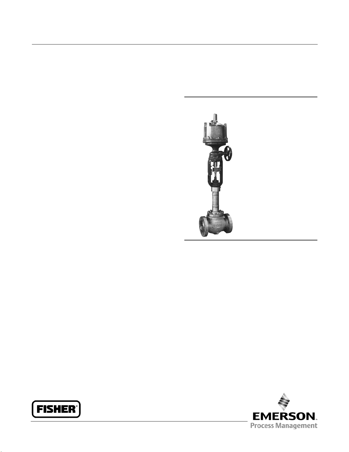
Figure 1. Typical Fisher Cryogenic Valve with
Extension Bonnet and 585C Series Actuator
W6370
Scope of Manual
This instruction manual includes installation, maintenance, and parts information for Fisher EZ-C, ET-C and EWT-C
valves (see figure 1). Refer to separate manuals for instructions covering the actuator and accessories.
Do not install, operate, or maintain EZ-C, ET-C or EWT-C valves without being fully trained and qualified in valve,
actuator, and accessory installation, operation, and maintenance. To avoid personal injury or property damage, it is
important to carefully read, understand, and follow all the contents of this manual, including all safety cautions and
warnings. If you have any questions about these instructions, contact your Emerson Process Management sales office
before proceeding.
Description
EZ-C: globe-style, single-port, unbalanced valves with integral end connections, post guiding, metal-to-metal seating,
and quick-change trim. They feature stainless steel construction materials and fabricated extension bonnets.
ET-C and EWT-C: metal-to-metal seated globe-style, single-port, cage-guided, pressure-balanced valves featuring
stainless steel construction materials and fabricated extension bonnets.
www.Fisher.com
Page 2
EZ-C, ET-C, and EWT-C Valves
October 2014
Table 1. Specifications
Instruction Manual
D102175X012
Valve Sizes
EZ-C: NPS J 1, J 1-1/2, J 2, J 3, and J 4
ET-C: NPS J 3, J 4, J 6, and J 8
EWT-C: NPS J 6X4
(1)
, J 8X4, J 8X6, J 12X6, and
J 10X8
End Connection Styles
(2)
CL150, 300, and 600 raised-face flanges per ASME
Material Temperature Capability
EZ-C: -198 to 149_C(-325to300_F)
ET-C and EWT-C:
-198 to 66_C(-325to150_F)
Maximum Allowable Actuator Thrust
See table 2
(2)
B16.5
Flow Characteristics
Maximum Inlet Pressure
(2)
CL150 and 300–Valves are consistent with
EZ-C: Equal percentage, linear, and
quick opening
ET-C and EWT-C: Equal percentage and linear
pressure-temperature ratings per ASME B16.34
CL600–Valves with B8M Class 2 bolting are
consistent with CL600 pressure-temperature ratings
per ASME B16.34 except as shown below:
EZ-C VALVES
Valve Size, NPS
1
2
3
Maximum InletPressure
Bar Psig
77
83
94
1110
1200
1370
Flow Directions
EZ-C:Up through the seat ring only
ET-C and EWT-C
:
Normally down
Approximate Weights
EZ-C:
NPS 1: 11 kg (33 lb)
(4)
NPS 1-1/2: 23 kg (48 lb)
ET-C AND EWT-C VALVES
Valve Size, NPS
3 94 1370
6, 8 x 6, 12 x 6 75 1085
8, 10 x 8 96 1390
Maximum InletPressure
Bar Psig
NPS 2: 41 kg (90 lb)
NPS 3: 60 kg (130 lb)
NPS 4: 95 kg (210 lb)
ET-C:
NPS 3: 51 kg (135 lb)
CL600–Valves with optional S20910 (XM-19) bolting
are consistent with CL600 pressure-temperature
ratings per ASME B16.34
NPS 4: 95 kg (210 lb)
NPS 6: 211kg(465lb)
NPS 8: 372kg(820lb)
Shutoff Classifications per ANSI/FCI 70-2
and IEC 60534-4
EWT-C
NPS 6X4: 200 kg (440 lb)
VALVE SHUTOFF CLASS
EZ-C
ET-C and EWT-C
1. Valvesize number is end connectionsize by normal trim size.For example, an NPS 6X4 valve has NPS 6 end connections with NPS 4 trim.
2. Do not exceed the pressure/temperature limits in this manualand any applicable code limitation.
3. ClassV Air Test is optional. Test will be 50psid air. Class V shutoffcannot be performed with water. The residual trappedmoisture from testing with water can cause valve and trim damage
from ice crystals formed at below freezingservice temperatures.
4. Down is in through the cage and out the seal ring. (see figure 9).
Class IV–Standard
Class VI–Optional
Class IV–Standard
Class V Air Test
–Optional
(3)
NPS 8X4: 277 kg (610 lb)
NPS 8X6: 318 kg (700 lb)
NPS 12X6: 730 kg (1610 lb)
NPS 10X8: 753 kg (1660 lb)
2
Page 3
Instruction Manual
D102175X012
EZ-C, ET-C, and EWT-C Valves
Table 2. Maximum Allowable Actuator Thrust for Standard Style 3 Bonnet Extension Length
MAXIMUM ALLOWABLE STEM LOAD
FOR S20910 (XM-19) STEM MATERIAL
VALVE SIZE, NPS
1
1-1/2
2
3
4, 6X4, 8X4
6, 8X6, 12X6
8, 10X8
STEM DIAMETER
mm Inches N Lb
9.5 3/8 5382 1210
12.7 1/2 13166 2960
9.5 3/8 5338 1200
12.7 1/2 13166 2960
12.7 1/2 14367 3230
19.1 3/4 44169 9930
12.7 1/2 15301 3440
19.1 3/4 45459 10220
12.7 1/2 16458 3700
19.1 3/4 46971 10560
19.1 3/4 36385 8180
25.4 1 81487 18320
19.1 3/4 41366 9300
25.4 1 87003 19560
Educational Services
October 2014
For information on available courses for Fisher EZ-C, ET-C, and EWT-C valves, as well as a variety of other products,
contact:
Emerson Process Management
Educational Services - Registration
Phone: 1-641-754-3771 or 1-800-338-8158
E-mail: education@emerson.com
http://www.emersonprocess.com/education
Installation
Isolatethecontrolvalvefromthelinepressure,releasepressure from both sides of the valve body, and drain the
process media from both sides of the valve. Remove actuator supply pressure, and use lockout procedures to be sure
that the above measures stay in effect while you work on the equipment. Refer to the Warnings at the beginning of the
Maintenance section for additional information.
WARNING
Always wear protective gloves, clothing, and eyewear when performing any installation operations to avoid personal
injury.
Personal injury or equipment damage caused by sudden release of pressure may result if the valve assembly is installed
where service conditions could exceed the limits given in table 1 or on the appropriate nameplates. To avoid such injury or
damage, provide a relief valve for over-pressure protection as required by government or accepted industry codes and
good engineering practices.
Check with your process or safety engineer for any additional measures that must be taken to protect against process
media.
If installing into an existing application, also refer to the WARNING at the beginning of the Maintenance section in this
instruction manual.
3
Page 4

EZ-C, ET-C, and EWT-C Valves
October 2014
Instruction Manual
D102175X012
CAUTION
When ordered, the valve configuration and construction materials were selected to meet particular pressure, temperature,
pressure drop, and controlled fluid conditions. Since some valve body/trim material combinations are limited in their
pressure drop and temperature ranges, do not apply any other conditions to the valve without first contacting your
Emerson Process Management sales office.
Before installing the valve, inspect the valve and pipelines for any damage and any foreign material which may cause
product damage.
1. Before installing the valve, inspect the valve and associated equipment for any damage and any foreign material.
2. Make certain the valve body interior is clean, that pipelines are free of foreign material, and that the valve is
orientedsothatpipelineflowisinthesamedirectionasthearrowonthesideofthevalve.
3. Gas Service: The normal method of mounting for gas service is with the actuator vertical above the valve body.
However, the control valve assembly may be installed in any orientation unless limited by seismic criteria. Other
positions may result in uneven valve plug and cage wear that could result in improper operation. For mounting
assistance, consult your Emerson Process Management sales office.
CAUTION
To avoid possible damage to the packing, do not allow the installed actuator angle to be so flat as to allow liquid inside the
bonnet to come in contact with the packing.
Also, if insulation is applied, do not let the insulation run up the extension bonnet. This could cause the packing to freeze
and be damaged.
Liquid Service: The preferred method of mounting for liquid service is with the actuator vertical above the valve body.
This will allow a vapor layer to form between the liquid and the packing. If there are piping constraints, the actuator
can be angled slightly from vertical. However, in no case should the angle be so flat as to allow liquid inside the bonnet
to come in contact with the packing. For mounting assistance, consult your Emerson Process Management sales
office.
4. If insulation is applied, make sure it is applied only to the body/bonnet joint. Do not let the insulation run up the
extension bonnet.
5. Use accepted piping and welding practices when installing the valve in the line. For flanged valve bodies, use a
suitable gasket between the valve body and pipeline flanges.
6. If the actuator and valve are shipped separately, refer to the actuator mounting procedure in the appropriate
actuator instruction manual.
WARNING
Personal injury could result from packing leakage. Valve packing was tightened before shipment; however, the packing
might require some readjustment to meet specific service conditions.
Valves with ENVIRO-SEALt live-loaded packing will not require this initial readjustment. See the Fisher instruction
manual titled ENVIRO-SEAL Packing System for Sliding-Stem Valves for packing instructions. If you wish to convert
your present packing arrangement to ENVIRO-SEAL packing, refer to the retrofit kits listed in the parts kit sub-section
near the end of this manual.
4
Page 5
Instruction Manual
D102175X012
EZ-C, ET-C, and EWT-C Valves
October 2014
Maintenance
Valve parts are subject to normal wear and must be inspected and replaced as necessary. Inspection and maintenance
frequency depends on the severity of service conditions. This section includes instructions for packing maintenance
and trim maintenance. All maintenance operations may be performed with the valve in the line.
WARNING
Avoid personal injury or property damage from sudden release of process pressure. Before performing any maintenance
operations:
D Do not remove the actuator from the valve while the valve is still pressurized.
D Always wear protective gloves, clothing, and eyewear when performing any maintenance operations to avoid personal
injury.
D Disconnect any operating lines providing air pressure, electric power, or a control signal to the actuator. Be sure the
actuator cannot suddenly open or close the valve.
D Use bypass valves or completely shut off the process to isolate the valve from process pressure. Relieve process pressure
from both sides of the valve. Drain the process media from both sides of the valve.
D Vent the pneumatic actuator loading pressure and relieve any actuator spring precompression.
D Use lock-out procedures to be sure that the above measures stay in effect while you work on the equipment.
D The valve packing box may contain process fluids that are pressurized, even when the valve has been removed from the
pipeline. Process fluids may spray out under pressure when removing the packing hardware or packing rings, or when
loosening the packing box pipe plug.
D Check with your process or safety engineer for any additional measures that must be taken to protect against process
media.
CAUTION
Follow instructions carefully to avoid damaging the product surfaces, which could result in damage to the product.
Note
Whenever a gasket seal is disturbed by removing or shifting parts, a new gasket should be installed upon reassembly. This is
necessary to ensure a good gasket seal since the used gasket may not seal properly.
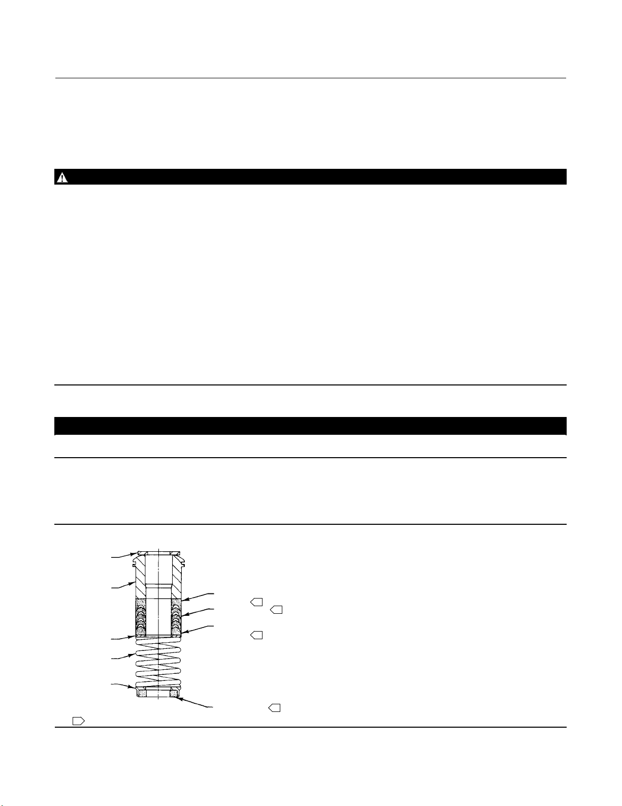
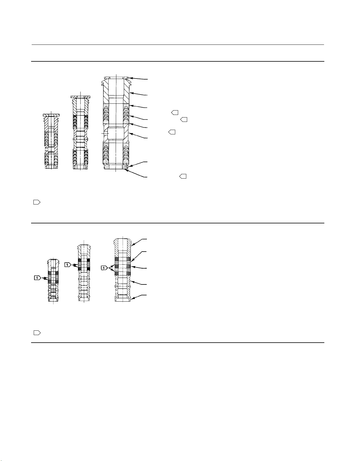
Figure 2. Single PTFE V-Ring Packing Arrangement
UPPER WIPER
(KEY 12)
PACKING
FOLLOWER
(KEY 13)
WASHER
(KEY 10)
SPRING
(KEY 8)
PACKING BOX
RING (KEY 11)
12A7837-A
A6745
NOTE:
1
PACKING SET (KEY6) CONTAINS A FEMALE ADAPTER, V-RING PACKINGRINGS, MALEADAPTER, ANDLOWER WIPERRINGS.
FEMALE
ADAPTER
PACKING RING
MALE
ADAPTER
LOWER WIPER
1
1
1
1
5
Page 6
EZ-C, ET-C, and EWT-C Valves
October 2014
Figure 3. Double PTFE V-Ring Packing Arrangements
UPPER WIPER
(KEY 12)
PACKING
FOLLOWER (KEY 13)
FEMALE
ADAPTER
PACKING RING
MALE
ADAPTER
LANTERN RING
(KEY 8)
PACKING BOX
RING (KEY 11)
9.5 mm
(3/8 INCH)
STEM
NOTE:
PACKING SET(KEY 6) CONTAINS A FEMALE ADAPTER, V-RING PACKING RINGS, MALE ADAPTER, AND LOWER WIPER RINGS.
1
A6746
12.7 mm
(1/2 INCH)
STEM
19.1, 25.4, OR 31.8 mm
(3/4, 1, OR 1-1/4 INCH)
STEM
LOWER WIPER
1
1
1
1
Instruction Manual
D102175X012
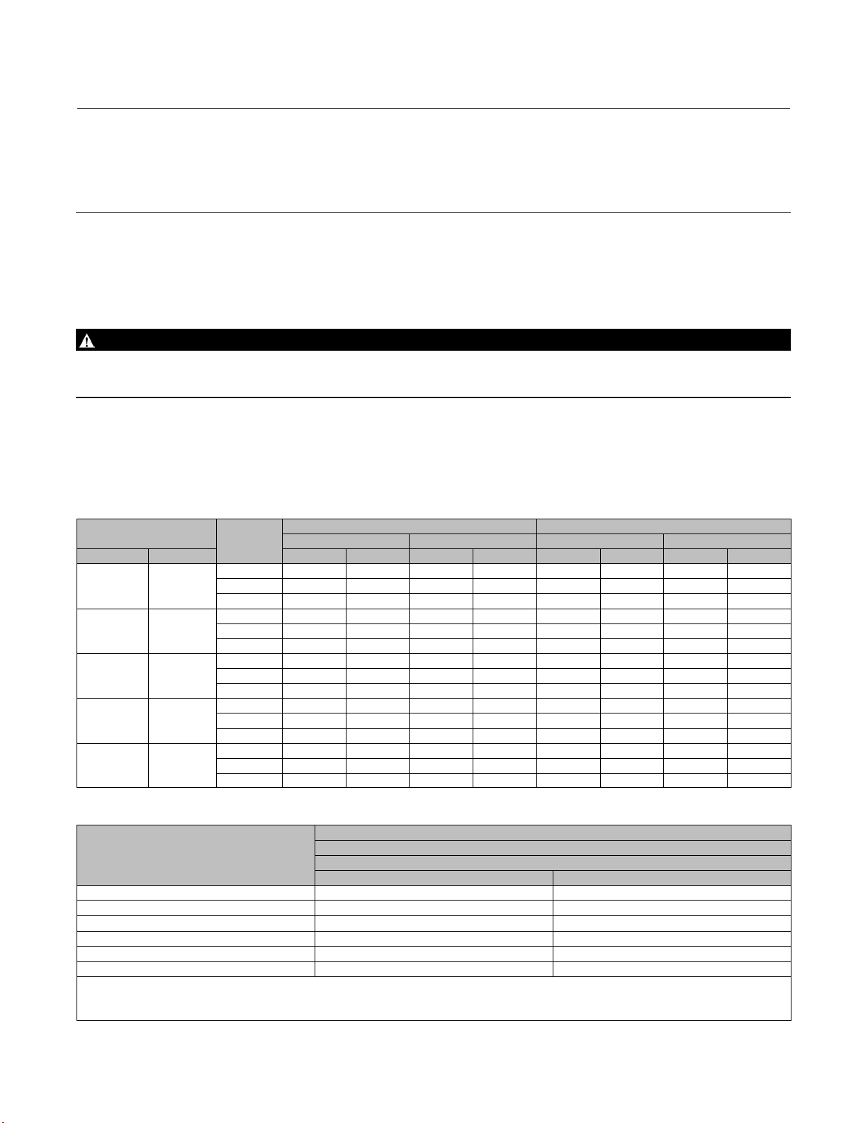
Figure 4. Graphite Ribbon/Filament Packing Arrangements
PACKING
FOLLOWER (KEY13)
GRAPHITE RIBBON
PACKING RING
(KEY 7)
GRAPHITE FILAMENT
PACKING RING
(KEY 7)
LANTERN RING
(KEY 8)
PACKING BOX
RING (KEY 11)
9.5 mm
(3/8 INCH)
STEM
NOTE:
0.102 mm (0.004 INCH) THICKSACRIFICIAL ZINC WASHERS: USE ONLY ONE BELOW EACH GRAPHITERIBBON RING.
1
A6747
12.7 mm
(1/2 INCH)
STEM
19.1, 25.4, OR 31.8 mm
(3/4,1,OR1-1/4INCH)
STEM
6
Page 7

Instruction Manual
D102175X012
EZ-C, ET-C, and EWT-C Valves
October 2014
Packing Maintenance
This section covers PTFE V-ring, double PTFE, and graphite packing used in extension bonnets (figures 2, 3, and 4).
Note
If the valve has ENVIRO-SEAL live-loaded packing installed, refer to the instruction manual ENVIRO-SEAL Packing System for Sliding
Stem Valves for packing instructions. Figure 6 shows typical ENVIRO-SEAL arrangements.
Standard packing key numbers are shown in figures 2, 3, and 4. ENVIRO-SEAL packing key numbers are shown in
figure 6. Bonnet key number locations are shown in figure 7, and valve key numbers are shown in figures 8 and 9.
For spring-loaded single PTFE V-ring packing, the spring (key 8) maintains a sealing force on the packing. If leakage is
noted around the packing follower (key 13), check to be sure the shoulder on the packing follower is touching the
bonnet. If the shoulder is not touching the bonnet, tighten the packing flange nuts (key 5), until the shoulder is against
the bonnet. If leakage cannot be stopped in this manner, proceed with replacing packing procedures.
If there is undesirable packing leakage with other than spring-loaded packing, first try to limit the leakage and
establish a stem seal by tightening the packing flange nuts.
If the packing is relatively new and tight on the stem, and if tightening the packing flange nuts does not stop the
leakage, it is possible that the valve stem is worn or nicked so that a seal cannot be made. The surface finish of a new
valve stem is critical for making a good packing seal. If the leakage comes from the outside diameter of the packing, it
is possible that the leakage is caused by nicks or scratches around the packing box wall. If performing any of the
following procedures, inspect the valve stem and packing box wall for nicks and scratches.
Replacing Packing
WARNING
Refer to the WARNING at the beginning of the Maintenance section in this instruction manual.
Key numbers and sequence of assembly of packing parts are shown in figures 2, 3, and 4. Bonnet key number locations
are shown in figure 7, and valve key number locations are shown in figures 8 and 9, unless otherwise noted.
1. Isolatethecontrolvalvefromthelinepressure,releasepressure from both sides of the valve body, and drain the
process media from both sides of the valve. If using a power actuator, also shut off all pressure lines to the power
actuator,andreleaseallpressurefromtheactuator.Uselock-outprocedurestobesurethattheabovemeasures
stay in effect while you work on the equipment. Observe the Warnings at the start of the Maintenance section.
2. Disconnect the operating lines from the actuator and any leak-off piping from the bonnet. Disconnect the stem
connector and remove the actuator from the valve by unscrewing the yoke locknut (key 15) or hex nuts (key 26, not
shown).
3. Loosen the packing flange nuts (key 5) so that the packing is not tight on the valve stem. Remove any travel
indicator parts and stem locknuts from the valve stem threads.
WARNING
D To avoid personalinjury or property damage caused by uncontrolled movement of the bonnet, loosen the bonnet by
following the instructions in the next steps.
7
Page 8
EZ-C, ET-C, and EWT-C Valves
October 2014
Instruction Manual
D102175X012
Do not remove a stuck bonnet by pulling on it with equipment that can stretch or store energy in any other manner. The
sudden release of stored energy can cause uncontrolled movement of the bonnet.
D To avoid personalinjury or damage to the seating surface caused by the valve plug and stem assembly dropping from
the bonnet after being lifted out of the valve body, observe the following instructions.
4. When lifting an EZ-C bonnet, temporarily install a valve stem locknut on the valve stem. This locknut will prevent
the valve plug and stem assembly from dropping out of the bonnet.
5. When lifting an ET-CorEWT-Cbonnet,be sure the plug and stem assembly and cage remain in the valve body.
WARNING
To avoid possible personal injury, review your process shutdown procedures to be sure process pressure is not applied to
the valve for the following procedure.
6. Hex nuts (key 16) attach the bonnet to the valve body (key 1). Loosen these nuts or cap screws approximately 3 mm
(1/8 inch). Then, loosen the body-to-bonnet joint by either rocking the bonnet or prying between the bonnet and
valve body. Work with a prying tool around the bonnet until the bonnet loosens.
Table 3. Recommended Torque for Packing Flange Nuts
VALVE STEM DIAMETER
mm Inch NSm Lbf-in NSm Lbf-in NSm Lbf-in NSm Lbf-in
9.5 3/8
12.7 1/2
19.1 3/4
25.4 1
31.8 1-1/4
PRESSURE
RATING
150 3 27 5 40 1 13 2 19
300 4 36 6 53 2 17 3 26
600 6 49 8 73 3 23 4 35
150 5 44 8 66 2 21 4 31
300 7 59 10 88 3 28 5 42
600 9 81 14 122 4 39 7 58
150 11 99 17 149 5 47 8 70
300 15 133 23 199 7 64 11 95
600 21 182 31 274 10 87 15 131
150 19 169 29 254 9 80 14 120
300 26 226 38 339 12 108 18 162
600 35 310 53 466 17 149 25 223
150 27 238 40 357 13 113 19 169
300 36 318 54 477 17 152 26 228
600 49 437 74 655 24 209 36 314
Minimum Torque Maximum Torque Minimum Torque Maximum Torque
GRAPHITE PACKING PTFE PACKING
Table 4. Body-to-Bonnet Torque Guidelines
BOLT TORQUES
VALVE SIZE, NPS
NSm Lbf-ft
1 122 90
1-1/2 or 2 91 67
3 163 120
4, 6X4, or 8X4 258 190
6, 8X6, or 12X6 522 385
8or10X8 712 525
1. Determinedfrom laboratory testing.
2. For bolting materials not listed in table 4, contactyour Emerson Process Management salesoffice for torque information.
3. SA193-B8M s train hardened.
4. Hotrolled.
Bolt Material
(3)
B8M
or S20910 (XM-19)
(1)
(2)
(4)
8
Page 9

Instruction Manual
D102175X012
EZ-C, ET-C, and EWT-C Valves
October 2014
D If fluid leaks from the joint, it may indicate that process pressure is applied to the valve. Review your process
shutdown procedures, and be sure process pressure is not
applied to the valve.
D If no fluid leaks from the joint, remove the nuts completely and carefully lift the bonnet off the valve body.
7. For EZ-C valves, removethestemlocknut.Separatethevalveplugandstemfromthebonnet,andsetthepartsona
protective surface to prevent damage to gasket or seating surfaces.
8. For ET-C and EWT-C: If it is necessary to remove and inspect the valve trim, refer to the following Trim Maintenance
section.
9. Remove the bonnet gasket (key 10) and cover the opening in the valve to protect the gasket surface and prevent
foreign material from getting into the valve body cavity.
10. Remove the packing flange nuts, packing flange, upper wiper, and packing follower (keys 5, 3, 12, and 13).
Carefully push out all the remaining packing parts from the valve side of the bonnet using a rounded rod or other
tool that will not scratch the packing box wall. Clean the packing box and metal packing parts.
11. Inspect the valve stem threads and packing box surfaces for any sharp edges which might cut the packing.
Scratches or burrs in the packing box surfaces could cause leakage or damage to the new packing. If the surface
condition cannot be improved by light sanding, replace the damaged parts.
12. If necessary, go to the Trim Maintenance procedures to remove, inspect or replace trim parts. Return to this
sectionwheninstallingthebonnetonthevalvebody.
Installing the Bonnet
13. Remove the covering protecting the valve body cavity and install a new bonnet gasket (key 10), making sure the
gasket seating surfaces are clean and smooth. Then slide the bonnet over the stem and onto the stud bolts (key 15).
Note
Proper performance of the bolting procedures in step 10 compresses the spiral wound gasket (key 12) or load ring (key 26) to both
load and seal the seat ring gasket (key 13). It also compresses the outer edge of the bonnet gasket (key 10) to seal the
body-to-bonnet joint.
The proper bolting procedures in step 14 include, but are not limited to, ensuring that bolting threads are clean and evenly
tightening the cap screws or nuts onto the studs in a crisscross pattern. Tightening one cap screw or nut may loosen an adjacent
cap screw or nut. Repeat the crisscross tightening pattern several times until each cap screw or nut is tight and the body-to-bonnet
seal is made.
Note
Stud(s) and nut(s) should be installed such that the manufacturer's trademark and material grade marking is visible, allowing easy
comparison to the materials selected and documented in the Emerson/Fisher serial card provided with this product.
WARNING
Personal injury or damage to equipment could occur if improper stud and nut materials or parts are used. Do not operate or
assemble this product with stud(s) and nut(s) that are not approved by Emerson/Fisher engineering and/or listed on the
serial card provided with this product. Use of unapproved materials and parts could lead to stresses exceeding the design
or code limits intended for this particular service. Install studs with the material grade and manufacturer's identification
mark visible. Contact your Emerson Process Management representative immediately if a discrepancy between actual
parts and approved parts is suspected.
9
Page 10

EZ-C, ET-C, and EWT-C Valves
October 2014
14. Lubricate the bolting with anti-seize lubricant and install it, using accepted bolting procedures during tightening,
so that the body-to-bonnet joint will withstand test pressures and application service conditions. Use the bolt
torques in table 4 as guidelines.
15. Install new packing and the metal packing box parts according to the appropriate arrangement in figures 2, 3, or 4.
Place a smooth-edged pipe over the valve stem and gently tap each soft packing part into the packing box.
16. Slide the packing follower, upper wiper, and packing flange (keys 12, 13, and 3) into position. Lubricate the
packing flange studs (key 4) and faces of the packing flange nuts (key 5). Install the packing flange nuts.
17. Tightening packing flange nuts (key 5):
a. For spring-loaded PTFE V-ring packing, tighten the packing flange nuts until the shoulder on the packing follower
(key 13) contacts the bonnet.
Instruction Manual
D102175X012
b. For graphite packing, tighten the packing flange nuts to the maximum
Then, loosen the packing flange nuts, and retighten them to the recommended minimum
table 3.
c. For double PTFE V-ring packing, tighten the packing flange nuts alternately in small equal increments until one of
the nuts reaches the minimum recommended torque shown in table 3. Then, tighten the remaining nut until the
packing flange is level and at a 90 degree angle to the valve stem.
d. For ENVIRO-SEAL live-loaded packing, refer to the Fisher instruction manual titled: ENVIRO-SEAL Packing System
for Sliding-Stem Valves.
18. Mount the actuator on the valve assembly and reconnect the actuator and valve stem according to the procedure
in the appropriate actuator instruction manual.
recommended torque shown in table 3.
torque shown in
Trim Maintenance
WARNING
Refer to the WARNING at the beginning of the Maintenance section in this instruction manual.
This procedure describes how the valve trim can be completely disassembled. When inspection or repairs are required,
perform only those steps necessary to accomplish the task. Observe the Warning at the start of the Maintenance
section.
Key number locations are shown in figures8and9,unlessotherwisenoted.
EZ-C Trim Disassembly
Key number locations are shown in figure 8, unless otherwise noted.
1. Remove the actuator and the bonnet according to steps 1 through 9 of the Replacing Packing procedures in the
Maintenance section.
WARNING
To avoid personal injury due to leaking fluids, avoid damaging gasket sealing surfaces.
The surface finish of the valve stem (key 7) is critical for making a good packing seal.
The seating surfaces of the valve plug (key 2) and seat ring (key 9) are critical for proper shutoff.
Protect these surfaces accordingly.
10
Page 11

Instruction Manual
D102175X012
EZ-C, ET-C, and EWT-C Valves
October 2014
Figure 5. Fisher EZ-C Valve Stem Torque and Pin Replacement
D
DIMENSION
16
0.625
19
0.75
25
1
35A5717-C
GROOVE PIN
(KEY 8)
VALVE STEM STEM TORQUE
mm Inch NSm Lbf-ft mm Inch
D
9.5
12.7
19.1
3/8
1/2
3/4
40-47
81-115
237-339
25-35
60-85
175-250
DRILL SIZE,
INCHES
3/32
1/8
3/16
Perform the following steps to remove the valve trim.
Note
With some valve plug sizes and configurations, the seat ring retainer and bushing assembly (keys 3 and 26, figure 7, 8, and 9) will
come out of the valve body with the valve plug and stem assembly, and in other valve plug sizes and configurations, the valve plug
will slide through the seat ring retainer and bushing assembly, leaving the retainer and bushing assembly in the valve body.
2. With the valve plug and stem assembly out of the valve body, either slide the seat ring retainer, bushing assembly
(keys 3 and 26), gaskets, and shim (keys 10, 12, and 25) up over the valve plug and stem or, lift the seat ring retainer
and bushing assembly, associated gaskets, and shim out of thevalvebody.Ifthevalveplugistobereused,protect
the valve plug seating surface to prevent damage.
3. To disassemble the stem, plug, and pin, drive or drill out the pin (key 8) and unscrew the valve stem (key 7) from the
valve plug (key 2).
4. Remove the seat ring and seat ring gasket (keys 9 and 13).
5. Inspect parts for wear or damage that could prevent proper operation of the valve. Clean, inspect and obtain
replacement parts as necessary for reassembly.
EZ-C Trim Assembly
This procedure assumes that all the trim and associated gaskets were removed from the valve body. If these parts were
not all removed, start the assembly procedure at the appropriate step.
CAUTION
To avoid weakening the stem that may cause failure in service, never reuse an old stem with a new valve plug. Using an old
stem with a new plug requires drilling a new pin hole in the stem, which will weaken the stem. However, a used valve plug
may be reused with a new stem.
Key number locations are shown in figure 8, unless otherwise noted.
11
Page 12

EZ-C, ET-C, and EWT-C Valves
October 2014
Instruction Manual
D102175X012
1. Screw the valve stem (key 7) into the valve plug (key 2). Tighten to the torque valve given in figure 5. Refer to figure
5 to select the proper drill size. Drill through the stem using the hole in the valve plug as a guide. Remove any chips
or burrs and drive in a new pin (key 8) to lock the assembly.
2. Install the seat ring gasket (key 13) and seat ring (key 9).
Note
With some valve plug sizes and configurations, the valve plug will slide through the s eat ring retainer and bushing assembly (keys
3 and 26), and in other configurations, it will not.
3. If the valve plug (key 2) will not slide through the seat ring retainer and bushing assembly (keys 3 and 26), proceed
as follows:
a. Place the seat ring retainer and bushing assembly (keys 3 and 26) over the stem of the valve plug and stem
assembly.
b. Install the seat ring retainer and bushing assembly, which also includes the valve plug and stem assembly, on top
of the seat ring, ensuring that the seat ring retainer slips onto the seat ring properly. Any rotational orientation of
the seat ring retainer with respect to the valve body is acceptable.
Table 5. Fisher ET-C and EWT-C Valve Stem Torque and Pin Replacement
VALVE STEM DIAMETER TORQUE, MINIMUM TO MAXIMUM
mm Inches NSm Lbf-ft
9.5 3/8 40-47 25-35 3/32
12.7 1/2 81-115 60-85 1/8
19.1 3/4 238-339 175-250 3/16
25.4 1 421-482 310-355 1/4
31.8 1-1/4 827-908 610-670 1/4
DRILL SIZE, INCHES
c. Place the spiral wound gasket, shim, and bonnet gasket (keys 12, 25, and 10) on the shoulder of the seat ring
retainer.
4. If the valve plug (key 2) will slide through the seat ring retainer and bushing assembly (keys 3 and 26), proceed as
follows:
a. Install the seat ring retainer and bushing assembly on top of the seat ring, ensuring that the seat ring retainer
slips onto the seat ring properly. Any rotational orientation of the seat ring retainer with respect to the valve
body is acceptable.
b. Place the spiral wound gasket, shim, and bonnet gasket (keys 12, 25, and 10) on the shoulder of the seat ring
retainer.
c. Slide the valve plug and stem assembly or the valve plug guide and stem assembly into the seat ring retainer and
bushing assembly (keys 3 and 26).
5. Mount the bonnet on the valve body and complete assembly using the Replacing Packing procedures in the
Maintenance section.
6. If the valve has soft metal-to-metal seats, refer to the Coining Soft Metal-to-Metal Seats section.
ET-C and EWT-C Trim Disassembly
Key number locations are shown in figure 9, unless otherwise noted.
12
Page 13

Instruction Manual
D102175X012
EZ-C, ET-C, and EWT-C Valves
October 2014
1. Remove the actuator and the bonnet according to steps 1 through 9 of the Replacing Packing procedure in the
Maintenance section.
WARNING
To avoid personal injury due to leaking fluids, avoid damaging gasket sealing surfaces.
The surface finish of the valve stem (key 7) is critical for making a good packing seal.
The inside surface of the cage (key 3) is critical for tight shutoff and smooth operation of the valve plug.
The seating surfaces of the valve plug (key 2) and seat ring (key 9) are critical for proper shutoff.
Protect these surfaces accordingly.
Perform the following steps to remove the valve trim.
2. Remove the load ring (key 26) from an NPS 8 ET-C or NPS 10X8 EWT-C valve, and wrap it for protection.
3. Remove the plug and stem assembly from the valve body. The cage (key 3) might come out of the valve body with
the plug, due to seal ring friction.
a. If so, carefully separate the cage from the plug and stem assembly.
b. Ifthecagewasnot
removedfromthevalvebodywiththeplugandstemassembly,removeit,theassociated
gaskets (keys 10 and 12), and shim (key 51).
4. Remove the seat ring (key 9) and seat ring gasket (key 13). Composition seat constructions use a disk (key 23)
sandwiched between a disk seat (key 22) and disk retainer (key 21).
5. Clean, inspect, and if necessary obtain replacement parts.
ET-C an d EWT-C Valve Plug Maintenance
CAUTION
To avoid the valve plug seal ring (key 28) not sealing properly and affecting valve performance, be careful not to scratch the
surfaces of the ring groove on the valve plug or any of the surfaces of the replacement ring.
1. With the valve plug (key 2) removed, according to the disassembly portion of the Trim Maintenance procedure,
proceed as follows:
2. The spring-loaded seal ring may be removed by first working the retaining ring (key 27) off with a screwdriver. Then
carefully slide the metal backup ring (key 29) and seal ring (key 28) off the valve plug (key 2).
3. A spring-loaded seal ring must be installed so that its open side faces toward the valve stem, or toward the seat of
the plug depending on flow direction, as shown in view A of figure 9. To install a spring-loaded seal ring, slide the
seal ring (key 28) onto the valve plug followed by the metal backup ring (key 29).
4. Then install the retaining ring (key 27) by inserting one end in the groove and, while turning the plug, press the ring
into the groove. Again, be careful not to scratch any surfaces of the ring or plug.
CAUTION
To avoid weakening the stem that may cause failure in service, never reuse an old stem with a new valve plug. Using an old
stem with a new plug requires drilling a new pin hole in the stem, which will weaken the stem. However, a used valve plug
may be reused with a new stem.
13
Page 14

EZ-C, ET-C, and EWT-C Valves
October 2014
5. Toreplacethevalvestem(key7),driveordrilloutthepin(key8).Unscrewthevalveplugfromthestem.
6. Screwthenewstemintothevalveplug.Tightentothetorquevaluegivenintable5.Refertotable5toselectthe
properdrillsize.Drillthroughthestemusingtheholeinthevalveplugasaguide.Removeanychipsorburrsand
drive in a new pin to lock the assembly.
Instruction Manual
D102175X012
ET-C and EWT-C Trim Assembly
Key number locations are shown in figure 9, unless otherwise noted.
1. Install the seat ring gasket (key 13), and seat ring (key 9) or disk seat (key 22). With composition seat constructions,
install the disk (key 23) and disk retainer (key 21).
2. Install the cage (key 3). Any rotational orientation of the cage with respect to the valve body is acceptable.
3. Lower the valve plug (key 2) and stem assembly into the cage. Make sure the seal ring (key 28) is evenly engaged in
theentrancechamferatthetopofthecage(key3)toavoiddamagingthering.
4. Place the gaskets (keys 12 and 10) and the shim (key 51) on top of the cage.
5. With an NPS 8 ET-C or NPS 10X8 EWT-C valve, install the load ring (key 26).
6. Mount the bonnet on the valve body and complete assembly using the Replacing Packing procedures in the
Maintenance section. Torque guidelines for body-to-bonnet bolting are shown in table 4.
7. If the valve has soft metal-to-metal seats, refer to the Coining Soft Metal-to-Metal Seats section, below.
Coining Soft Metal-to-Metal Seats
Soft metal-to-metal seat constructions consist of a valve plug with hardfaced CoCr-A seat and a non-hardfaced S31600
seat ring. For optimum shutoff performance of these constructions, coin seats by stroking the valve plug into the seat
ring at least three times with maximum actuator force.
CAUTION
To avoid possible product damage which may affect performance, do not lap soft metal-to-metal seats.
Parts Ordering
Each body-bonnet assembly is assigned a serial number which can be found on the valve. This same number also
appears on the actuator nameplate when the valve is shipped from the factory as part of a control valve assembly.
Refer to the serial number when contacting your Emerson Process Management sales office for technical assistance.
When ordering replacement parts, refer to the serial number and to the eleven-character part number for each part
required from the following parts kit or parts list information.
WARNING
Use only genuine Fisher replacement parts. Components that are not supplied by Emerson Process Management should
not, under any circumstances, be used in any Fisher valve, because they may void your warranty, might adversely affect the
performance of the valve, and could cause personal injury and property damage.
14
Page 15

Instruction Manual
D102175X012
EZ-C, ET-C, and EWT-C Valves
Parts Kits
Gasket Kits
Includes keys 10, 12, 13, and 25 for EZ-C valves. Includes keys 10, 12, 13, and 51 for ET-C and EWT-C valves.
VALVE SIZE, NPS KIT PART NUMBER
1 RGASKETX162
1-1/2 RGASKETX172
2 RGASKETX182
3 RGASKETX202
4, 6X4, 8X4 RGASKETX212
6 RGASKETX222
8X6, 12X6 RGASKETX392
8, 10X8 RGASKETX232
Packing Kits
October 2014
Packing kits for standard packing includes keys 6, 8, 10, 11, and 12. Packing kits do not apply to N10276, N08020, or
N04400 trims.
Standard Packing Repair Kits (Non Live-Loaded)
Stem Diameter, mm (Inches)
Yoke Boss Diameter, mm (Inches)
PTFE (Contains keys 6, 8, 10, 11, and 12) RPACKX00012 RPACKX00022 RPACKX00032 RPACKX00342
Double PTFE (Contains k eys 6, 8, 11, and 12) RPACKX00042 RPACKX00052 RPACKX00062 RPACKX00362
Single Graphite Ribbon/Filament (Contains keys 7 [ribbon ring],
7 [filament ring], 8, and 11)
Single Graphite Ribbon/Filament (Contains keys 7 [ribbon ring],
7 [filament ring], and 11)
Single Graphite Ribbon/Filament (Contains keys 7 [ribbon ring],
7 [filament ring])
Double GraphiteRibbon/Filament (Contains keys 7 [ribbon ring],
7 [filament ring], 8, and 11)
9.5 (3/8)
54 (2-1/8)
RPACKX00102 RPACKX00112 RPACKX00122 ---
--- --- --- RPACKX00532
RPACKX00132 RPACKX00142 RPACKX00152 ---
RPACKX00162 RPACKX00172 RPACKX00182 ---
12.7 (1/2)
71 (2-13/16)
19.1 (3/4)
90 (3-9/16)
25.4 (1)
127 (5)
ENVIRO-SEAL Packing Retrofit Kits
Retrofit kits include parts to convert valves with existing standard bonnets to the ENVIRO-SEAL packing box
construction. Refer to figure 6 for key numbers for PTFE and Graphite ULF packing.
Stems and packing box constructions that do not meet Fisher stem finish specifications, dimensional tolerances, and
design specifications, may adversely alter the performance of this packing kit.
ENVIRO-SEAL Packing Retrofit Kits
PACKING
MATERIAL
Double PTFE RPACKXRT012 RPACKXRT022 RPACKXRT032 RPACKXRT042
Graphite ULF RPACKXRT262 RPACKXRT272 RPACKXRT282 RPACKXRT292
Duplex RPACKXRT212 RPACKXRT222 RPACKXRT232 RPACKXRT242
9.5 (3/8)
54 (2-1/8)
STEM DIAMETERAND YOKE BOSS DIAMETER, mm (INCH)
12.7 (1/2)
71 (2-13/16)
19.1 (3/4)
90 (3-9/16)
25.4 (1)
127 (5)
15
Page 16

EZ-C, ET-C, and EWT-C Valves
October 2014
Instruction Manual
D102175X012
ENVIRO-SEAL P acking Repair Kits
Repair kits include parts to replace the “soft” packing materials in valves that already have ENVIRO-SEAL packing
arrangements installed or in valves that have been upgraded with ENVIRO-SEAL retrofit kits. Refer to figure 6 for key
numbers for PTFE and Graphite ULF packing.
Stems and packing box constructions that do not meet Fisher stem finish specifications, dimensional tolerances, and
design specifications, may adversely alter the performance of this packing kit.
ENVIRO-SEAL Packing Repair Kits
Stem Diameter, mm (Inches)
Yoke Boss Diameter, mm (Inches)
Double PTFE(Contains keys 214, 215, & 218) RPACKX00192 RPACKX00202 RPACKX00212 RPACKX00222
Graphite ULF (Contains keys 207, 208, 209, 210, and 214) RPACKX00592 RPACKX00602 RPACKX00612 RPACKX00622
Duplex (Contains keys 207, 209, 214, and215) RPACKX00292 RPACKX00302 RPACKX00312 RPACKX00322
Figure 6. ENVIRO-SEAL Packing System
9.5 (3/8)
54 (2-1/8)
12.7 (1/2)
71 (2-13/16)
19.1 (3/4)
90 (3-9/16)
25.4 (1)
127 (5)
APPLY LUBRICANT
A6362/G1
16
PTFE PACKING ARRANGEMENT
APPLY LUBRICANT
39B4612/A
GRAPHITE ULF PACKING ARRANGEMENT
Page 17

Instruction Manual
D102175X012
Figure 7. Extension Bonnet Assembly
EZ-C, ET-C, and EWT-C Valves
October 2014
44B8565-A
NOTE:
KEY 6 CONTAINS SEVERAL PARTS;REFER TO FIGURES 2, 3, AND 4 FOR PACKING ARRANGEMENTS.
1
Keys 6* and 7* Packing Box Parts
DESCRIPTION
PTFE
V-Ring
Packing
Graphite
Ribbon/F
ilament
Packing
1. Key 6 for double construction containsone extra packing ring for the 9.5 mm (3/8inch) stem, and one extra lower wiper for allsizes. Discard upon assembly.
*Recommended spare parts
Packing Set, PTFE (1 req'd for single, 2 req'd for
double)
(1)
Graphite RibbonRing (2 req'd) 7 1V3160X0022 1V3802X0022 1V2396X0022 1U6768X0022
Graphite Filament Ring 7 1F3370X0322 1E3190X0222 1E3191X0282 1D7518X0132
Quantity Required --- 2 2 3 3
KEY
NO.
9.5 (3/8) 12.7 (1/2) 19.1 (3/4) 25.4 (1)
6 1R290001012 1R290201012 1R290401012 1R290601012
STEM DIAMETER, mm (INCHES)
17
Page 18

EZ-C, ET-C, and EWT-C Valves
October 2014
Parts List
Instruction Manual
D102175X012
Key Description Part Number
Note
Part numbers are shown for recommended spares only.For part
numbers not shown, contact your Emerson Process Management sales
office.
Bonnet Parts (figure 7)
Key Description Part Number
1 Bonnet
If you need a bonnet as a replacement part, order by
valve size and stem diameter, serial number, and
desired material.
2 Bushing
3 Packing Flange
4 Packing Flange Stud
5 Packing Flange Nut
6* Single V-Ring Packing Set See following table
7* Individual Packing Ring See following table
8 Packing BoxRing or Lantern Ring
10 Special Washer
11 Packing Box Ring
12* Upper Wiper, felt
9.5 mm (3/8 inch) stem 1J872606332
12.7 mm (1/2 inch) stem 1J872706332
19.1 mm (3/4 inch) stem 1J872806332
25.4 mm (1-inch) stem 1J872906332
13 Packing Follower
14 Pipe Plug
15 Yoke Locknut
25 Cap Screw
26 Hex Nut
35 Retaining Ring
EZ-C Valve Body Parts (figure 8)
Note
Part numbers are shown for recommended spares only.For part
numbers not shown, contact your Emerson Process Management sales
office.
Key Description Part Number
1ValveBody
If you need a valve body as a replacement
part, orderby valve size, serial number,
and desired material.
2* Valve Plug See following table
3* Seat Ring Retainer, CF8M (316 SST)
(Part numbers for Seat Ring Retainer/Bushing Assemblies are
provided in a following table)
NPS 1 25A6683X022
NPS 1-1/2 25A6685X022
NPS 2 25A6687X022
NPS 3 25A6689X022
NPS 4 35A6691X022
7* Stem See following table
8* Pin See following table
9* Seat Ring See following table
10* Bonnet Gasket, S31600/graphite
NPS 1 1R2859X0042
NPS 1-1/2 1R3101X0032
NPS 2 1R3299X0042
NPS 3 1R3484X0042
NPS 4 1R3724X0042
12* Gasket, N06600/graphite
NPS 1 1R286099442
NPS 1-1/2 1R309999442
NPS 2 1R329799442
NPS 3 1R348299442
NPS 4 1R372299442
13* Seat Ring Gasket, S31600/graphite
NPS 1 1R2862X0062
NPS 1-1/2 1R3098X0052
NPS 2 1R3296X0042
NPS 3 1R3481X0052
NPS 4 1J5047X0062
15 Stud Bolt
16 Hex Nut
18 Flow Arrow
19 Drive Screw
25* Shim, S31600
NPS 1 16A1936X012
NPS 1-1/2 16A1937X012
NPS 2 16A1938X012
NPS 3 16A1940X012
NPS 4 16A1941X012
26* Bushing, R30006 (alloy 6)
(Part number for Seat Ring Retainer/Bushing Assemblies are
provided in a following table)
NPS 1 15A6508X022
NPS 1-1/2 15A7511X022
NPS 2, restricted port 15A6509X022
NPS 2, full port 15A6510X022
NPS 3 15A7491X022
NPS 4, restricted port 15A5712X022
NPS 4, full port 15A6511X022
33 Nameplate
- - - Warning Plate
34 Wire
55 Lubricant, anti-seize - - -
(not included with valve)
18
*Recommended spare parts
Page 19

Instruction Manual
D102175X012
Figure 8. Fisher EZ-C Valve Assembly
EZ-C, ET-C, and EWT-C Valves
October 2014
16A1943-A
GASKET DETAIL
APPLY LUBRICANT
NOTE:
EZ-C KEY NUMBERS NOT SHOWN ARE: 18,19, 33, AND 34.
44B8573-B
19
Page 20

EZ-C, ET-C, and EWT-C Valves
Instruction Manual
October 2014
Key 2* Fisher EZ-C Equal Percentage (Including Micro-Form), Linear, and Quick-Opening Valve Plugs
VALVE STEM
CONNECTION
S31600 w/CoCr-A (alloy 6)
15A6663X012 15A6664X012
9.5 3/8
16A5714X012 16A5712X012
12.7 1/2
9.5 3/8 15A6516X012 15A6517X012
12.7 1/2 15A6518X012 15A6519X012
9.5 3/8 15A6614X012 15A6615X012
12.7 1/2 15A6616X012 15A6617X012
9.5 3/8 15A6634X012 15A6635X012
12.7 1/2 15A6636X012 15A6637X012
9.5 3/8 15A6520X012 15A6521X012
12.7 1/2 15A6522X012 15A6523X012
9.5 3/8 15A6618X012 15A6619X012
12.7 1/2 15A6620X012 15A6621X012
9.5 3/8 15A6638X012 15A6639X012
12.7 1/2 15A6640X012 15A6641X012
12.7 1/2 15A6524X012 15A6525X012
19.1 3/4 15A6526X012 15A6527X012
12.7 1/2 15A6622X012 15A6623X012
19.1 3/4 15A6624X012 15A6625X012
12.7 1/2 15A6642X012 15A6643X012
19.1 3/4 15A6644X012 15A6645X012
12.7 1/2 15A6528X012 15A6529X012
19.1 3/4 15A6530X012 15A6531X012
12.7 1/2 15A6626X012 15A6627X012
19.1 3/4 15A6628X012 15A6629X012
12.7 1/2 15A6646X012 15A6647X012
19.1 3/4 15A6648X012 15A6649X012
12.7 1/2 15A6532X012 15A6533X012
19.1 3/4 15A6534X012 15A6535X012
12.7 1/2 15A6630X012 15A6631X012
19.1 3/4 15A6632X012 15A6633X012
12.7 1/2 15A6650X012 15A6651X012
19.1 3/4 15A6652X012 15A6653X012
VALVE PLUGMATERIAL
S31600 w/CoCr-A
Seat
VALVE SIZE, NPS VALVE PLUG STYLE
Micro-Form
1, 1-1/2 and 2
Quick Opening
Linear
Equal Percentage
Quick Opening
1-1/2
2, 3, 4
3
4
Linear
Equal Percentage
Quick Opening
Linear
Equal Percentage
Quick Opening
Linear
Equal Percentage
Quick Opening
Linear
Equal Percentage
PORT DIAMETER
mm Inch mm Inch
6.4 0.25
9.5 0.375 16A5713X012 16A5711X012
12.7 0.5 15A6659X012 15A6660X012
19.1 0.75 16A3337X012 16A3339X012
9.5 0.375
12.7 0.5 15A6661X012 15A6662X012
19.1 0.75 16A3338X012 16A3340X012
25.4 1
38.1 1.5
50.8 2
76.2 3
101.6 4
D102175X012
Seat and Guide
Key 3*, 26* Fisher EZ-C Seat Ring Retainer and Bushing Assembly
VALVE SIZE, NPS PART NUMBER
1 25A6683X072
1-1/2 25A6685X082
2
3 25A6689X132
4
20
Full Port 25A6687X112
Restricted Port 25A6687X132
Full Port 35A6691X082
Restricted Port ---
*Recommended spare parts
Page 21

Instruction Manual
EZ-C, ET-C, and EWT-C Valves
D102175X012
Key7*FisherEZ-CValveStem,S20910(UseW/Group1Actuators)
VALVE SIZE, NPS
1 and 1-1/2 10A8823XM72 10A8840XBC2 11A2318X622 ---
2 --- 10A8840XBD2 11A2318X632 10B9265XBC2
3 --- 10A8840XBE2 --- 10A9265XBD2
4 --- 1U2307X0012 --- 10A9265XBE2
9.5 mm (3/8 Inch) 12.7 mm (1/2 Inch) 12.7 x 9.5 mm (1/2 x 3/8Inch) 19.1 mm (3/4 Inch)
STEM DIAMETER
Key 8* Fisher EZ-C Pin, S31600
VALVE SIZE, NPS VALVE PLUG STYLE
1 and 1-1/2
2
3 All
4
Micro-Form, Linear, Equal Percentage a nd Quick
Opening
Linear, Equal Percentage and Quick Opening (full
capacity)
Micro-Form, Linear, Equal Percentage a nd Quick
Opening (restricted capacity)
Full Capacity
Restricted Capacity
VALVE STEM CONNECTION
mm Inch
9.5
12.7
12.7
19.1
9.5
12.7
12.7
19.1
12.7
19.1
12.7
19.1
3/8
1/2
1/2
3/4
3/8
1/2
1/2
3/4
1/2
3/4
1/2
3/4
October 2014
PART NUMBER
1B599335072
1D5423X00B2
1B599835072
1B813635072
1B599335072
1D5423X00B2
1B599835072
1B813635072
1B599835072
1B813635072
1B599335072
1F723635072
Key 9* Fisher EZ-C Valve Seat Ring, S31600
VALVE
SIZE,
NPS
1 24B7585X012 24B8298X012 24B8299X012 24B8300X012 24B8301X012 --- --- --- ---
1-1/2 24B6344X012 24B7586X012 24B7213X012 24B7214X012 24B7215X012 24B7216X012 --- --- ---
2 24B8555X012 24B8556X012 24B8557X012 24B8558X012 24B8559X012 --- 24B8560X012 --- ---
3 --- --- --- --- --- --- 24B8561X012 24B8562X012 ---
4 --- --- --- --- --- --- 24B8510X012 --- 24B8563X012
6.4 mm
(0.25 Inch)
9.5 mm
(0.375 Inch)
12.7 mm
(0.5 Inch)
19.1 mm
(0.75 Inch)
PORT DIAMETER
25.1 mm
(1 Inch)
38.1 mm
(1.5 Inch)
50.8 mm
(2 Inch)
76.2 mm
(3 Inch)
101.6 mm
(4 Inch)
*Recommended spare parts
21
Page 22

EZ-C, ET-C, and EWT-C Valves
October 2014
Instruction Manual
D102175X012
ET-C and EWT-C Valve Body Parts (figure 9)
Note
Part numbers are shown for recommended spares only.For part
numbers not shown, contact your Emerson Process Management sales
office.
Key Description Part Number
1ValveBody
If youneed a valve body as a replacement part, order by
valve size, serial number, and desired material.
2* Valve Plug See following table
3* Cage, CF8M(316 SST)/Chrome coat
Equal Percentage
NPS 3 39B0341X012
NPS 4, 6X4, 8X4 39B0343X012
NPS 6, 8X6, 12X6 39B0345X012
NPS 8, 10X8 39B0347X012
Linear
NPS 3 39B0342X012
NPS 4, 6X4, 8X4 39B0344X012
NPS 6, 8X6, 12X6 39B0346X012
NPS 8, 10X8 39B0348X012
7* Stem See following table
8* Pin, S31600
9.5 mm (3/8 inch) stem 1V322635072
12.7 mm (1/2 inch) stem 1V322735072
19.1 mm (3/4 inch) stem 1V326035072
25.4 mm (1-inch), & 38.1 mm (1-1/4inch) stem 1V334035072
9* Seat Ring, w/metal seat, 316 SST
ET-C
NPS 3 23B6127X032
NPS 4 23B6128X052
NPS 6 29A9703X072
NPS 8 29A9704X042
EWT-C
NPS 6X4 23B6129X042
NPS 8X4 23B6130X022
NPS 8X6 20B0811X042
NPS 12X6 33B6131X022
NPS 10X8 29A9704X042
10* Bonnet Gasket, S31600/graphite
NPS 3 1R3484X0042
NPS 4, 6X4, 8X4 1R3724X0042
NPS 6, 8X6, 12X6 1U5081X0052
NPS 8, 10X8 10A3265X112
Key Description Part Number
12* Spiral Gasket, N06600/graphite
NPS 3 1R348299442
NPS 4, 6X4, 8X4 1R372299442
NPS 6, 8X6, 12X6 1U508599442
13* Seat Ring Gasket
NPS 3,S31600/graphite 1R3481X0052
NPS 4, 6X4, 8X4, S31600/graphite 1J5047X0062
NPS 6,S31600/graphite 1U5086X0032
NPS 8X6,12X6, N06600/graphite 1V644199442
NPS 8,10X8, S31600/graphite 10A3266X082
15 Stud Bolt
16 Hex Nut
18 Flow Arrow
19 Drive Screw
21* Disk Retainer, w/Composition Seat, 316 SST
NPS 3 1V711235072
NPS 4, 6X4, 8X4 1V711533092
NPS 6 1V711833092
NPS 8, 10X8 10A4466X012
22* Disk Seat, w/Composition Seat,316 SST
ET-C
NPS 3 1V711435072
NPS 4 1V711733092
NPS 6 1V712033092
NPS 8 20A4467X012
EWT-C
NPS 6X4 1V712533092
NPS 8X4 1V712633092
NPS 8X6 2V721733092
NPS 12X6 2V712733092
NPS 10X8 20A4467X012
23* Disk, PCTFE
NPS 3 18A8539X012
NPS 4, 6X4, 8X4 18A0732X012
NPS 6, 8X6, 12X6 18A0733X012
NPS 8, 10X8 20A4468X042
26 Load Ring
27 Retaining Ring
28* Seal Ring, R30003/UHMWPE
NPS 3 14B8251X012
NPS 4, 6X4, 8X4 14B8252X012
NPS 6, 8X6, 12X6 14B8254X012
NPS 8, 10X8 14B8255X012
29 Back-Up Ring
51* Shim, S31600
NPS 3 16A1940X012
NPS 4,6x4, 8x4 16A1941X012
NPS 6, 8X6, 12X6 16A1942X012
53 Nameplate
55 Lubricant, anti-seize
(not included with valve) - - -
22
*Recommended spare parts
Page 23

Instruction Manual
D102175X012
Figure 9. Fisher ET-C and EWT-C Valve Assembly
EZ-C, ET-C, and EWT-C Valves
October 2014
54B8568-C
WHISPER TRIM
FLOW DIRECTION
STD TRIM
CAVITROL TRIM
54B8568-C
FLOW UP
16A1943-A
FLOW DOWN
VIEW A
ALL CONSTRUCTIONS EXCEPT
NPS 8 AND 10X8
54B8568-C
METAL SEAT
COMPOSITION SEAT
54B8579-B
FOR NPS 8 AND 10X8
CONSTRUCTIONS
VIEW B
23
Page 24

EZ-C, ET-C, and EWT-C Valves
October 2014
Instruction Manual
D102175X012
Key 2* Fisher ET-C and EWT-C Valve Plug
SEAT STYLE
VALVE SIZE,
NPS
3 3.4375 87.3 34B8275X012 34B8190X012 34B8288X012 34B8289X012
4, 6X4, 8X4 4.375 111 34B8276X012 34B7639X012 34B8290X012 34B8291X012
6, 8X6, 12X6 7 178
8, 10X8 8 203 34B8280X012 34B8281X012 34B8294X012 34B8296X012
PORT DIAMETER
Inches mm
12.7 mm (1/2 Inch)
Stem
19.1 mm (3/4 Inch)
Stem
34B8278X012 34B8279X012 34B8292X012 34B8293X012
Metal Composition
S31600 w/CoCr-A Seat S31600 Seat
19.1mm(3/4Inch)
Stem
25.4 mm (1-Inch)
Stem
12.7 mm (1/2 Inch)
Stem
19.1 mm (3/4 Inch)
Stem
19.1 mm (3/4 Inch)
Stem
25.4 mm (1-Inch)
Stem
Key 7* Fisher ET-C and EWT-C Valve Stem, S20910
VALVE SIZE, NPS
3
4, 6X4, 8X4
6, 8X6,
12X6
8, 10X8
STEM DIAMETER
mm Inches
12.7
19.1
12.7
19.1
19.1
25.4
25.4
19.1
25.4
1/2
3/4
1/2
3/4
3/4
1
1
3/4
1
ACTUATOR GROUP
1
1
1
1
1
100
101
1
100, 101
S20910
(XM-19)
10A8840XBD2
10A9265XBF2
10A8840XAD2
10A9265XBG2
10A9265XBH2
11A3429XR72
11A3429XR62
10A9265XBJ2
11A3429XR82
*Recommended spare parts
Neither Emerson, Emerson Process Management, nor any of their affiliated entities assumes responsibility for the selection,use or maintenance
of any product. Responsibilityfor proper selection, use, and maintenance of any productremains solely with the purchaser and end user.
Fisher and ENVIRO-SEAL are marks owned by one of the companies in the Emerson Process Management business unit of Emerson Electric Co. Emerson
Process Management, Emerson, and the Emerson logo are trademarks and service marks of Emerson Electric Co. All other marks are the property of their
respective owners.
The contents of this publication are presented for informational purposes only, and while every effort has been made to ensure their accuracy, they arenot
to be construed as warranties or guarantees, express or implied, regarding the products or services described herein or their use or applicability. All sales are
governed by our terms and conditions,which are available upon request. We reserve the rightto modifyor improve the designs or specifications of such
products at any time without notice.
Emerson Process Management
Marshalltown, Iowa 50158 USA
Sorocaba, 18087 Brazil
Chatham, Kent ME4 4QZ UK
Dubai, United Arab Emirates
Singapore 128461 Singapore
www.Fisher.com
24
E 1995, 2014 Fisher Controls International LLC. All rights reserved.
 Loading...