

Page 1
Product Bulletin
EW Valve
D100023X012
51.1:EW
August 2012
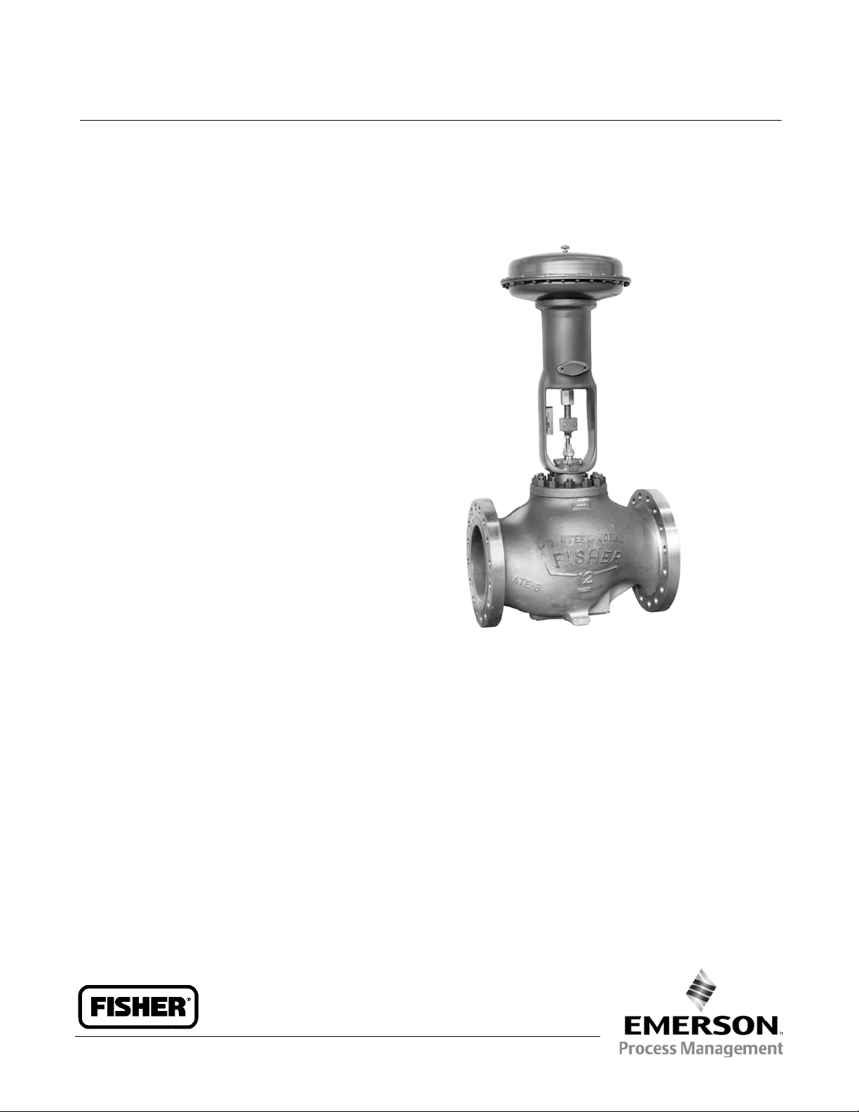
Fisherr EW Series (EWD/EWS/EWT)
Sliding-Stem Control Valves through NPS 12x8
Fisher EW Series easy-et valves (figures 1, 2, 3, and 4)
feature large internal cavities with expanded end
connections and a variety of unbalanced and balanced
plug designs. Sizes available from NPS 4x2
12x8. These combinations provide good fluid control
in economical, high-capacity valve bodies that keep
valve outlet velocities within practical limits.
These valves meet a variety of service requirements,
such as power plants where oversized piping is used to
limit fluid flow velocity. They also perform well in noise
abatement applications; for example, high-pressure
gasreducingstationswheresonicvelocitiesareoften
encountered at the outlet of conventional valve
bodies.
(1)
through
The Fisher EW product line is available for a wide range
of applications, including sulfide and chloride
stress-cracking environments common to the oil and
gas production industries. To discuss available
constructions, contact your Emerson Process
Management sales office and include the applicable
codes and standards required for these environments.
The easy-e Valve Family
EW Series valves are part of the versatile easy-efamily
of Fisher industrial control valves. easy-evalvesshare
the following characteristics:
Multiple trim material choices
Trim temperature capability with metal seats
standard to 427_C(800_F)
Interchangeable, restricted-capacity trims and
full-size trims to match variable process flow
demands
W2777-3
Different cage/plug styles that provide particular
flow characteristics for highly-specialized
applications. The standard cage comes in three
different flow characteristics:
D quick-opening
D linear
D equal percentage
Cavitrolt III cages are available to eliminate
cavitation damage and Whisper Trimt III cages are
available to help attenuate aerodynamic noise.
316 stainless steel packing box parts are standard
(including packing flange, studs, and nuts)
The temperature limits of EWT valves can be extended
above 232_C(450_F) by using PEEK
www.Fisher.com
Page 2

Product Bulletin
51.1:EW
August 2012
EW Valve
D100023X012
(PolyEtherEtherKetone) anti-extrusion rings in
combination with a spring-loaded PTFE seal. The PEEK
anti-extrusion rings expand to close off the clearance
gapbetweentheplugandthecagewherethePTFE
seal may extrude at high temperatures and pressures.
The temperature limits are extended to 316_C (600_F)
for non-oxidizing service and to 260_C(500_F) for
oxidizing service.
Note
Refer to Fisher bulletin 51.1:EWN (D100024X012) for
information on EWN Series valves with Whisper Trim III
cages.
Note
Refer to Fisher bulletin 80.3:010 (D102362X012) for
information on WhisperFlot Aerodynamic Noise
Attenuation Trim.
Features
Compliance with the Clean Air Act– ENVIRO-SEAL™
packing systems provide an improved stem seal to
help prevent the loss of valuable or hazardous
process fluid. The ENVIRO-SEAL packing systems
featurePTFEorGraphiteULFpackingwith
live-loading for reduced packing maintenance.
Piping Economy–Expanded end connections of EW
Series valve bodies may reduce the need for line
swages while accommodating oversized piping
arrangements used to limit fluid flow velocities.
Temperature C ompensation–On designs with the
seat ring threaded into the valve body (figure 4), the
hung cage feature helps reduce gasketing problems
caused by thermal expansion and contraction of
long parts, such as the cage assembly.
Standard Trim Parts across the easy-e product
line–Included are FGM gaskets, packing flange,
studs, and nuts.
High-Temperature, Class IV or Class V
Shutoff–Optional multiple piston rings (figure 14)
for EWD and EWD-1 valve bodies permit Class IV
shutoff up to 593_C (1100_F).
Use of C-seal trim for EWD (see figure 5) permits
Class V shutoff up to 593_C (1100_F).
Increased Pressure/Temperature Ratings–NPS 12x8
CL900 EW Series valve bodies with buttwelding end
connections are capable of increased ASME ratings
called Intermediate Standard Ratings. The extra
strength of the valve body allows these valves to be
used where pressures and temperatures exceed
Standard Class ratings in ASME B16.34.
See Bulletin 59.1:027, Increased Pressure/
Temperature Ratings for EH and EW Series Steel
Valves (D100076X012), for further information.
Noise Attenuation–In an EW Series valve, noise
produced by high flow rates and large pressure
drops can be reduced by up to 18 dbA with a
Whisper Trim I cage, by up to 30 dbA with a Whisper
Trim III cage, and by up to 40 dbA with a WhisperFlo
cage.
Table of Contents
Features 2.....................................
Specifications 3................................
C-seal Trim Description 6........................
ENVIRO-SEAL and HIGH-SEAL Packing Systems 6.....
Available Configurations 10......................
2
Sour Service Capability– Unless otherwise noted,
references are to NACE MR0175-2002. Optional
materials are available to meet NACE MR0103 and
NACE MR0175 / ISO 15156. Material requirements
under these standards vary by edition and year of
issue; the specific standard must be specified.
Material Selection Guidelines 10..................
ANSI/FCI Class VI Shutoff Capabilities 12............
Fisher TSO (Tight Shutoff) Trim Capabilities 13......
Installation 13.................................
Dimensions 29.................................
Page 3

EW Valve
D100023X012
Specifications
Product Bulletin
51.1:EW
August 2012
Valve Body Configurations
See Available Configurations section
Valve Body Sizes
See table 2
End Connection Styles
Flanged:
ring-type joint flanges per ASME B16.5,
J CL150, 300, 600, and 900 raised-face or
J raised-face
per EN 1092-1/B
Buttwelding: Styles per ASME B16.25 schedules that
are consistent with ASME B16.34 are Schedule
or
J 80 for all CL300 and 600 valves, Schedule J 80
or
J XXS for NPS 8x6 CL900 valves, or Schedule
J 80, J 100, or J 120 for NPS 12x8 CL900 valves
Maximum Inlet Pressures and Temperatures
Consistent with applicable J CL300, J 600
J 900 pressure/temperature ratings per
(2)
J 40
(1)
,or
ASME B16.34 unless limited as follows:
Valves With All Except Cavitrol III or Whisper Trim I II
Cages: Where limited by individual
pressure/temperature capabilities in figure 8 or 9 or
temperature capabilities in table 11, 12, 13, or 20.
Valves With Cavitrol III Cages: Where limited by
individual pressure/temperature capabilities in figure
12 or temperature capabilities in table 16 or 20
Valves With Whisper Trim III Cages: Where limited by
individual pressure/temperature capabilities in figure
15, 16, or 17 or temperature capabilities in table 18
or 20
Shutoff Classifications Per ANSI/FCI 70-2andIEC
60534-4
See tables 3 and 4
Construction Materials
Valve, Bonnet, and Bonnet Spacer If Used:
carbon steel,
moly steel,
J LCC carbon steel, J WC9 chrome
J CF8M (316 SST), J other materials
J WCC
upon request
Valve Plug, Cage, and Metal Seating Parts
Valves With All Except Cavitrol III or Whisper Trim III
Cages: See table 5 or 14
Valves With Cavitrol III Cages: See table 15
Valves With Whisper Trim III Cages: See table 17, 18, or
19
All Other Parts: See table 20
Material Temperature Capabilities
(1)
Valve Body/Trim Combinations
Valves With All Except Cavitrol III or Whisper Trim III
Cages: Seefigure8or9andtable11,12,or13
Valves With Cavitrol III Cages: Seefigure12andtable
16
Valves With Whisper Trim III Cages: Seefigure15,16,or
17 and table 18
All Other Parts: See table 20
Flow Characteristics
Standard Ca ges:
J equal percentage
J Quick-opening, J linear, or
Cavitrol and Whisper Trim Cages: Linear
Maximum Pressure Drops
(1, 3)
Same as maximum inlet pressure for specific
construction defined above, except where further
limited as follows:
Valves With All Except Cavitrol III or Whisper Trim I II
Cages: Seefigure8or9
Valves With Cavitrol III Cages: Seefigure12
Valves With Whisper Trim III Cages: Seefigure15,16,
or 17, except where further restricted by the
following max nP/P1 ratio –
J 0.75 for level B cages, J 0.85 for level C cages, or
J 0.99 for level D cages
J 0.60 for level A cages,
(4)
- continued -
Flow Directions
Valves with Standard Cages
EWD, EWD
EWS and EWS-1: Normally up
Valves with Cavitrol Cages: Always down
-
1, EWT, and EWT-1: Normally down
(6)
(5)
Valves with Whisper Trim III Cages: Always up
(5)
(6)
Flow Coefficients and Noise Level Prediction
Refer to Fisher Catalog 12
Port Diameters and Maximum Valve Plug Travels
See table 21
3
Page 4

Product Bulletin
51.1:EW
August 2012
Specifications (continued)
EW Valve
D100023X012
Yoke Boss and Stem Diameters
See table 21
Options
J Lubricator, J lubricator/isolating valve, J drilled
and tapped connection in extension bonnet for
Typical Bonnet Styles (see table 23)
J Plain, J style 1 cast extension, J style 2 cast
extension,
J ENVIRO-SEAL bellows seal bonnet
Packing Arrangements
J Standard PTFE, J Double PTFE, J Graphite,
J ENVIRO-SEAL PTFE, J ENVIRO-SEAL Duplex,
J ENVIRO-SEAL Graphite ULF, J HIGH-SEAL
Approximate Weights
See table 22
1. The pressure/temperaturelimits in this bulletinand any applicable standard or code limitationshould not be exceeded.
2. Certain bonnet boltingmaterialselections may require a CL600 easy-e valve assembly to be derated. Contact yourEmerson Process Management sales officefor more information.
3. Only NPS 12x8CL900valve bodies with threaded (-1) seat rings cantakefull CL900 pressure drops; CL900 valve bodieswith clamped (no dash number) seat rings arelimitedto CL600
pressure drops. Also,there are two different NPS 8x6CL900valve bodies, one for use onlywith Cavitrol III cagesand the other for use with all other constructions.An NPS8x6CL900 valve body
with Cavitrol III cage can take full CL900 pressure drops. For information on other NPS 8x6 constructions that can take full CL900 pressure drops,contactyour Emerson Process Management
sales office. All otherNPS 8x6 constructions are limited to CL600 pressure drops (1440 psid flowing drop) even though installed in a CL900 valve body.
4. Restriction based on excessive noiseifmax nP/P1 ratio for a given cage level is exceeded.
5. Down:in through cage and outthrough seat ring (direction shown in figure 1).
6. Up:in through seatring and out through cage as shown in figure13.
leak-off service,
J valve body drain plug,
J ENVIRO-SEAL bellows seal bonnet for positive stem
sealing of hard-to-handle fluids at temperatures up to
566_C (1000_F),
J style 3 fabricated extension
bonnet made on order to a specific length for
cryogenic service,
J special seismic service bonnet,
J packings suitable for nuclear service, and J forged
bonnet for 5 in. (127 mm) yoke boss on NPS 8x6
CL900 valve,
(450_F) using PEEK anti-extrusion rings
J Class V shutoff for EWT above 232_C
J Class V
shutoff for EWD up to 593_C (1100_F) using C-seal
trim
ENVIRO-SEAL Packing System Specifications
Applicable Stem Diameters
J 19.1 (3/4), J 25.4 (1), and J 31.8 (1-1/4)
diameter valve stems
Maximum Pressure/Temperature Limits
To Meet the EP A Fugitive Emission Standard of 100
(2)
PPM
(1)
For ENVIRO-SEAL PTFE and ENVIRO-SEAL Duplex packing
systems: full CL300 up to 232_C(450_F)
For ENVIRO
-
SEAL Graphite ULF packing system: 1500
psig (104 bar) at 316_C(600_F)
Construction Materials
PTFE Packing Systems:
Packing Ring and Lower Wiper: PTFE V-ring
(3)
V-ring
Graphite ULF Packing Systems: Graphite rings
Anti-Extrusion Washer: Filled PTFE (not required for
graphite packing)
Lantern R ing: S31600 (316 stainless steel) (not
required for graphite packing)
Packing Box Flange: S31600
Spring:
J 17-7PH stainless steel, J N06600, or
J S17700
Packing Follower: S31600 lined with carbon-filled
PTFE
Packing Box Studs: Strain-hardened 316 stainless
steel
Packing Box Nuts: 316 stainless steel SA194 Grade
8M
Male and Female Adaptor Rings: Carbon-filled PTFE
1. Refer to the valvespecifications in this bulletin for pressure/temperature limits of valveparts. Do not exceed the pressure/temperature rating of the valve. Do n o t exceed any applicable code
or standard limitation.
2. The Environmental ProtectionAgency (EPA) has set a limit of 100 partspermillion (ppm) for fugitive emissionsfroma valve in selected VOC (VolatileOrganic Compound)services.
3. In vacuum service,it is not necessary to reverse the ENVIRO-SEAL PTFEpackingrings.
4
Page 5
EW Valve
)
D100023X012
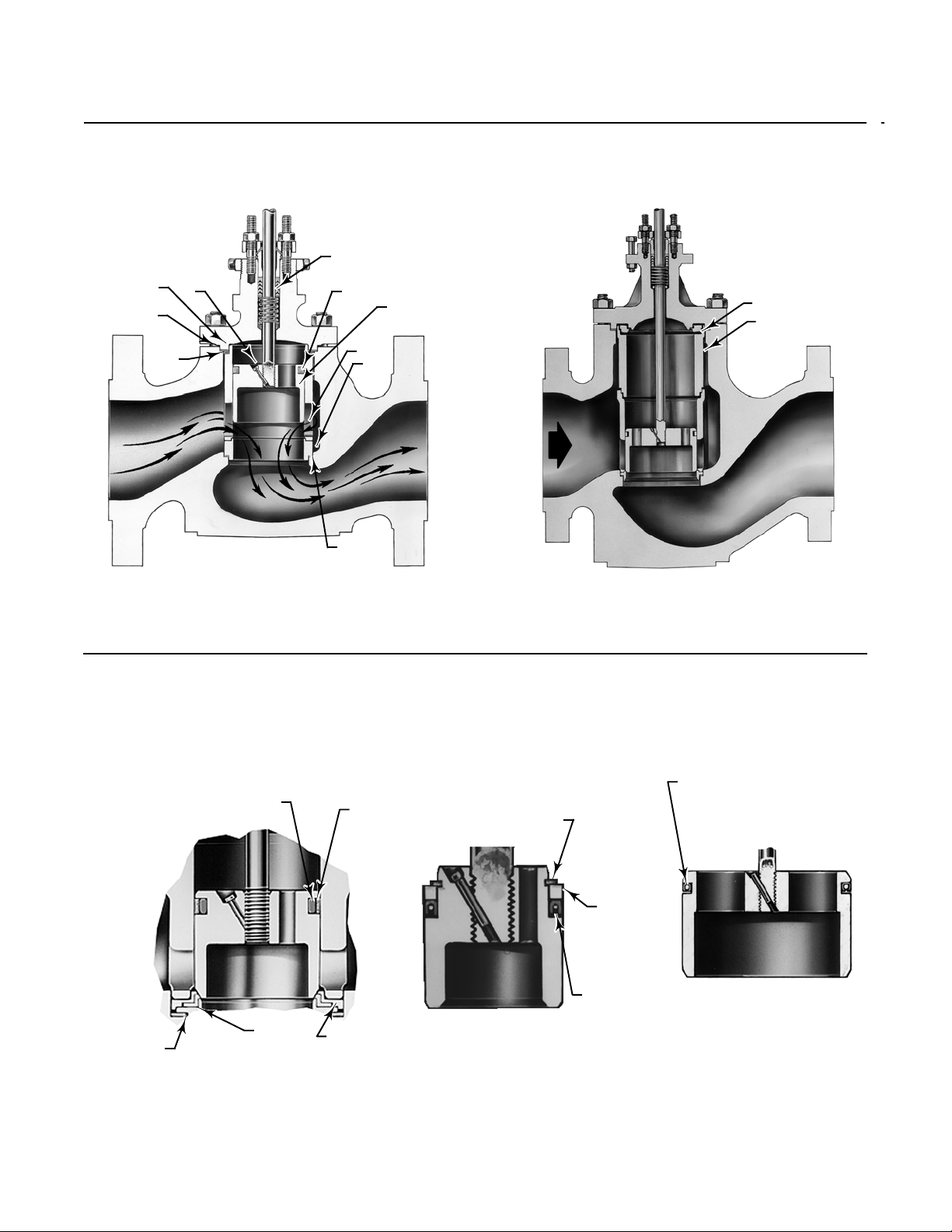
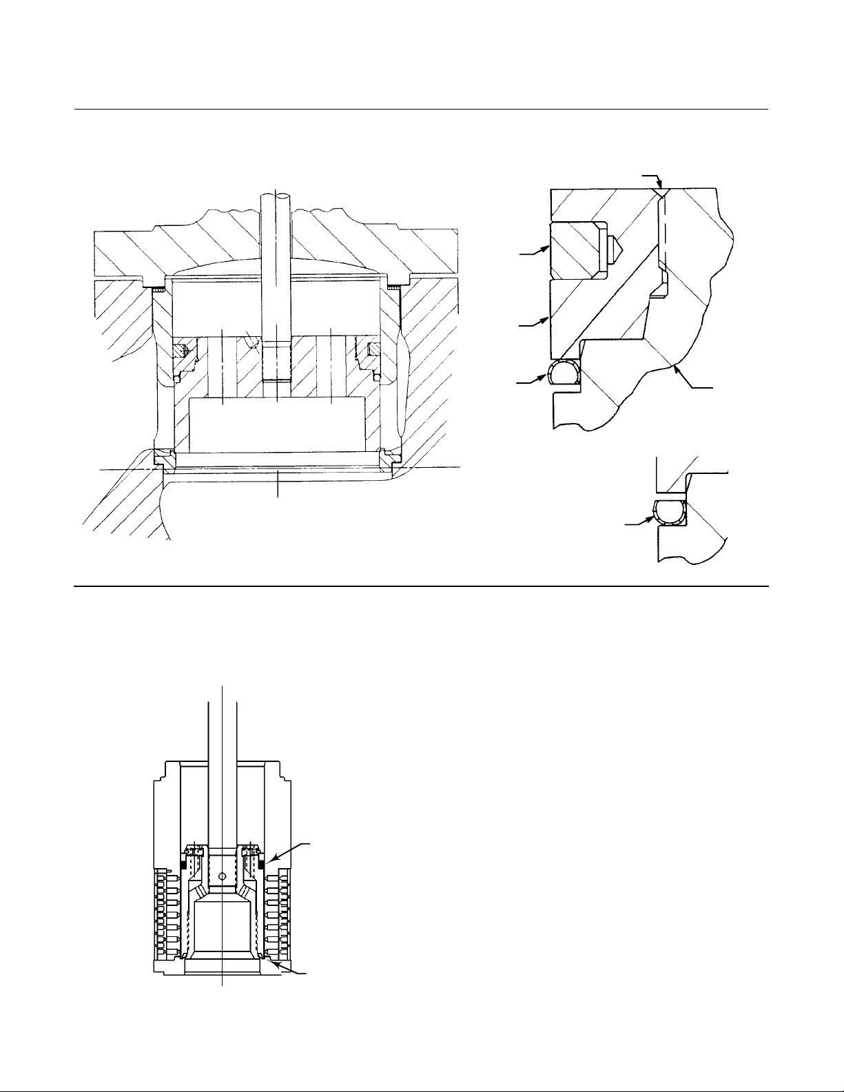
Figure 1. Fisher EWD Valve with Standard Cage
PTFE V-RING
BONNET
GASKET
SHIM
SPIRAL
WOUND
GASKET
PIN
PACKING
GRAPHITE PISTON
RING
CAGE
SEAT
RING
VALVE
PLUG
Product Bulletin
51.1:EW
August 2012
LOAD RING
CAGE
RETAINER
SEAT
RING
W9035
GASKET
TYPICAL OF CONSTRUCTIONS THROUGH NPS 12x6
NOTE:
THE NPS 10x8 VALVE IS SIMILARINAPPEARANCE TO SIZES THROUGH NPS 12x6. HOWEVER, THE NPS 10x8 USESTHELOADRINGSHOWN FOR THE NPS 12x8.
ITDOESNOTUSETHECAGERETAINER.
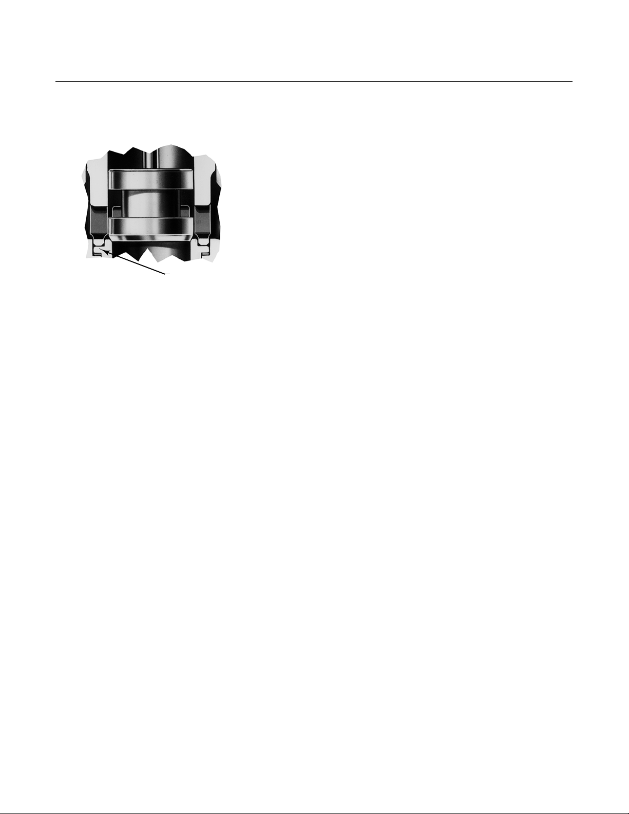
Figure 2. Fisher EWT Trim Details
SOFT BACKUP
RING
SEAL
RING
W9036
RETAINING
RING
NPS 12x8 CONSTRUCTION
SEAL RING
(SHOWN POSITIONED
FOR USE WITH
STANDARD AND
CAVITROL CAGES)
METAL
BACKUP
RING
W2914--1/ IL
178 mm (7 INCH)
AND LARGER PORTS
METAL
DISC SEAT
W0992-3
PTFE
DISC
METAL DISC
RETAINER
STANDARD CONSTRUCTION
(SEAT PARTS ALSO TYPICAL OF OPTIONAL
EWS PTFE SEATING
W0995-2
137 mm (5.375 INCH)
AND SMALLER PORTS
SEAL RING
(SHOWN POSITIONED
FOR USE WITH
STANDARD AND
CAVITROL CAGES)
VALVE PLUG WITH OPTIONAL
PRESSURE- ASSISTED SEAL RING
5
Page 6
Product Bulletin
51.1:EW
August 2012
EW Valve
D100023X012
Figure 3. Fisher EWS Trim Details Showing Standard
Cage and Seating Construction
W0989-2
CLAMPED METAL
SEAT RING
C-seal Trim Description
C-seal trim (figure 5) is available for valves with port
diameters from 2.875 inches through 8 inches.
With C-seal trim, a balanced valve can achieve
high-temperature, Class V shutoff. Because the C-seal
plug seal is formed from metal (N07718 nickel alloy)
rather than an elastomer, a valve equipped with the
C-seal trim can be applied in processes with a fluid
temperature of up to 593_C (1100_F).
ENVIRO-SEAL and
HIGH-SEAL Packing
Systems
Fisher ENVIRO-SEAL and HIGH-SEAL packing systems
(figure 18) offer excellent sealing capabilities. These
systems easily install in your existing valves or can be
purchased with new valves. These systems help you
seal your process to conserve valuable process fluid
and to protect the environment against the emission
of hazardous or polluting fluids. The long-life and
reliability of these systems also reduce your
maintenance cost and downtime.
For applications requiring compliance with
environmental protection regulations, the unique
ENVIRO-SEAL packing system and, for hazardous
service, the ENVIRO-SEAL bellows seal bonnet (figure
19) are offered. The emission control packing system
or seal bonnet keeps emission concentrations below
the EPA 100 ppm requirement.
For an excellent stem seal in applications that are not
environmentally-sensitive, the HIGH-SEAL Graphite
ULF packing system is offered. The HIGH-SEAL packing
system provides excellent sealing at
pressure/temperature ratings beyond ENVIRO-SEAL
limits.
ENVIRO-SEAL packing systems, available with PTFE,
Graphite ULF, or Duplex packing, and the HIGH-SEAL
Graphite ULF packing system feature live-loading and
unique packing-ring arrangements for long-term,
consistent sealing performance.
6
Page 7
EW Valve
D100023X012
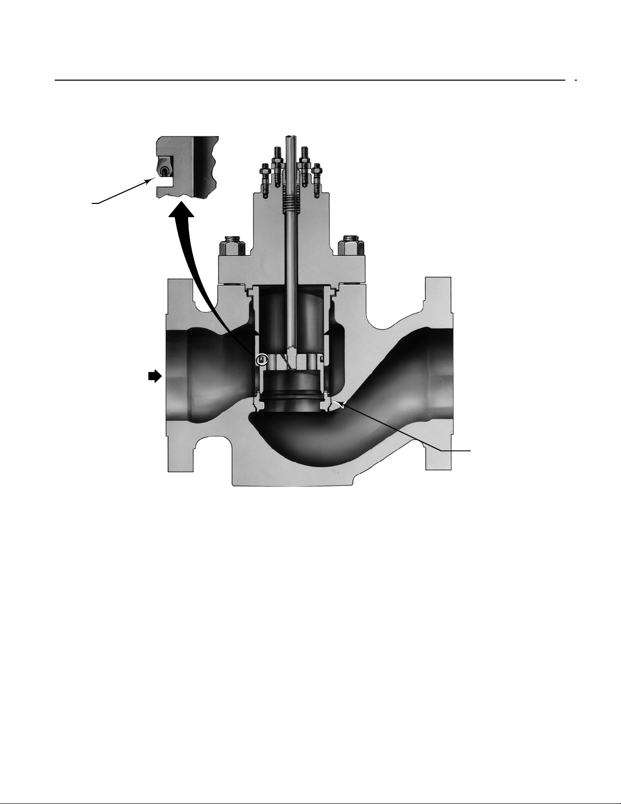
Figure 4. Fisher NPS 12x8 CL900 EWT-1 Valve
SEAL RING
(SHOWN
POSITIONED
FOR USE
WITH
STANDARD
CAGES)
Product Bulletin
51.1:EW
August 2012
W9037
THREADED
SEAT RING
7
Page 8
Product Bulletin
51.1:EW
August 2012
EW Valve
D100023X012
Figure 5. C-seal Trim
A6869
NOTES:
1. REVERSE THE ORIENTATION OF THE C-SEAL PLUG SEAL FOR PROPER S HUTOFF WHEN
VALVEISUSEDINAPROCESSWITHDIFFERENTFLUIDFLOWDIRECTION.
PISTON
RING
RETAINER
C-SEAL
METAL
PLUG
(1)
SEAL
STAKETHREAD
FLOW DOWN
C-SEAL
METAL
PLUG
(1)
SEAL
VALVE
PLUG
FLOW UP
Figure 6. Typical Balanced TSO Trim
A7096
8
VALVE PLUG
SEAL
PROTECTED SOFT SEAT
Page 9
Product Bulletin
EW Valve
D100023X012
Table 1. Metal Trim Part Materials for Compatibility with NACE MR0175-2002 (Sour Service) Specifications,
Environmental Restrictions Apply, Refer to Standard
Disk Seat and
Retainer for
Optional
PTFE-Seat
Construction
Valve Stem, Packing
Follower, Lantern Ring,
Packing Box Ring, and
Pin
S20910 (Valve Stem)
S31600 (All Other Parts)
Trim Designation Valve Plug Cage
85
(3)
S31600
S31600 with
electroless nickel
coating (ENC)
85C
(2,3)
S31600
S31600 with
electroless nickel
coating (ENC)
S31600 with seat
86
(3)
hard faced with
CoCr-A hardfacing
alloy
S31600 with seat
87
and guide hard
faced with CoCr-A
hardfacing alloy
S31600 with seat
87C
(2)
and guide hard
faced with CoCr-A
hardfacing alloy
1. NPS 10x8 and 12x8valve body only.
2. 85C and 87C aretrimsfor PTFE-seat constructions in EWS and EWT valves.
3. Not for usewith Whisper Trim Iwith5-3/8inchandlargerports.
S31600 with
electroless nickel
coating (ENC)
S31600 with
electroless nickel
coating (ENC)
S31600 with
electroless nickel
coating (ENC)
Seat Ring
for Standard
Metal Seat
Construction
S31600 ---
--- S31600
R30006 (alloy 6) ---
R30006 (alloy 6) ---
--- S31600
August 2012
51.1:EW
Load Ring
N05500
(1)
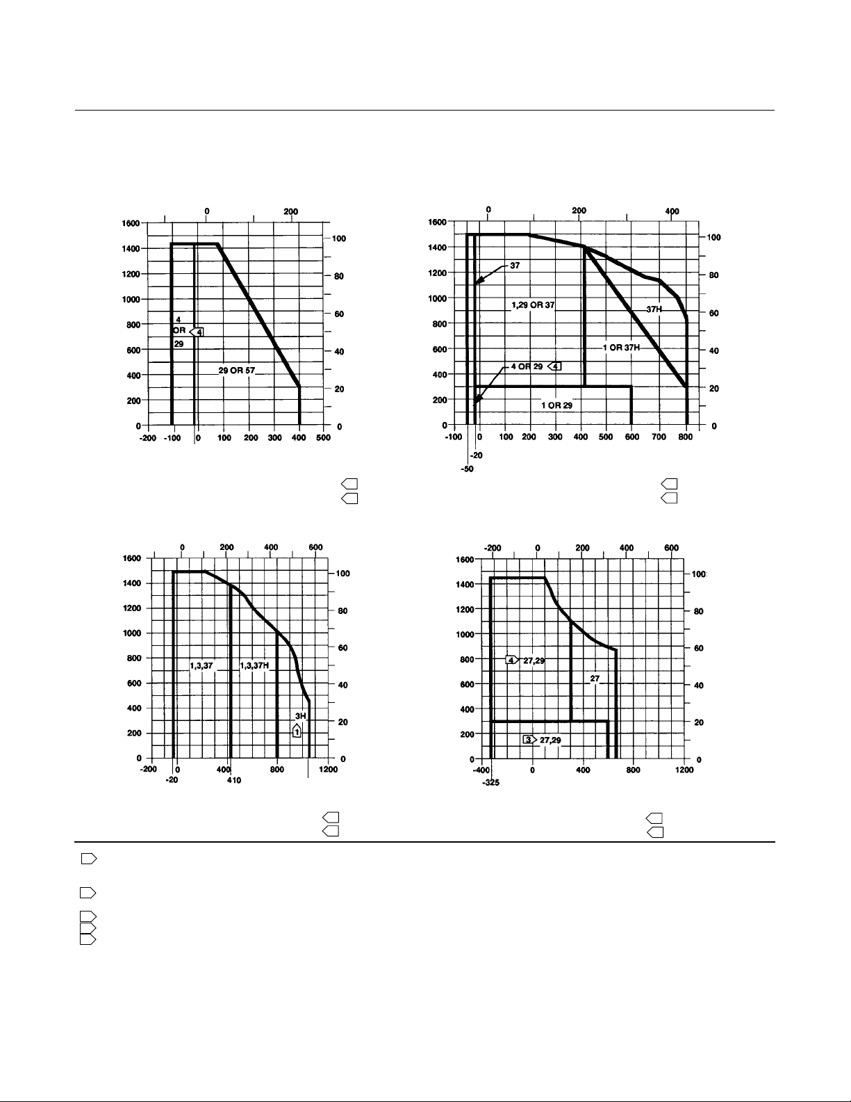
Figure 7. Typical Trim for NACE MR0175-2002 (Sour Service) (tables 11, 12, and 13 should be used along with these
graphs to determine specific limits based on valve size and trim selection)
FLUID TEMPERATURE, C
--100 --50 0 50 100 150 200 250
1600
1400
1200
1000
800
600
400
PRESSURE DROP, PSI
200
0
--200 --100
A3115-3
NOTES:
1
2
DO NOT EXCEED THE MAXIMUM PRESSURE AND TEMPERATURE FOR THE CLASS RATING OF THE BODY MATERIAL USED, EVEN THOUGH THE TRIMS SHOWN MAY
HAVE HIGHER CAPABILITIES.
3
USE TRIM 85 UP TO 99 BAR (1440 PSI) WITH CLEAN DRY GAS. FOR PROCESS FLUIDS OTHER THAN CLEAN DRY GAS, USE TRIM 85 ONLY UP TO 21 BAR (300 PSI).
4
TRIM 87 TEMPERATURE LIMIT CAN BE EXTENDED ABOVE 232C (450F) IF PEEK ANTI-EXTRUSION RINGS AND SPRING-LOADED SEAL RING ARE USED.
FOR STANDARD PTFE SEATING WITH ALL
USE TRIM 87 INSTEAD OF TRIM 85 FOR NONLUBRICATING FLUIDS SUCH AS SUPERHEATED STEAM OR DRY GASES BETWEEN 149C (300F) AND 316C(600F).
87C
85C
0 100 200 300 400 500
-- 5 0
FLUID TEMPERATURE, F
2
BODY MATERIALS
110
100
90
80
70
60
50
40
30
20
10
0
PRESSURE DROP, BAR
--100 --50 0 50 100 150 200 250
1600
1400
1200
1000
800
600
400
PRESSURE DROP, PSI
200
0
--200 --100 0 100 200 300 400 500 600
FOR OPTIONAL METAL SEATING WITH
FLUID TEMPERATURE, C
86
3
1
85
FLUID TEMPERATURE, F
2
CF8M MATERIAL
300
110
100
90
80
70
87
450
60
50
40
30
PRESSURE DROP, BAR
20
10
0
4
9
Page 10
Product Bulletin
51.1:EW
August 2012
EW Valve
D100023X012
---
---
---
(1)
CL150, 300, or 600 CL900
x
x
x
x
---
x
---
x
---
Table 2. Available Valve Constructions
VALVE
4x2 6x4 8x4 8x6 10x6
EWD
EWD-1
EWS
EWS-1
EWT
EWT-1
1. X indicates availableconstruction.
2. Two-number valve sizedesignatesend connection size x effective trim size.
3. NPS 10x6 has avalveoutlet area identical to the NPS 8x6.
---
---
---
x
x
x
x
---
x
---
x
---
Available Configurations
All configurations covered in this bulletin use a
single-port, globe-style valve body with cage guiding
and push-down-to-close valve plug action. This valve
style is combined with different plug styles and either a
clamped seat ring (no dash number suffix) or a seat
ring threaded into the valve body (-1 suffix).
EWD: Balanced valve plug (figure 1) with clamped seat
ring and metal-to-metal seating for all general
applications over a wide range of pressure drops and
temperatures.
EWD-1: NPS 12x8 CL900 EWD valve body, with
threaded seat ring.
EWS: Unbalanced valve plug (figure 3) with clamped
seat ring and metal-to-metal or optional metal-to-PTFE
seating for all general applications requiring better
shutoff capabilities than can be obtained with the EWD
valve body.
EWS-1: NPS 12x8 CL900 EWS valve body, with
threaded seat ring and metal-to-metal seating.
VALVE SIZE
---
---
---
(2)
,NPS
(3)
x
x
x
12x6 10x8 12x8 8x6 12x8
x
---
x
---
x
---
---
---
---
x
x
x
---
---
---
x
x
x
x
---
x
---
x
---
Material Selection
Guidelines
Regardless of valve construction, select the valve
body/bonnet material from the specifications table,
keeping in mind that the valve service conditions
cannot exceed the ASME pressure/temperature
limitations for the selected valve body. Then, perform
steps 1 and 2 under the appropriate valve design
heading to complete the selection process.
EWD, EWS, or EWT Valve With All
Except Cavitrol III or Whisper Trim III
Cages
1. Choose a trim combination for the service
conditions according to figure 7 and 8, while making
sure from tables 1 and 5 that this combination
provides the desired trim materials. Then, make sure
from table 11, 12, or 13 that the valve body/trim
temperature limits are not exceeded.
2. Finally, check in table 20 that packing and other
valve parts are available in materials that meet the
desired service conditions.
x
x
x
x
x
x
EWT: Balanced valve plug (figure 2) with metal- to-PTFE
seating (for stringent shutoff requirements) standard
in all EWT valves (except those with Cavitrol III cages).
Metal-to-metalseatingforhighertemperaturesis
standard for all EWT valve bodies with Cavitrol III cages
and optional for these valves with other cages.
EWT-1: NPS 12x8 CL900 EWT valve body, with
threaded seat ring and with metal-to-metal seating
(figure 4).
10
EWD-1, EWS-1, or EWT-1 Valve With
Standard Cage
1. Choose a trim combination for the service
conditions according to figure 9, while making sure
from table 7 that this combination provides the
desired trim materials.
2. Finally, check in table 20 that packing and other
valve parts are available in materials that meet the
desired service conditions.
Page 11

Product Bulletin
EW Valve
D100023X012
Table 3. Shutoff Classifications per ANSI/FCI 70-2 and IEC 60534-4
Valve Seating Shutoff Class
EWD or EWD-1 Metal
III (optional for NPS 6x4 through 12x8 valves)
IV (optional for NPS 6x4 through 12x8 valves with optional multiple graphite piston rings)
EWS or EWS-1 Metal
V (optional, consult your Emerson ProcessManagement sales office)
EWS PTFE VI
EWT with all except
Cavitrol III cages
EWT with
1-stage Cavitrol III cage
EWT with 2-stage Cavitrol III cage
or 2- or 3-stage Cavitrol III cage
EWT-1 Metal IV
1. Class V shutofffor EWT requires spring-loaded seal ring, radius-seat plug, and wide-bevel seat ring. Notavailable with 8-inch port, quick-opening cage. Not available withS31600 (316 SST)
valve plug and seatring(trims 4, 29, 85).
PTFE
Metal
Metal
Metal or PTFE V
Table 4. C-seal Shutoff Classification
Valve Valve Size, NPS Port Diameter, mm (Inches) Cage Style ANSI/FCI Leakage Class
6x4x2-1/2 73 (2.875) Eq. %, Linear, Whisper I, Cav III (2-stage)
6x4
8x4
8x6
EWD
(CL300, 600)
1. NPS 10x6 has avalveoutlet area identical to the NPS 8x6.
12x6
8x6
10x6
12x6
10x8
12x8
(1)
111.1 (4.375) Eq. %, Linear, Whisper I, Cav III (1-stage)
136.5 (5.375) Whisper III (A3, B3, D3, D3), Cav III (2-stage)
177.8 (7) Eq.%, Linear,Whisper I, Cav III (1-stage)
203.2 (8) Eq.%, Linear,Whisper I, Cav III (1-stage)
II (standard)
IV (standard)
V (optional)
IV
(1)
V
IV (standard)
V (optional)
V to 593_C (1100_F)
diameters from
73 through 203.2 mm
(2.875 through 8-inch) with
optional C-seal trim)
51.1:EW
August 2012
(for port
EWT Valve With Cavitrol III Cage
1. Choose a trim combination for the service
conditions according to figure 12, while making sure
from table 15 that this combination provides the
desired trim materials. Then, make sure from table 16
that the valve body/trim temperature limits are not
exceeded.
2. Finally, check in table 20 that packing and other
valve parts are available in materials that meet the
desired service conditions.
EWD, EWS, or EWT Valve With
Whisper Trim III Cage
1. Choose a trim combination for the service
conditions according to figure 15, while making sure
from table 17 that this combination provides the
desired trim materials. Then, make sure from
table18thatthevalvebody/trimtemperaturelimits
are not exceeded.
2. Finally, check in table 20 that packing and other
valve parts are available in materials that meet the
desired service conditions.
EWD-1, or EWT-1 Valve With
Whisper Trim III Cage
1. Choose a trim combination for the service
conditions according to figure 16 or 17, while making
sure from table 19 that this combination provides the
desired trim materials.
2. Finally, check in table 20 that packing and other
valve parts are available in materials that meet the
desired service conditions.
11
Page 12

Product Bulletin
51.1:EW
August 2012
EW Valve
D100023X012
Table 5. Fisher EWD, EWS, and EWT Metal Trim Part Combinations
(1)
Trim III Cages
TRIM DESIGNATIONS VALVE PLUG CAGE
1 (standard trim for all valves except
EWT and those in CF8M. Trim 57 is
standard for EWT. Trim 29 is standard
for all valves in CF8M)
(2)
3and3H
(6)
4
27 S31600 w/seat and
(6)
29
(standard for all valves
in CF8M)
37 and 37H
57 (standard for all EWT valve bodies
in all materials except CF8M)
1. Nonferrous alloy combinations arealsoavailable. Consult your Emerson Process Management sales office fordetails.
2. Trims 3H and37Hhave clearances for high-temperature service.
3. Available only inlinear, quick-opening, equal percentage, and Whisper Trim I cages.
4. Solid cast alloy 6seatring is used instead for NPS 4x2, 10x8, and12x8 valve sizes.
5. CA15 is used forNPS8x6 CL900 EWD and EWS.
6. Not for usewith Whisper Trim Iwith5-3/8inchandlargerports.
(2)
S41600 heat treated CB7CU-1 (S17400)
S31600 w/seat and
guide hard faced
w/CoCr-A
hardfacing alloy
S31600 CB7CU-1(S17400)
guide hard faced
w/CoCr-A
hardfacing alloy
S31600 CF8M w/electroless
S31600 w/seat and
guide hard faced
w/CoCr-A
hardfacing alloy
S41600 heat treated CB7CU-1 (S17400)
heat treated
R30006 (alloy 6)
heat treated
CF8M w/electroless
nickel coating
(ENC)
nickel coating (ENC)
CB7CU-1 (S17400)
heat treated
heat treated
Disk Seat, Retainer for PTFE
(3)
S31600 w/seat hard faced
w/CoCr-A hardfacing alloy
S31600 w/seat hard faced
w/CoCr-A hardfacing alloy
S31600 w/seat hard faced
w/CoCr-A hardfacing alloy
Except for Valves with Cavitrol III or Whisper
SEAT
Seat Constructions
---
Seat Ring for Metal Seat
Constructions
J S41600 or CA15
EWD, EWS
(5)
(S41000) for
J CA6NM for EWD-1,
EWS-1, EWT-1
(4)
S31600 S31600
(4)
S31600 S31600
(4)
S31600 ---
S31600
w/seat hard faced w/CoCr-A
hardfacing alloy
S31600 w/seat hard faced
w/CoCr-A hardfacing alloy
S31600 w/seat hard faced
w/CoCr-A hardfacing alloy
(4)
(4)
(4)
ANSI/FCI Class VI Shutoff Capabilities
EWS valves with metal seat constructions and EWT valves with soft seat and metal seat constructions can provide
ANSI/FCI Class VI shutoff capabilities. See tables 6 and 7.
Table 6. Class VI Shutoff Availability
Valve Port Size, Inches Seat Minimum Seat Load
EWS
EWT
EWT
± 7
² 3.4375 ± 7
² 3.4375 ± 7
Table 7. Class VI Trim Materials
VALVE CAGE VALVE PLUG SEAT RING SEAL RING
EWS
EWT
1. UHMWPE (Ultra High Molecular WeightPolyethylene)
S31600 (316 SST)
/ENC
S31600 / ENC S31600 S31600/PTFE UHMWPE
S31600 / ENC S31600/CoCr-Aseat S31600 UHMWPE R30003 -101 to 66 -150 to 150
S17400 (17-4PH SST) S41600 S31600/PTFE UHMWPE R30003 -29 to 66 -20 to 150
S17400 S41600 S31600 UHMWPE R30003 -29 to 66 -20 to 150
12
S31600/CoCr-A
(alloy 6) seat
S31600 NA Not a limiting factor
Metal 300 lbs/lineal inch
Soft See Catalog 14
Metal 300 lbs/lineal inch
TRIM TEMPERATURE LIMIT
_C _F
(1)
R30003 -29 to 66 -20 to 150
Page 13

Product Bulletin
EW Valve
D100023X012
51.1:EW
August 2012
Fisher TSO (Tight Shutoff) Trim Capabilities
See figure 6 and tables 8, 9, and 10. For additional information contact your Emerson Process Management sales
office.
Table 8. TSO (Tight Shutoff) Leakage Class
Leakage Class Maximum Leakage Test Medium Test Pressure Test Procedure
Valves with TSO trim are factory
TSO (Tight Shutoff)
1. Specify service Pwhenordering.
tested to a more stringent Fisher test
requirement of no leakage at time of
shipment.
Water Service P
Table 9. TSO Shutoff Availability
VALVE CONSTRUCTION
EWT Std or Cavitrol III trim. Replaceable, protected soft seat
(1)
ANSI/FCI Class V test procedure B
Table 10. Port Diameters, Valve Plug Travel, Yoke Boss Diameters for TSO (Tight Shutoff) Trim
MAX
VALVE TRIM
EWT NPS 6x4 Std 50.8 2 90 3-9/16 111 4.375 106 4.1875
EWT NPS 8x6
1. This column lists the percent reduction of published maximum CVof the trim listedin the TRIM column.
2. NPS 10x6 has avalveoutlet area identical to the NPS 8x6.
and 10x6
(2)
TRAVEL
mm Inch mm Inch
50.8 2
Std
102 4 90 3-9/16 2%
YOKE BOSS SIZE PORT DIAMETER
Nominal Actual TSO
mm Inch mm Inch Inch
90
127
3-9/16
5
179 7 173 6.8125
CVREDUCTION AT 100%
TRAVEL
4% (linear)
3% (equal percent)
Installation
Unless limited by seismic criteria, the valve body can
be installed in any position (as long as sufficient
support is provided if a fabricated extension bonnet is
used). However, the normal method is with the
actuator vertical above the valve, since nonvertical
positionsmaycauseuneventrimwearanddecreased
trim life.
Flow through the valve body must be in the direction
indicated by the flow direction arrow on the valve
body. Consider installing an upstream strainer,
especially if the valve body includes slotted or
multihole Whisper Trim or Cavitrol cages.
Dimensions are shown in figure 20.
2%
UNBALANCE
(1)
AREA
2
0.154
0.30
13
Page 14
Product Bulletin
51.1:EW
August 2012
Figure 8. Typ ical Trim U sed in Fisher EWD, EWS, or EWT Valves Except Those with Cavitrol III or Whisper Trim III Cages
(tables 11, 12, and 13 should be used along with these graphs to determine specific limits based on valve size and
trim selection)
FLUID TEMPERATURE, C
FLUID TEMPERATURE, C
EW Valve
D100023X012
PRESSURE DROP, PSI
PRESSURE DROP, PSI
-20
FLUID TEMPERATURE, F
FOR PTFE SEATING WITH ALL CL600
OR NPS 12x8 CL900 BODY MATERIALS
FLUID TEMPERATURE, C
PRESSURE DROP, BAR
5 5
2
PRESSURE DROP, BAR
PRESSURE DROP, PSI
FLUID TEMPERATURE, F
WITH CL600 OR NPS 12x8 CL900
WCC OR LCC STEEL BODY
FLUID TEMPERATURE, C
PRESSURE DROP, PSI
PRESSURE DROP, BAR
2
PRESSURE DROP, BAR
1050
FLUID TEMPERATURE, F
A6334-1
NOTES:
1
BE ESPECIALLYCAREFULTO SPECIFY SERVICE TEMPERATURE IFTRIM3,4, OR 37 IS SELECTED,ASDIFFERENTTHERMAL EXPANSION RATES REQUIRE SPECIAL PLUG
CLEARANCES, ALSO, USE TRIM 37H INSTEAD OF TRIM 4 FOR NON-LUBRICATING FLUIDS SUCH AS SUPERHEATED STEAM OR DRY GASES BETWEEN 149C (300F) AND
316C(600F).
2
DO NOTEXCEEDTHE MAXIMUM PRESSURE AND TEMPERATUREFORTHE CLASS RATING OF THEBODYMATERIAL USED, EVEN THOUGH THETRIMSSHOWN MAY
HAVE HIGHER CAPABILITIES.
3
USE TRIM 27 INSTEAD OF TRIM 29 FOR NON-LUBRICATING FLUIDS SUCH AS SUPERHEATED STEAMOR DRY GASES BETWEEN149C (300F) AND 316C(600F).
4
TRIMS 4 AND 29 MAY BE USED OVER 300 PSI ONLY WITH CLEAN, DRY GAS.
5
EWD, EWS, AND EWT NPS 12x8 CL900 LIMITED TO CL600 PRESSURE DROPS. SEE FIGURE 9 AND 10 EWD-1, EWS-1, AND EWT-1 FOR FULL CL900 NPS 12x8
PRESSURE DROPS.
WC9 CHROME MOLY STEEL BODY
WITH CL600 OR NPS 12x8 CL900
5
2
WITH CL600 OR NPS 12x8 CL900
FLUID TEMPERATURE, F
CF8M (316SST) BODY
5
2
14
Page 15

EW Valve
D100023X012
Product Bulletin
51.1:EW
August 2012
Table 11. Valve/Trim Temperature Capabilities
(1)
for CL300 or 600 Fisher EWD, EWS, and EWT Valves with 2-Inch (51
mm) or 3-Inch (76 mm) Travel (Except those with Cavitrol III or Whisper Trim III Cages) (figures 7 and 8 should be
used along with this table to determine specific limits based on valve size and trim selection)
VALVE/BONNET
MATERIAL
WCC steel
LCC steel
WC9 chrome moly steel
CF8M (316 SST)
1. For metal trimpartsonly.
2. May be used down to -254_C (-425_F) if manufacturing process includes Charpy Impacttest.
3. NPS 10x6 has avalveoutlet area identical to the NPS 8x6.
TRIM DESIGNATION
FROM TABLE 5
1
29, 85
37 4x2through12x8 -29 210 -20 410
37H 4x2through12x8 210 427 410 800
57 4x2through12x8 -29 204 -20 400
1
57 4x2through10x8 -29 204 -20 400
29, 85
37 4x2through12x8 -46 210 -50 410
37H 4x2through12x8 210 343 410 650
1
3 4x2through12x8 -29 427 -20 800
3H 4x2through12x8 427 566 800 1050
27, 87
29, 85
37 4x2through12x8 -29 210 -20 410
37H 4x2through12x8 210 427 410 800
57 4x2through12x8 -29 204 -20 400
27 4x2through12x8 -198
29, 85 4x2through12x8 -198
8x6or10x6
12x8or10x8
8x6or10x6
12x8or10x8
8x6or10x6
10x8or12x8
8x6or10x6
10x8or12x8
8x6or10x6
12x8or10x8
8x6or10x6
12x8or10x8
8x6or10x6
12x8or10x8
VALVE SIZE,
NPS
4x2
6x4
8x4
12 x 6
4x2
6x4
8x4
12 x 6
4x2
6x4
8x4
12 x 6
4x2
6x4
8x4
12 x 6
4x2
6x4
8x4
12 x 6
4x2
6x4
8x4
12 x 6
4x2
6x4
8x4
12 x 6
(3)
(3)
(3)
(3)
(3)
(3)
(3)
MATERIAL TEMPERATURE CAPABILITY
_CMin _CMax _FMin _FMax
-29
-29
-29
-29
-29
-29
-29
-29
-29
-29
-29
-29
-29
-29
-29
-29
-29
-29
-46
-46
-46
-46
-46
-46
-29
-29
-29
-29
-29
-29
-29
-29
-29
-29
-29
-29
-29
-29
-29
-29
-29
-29
(2)
(2)
399
343
329
316
260
427
316
221
218
204
174
316
343
343
329
329
260
343
316
218
218
204
163
316
399
343
329
316
260
427
343
221
218
204
163
343
316
221
218
204
163
316
343 -325
316 -325
-20
-20
-20
-20
-20
-20
-20
-20
-20
-20
-20
-20
-20
-20
-20
-20
-20
-20
-50
-50
-50
-50
-50
-50
-20
-20
-20
-20
-20
-20
-20
-20
-20
-20
-20
-20
-20
-20
-20
-20
-20
-20
750
650
625
600
500
800
600
430
425
400
345
600
650
650
625
625
500
650
600
425
425
400
325
600
750
650
625
600
500
800
650
430
425
400
325
650
600
430
425
400
325
600
(2)
(2)
650
600
15
Page 16

Product Bulletin
51.1:EW
August 2012
EW Valve
D100023X012
Table 12. 4-Inch (102 mm) Travel Whisper Trim I Fisher EWD and EWT Valve Body/Trim Temperature Capabilities
(1)
(CL150 - 600 and NPS 8 x 6, CL900) (figure 8 should be used along with this table to determine specific limits based
on valve size and trim selection)
MATERIAL TEMPERATURE
BODY/BONNET
MATERIAL
(2)
TRIM DESIGNATION
FROM TABLE 5
VALVE SIZE, NPS
_C _F
CAPABILITY
Min Max Min Max
8x6or10x6
8x6or10x6
WCC steel
37H
LCC steel
WC9 chrome moly steel
1. For metal trimpartsonly.
2. Same material also usedforbonnet spacer.
3. NPS 10x6 has avalveoutlet area identical to the NPS 8x6.
4, 57 8x6or10x6
37H 8x6or10x6
1
3 8x6or10x6
57 8x6or10x6
37 8x6or10x6
1 8x6or10x6
37 8x6or10x6
3 8x6or12x6 -29 427 -20 800
3H 8x6or12x6 427 566 800 1050
Table 13. Fisher CL900 EWD, EWS, and EWT Valve Body/Trim Temperature Capabilities
(3)
12 x 6
(3)
or 12 x 6 -29 427 -20 800
(3)
or 12 x 6 -29 204 -20 400
(3)
or 12 x 6 -29 210 -20 410
(3)
12 x 6
(3)
(3)
(3)
(3)
-29
-29
210
210
-29 329 -20 625
-46 204 -50 400
-29 210 -20 410
210 343 410 650
329
285
427
363
(1)
(figure 8 should be used
-20
-20
410
410
625
545
800
685
along with this table to determine specific limits based on valve size and trim selection)
MATERIAL TEMPERATURE
BODY/BONNET
MATERIAL
WCC steel
LCC steel
WC9 chrome moly steel
316 SST (CF8M)
1. For metal trimpartsonly.
2. May be used down to -254_C (-425_F) if manufacturing process includes Charpy impacttest.
TRIM DESIGNATION
FROM TABLE 5
1
29, 85
37 8x6or12x8 -29 210 -20 410
37H 8x6or12x8 210 427 410 800
57 8x6or12x8 -29 204 -20 400
1 8x6only -29 329 -20 625
4, 37 8x6only -46 210 -50 410
37H 8x6only 210 371 410 700
57 8x6only -29 204 -20 400
29, 85 8x6only -46 204 -50 400
1
3 8x6 -29 427 -20 800
3H 8x6 427 566 800 1050
3 12 x 8 -29 427 -20 800
3H 12 x 8 427 566 800 1050
27, 87
29, 85
37 8x6or12x8 -29 210 -20 410
37H 8x6or12x8 210 427 410 800
57 8x6or12x8 -29 204 -20 400
27, 87 8x6or12x8 -198
29, 85 8x6or12x8 -198
VALVE
SIZE, NPS
8x6
12 x 8
8x6
12 x 8
8x6
12 x 8
8x6
12 x 8
8x6
12 x 8
_C _F
Min Max Min Max
-29
-29
-29
-29
-29
-29
-29
-29
-29
-29
(2)
(2)
CAPABILITY
316
427
204
316
316
427
204
343
204
316
343 -325
316 -325
-20
-20
-20
-20
-20
-20
-20
-20
-20
-20
600
800
400
600
600
800
400
650
400
600
(2)
(2)
650
600
16
Page 17

Product Bulletin
EW Valve
D100023X012
Figure 9. Typical Trim Used in Fisher EWD, EWS, and EWT NPS 8x6 CL900 Valves with Standard Cages and EWD-1,
EWS-1, and EWT-1 NPS 12x8 CL900 Valves with Standard Cages (see table 14)
FLUID TEMPERATURE, C FLUID TEMPERATURE, C
51.1:EW
August 2012
PRESSURE DROP, PSI
A6334-1
NOTE:
1
DONOTEXCEEDTHEMAXIMUMPRESSUREANDTEMPERATUREFORTHECLASSRATINGOFTHEBODYMATERIALUSED,EVENTHOUGHTHE
TRIMS SHOWN MAY HAVE HIGHER CAPABILITIES.
FLUID TEMPERATURE, F
WITH WCC STEEL BODY
1
PRESSURE DROP, BAR
PRESSURE DROP, PSI
FLUID TEMPERATURE, F
WITH WC9 CHROME MOLY STEEL BODY
Figure 10. Typical Trim Used in NPS 8x6 CL900 Fisher
EWD, EWS, EWT and NPS 12x8 CL900 EWD-1,
EWS-1, and EWT-1 Valves with Standard Cages (see
table 14)
PRESSURE DROP, PSI
FLUID TEMPERATURE, C
PRESSURE DROP, BAR
Table 14. NPS 8x6 CL900 Fisher EWD, EWS, EWT
and NPS 12x8 CL900 EWD-1, EWS-1, and EWT-1
Metal T rim Part Combinations Except for Valves with
Whisper Trim III Cages
Trim
Designation
1
27
37 and 37H
1. CA6NM is similar to 410 SST.
2. Trim 37H has clearancesfor high-temperature service.
Valve Plug Cage Seat Ring
S41600
heat
treated
hard-faced
with CoCr-A
S31600 with
hard-faced
with CoCr-A
(2)
(416 SST)
316 SST with
seat and guide
seat and guide
CB7CU-1
(17-4PH SST)
with H900
heat-treat
condition
316 SST with
electroless
nickel coating
(ENC)
CB7CU-1with
H900
heat-treat
condition
PRESSURE DROP, BAR
1
Heat-treated
CA6NM
316 SST with
seat
hard-faced
with CoCr-A
S31600 with
seat
hard-faced
with CoCr-A
(1)
A6334-1
NOTE:
1
FOR THECLASS RATING OFTHE BODY MATERIALUSED, EVEN THOUGHTHE
TRIMS SHOWN MAY HAVE HIGHER CAPABILITIES.
DO NOT EXCEED THE MAXIMUM PRESSURE AND TEMPERATURE
FLUID TEMPERATURE, F
WITH CF8M (316 SST) BODY
1
17
Page 18

Product Bulletin
51.1:EW
August 2012
EW Valve
D100023X012
Figure 11. Detail of 2-Stage Cavitrol III Cage in CL300
or 600 Fisher EWT Valve
CAGE
RETAINER/
BONNET
SPACER
W3331-1
Table 15. Cavitrol III
Trim
Designation
76 Heat-treated S42000 (420 SST)
1. Available only inE WT valve.
2. Not used inNPS 12x8 or 8x6 CL900 valves.
(1)
Metal Trim Part Combination
Valve Plug Cage Cage Retainer
Figure 12. Typical Trim Used in Cavitrol III Cage
Constructions with Steel or Stainless Steel Valves
(see tables 15)
PRESSURE DROP, PSI
A2732
NOTE:
DO NOT EXCEED THE MAXIMUM PRESSURE AND TEMPERATURE FOR THE
CLASS RATING OF THE BODY MATERIAL USED, EVEN THOUGH THE TRIMS
SHOWN MAY HAVE HIGHER CAPABILITIES.
S17400 (17-4PH SST) with
H900 heat-treat condition
LIQUID TEMPERATURE, C
LIQUID TEMPERATURE, F
(2)
S31600 (316 SST)
PRESSURE DROP, BAR
Seat Ring
S17400 with H900
heat-treat condition
Table 16. Cavitrol III Valve Body/Trim Temperature Capabilities
TRIM
DESIGNATION
FROM TABLE 15
76
S31600 (316 SST)
1. NPS 10x6 has avalveoutlet area identical to the NPS 8x6.
2. This valve body/trimcombination not available in CL900 valve.
3. This valve body/trimcombination available in all NPS 12x8 ratingclasses.
18
VALVE BODY and BONNET
Min Max Min Max
WCC carbon steel or WC9 chrome moly steel -29
LCC carbon steel -46 -50
NPS 4x2 valve
NPS 6x4 valve
NPS 8x4 valve
NPS 8x6 or 10x6
NPS 12x6 valve
NPS 12x8 valve
(1)
(2)
valve
(3)
-29
-29
-29
-29
-29
-29
MATERIAL TEMPERATURE
CAPABILITY
_C _F
These materials not
limiting factors
204
149
135
121
107
177
-20
-20
-20
-20
-20
-20
-20
These materials not
limiting factors
400
300
275
250
225
350
Page 19

EW Valve
D100023X012
Product Bulletin
51.1:EW
August 2012
Figure 13. Fisher EWT Metal-Seat Valve with Whisper
Trim I Cage
BACKUP
RING
Figure 14. NPS 8x6 Fisher EWD Valve with Whisper
Trim III Cage (shown with optional drain plug)
OPTIONAL TRIPLE PISTON
RINGS USED TO OBTAIN
CLASS IV SHUTOFF (THIS
OPTIONAL SHUTOFF ALSO
AVAILABLE IN OTHER
EWD SIZES AND
CONSTRUCTIONS)
SEAL RING
CAGE
W9038
W9039
Figure 15. Typical Trim Used in Fisher EWD, EWS, and EWT Valves with Whisper Trim III Cages (see table 17)
FLUID TEMPERATURE, C
FLUID TEMPERATURE, C
CAGE
RETAINER
BONNET
SPACER
BAFFLE
317
301,
317,
PRESSURE DROP, PSI
A6334
NOTE:
1
DO NOT EXCEEDTHEMAXIMUM PRESSURE AND TEMPERATUREFOR THE CLASS RATING OF THE BODY MATERIAL U SED, EVEN THOUGH THE TRIMS SHOWN MAY
HAVE HIGHER CAPABILITIES.
318
FLUID TEMPERATURE, F
WITH CL600 WCC STEEL OR
WC9 CHROME MOLYVALVE
PRESSURE DROP, BAR
1050
1 1
PRESSURE DROP, PSI
FLUID TEMPERATURE, F
WITH CL600
CF8M (316SST) VALVE
PRESSURE DROP, BAR
19
Page 20

Product Bulletin
51.1:EW
August 2012
EW Valve
D100023X012
Table 17. Metal Trim Part Combinations for Fisher EWD, EWS, and EWT Valves with Whisper Trim III Cages
Trim
Designation
301 (standard for
all valve materials
except CF8M [316 SST])
(5)
301C
304
312 (for level D NACE)
313 (NACE compatible)
313C (NACE
compatible)
(4)
315
317
(4)
318
1. For NPS 8x6, 10x6,or12x6 valves only. (NPS 10x6 has a valve outletareaidentical to the NPS 8x6.)
2. Level D1 andD3cages cannot be certified to NACE. Use 316/ENCcageretainer instead (trim 312).
3. Unless otherwisenoted, all NACE references are to NACE MR0175-2002.
4. Not available for EWT constructions.
5. Available forEWTconstructions only.
(2)
(2, 5)
Valve Plug Cage
S17400 (17-4PH SST)
heat treated
S17400 (17-4PH SST)
heat treated
S31600 with seat and
guide hard-faced with
CoCr-A (Alloy 6)
S31600 with seat and
guide hard-faced with
CoCr-A
S31600 with seat and
guide hard-faced with
CoCr-A
S31600 with seat and
guide hard-faced with
CoCr-A
S31600 with seat and
guide hard-faced with
CoCr-A
S31600 with seat and
guide hard-faced with
CoCr-A
S31600 with seat and
guide hard-faced with
CoCr-A
S41600 (416 SST)
heat treated
S41600 (416 SST)
heat treated
S41600 heat
treated
S31600 with
electroless nickel
coating (ENC)
S31600 with
electroless nickel
coating (ENC)
S31600 with
electroless nickel
coating (ENC)
S31600 Cr Ct S31600 Cr Ct S31600 ---
WC9/Nitride WC9/Nitride Steel --- S41600
WC9/Nitride WC9/Nitride WC9 ---
Cage
Retainer
WCC/A105
(3)
with ENC)
(NACE
WCC/A105
(NACE with ENC)
WCC/A105
(NACE with ENC)
S31600 with
electroless nickel
coating (ENC)
WCC/A105
(NACE with ENC)
WCC/A105
(NACE with ENC)
Baffle
(for Level
D3 Cage
Only)
Steel ---
Steel
Steel ---
S31600 ---
Steel ---
Steel S31600 ---
Disk Seat and
Retainer for
PTFE-Seat
Construction
S41600 (416 SST)
S31600
(316 SST)
S31600 with seat
S31600 with seat
S31600 with seat
S31600 with seat
S31600 with seat
(1, 3)
Seat Ring
for Metal-Seat
Construction
heat treated
---
hard-faced with
CoCr-A
hard-faced with
CoCr-A
hard-faced with
CoCr-A
hard-faced with
CoCr-A
hard-faced with
CoCr-A
20
Page 21

EW Valve
D100023X012
Product Bulletin
51.1:EW
August 2012
Table 18. Valve/Trim Temperature Capabilities for Fisher EWD, EWS, and EWT Valves with Whisper Trim III Cages
VALVE/BONNET/
BONNET SPACER
MATERIAL
WCC steel or WC9
chrome moly steel
CF8M (316 SST)
1. May be used upto538_C (1000_F) if manufacturing processcontrols carbon content to 0.04% minimum or 0.08% maximum.
2. Unless otherwisenoted, all NACE references are to NACE MR0175-2002.
3. NPS 10x6 has avalveoutlet area identical to the NPS 8x6.
TRIM DESIGNATION
FROM TABLE 17
301
301C (for soft seats) 8 x 6, 10 x 6
304
312
313 (NACE
313C (NACE
(2)
compatible)
(2)
compatible)
(for soft seats)
315
318 (WCC only) 8 x 6, 10 x 6
318(WC9only) 8 x 6, 10 x 6
301, 301C (for soft
seats), 304
312
313 (NACE
313C (NACE
(2)
compatible) 8 x 6, 10 x 6
(2)
compatible)
(for soft seats)
8 x 6, 10 x 6
315 8x 6, 10 x 6
VALVE SIZE,
NPS
8x6or 10 x 6
12 x 6
(3)
,or12x6 -29 204 -20 400
8x6or 10 x 6
12 x 6
8x6or 10 x 6
12 x 6
8x6or 10 x 6
12 x 6
8x6or 10 x 6
12 x 6
8x6or 10 x 6
12 x 6
(3)
,or12x6 -29 427 -20 800
(3)
,or12x6 -29 593 -20 1100
8x6or 10 x 6
12 x 6
8x6or 10 x 6
12 x 6
(3)
,or12x6 -29 316 -20 600
(3)
,or12x6 -29 204 -20 400
(3)
,or12x6 -198 427
(3)
(3)
(3)
(3)
(3)
(3)
(3)
(3)
MATERIAL TEMPERATURE CAPABILITY
_C _F
Min Max Min Max
-29
-29
-29
-29
-29
-29
-29
-29
-29
-29
-29
-29
-29
-29
338
313
343
338
204
177
232
204
204
204
204
177
149
121
-20
-20
-20
-20
-20
-20
-20
-20
-20
-20
-20
-20
-20
-20
640
595
650
640
400
350
450
400
400
400
400
350
300
250
not a limiting factor
(1)
-325 800
(2)
(1)
21
Page 22

Product Bulletin
51.1:EW
August 2012
Figure 16. Typical Trim Used in Fisher EWD-1 Valves with Whisper Trim III Cages (see table 19)
FLUID TEMPERATURE, C
I, II
FLUID TEMPERATURE, C
EW Valve
D100023X012
PRESSURE DROP, PSI
PRESSURE DROP, BAR
FLUID TEMPERATURE, F
B1484-1
NOTE:
1
HAVE HIGHER CAPABILITIES.
2
WITH STEEL OR CHROME MOLY STEEL VALVE
DO NOT EXCEEDTHEMAXIMUM PRESSURE AND TEMPERATUREFOR THE CLASS RATING OF THE BODY MATERIAL U SED, EVEN THOUGH THE TRIMS SHOWN MAY
MAY BE USED DOWN TO -101C (-150F) WITH LEVEL A, B, OR C CAGE, OR WITH LEVEL D CAGE THAT HAS AN 18-8 SST BAFFLE.
PRESSURE DROP, PSI
WITH CF8M (316 SST) VALVE
IV
FLUID TEMPERATURE, F
11
Table 19. Fisher EWD-1andEWT-1 Metal Trim Part Combinations for Valves with Whisper Trim III Cages
Trim Designation Valve Plug Cage Seat Ring
I Heat-treated CA6NM
II
IV
1. CA6NM is similar to410 SST.
(1)
S31600 (316 SST) with seat and
guide hard faced withCoCr-A
CF8M (316 SST) with seat and
guide hard faced with
CoCr-A
CB7CU-1(17-4PH SST) with
H1025 heat-treat condition
CB7CU-1 with H1025
heat-treat condition
CB7CU-1 with H0125
heat-treat condition
Heat-treated CA6NM
N06600 with seat
hard faced with CoCr-A
CF8M with seat
hard faced with CoCr-A
PRESSURE DROP, BAR
22
Page 23

EW Valve
D100023X012
Figure 17. Typical Trim Used in Fisher EWT-1 Valves with Whisper Trim III Cages (see table 19)
FLUID TEMPERATURE, C
FLUID TEMPERATURE, C
Product Bulletin
51.1:EW
August 2012
PRESSURE DROP, PSI
FLUID TEMPERATURE, F
A2733-1
NOTE:
1
SHOWN MAY HAVE HIGHER CAPABILITIES.
2
WITH STEEL OR CHROME MOLY STEEL VALVE
DO NOT EXCEED THE MAXIMUM PRESSURE AND TEMPERATURE RATING FOR THE CLASS RATING OF THE BODY MATERIAL USED, EVEN THOUGH THE TRIMS
MAY BE USED DOWN TO -101C(-150F) WITH LEVEL A, B, OR C CAGE, OR WITH LEVEL D CAGE THAT HAS AN 18-8 SST BAFFLE.
PRESSURE DROP, BAR
1
PRESSURE DROP, PSI
FLUID TEMPERATURE, F
WITH CF8M (316 SST) VALVE
1
PRESSURE DROP, BAR
23
Page 24

Product Bulletin
51.1:EW
August 2012
Table20.MaterialsandTemperatureLimitationsforOtherParts
PART MATERIAL
WCC or WC9 valve body
LCC valve body
WC9 valve body
Body-to-bonnet
bolting (see table24
for NACE bolting
materials and
temperature limits)
CF8M (316 SST)
valve body
Studs Steel SA-193-B7, or steel SA-193-B7M forsour service
Nuts Steel SA-194-2H, or steel SA-194-2Mforsourservice
Studs Steel SA-193-B7
Nuts Steel SA-194-2H
Studs Steel SA-193-B16
Nuts Steel SA-194-7
Studs Steel SA-193-B7
Nuts Steel SA-194-2H
Studs Steel SA-193-B7Mforsourservice -46 427 -50 800
Nuts Steel SA-194-2HM for sour service -46 343 -50 650
Studs 304 SST SA-320-B8
Nuts 304 SST SA-194-8
Studs 316 SST SA-193-B8M (strain hardened)
Nuts 316 SST SA-194- 8M
Studs 316 SST SA-193-B8M
Nuts 316 SST SA-194- 8M
Disk (all soft-seat constructions) PTFE -73 204 -100 400
Std. for NPS 4x2 thru 12x6 Graphite (FMS 17F27)
EWD
piston ring
Std. for NPS 10x8 and 12x8;
optional for NPS 4x2 thru 12x6
Standard NPS 4x2 through 12x6 EWT valve plug seal
(except valve with
Cavitrol III cage)
Backup ring
Graphite
FMS
17F39
Nitrile
(5)
Oxidizing service–allsizes -46
Nonoxidizing
service
NPS 12x8 CL900 and 12x8 CL600
and smaller
Fluorocarbon
Ethylene-propylene
(3)
(4)
For use with hydrocarbons -34 71 -30 160
For use with other fluids -34 93 -30 200
Seal ring Carbon-filled PTFE -73 232 -100 450
Spring-loaded EWT or EWT-1 valve
(6)
plug seal
(standard for NPS 10x8 and
12x8 valve regardlessofcageand all NPS 4x2 through
12x6 valves with Cavitrol III cage; optionalinNPS4x2
through 12x6 valves with other than Cavitrol III cages)
Backup ring S41600 (416 SST) -29 427 -20 800
Retaining ring S30200 (302 SST) -254 593 -425 1100
Seal ring PTFE with N10276 Spring -73 232
Anti-extru-
sion rings
PEEK (PolyEtherEtherKetone) ---
Valve plug stem and pin S31600 (316 SST) (S20910,NACEStd) -198
CB7CU-1(17-4PH SST) -102 316 -150 600
(7)
Load ring (NPS 10x8 and 12x8 EWD, EWS, and EWT only)
Seat ring, bonnet and cage gaskets
Spiral wound gaskets N06600
N07718
(7)
N05500
FGM (standard) -198 593 -325 1100
PTFE-coated N04400 -73 149 -100 300
(7)
/laminated graphite FGM (standard) -198 593 -325 1100
PTFE V-ring -40 232 -40 450
Packing (temperatures shown are material temperature capabilities)
PTFE/composition -73 232 -100 450
Graphite ribbon/filament -198 538
Graphite ribbon for high-temperature oxidizingservice 371 649 700 1200
Packing flange, studs and nuts whenusedwith standard bonnet S31600 -198
Packing follower, and packing spring
(8)
or lantern ring S31600
Packing box ring whenusedwith standard bonnet S31600
Extension bonnet bushing
1. May be used down to -254_C (-425_F) if manufacturing process includes Charpy impacttest.
2. This minimum is dueto thermal expansion differential between piston ring and cage at low temperatures.
3. For high-temperatureair,hydrocarbons, and certain other chemicalsand solvents, but cannot be usedwith ammonia, steam, or hot water.
4. Has excellent moistureresistance to hot water and steam and may be used with most fire-resistant hydraulic oils,but cannot be used with petroleum-based fluidsand other hydrocarbons.
5. Cannot be usedwithfire-resistant hydraulic oils.
6. May be used to increase hot water service capability to 232_C(450_F).
7. This materialmay be used for cyclic temperatures or those above 232 _C(450_F).
8. Spring is usedonlywith single PTFE V-ring packing; lantern ringreplacesspring in other packings.
9. Except 371_C (700_F) onoxidizingservice.
10. If used withPEEK anti-extrusion rings, PTFE/carbon seal ring may beusedin temperatures up to 316_C(600_F) for non-oxidizing service or up to 260_C(500_F) for oxidizing service.
11. These materialsnotlimiting factors.
Trims 1 and 4 S41600 -29 427 -20 800
Other trims S31600 -198
MATERIAL TEMPERATURE CAPABILITY
_CMin
-29 427 -20 800
-46 371 -50 700
-29 593 -20 1100
-48 427 -55 800
-254 38 -425 100
(1)
-198
(1)
-198
(2)
-46
(2)
-46
(2)
(2)
-46
-18 204 0 400
-40 232 -40 450
(11)
(1)
-254 593 -425 1100
-240 260 -400 500
(1)
(1)
-198
(1)
EW Valve
D100023X012
_C
_FMin _FMax
Max
(10)
(9)
(1)
(1)
(2)
(2)
(2)
(2)
-100 450
---
(1)
-325 1000
(1)
(1)
(1)
427 -325
649 -325
427 -50
482 -50
538 -50
593 -50
593 -325
593 -325
593 -325
593 -325
800
1200
800
900
1000
1100
(10)
(11)
1100
(9)
1100
1100
1100
24
Page 25

EW Valve
D100023X012
Product Bulletin
51.1:EW
August 2012
Table 21. Additional Specifications
PORT
VALVE SIZE, NPS
DIAMETER
(1)
VALVE PLUG
TRAVEL
STEM AND YOKE BOSS DIAMETERS
Standard Optional
Stem Yoke Boss Stem Yoke Boss
mm Inch mm Inch mm Inch mm Inch mm Inch mm Inch
4x2 59 2.3125 29 1.125 12.7 1/2 71 2- 13/16 19.1 3/4 90 3-9/16
19.1 3/4 90 3-9/16
6x4,8x4 111 4.375 51 2 12.7 1/2 71 2- 13/16
8 x 6, 10 x 6
8 x 6, 10 x 6
12 x 8
(8)
,or12x6 178 7 51 2 19.1 3/4 90 3-9/16
(8)
,or12x6 178 7
8x6or10x6
1. Except for CavitrolIII cages, which are covered in separate documentation.
2. Bonnet spacer required.Thistravel available only in CL300 or 600 EWD orEWTvalve.
3. Bonnet spacer requiredfor EWD or EWT valve but not forEWSvalve.
4. Bonnet spacer required forEWD,EWS, and EWT valve.
5. H indicates heavy actuator-to-bonnetbolting is required.
6. Port diameter for levelA, B, or C cage.
7. Port diameter for levelD cage.
8. NPS 10x6 has avalveoutlet area identical to the NPS 8x6.
(8)
136 5.375 127
12 x 6 136 5.375 165
10 x 8 203 8 76 3 19.1 3/4 90 3-9/16
(4)
CL300
or 600
CL900 203 8 76 3
CL900
203 8 76 3 19.1 3/4 90 3-9/16
(4)
(6)
197
7.75
or
(7)
172
6.75
76 3 19.1 3/4 90 3-9/16
(2)4(2)
102
(3)5(3)
(3)
(6)
or
152 6 31.8 1-1/4 127 5 --- --- Whisper Trim III only
(7)
19.1 3/4 90 3-9/16 --- --- --- --- Whisper Trim I only
19.1 3/4 90 3-9/16 25.4 1 127 5 Whisper Trim III only
(3)
6.5
25.4 1
31.8 1-1/4 31.8 1-1/4
127 5
25.4 1
31.8 1-1/4
25.4 1
31.8 1-1/4
25.4 1
31.8 1-1/4
25.4 1
31.8 1-1/4
25.4 1
31.8 1-1/4
19.1 3/4 90 3-9/16
25.4 1
CAGE STYLE
127 5
127 5
127 5 Cavitrolonly
127 5
127 5
(5)5H(5)
127H
Quick-opening, linear, equal
percentage, Whisper Trim I, or
Cavitrol
Quick-opening, linear, equal
percentage only
Quick-opening, linear, or
equal percentage only
(1)
(1)
25
Page 26

Product Bulletin
51.1:EW
August 2012
Figure 18. Typical ENVIRO-SEAL and HIGH-SEAL Packing Systems
PACKING
BOX
STUD
SPRING
FOLLOWER
PACKING
EW Valve
D100023X012
W8533-1
SPRINGS
ANTIEXTRUSION
RING
LANTERN
RING
W5803-3
TYPICAL HIGH-SEAL PACKING SYSTEM
WITH GRAPHITE ULF PACKING
TYPICAL ENVIRO-SEAL PACKING
SYSTEM WITH PTFE PACKING
PACKING
BOX
STUDS
PACKING
RING
VALVE
BONNET
W7018
TYPICAL ENVIRO-SEAL PACKING
SYSTEM WITH DUPLEX PACKING
PACKING
BOX
STUD
SPRINGS
FOLLOWER
PACKING
W8532-1
TYPICAL ENVIRO-SEAL PACKING SYSTEM
WITH GRAPHITE ULF PACKING
26
Page 27

EW Valve
D100023X012
Table 22. Approximate Weights
END CONNECTION
CL300 84 185 150 330 234 515 284 625 348 765 500 1102 567 1250 653 1440
CL600
CL900
1. NPS 10x6 has a valve outlet area identical to the NPS 8x6.
Flanged 100 220 195 430 272 600 308 680 431 950 721 1590 744 1640 857 1890
Buttwelding 61 135 122 270 177 390 272 600 380 839 526 1160 512 1130 658 1450
Flanged --- 612 1350 --- 1361 3000
Buttwelding --- 454 1000 --- 1293 2850
Figure 19. ENVIRO-SEAL Bellows Seal Bonnet
4x2 6x4 8x4 8x6 10 x 6
kg Lb kg Lb kg Lb kg Lb kg Lb kg Lb kg Lb kg Lb
VALVE SIZE, NPS
Product Bulletin
51.1:EW
August 2012
(1)
12 x 6 10 x 8 12 x 8
W5852-1
27
Page 28

Product Bulletin
51.1:EW
August 2012
Table 23. Bonnet Selection Guidelines
BONNET STYLE
(CL300, 600)
Plain Bonnet
J Standard for NPS 2, 4, and 6
nominal trim sizes
J Standard for NPS 10x8 and 12x8 valves
(in cast iron, WCC). Not
available in S31600
Style 1 Cast Extension Bonnet
J Optional for NPS 2, 4, and 6
nominal trim sizes
J Standard for NPS 10x8 and 12x8
valves (in S31600). Optional
in WCC; not available in cast iron
Style 2 Cast Extension Bonnet
J Optional for NPS 2, 4, and 6
nominal trim sizes
J Optional for NPS 10x8 and 12x8
valves (in WCC). Not available in cast
iron or S31600
ENVIRO-SEAL Bellows Seal Bonnet
J Optional for NPS 2, 4, 6, and 8 nominal
trim sizes. Maximum travel is 2 inches
1. For CL900 valvebodies, only the plain bonnet is available.Contact your Emerson Process Management sales officefor assistance if application conditions indicate theneed for an extension
bonnet for a CL900 valve body.
2. These in-body process temperaturesassume an outside, ambient temperature of 21_C(70_F) and no insulation on the bonnet. Whenusing any packing at low process temperatures,acast
extension bonnet may have tobeused to prevent packing damage which could result from the fo rmation of valve stem frost. Material selection for trim and othercomponentswillalso be
limiting factors.
(1)
PACKING
PTFE V-ring -18 to 232 0 to 450
PTFE/composition -18 to 232 0 to 450
Graphite ribbon/filament -18tomaximumshownintable20 0tomaximumshownintable20
PTFE V-ring
PTFE/composition
Graphite ribbon/filament to maximum shown in table 20 to maximum shown in table 20
PTFE V-ring
PTFE/Composition
Graphite ribbon/filament to maximum shown in table 20 to maximum shown in table 20
PTFE
Graphite ULF
For exceptional stem sealing
capabilities. See Bulletin 59.1:070,
ENVIRO-SEAL Bellows Seal Bonnets
pressure/temperature ratings.
_C _F
-46 to 427 -50 to 800
-101 to 427 -150 to 800
(D101641X012), for
IN-BODY PROCESS
TEMPERATURE LIMITS
For exceptional stem sealing
capabilities. See Bulletin 59.1:070,
ENVIRO-SEAL Bellows Seal Bonnets
pressure/temperatureratings.
(2)
(D101641X012), for
EW Valve
D100023X012
Table 24. Bolting Materials and Temperature Limits for Bolting Compliance with NACE MR0175-2002, NACE
MR0175/ISO 15156, and NACE MR0103. Environmental restrictions may apply.
TEMPERATURE
VALVE BODY MATERIAL BOLTING MATERIAL
Non-exposed bolting (Standard)
Studs Steel SA-193-B7
WCC
CF8M
(316 SST)
WCC and CF8M
1. Minimum temperature is-29_C(-20_F) with WCC valve bodymaterial.
2. Derating is not requiredforCL300 valves. Derating may be required for valves ratedatCL600 or 900. Contact your Emerson Process Management sales officeforassistance in determining
the derating of valveswhen these body-to-bonnet bolting materials are used.
Nuts Steel SA-194-2H
Studs Steel SA-193-B7
Nuts Steel SA-194-2H lubricated
Studs Steel SA-193-B7 or B8M strain hardened
Nuts Steel SA-194-2H or 8M
Studs Steel SA-193-B8M strain hardened or B7
Nuts Steel SA-194-8M lubricated or 2H lubricated
Exposed bolting (Optional)
(2)
Requires Derating of Valve
Studs Steel SA-193-B7M
Nuts Steel SA-194-2HM
Studs Steel SA-193-B7M
Nuts SteelSA-194-2HM lubricated
When These Body-to-Bonnet Bolting Materials are Used
-46
_C _F
Min Max Min Max
-7 232 20 450
232 427 450 800
-48 232 -55 450
232 427 450 800
(1)
232 427 450 800
CAPABILITIES
232 -50
(1)
450
28
Page 29

EW Valve
C
8
D100023X012
Table 25. Dimensions
VALVE
SIZE,
NPS
4x2
6x4
8x4
8x6
(4)
10 x 6
12 x 6
10 x 8
12 x 8
4x2
6x4
8x4
8x6
(4)
10 x 6
12 x 6
10 x 8
12 x 8
1. End connection style abbreviations: RF - Raised Face, R TJ - Ring Type Joint, BW - Buttwelding.
2. Per ISA S75.03.
3. Per ISA S75.16.
4. NPS 10x6 has avalveoutlet area identical to the NPS 8x6.
CL150 CL300 CL600 CL900
RF RF RTJ RF, BW RTJ RF RTJ BW
352
451
543
543
603
737
673
737
13.88
17.75
21.38
21.38
23.75
29.00
26.50
29.00
368
473
568
568
603
775
708
775
14.50
18.62
22.38
22.38
23.75
30.50
27.88
30.50
(2)
(2)
(2)
(2)
(2)
(2)
(2)
(2)
(2)
(2)
(2)
(2)
(2)
(2)
Class, End Connection Style
384
489
584
584
394
508
610
610
619
791
724
791
15.12
19.25
23.00
23.00
24.38
31.12
28.50
31.12
819
752
819
15.50
20.00
24.00
24.00
24.62
32.25
29.62
32.25
625
Product Bulletin
51.1:EW
August 2012
A
(1)
mm
(2)
(2)
(2)
(2)
(2)
(2)
(2)
397
511
613
613
629
822
756
822
914
---
---
---
---
---
---
902
---
---
---
(3)
917
---
---
---
905
---
---
---
972
---
---
---
953
Inch
(2)
15.62
(2)
20.12
(2)
24.12
(2)
24.12
24.75
(2)
32.38
(2)
29.75
(2)
32.38
---
---
---
36.00
---
---
---
35.50
---
---
---
(3)
36.12
---
---
---
35.62
---
---
---
38.25
---
---
---
37.50
CL150,
300, and
600
108
135
176
183
183
254
275
356
4.25
5.31
6.94
7.19
7.19
10.00
10.81
14.00
G(MAX)
CL900
---
---
---
198
---
---
---
356
---
---
---
7.81
---
---
---
14.00
Table 26. Dimensions
VALVE SIZE,
DN
100 x 50
150 x 100
200 x 100
200 x 150
300 x 150
250 x 200
300 x 200
1. End connection style abbreviations: RF - Raised Face.
PN 16, RF PN 25, RF PN 40, RF PN 63, RF PN 100, RF PN 160, RF
---
480
600
---
850
---
---
---
480
600
600
850
---
850
Figure 20. Dimensions (also see tables 25, 26, 27, and 28)
MATCH LINE
FOR ACTUATOR
D
G
A
PN, End Connection Style
mm
---
480
600
600
850
---
850
430
550
650
650
900
---
900
(1)
430
550
650
650
900
---
900
---
---
---
---
---
---
900
MATCH LINE
FOR ACTUATOR
D
G
A/2
AV7029-K
A0921-1
E0979
A
TYPICAL OF NPS 4X2 THROUGH 10X8
(INCLUDING NPS 12X6)
15A9682-C
A6108-1
B
TYPI
ALOFNPS12X
A
29
Page 30

Product Bulletin
51.1:EW
August 2012
EW Valve
D100023X012
Table 27. Dimensions (Dimension B for 12 x 8 Valve Sizes)
VALVE
SIZE,
NPS
12 x 8 292 311 319 333 335 397 398 422
12 x 8 11.50 12.25 12.56 13.12 13.18 15.63 15.69 16.63
1. End connection style abbreviations: RF - Raised Face, R TJ - Ring Type Joint, BW - Buttwelding.
CL150 CL300 CL600 CL900
RF RF RTJ RF, BW RTJ RF RTJ BW
Class, End Connection Style
mm
Inch
(1)
Table 28. Dimensions (Dimension D for All Valve Sizes)
STEM DIA
25.4mm(1Inch)or
31.8 mm (1-1/4 Inch)
CL300
and 600
---
300
302
332
400
---
---
---
432
433
464
532
449
486
---
595
597
---
---
---
---
---
---
---
---
---
---
---
---
389
---
---
425
560
---
---
443
548
---
---
11.81
11.88
13.06
15.75
---
---
---
17.00
17.06
18.25
20.94
17.69
19.12
---
23.44
23.50
---
---
---
---
---
---
---
---
---
---
---
---
15.31
---
---
16.75
22.06
---
---
17.44
21.56
---
CAGE
STYLE
All except
Cavitrol III
or Whisper
Trim III
Cavitrol III Plain
Whisper Trim
III
1. One-stage trim.
2. Two-stage trim.
3. NPS 10x6 has avalveoutlet area identical to the NPS 8x6.
BONNET
Plain
Style 1
extension
Style 2
extension
ENVIRO-SEAL
bellows seal bonnet
Plain
8 x 6, 10 x 6
8 x 6, 10 x 6
8 x 6, 10 x 6
8 x 6, 10 x 6
8 x 6, 10 x 6
8 x 6, 10 x 6
VALVE
SIZE,
NPS
4x2
6x4
8x4
12 x 6
10 x 8
12 x 8
4x2
6x4
8x4
12 x 6
10 x 8
12 x 8
4x2
6x4
8x4
10 x 8
12 x 6
12 x 8
4x2
6x4
8x4
10 x 8
12 x 6
12 x 8
4x2
6x4
8x4
10 x 8
10 x 8
12 x 6
12 x 8
12 x 6
12 x 8
12.7 mm
(1/2 Inch)
mm Inch mm Inch mm Inch mm Inch mm Inch
216
257
259
(3)
287
356
317
359
360
(3)
516
562
564
(3)
435
576
578
(3)
252
346
348
(3)
403
(1)
(2)
480
(3)
---
---
---
---
---
---
---
---
---
---
---
---
---
---
---
---
---
---
---
---
8.50
10.12
10.19
11.31
14.00
---
---
12.50
14.12
14.19
---
---
---
---
20.31
22.12
22.19
---
---
---
---
17.12
22.69
22.75
---
---
---
---
9.94
13.62
13.69
15.88
---
---
18.88
---
---
---
---
19.1 mm (3/4 Inch)
CL900
Only
---
---
---
409
---
---
584
---
---
---
---
---
---
---
---
---
---
---
---
---
---
---
---
---
---
---
---
---
---
---
---
---
---
---
---
---
---
---
---
---
---
---
16.12
---
---
23.00
---
---
---
---
---
---
---
---
---
---
---
---
---
---
---
---
---
---
---
---
---
---
---
---
---
---
---
---
---
---
---
---
All Except
CL900
213
254
256
287
356
375
411
322
363
365
394
462
421
457
513
554
556
579
621
648
---
---
576
578
703
608
676
---
249
343
344
403
375
511
480
---
398
503
---
8.38
10.00
10.06
11.31
14.00
14.75
16.19
12.69
14.31
14.38
15.50
18.19
16.56
18.00
20.19
21.81
21.88
22.81
24.44
25.50
---
---
22.69
22.75
27.69
23.94
26.62
---
9.81
13.50
13.56
15.88
14.75
20.12
18.88
---
15.69
19.81
---
---
---
---
464
---
---
608
---
---
---
---
---
---
---
---
---
---
---
---
---
---
---
---
---
---
---
---
---
---
---
---
---
---
---
---
---
---
---
---
CL900
---
---
---
18.25
---
---
23.94
---
---
---
---
---
---
---
---
---
---
---
---
---
---
---
---
---
---
---
---
---
---
---
---
---
---
---
---
---
---
---
---
30
Page 31

EW Valve
D100023X012
Product Bulletin
51.1:EW
August 2012
31
Page 32

Product Bulletin
51.1:EW
August 2012
EW Valve
D100023X012
Neither Emerson, Emerson Process Management, nor any of their affiliated entities assumes responsibility for the selection, use or maintenance
of any product. Responsibility for proper selection, use, and maintenance of any product remains solely with the purchaser and end user.
Fisher,easy-e,Cavitrol,WhisperTrim,ENVIRO-SEAL,andWhisperFloare marks owned byone of the companies in the Emerson Process Management
business unit of Emerson Electric Co. Emerson Process Management, Emerson, and the Emerson logo are trademarks and service marks of Emerson Electric
Co. All other marks are the property of their respective owners.
The contents of this publication are presented for informational purposes only, and while everyeffort has been made to ensure theiraccuracy, they arenot
to be construed as warranties or guarantees, express or implied, regarding the products or servicesdescribed herein or their use or applicability. All sales are
governed by our terms and conditions, which are available upon request. We reserve the right to modify or improve the designs or specifications of such
products at any time without notice.
Emerson Process Management
Marshalltown, Iowa 50158 USA
Sorocaba, 18087 Brazil
Chatham, Kent ME4 4QZ UK
Dubai, United Arab Emirates
Singapore 128461 Singapore
www.Fisher.com
E 1973, 2012 Fisher Controls InternationalLLC. All rights reserved
32
 Loading...