

Page 1
Product Bulletin
DLC3020f Digital Level Controller
D103433X012
11.2:DLC3020f
November 2014
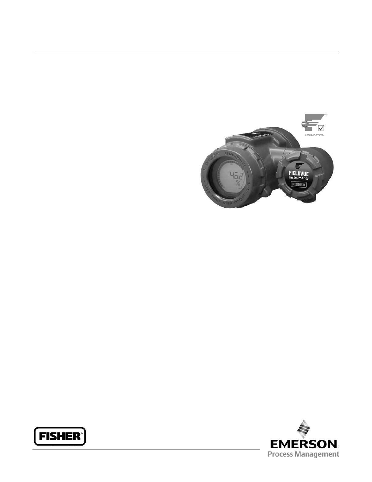
Fisherr FIELDVUEt DLC3020f Digital Level
Controller for F
The FIELDVUE DLC3020f digital level controller is a
fieldbus communicating instrument used to measure
liquid level or the level of interface between two
liquids using displacement sensor technology.
In addition to the normal function of reporting process
level PV, the DLC3020f, using F
protocol, gives easy access to information critical to
process operation and will readily integrate into a new
or existing control system. AMS Suite: Intelligent
Device Manager or the 475 Field Communicator can
be used to configure, calibrate, or test the digital level
controller.
The DLC3020f is also designed to directly replace
pneumatic, analog, or HARTr transmitters/
controllers. It can be mounted on a wide variety of 249
cageless and caged level sensors as well as on other
displacer type level sensors through the use of
mounting adaptors.
OUNDATION fieldbus
OUNDATION
t
fieldbus
W9954-1_DLC3020f
n Dynamic Temperature Compensation Integration
of process fluid temperature, when needed, enables
density compensation to maintain PV accuracy.
Features
n Ease of Use The DLC3020f, a fieldbus level or
interface transmitter, features the latest in user
interface technology. In addition to reporting the
PV, the DLC3020f can act as a PID controller or level
switch.
n Guided Setup and Calibration Leads you through
instrument setup, process fluid selection, and
calibration in an easy‐to‐use format.
n Simple Process Fluid Configuration The capability to
easily select/define process fluids allows for fluid
changes without requiring re-calibration.
n Calibration/Setup Logs Saved in Instrument
Logs, including calibration, instrument setup, and
process fluid data, can be saved for future reference
or re‐use in batch or continuous applications. The
instrument stores up to 30 logs.
n Performance/Reliability State‐of‐the‐art Emerson
advanced electronics provide increased
performance and reliability.
www.Fisher.com
Page 2
Product Bulletin
11.2:DLC3020f
November 2014
Specifications
DLC3020f Digital Level Controller
D103433X012
Available Configurations
Mounts on 249 caged and cageless sensors. Refer to
Fisher Bulletin 11.2:Level
or 34.2:2500 for
information on 249 sensors.
Function: Transmitter, Controller, Switch
Communications Protocol: F
OUNDATION fieldbus
Digital Communication Protocol
OUNDATION fieldbus registered device (ITK 5)
F
Supply Requirements
9 to 32 volts DC, 17.7 mA DC;
instrument is not polarity sensative
Device Inputs
Level Sensor Input (required)
Rotary motion of torque tube shaft is proportional to
buoyant force of the displacer caused by changes in
liquid level or interface level
Process Temperature Compensation Input (optional)
RTD—interface for 2‐ or 3‐wire 100 ohm
platinum RTD
AO Block—F
OUNDATION fieldbus temperature
transmitter
Manual—compensation values manually entered in
the device
LCD Meter Indications
Process Variable in engineering units
Process Variable in percent (%) only
Alternating Process Variable in engineering units and
percent (%)
Optional: Alerts as configured
‐continued‐
Function Block Suite
AI, PID, DI (two), AO (three), ISEL, and an ARTH
function block
Block Execution Times
AI, PID, DI, AI, ISEL: 15 ms
ARTH: 25 ms
Fieldbus Device Capabilities
Backup Link Active Scheduler (BLAS)
Performance
Performance Criteria DLC3020f
Independent Linearity
Accuracy
Repeatability <0.1% of full scale output
Hysteresis <0.10% of output span
Deadband <0.05% of input span
Humidity
Note: At full design span, reference conditions.
1. To lever assembly rotation inputs.
$0.1% of output span
$0.15%
$0.10% (RH9.2% to 90%)
(1)
Minimum Differential Specific Gravity
0.1 SGU with standard volume displacers
Ambient Temperature Effect
The combined temperature effect on zero and span is
less than 0.01% of full scale per degree Celsius over
the operating range -40 to 80_C (-40 to 176_F)
Process Temperature Effect
Temperature compensation can be implemented to
correct for fluid density changes due to process
temperature variations
Electromagnetic Compatibility
Meets EN 61326-1 (First Edition)
Immunity—Industrial locations per Table 2 of
the EN 61326-1 standard.
Emissions—Class A
ISM equipment rating: Group 1, Class A
2
Page 3

DLC3020f Digital Level Controller
D103433X012
Specifications (continued)
Product Bulletin
11.2:DLC3020f
November 2014
Alerts and Diagnostics
Electronic Alerts advise when there is an electronic
error in memory
Operational Range Alerts notify when PV range and
sensor range changes might affect calibration
Rate Limit Alerts indicate rapid rise or fall in displacer,
which can signify abnormal operating conditions
RTD Alerts show health and condition of connected
RTD
Sensor Board Alerts indicate if the device is operating
above or below maximum recommended limits;
advises if the electronic sensor electronics cannot
communicate properly
Input Compensation Error Alerts advise of “Bad” or
“Uncertain” status of AO connection or setup.
Simulate Function
Simulate Active, when enabled, simulates an active
alert without making it visible.
Operating Limits
Process Temperature: See figure 1
(1)
Ambient Temperature
Conditions Normal Limits
Ambient
Temperature
Ambient
Relative
Humidity
-40 to 80_C
(-40 to 176_F)
0 to 95% (non-condensing) 40%
and Humidity
Transport and
Storage Limits
-40 to 85_C
(-40 to 185_F)
Nominal
Reference
25_C
(77_F)
Electrical Classification
Hazardous Area
CSA— Intrinsically Safe, Explosion‐proof,
Division 2, Dust Ignition‐proof
FM— Intrinsically Safe, Explosion‐proof,
Non‐Incendive, Dust Ignition‐proof
ATEX— Intrinsically Safe, Flameproof, Type n
IECEx— Intrinsically Safe, Flameproof, Type n
Electrical Housing
CSA— Type 4X
FM— NEMA 4X, IP66
ATEX— IP66
IECEx— IP66
Mounting Positions
Digital level controllers can be mounted right‐ or
left‐of‐displacer (the position of the instrument when
you are looking at the LCD relative to the displacer)
Construction Materials
Case and Cover: Low‐copper aluminum alloy
Internal: Plated steel, aluminum, and stainless steel;
encapsulated printed wiring boards; Neodymium Iron
Boron Magnets
Electrical Connections
Two 1/2‐14 NPT internal conduit connections; one on
bottom and one on back of terminal box. M20
adapters available.
Weight
Less than 2.7 Kg (6 lbs)
Dimensions
Refer to Fisher Bulletin 34.2:249
for sensor, level
controller, and transmitter dimensions
Options
J Heat insulator J Mountings for Masoneilant,
Yamatake, and Foxborot‐Eckhardt sensors available
1. The pressure/temperature limits in this manual and any applicable standard or code limitation for valve should not be exceeded.
3
Page 4

Product Bulletin
11.2:DLC3020f
November 2014
DLC3020f Digital Level Controller
D103433X012
Ordering Information
When ordering, specify:
1. Type of measurement
J Level or J Interface
2. Process fluid type
J Water, J Saline water, J Saturated water,
J Saturated steam,J Crude oil, J Refined
product,
specified fluid
Note
If Interface indicate both upper and lower fluid types.
3. Process operating conditions
Temperature ______________________________
Fluid density or SG __________________________
J Gas well condensate, or J Customer
Figure 1. Guidelines for Use of Optional Heat
Insulator Assembly
AMBIENT TEMPERATURE (_C)
010 20
HEAT INSULATOR
REQUIRED
NO HEAT INSULATOR NECESSARY
HEAT INSULATOR
REQUIRED
0 20 40 60 80 100 120 140 160
AMBIENT TEMPERATURE (_F)
-325
PROCESS TEMPERATURE (_F)
400
-40 -30
800
0
1
TOO
COLD
-20 -10
-20-40
STANDARD TRANSMITTER
Notes:
1 For process temperatures below -29_C (-20_F) and above 204_C (400_F)
sensor materials must be appropriate for the process (refer to bulletin
34.2:2500)
2. If ambient dew point is above process temperature, ice formation might
cause instrument malfunction and reduce insulator effectiveness.
39A4070‐B
A5494‐1
30 40 50 60
TOO
HOT
70
80
425
400
300
200
100
0
-100
-200
176
PROCESS TEMPERATURE (_C)
Optional Heat Insulator
Note
If Interface indicate fluid density or SG for both upper and
lower fluids.
4. Tag number, as required _____________________
Neither Emerson, Emerson Process Management, nor any of their affiliated entities assumes responsibility for the selection, use or maintenance
of any product. Responsibility for proper selection, use, and maintenance of any product remains solely with the purchaser and end user.
Fisher and FIELDVUE are marks owned by one of the companies in the Emerson Process Management business unit of Emerson Electric Co. Emerson Process
Management, Emerson, and the Emerson logo are trademarks and service marks of Emerson Electric Co. All other marks are the property of their respective
owners.
The contents of this publication are presented for informational purposes only, and while every effort has been made to ensure their accuracy, they are not
to be construed as warranties or guarantees, express or implied, regarding the products or services described herein or their use or applicability. All sales are
governed by our terms and conditions, which are available upon request. We reserve the right to modify or improve the designs or specifications of such
products at any time without notice.
Emerson Process Management
Marshalltown, Iowa 50158 USA
Sorocaba, 18087 Brazil
Chatham, Kent ME4 4QZ UK
Dubai, United Arab Emirates
Singapore 128461 Singapore
www.Fisher.com
If the DLC3020f and a 249 sensor are ordered as an
assembly, and a heat insulator is required for the
application, order the heat insulator as a 249 sensor
option. If the DLC3020f is ordered separately, the heat
insulator is available as a kit. Figure 1 contains
guidelines for use of the optional heat insulator.
E 2010, 2014 Fisher Controls International LLC. All rights reserved.
4
 Loading...