

Page 1
Instruction Manual
D200163X012
Fisherr 4660 High‐Low Pressure Pilot
4660 Pressure Pilot
May 2014
Contents
Introduction 2.................................
Scope of Manual 2.............................
Description 2.................................
Educational Services 2.........................
Specifications 2...............................
Installation 5..................................
Mounting 7..................................
Actuator Mounting 7.......................
Panel Mounting 7..........................
Pipestand Mounting 7......................
Pressure Connections 8........................
Supply Pressure 8..........................
Process Pressure 9.........................
Output Pressure 9.........................
Vent 9.......................................
Operating Information 9.........................
Pilots without Optional Set Point Indication 10.....
Preliminary Adjustments 10.................
Setting the High Set Point 11................
Setting the Low Set Point 11.................
Alternate Set Point Adjustment Procedure 12..
Pilots with Optional Set Point Indication 14........
Setting the High and/or Low Set Point(s) 15....
Prestartup Checks 15..........................
Alignment of the Nozzle Beam 15................
Startup 16...................................
Performance 16................................
Principle of Operation 17........................
Maintenance 17................................
Bourdon Tube/Flapper Assembly
Replacement 18............................
Block‐and‐Bleed Relay Assembly
Replacement 18............................
Low or High Set Point Assembly
Replacement 19............................
Pilots without Set Point Indication 19.........
Pilots with Set Point Indication 19............
Parts Ordering 20...............................
Parts Kits 20...................................
Parts List 22...................................
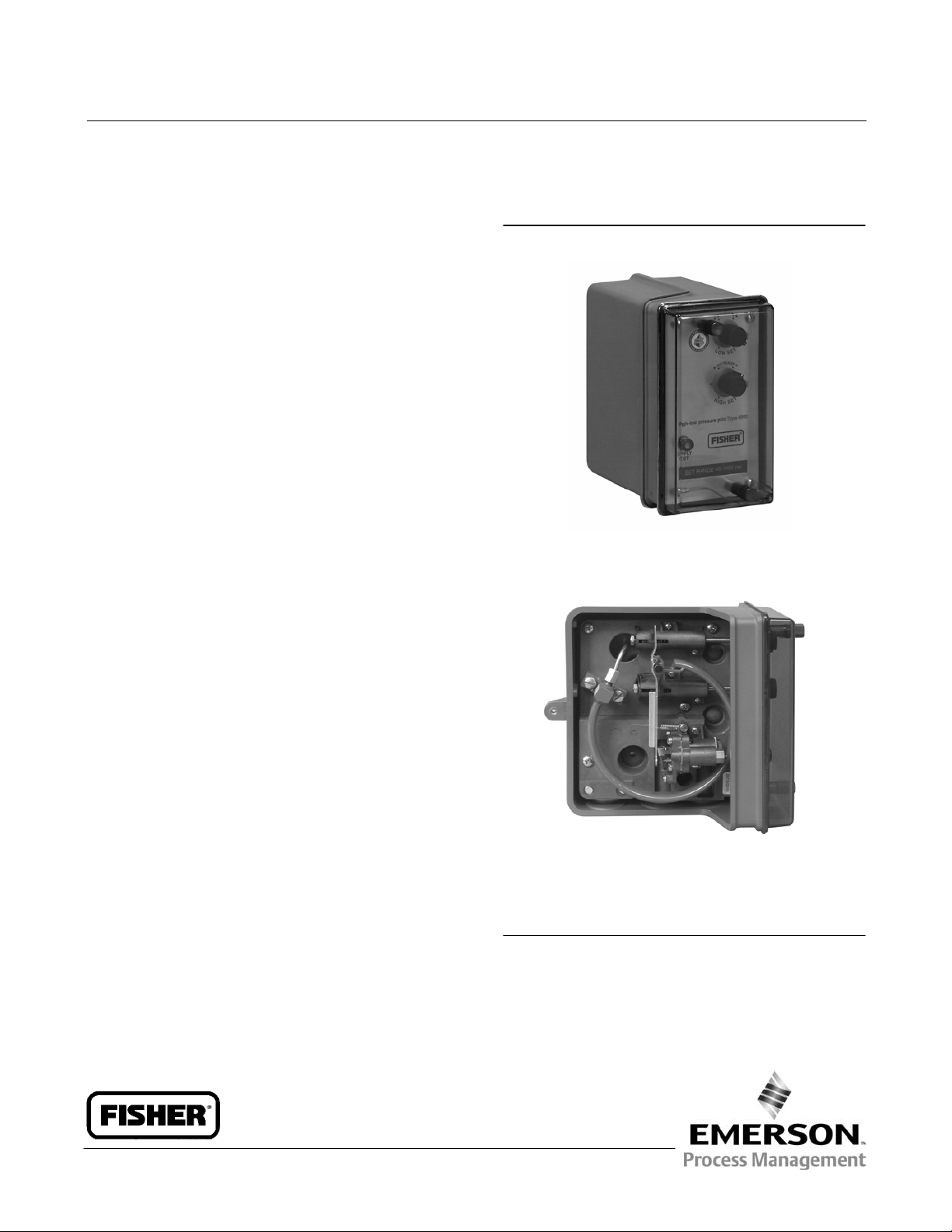
Figure 1. Fisher 4660 High‐Low Pressure Pilot with
Relay
X0231
FRONT VIEW
LEFT SIDE WITH CASE COVER OFF
X0232
www.Fisher.com
Page 2

4660 Pressure Pilot
May 2014
Instruction Manual
D200163X012
Introduction
Scope of Manual
This instruction manual provides installation, operating, maintenance, and parts ordering information for the Fisher
4660 high‐low pressure pilot. Refer to separate instruction manuals for information regarding the control valve
actuator.
Do not install, operate, or maintain a 4660 pressure pilot without being fully trained and qualified in valve, actuator,
and accessory installation, operation and maintenance. To avoid personal injury or property damage it is important to
carefully read, understand, and follow all of the contents of this manual, including all safety cautions and warnings. If
you have any questions about these instructions, contact your Emerson Process Management sales office.
Description
The 4660 high‐low pressure pilot (figure 1) activates emergency shutdown systems for flowlines, production vessels,
and compressors. The pilot can be used with either a single or dual set point capability to maintain full output pressure
when the process is operating within the set point range. The primary switching mechanism in this pilot is a
block‐and‐bleed relay assembly.
Unless otherwise noted, all NACE references are to NACE MR0175‐2002.
Specifications
Specifications for the 4660 high‐low pressure pilot are listed in table 1.
Educational Services
For information on available courses for the 4660 high‐low pressure pilot, as well as a variety of other products,
contact:
Emerson Process Management
Educational Services, Registration
P.O. Box 190
Marshalltown, IA 50158-2823
Phone: 800-338-8158 or 641-754-3771
FAX: 641-754-3431
e‐mail: education@emerson.com
2
Page 3
Instruction Manual
D200163X012
Table 1. Specifications
4660 Pressure Pilot
May 2014
Available Configurations
High‐low, low‐only, or high‐only set point capability
Input Signal
Type: Process pressure sensed with Bourdon tube
Bourdon Tube Ratings: See table 2 or 3
Overpressure Protection: Maximum allowable
emergency process pressures and maximum
allowable process pressures to ensure set point
readjustability are shown in table 4
Output Signal
Zero or full supply pressure (automatically resets)
Supply Pressure
(1)
Normal Operating Pressures: 1.4 to 4.4 bar
(20 to 65 psig)
Medium: Air or natural gas
Air: Supply pressure must be clean, dry air that meets
the requirements of ISA Standard 7.0.01. A maximum
40 micrometer particle size in the air system is
acceptable. Further filtration down to 5 micrometer
particle size is recommended. Lubricant content is
not to exceed 1 ppm weight (w/w) or volume (v/v)
basis. Condensation in the air supply should be
minimized
Natural Gas: Natural gas must be clean, dry, oil‐free,
and noncorrosive. H
S content should not exceed 20
2
ppm.
Steady‐State Air Consumption
Output Signal at Zero:
≤0.134 normal m
3
/hr (≤5 scfh)
(2)(3)
Output Signal at Full Supply Pressure: ≤0.00134
normal m3/hr (≤0.05 scfh)
Set Point Adjustments
Continuously adjustable between 3 and 97% of
Bourdon tube rating; see table 2 or 3 for ranges
Performance in Percentage of Bourdon Tube
Rating
Repeatability: ≤0.25%
Set Point DP
(see table 2 or 3)
min
Single High‐Low Unit: 10% for up to 172.4 bar (2500
psig) Bourdon tubes; 15% for 344.8 and 517.1 bar
(5000 and 7500 psig) Bourdon tubes
Low‐Only and High‐Only Pair: 3%
Trip‐to‐Reset Zone (see table 2 or 3): ≤1.5%
Exhaust Capacity
C
≥15
g
Pilot Supply Flow Requirement
(2)
Pilot requires minimum of 4.02 normal m3/hr
(150 scfh) to activate relay
Operating Conditions
Condition
Ambient
temperature
(1)
Normal Operating
Limits
-59 to 71C (-75 to 160F) 21C (70F)
Nominal
Reference
Operating Influences on Switch Point Sensitivity
Supply Pressure: ≤0.05% of Bourdon tube rating for a
10% change in supply pressure
Ambient Temperature: ≤2% Bourdon tube rating
throughout normal operating limits with nominal
reference
Time: ≤1% of Bourdon tube rating over 30 days at
ambient temperature nominal reference
Process Pressure: Range shift or set point drift can
occur if process pressure exceeds Bourdon tube
rating
Pressure Connections
1/4 NPT internal
Mounting
Panel, rack, pipestand, or actuator
Hazardous Area Classification
Complies with the requirements of ATEX Group II
Category 2 Gas and Dust
-continued-
3
Page 4
4660 Pressure Pilot
May 2014
Table 1. Specifications (continued)
Instruction Manual
D200163X012
Safety Instrumented System Classification
SIL3 capable certified by exida Consulting LLC
Declaration of SEP
Fisher Controls International LLC declares this
product to be in compliance with Article 3 paragraph
Approximate Weight
2.3 kg (5 pounds)
3 of the Pressure Equipment Directive (PED) 97 / 23 /
EC. It was designed and manufactured in accordance
with Sound Engineering Practice (SEP) and cannot
Options
Visual output indication, stainless steel panel
mounting flange, set point indication,
tamper‐resistant front cover
NOTE: Specialized instrument terms are defined in ANSI/ISA Standard 51.1 - Process Instrument Terminology.
1. The pressure and temperature limits in this document and any applicable standard or code limitation should not be exceeded.
2. Normal m
3. Supply pressure at 2.1 bar (30 psig).
3
/hr—normal cubic meters per hour (0C and 1.01325 bar absolute). Scfh—standard cubic feet per hour (60F and 14.7 psia).
bear the CE marking related to PED compliance.
However, the product may bear the CE marking to
indicate compliance with other applicable European
Community Directives.
Table 2. Additional Specifications, Bar
SET POINT DP
0.7
1.7
3.5
6.9
10.4
17.3
34.5
51.8
BOURDON TUBE RATING
6.9
17.2
34.5
69.0
103.4
172.4
344.8
517.2
(2)
689.5
1. Rating indicated on Bourdon tube and set range on front panel are in kPa (1 bar = 100 kPa).
2. NACE compliant material only.
(1)
SET RANGE
0.3 to 6.6
0.6 to 16.6
1.1 to 33.4
2.1 to 67.9
3.2 to 100.2
5.2 to 167.2
10.4 to 334.4
15.6 to 501.5
20.7 to 668.8
(1)
Single High‐
(MINIMUM ALLOWABLE DIFFERENCE
BETWEEN HIGH AND LOW SETTINGS)
Low Unit
103.4
MIN
High‐Only/
Low‐Only Pair
0.3
0.6
1.1
2.1
3.2
5.2
10.4
15.6
20.7
TRIP‐TO‐RESET ZONE
0.2
0.3
0.6
1.1
1.6
2.6
5.2
7.8
10.3
Table 3. Additional Specifications, Psig
BOURDON TUBE
RATING
100
250
500
1000
1500
2500
5000
7500
(1)
10,000
1. NACE compliant material only.
4
SET RANGE
3 to 97
8 to 242
15 to 485
30 to 970
45 to 1455
75 to 2425
150 to 4850
225 to 7275
300 to 9700
(MINIMUM ALLOWABLE DIFFERENCE
SET POINT DP
BETWEEN HIGH AND LOW SETTINGS)
Single High‐
Low Unit
10
25
50
100
150
250
750
1025
1500
MIN
High‐Only/
Low‐Only Pair
3.0
7.5
15.0
30.0
45
75
150
225
300
TRIP‐TO‐RESET ZONE
1.5
3.8
7.5
15.0
23
38
75
113
150
Page 5
Instruction Manual
D200163X012
4660 Pressure Pilot
May 2014
Table 4. Maximum Allowable Process Pressure
BOURDON TUBE RATING
(2)
Bar
6.9
17.2
34.5
69.0
103.4
172.4
344.8
517.2
689.5
6.9
17.2
34.5
69.0
103.4
172.4
344.8
517.2
689.5
1. Normal operating process pressures should not exceed the Bourdon tube rating.
2. Ratings indicated on Bourdon tube are in psig and kPa (1 bar = 100 kPa).
3. Values listed for NACE compliant Bourdon tubes are for a 2% deviation from set point due to overpressure.
Psig Bar
100
250
500
1000
1500
2500
5000
7500
10,000
Maximum Allowable Process Pressure to Insure Set Point Readjustability
100
250
500
1000
1500
2500
5000
7500
10,000
(1)
MAXIMUM ALLOWABLE EMERGENCY PROCESS PRESSURE
Stainless Steel Bourdon Tubes NACE Compliant Bourdon Tubes
(2)
13.8
34.2
69.0
138.0
206.8
344.8
517.2
646.3
N/A
13.8
34.8
51.7
103.5
155.1
172.4
517.2
646.3
N/A
Installation
Psig Bar
200
500
1000
2000
3000
5000
7500
9375
N/A
200
500
750
1500
2250
2500
7500
9375
N/A
69.0
138.0
206.8
258.6
430.9
568.8
758.5
124.0
227.5
344.8
517.2
689.5
13.8
34.2
(3)
13.8
22.3
53.4
89.7
(2)
Psig
200
500
1000
2000
3000
3750
6250
8250
11,000
200
325
775
1300
1800
3300
5000
7500
10,000
If using natural gas as the pneumatic supply medium, natural gas will be used in the pressure connections of the unit
to any connected equipment. The unit will vent natural gas into the surrounding atmosphere, unless it is remote
vented.
WARNING
To avoid personal injury or property damage caused by a sudden release of pressure:
Always wear protective clothing, gloves, and eyewear when performing any installation operations.
Personal injury or property damage may result from fire or explosion if natural gas is used as the supply medium and
appropriate preventative measures are not taken. Preventative measures may include, but are not limited to, one or
more of the following: Remote venting of the unit, re‐evaluating the hazardous area classification, ensuring adequate
ventilation, and the removal of any ignition sources. For information on remote venting of the 4660 pressure pilot,
refer to page 9.
Do not exceed the process pressure values in table 4 or the maximum supply pressure values in table 1.
If installing into an existing application, also refer to the WARNING at the beginning of the Maintenance section in this
instruction manual.
Check with your process or safety engineer for any additional measures that must be taken to protect against process
media.
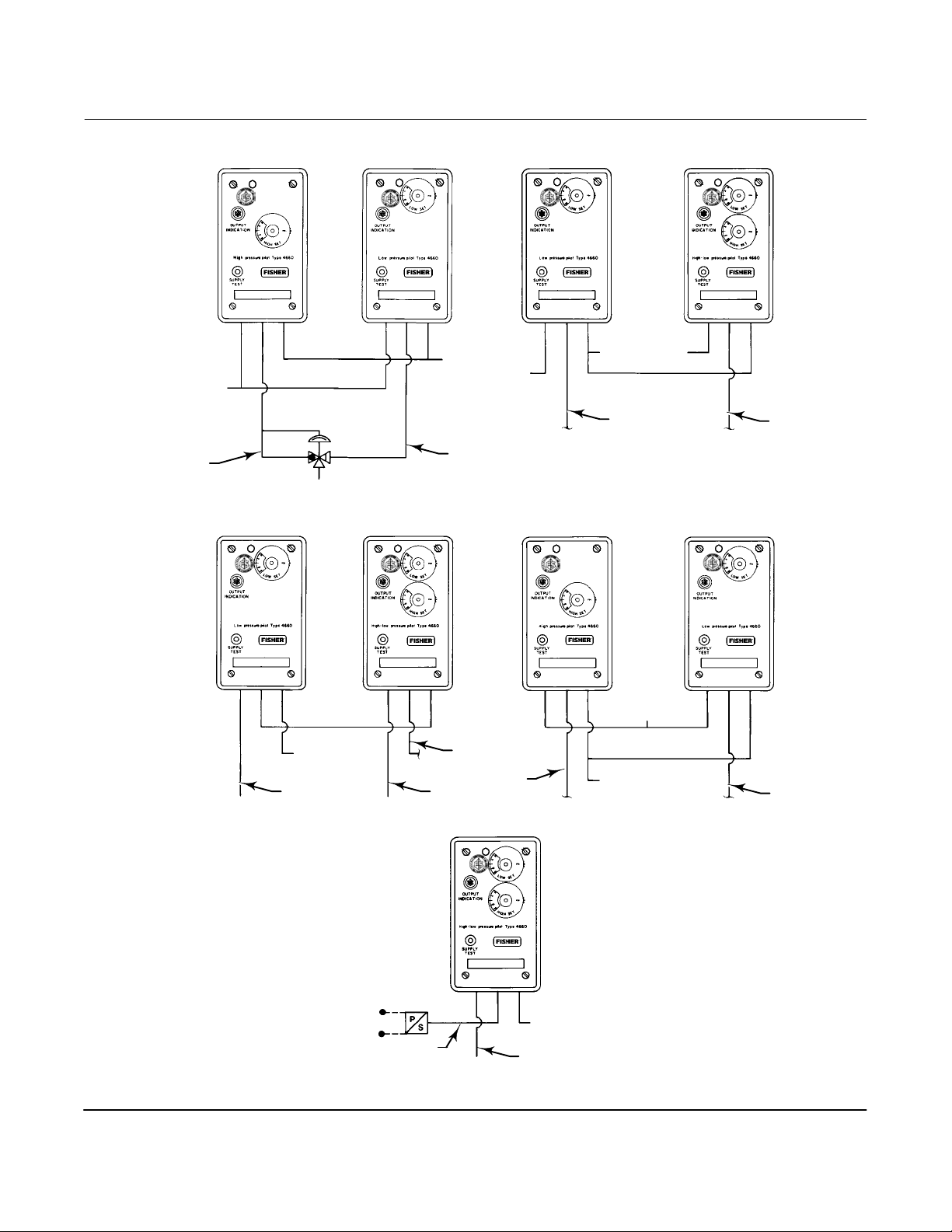
The following instructions describe various mounting and connecting procedures. Pilots may be connected together
to accommodate requirements for single and dual outputs as well as single and dual process pressure lines. Figure 2
shows some typical connections. When a pair of high‐only and low‐only pilots are used to obtain closer set points as
specified by the set point ‐DP
For a two‐segment flow line configuration that adheres to API Specification RP14C, connect as shown in example B
or C.
values in tables 2 and 3 connect the pilots as shown in examples A and D in figure 2.
MIN
5
Page 6
4660 Pressure Pilot
May 2014
Figure 2. Typical Connection Schematics
PROCESS
SUPPLY
PROCESS
NO. 1
SUPPLY
Instruction Manual
D200163X012
PROCESS
NO. 2
OUTPUT
38A6085-B
A. HIGH-ONLY AND LOW-ONLY PILOTS
SENSING A SINGLE PROCESS POINT
AND HAVING A SINGLE OUTPUT
OUTPUT TO SUPPLY
SUPPLY
PROCESS NO. 1
C. LOW-ONLY AND HIGH/LOW PILOTS
WITH SINGLE OUTPUT AND
DIFFERENT PROCESS PRESSURES
38A6087-B
OUTPUT
OUTPUT
PROCESS
NO. 2
OUTPUT
OUTPUT
B. LOW-ONLY AND HIGH/LOW PILOTS
WITH DUAL OUTPUTS AND DIFFERENT
38A6084-B
PROCESS PRESSURES
PROCESS
SUPPLY
D. LOW-ONLY AND HIGH-ONLY PILOTS
WITH DUAL OUTPUTS AND
COMMON PROCESS PRESSURE
38A6086-B
OUTPUT
OUTPUT
C0584-1
6
ELECTRICAL
PRESSURE
SWITCH
39A1578-A
OUTPUT
E. HIGH/LOW PILOT INTERFACED
WITH A PRESSURE SWITCH
SUPPLY
PROCESS
Page 7

Instruction Manual
D200163X012
4660 Pressure Pilot
May 2014
Mounting
Normal installation is with the pilot mounted vertically and with process, supply, and output connections facing
downward as shown in figure 1. All key numbers are shown in figure 8 unless otherwise indicated.
Actuator Mounting
Pilots can be mounted on a control valve actuator as described below.
To yoke‐mount the pilot to an actuator, attach the two‐holed side of the yoke mounting plate (key 75, not shown) to
the spring barrel of the actuator with cap screws and lockwashers (keys 84 and 85, not shown). Then attach the
three‐bossed side of the pilot case (key 2) to the three‐holed side of the yoke mounting plate with the remaining cap
screws and lock washers.
To mount the pilot to the diaphragm casing of an actuator, attach the two‐holed side of the casing mounting plate
(key 75, not shown) to the diaphragm casing of the actuator with the actuator cap screws and nuts. Then attach the
three‐bossed side of the pilot case (key 2) to the three‐holed side of the casing mounting plate with cap screws and
lock washers (keys 84 and 85, not shown).
Panel Mounting
If the pilot is not already equipped with a panel mounting plate (key 75), remove the cover screws (key 6), the cover
(key 4), and the screws (key 21).
For pilots without set point indication, loosen the set screws and remove the knobs (key 67), the locking discs (key 69),
and the front plate (key 74). Insert the panel mounting plate, and reattach the front plate, the locking discs, the knobs,
the cable assembly (key 12), the screws, the cover, and the cover screws.
For pilots with set point indication, loosen the module set screws, and remove the modules and the front plate
(key 74). Insert the panel mounting plate, and reattach the front plate, the modules, the cable assembly (key 12), the
screws, the cover, and the cover screws.
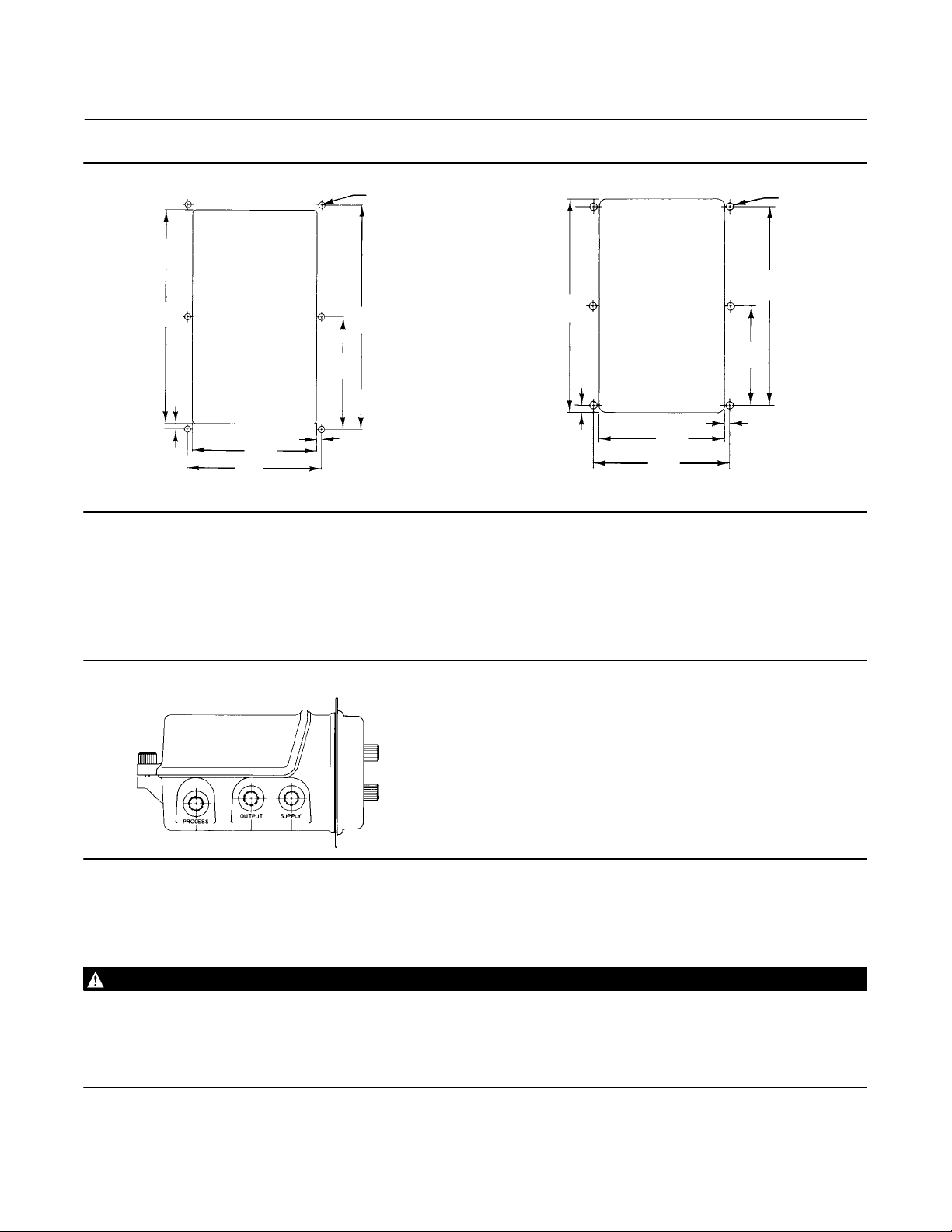
Choose the panel mounting style required to allow for either front or rear removal of the pilot from the panel. Cut a
hole in the panel surface and drill mounting screw holes using the dimensions shown in figure 3.
Note
For either mounting style, the process, output, and supply pressure fittings may be attached to the pilot prior to sliding the pilot
into the cutout. Also, these fittings do not need to be detached from the pilot when removing the pilot from the panel.
Peel off the backing on the panel mount gasket. Apply pressure to the gasket surface to adhere the gasket to the face
of the panel. Slide the pilot into the cutout from the front or rear side of the panel and attach the panel mounting plate
to the panel.
Pipestand Mounting
Pipestand mounting parts are available to mount the pilot to a 2 inch (nominal) horizontal or vertical pipe. Attach the
three‐bossed side of the pilot case (key 2) to the three‐holed side of the pipestand mounting plate (key 75, not shown)
with cap screws and lock washers (keys 84 and 85, not shown). Then attach two pipe clamps (key 86, not shown) to
the pipestand mounting plate, and fasten the pilot to the pipe.
7
Page 8
4660 Pressure Pilot
May 2014
Figure 3. Cutout Dimensions for Panel Mounting
5.2 (0.20)
DIAMETER
HOLES
186
(7.31)
195
(7.69)
98
(3.84)
205
(8.06)
Instruction Manual
D200163X012
5.2 (0.20)
DIAMETER
HOLES
195
(7.69)
98
(3.84)
4 (0.16)
mm
(INCH)
18A3804‐F
A3299‐1
4
(0.16)
109
(4.29)
117
(4.62)
REAR REMOVAL
4 (0.16)
4
(0.16)
109
(4.29)
117
(4.62)
FRONT REMOVAL
Pressure Connections
Standard pressure connections on the 4660 pilot are 1/4 NPT internal. Use 1/4‐ or 3/8‐inch pipe or tubing for process,
output, and supply pressure piping. The locations of pressure connections are shown in figure 4. The vent location is
shown in figure 8.
Figure 4. Location of Pressure Connections
18A3804‐G
Supply Pressure
WARNING
Severe personal injury or property damage may occur from an uncontrolled process if the instrument supply medium is not
clean, dry air or noncorrosive gas. While use and regular maintenance of a filter that removes particles larger than 40
micrometers in diameter will suffice in most applications, check with an Emerson Process Management field office and
industry instrument air quality standards for use with corrosive gas or if you are unsure about the proper amount or
method of air filtration or filter maintenance.
8
Page 9

Instruction Manual
D200163X012
Supply pressure must be clean, dry air or noncorrosive gas that meets the requirements of ISA Standard 7.0.01. A
maximum 40 micrometer particle size in the air system is acceptable. Further filtration down to 5 micrometer particle
size is recommended. Lubricant content is not to exceed 1 ppm weight (w/w) or volume (v/v) basis. Condensation in
the air supply should be minimized.
Alternatively, natural gas may be used as the supply pressure medium. Gas must be clean, dry, oil‐free, and
noncorrosive. H2S content should not exceed 20 ppm.
Use a suitable filter regulator, such as the 67CFR regulator with standard 5 micrometer filter, to remove solid particles
and to maintain the supply pressure source within the normal operating range of 1.4 to 4.4 bar (20 to 65 psig). Refer to
table 1 for the pilot supply flow requirement (relay construction only). As shown in figure 4, connect supply pressure to
the connection marked SUPPLY on the bottom of the pilot case.
4660 Pressure Pilot
May 2014
Process Pressure
Connect process pressure to the connection marked PROCESS on the bottom of the pilot case as shown in figure 4.
When installing process pressure piping, follow accepted practices to ensure accurate transmission of the process
pressure to the pilot. Install shutoff valves, vents, drains, or seal systems as needed in the process pressure line. Install
a needle valve in the process pressure line to dampen pulsations.
Output Pressure
Connect output pressure piping to the connection marked OUTPUT on the bottom of the pilot case as shown in figure
4. Refer to the appropriate control valve or actuator instruction manual to complete the connection of output pressure
piping from the pilot to the loading connection of the control valve actuator.
Vent
WARNING
Personal injury or property damage could result from fire or explosion of accumulated gas, or from contact with hazardous
gas, if a flammable or hazardous gas is used as the supply pressure medium. Because the instrument case and cover
assembly do not form a gas‐tight seal when the assembly is enclosed, a remote vent line, adequate ventilation, and
necessary safety measures should be used to prevent the accumulation or flammable or hazardous gas. A remote vent pipe
alone cannot be relied upon to remove all flammable and hazardous gas.
Vent line piping should comply with local and regional codes, should have adequate inside diameter, and should be be as
short as possible to reduce case pressure buildup.
If a remote vent is required, use 19 mm (3/4‐inch) (minimum inside diameter) pipe for runs up to 6.09 meters (20
feet). For vent piping runs from 6.09 to 30.5 meters (20 to 100 feet), use 25.4 mm (1‐inch) (minimum inside diameter)
pipe. Remove the vent screen (key 20, figure 8) and install a remote vent pipe to exhaust the vented gas to a safe,
well‐ventilated area. The vent, as shown in figure 8, or the end of a remote vent pipe must be protected against the
entrance of all foreign matter that could block the vent. Check the vent periodically to be certain it is not plugged.
Operating Information
For high‐only and low‐only constructions, perform the procedures that are outlined in the adjustments portion of this
section. For high‐only constructions, perform only those procedures that pertain to setting and checking the high set
9
Page 10

4660 Pressure Pilot
May 2014
Instruction Manual
D200163X012
point. For low‐only constructions, perform only those procedures that pertain to setting and checking the low set
point. For high‐low constructions, perform procedures that pertain to both the high and low set points.
WARNING
Avoid personal injury or property damage from an uncontrolled process or sudden release of process pressure. Before
starting any adjustments:
Always wear protective clothing, gloves, and eyewear to avoid personal injury when making adjustments.
Do not remove the actuator from the valve while the valve is still pressurized.
Provide some temporary means of process control before taking the pilot out of service.
Shut off the process pressure line and the supply pressure line, and bleed all of the supply pressure.
Bleed all process pressure from the pilot so that no pressure is contained in the Bourdon tube.
When bleeding the supply or process pressure, natural gas, if used as the supply medium, will seep from the unit into
the surrounding atmosphere. Personal injury or property damage may result from fire or explosion if preventative
measures are not taken, such as adequate ventilation and the removal of any ignition sources.
Use lock‐out procedures to be sure that the above measures stay in effect while you are working on the equipment.
Check with your process or safety engineer for any additional measures that must be taken to protect against process
media.
Pilots Without Optional Set Point Indication
Preliminary Adjustments
Make sure the following steps have been performed completely before setting either the high or low set point
pressures. Key numbers are shown in figure 8.
1. Refer to the WARNING at the beginning of the Operating Information section. Make sure the Bourdon tube contains
no pressure.
2. Install either a pressure gauge or an optional output indicator in the output pressure line.
3. Remove the cover screws and the cover (keys 6 and 4).
4. Unlock each locking disc (key 69) that holds each set point knob in place. Turn the HIGH SET knob clockwise until it
has reached the end of its travel. Turn the LOW SET knob (key 67) counterclockwise until it has reached the end of
its travel.
WARNING
Before continuing on with step 5, read this Warning:
Natural gas, if used as the supply medium, will seep from the unit into the surrounding atmosphere when the SUPPLY TEST
button is pushed in the next step. Personal injury or property damage may result from fire or explosion if preventative
measures are not taken, such as adequate ventilation and the removal of any ignition sources.
5. Turn on the supply pressure. To check that the supply pressure is turned on, push the SUPPLY TEST button located
in the cleanout assembly (key 54) on the front plate (key 74) until a flow sound is heard.
WARNING
To avoid personal injury or property damage caused by a sudden release of pressure, do not exceed the process pressure
values in table 4.
10
Page 11

Instruction Manual
D200163X012
4660 Pressure Pilot
May 2014
6. Connect an external pressure source to the process pressure connection. This external pressure source should be a
regulated air or gas supply that is adjustable to zero. The external pressure source must be capable of supplying a
process pressure that will be equal to or greater than the desired high set point pressure.
7. Continue with the appropriate procedures described below. Replace the cover and cover screws after all
adjustments are completed.
Setting the High Set Point
Note
To ensure that full output pressure will be indicated during the following steps, make sure the first six steps of the Preliminary
Adjustments procedure have been completed before proceeding.
WARNING
To avoid personal injury or property damage caused by a sudden release of pressure, do not exceed the Bourdon Tube
rating (see tables 2 and 3).
To set the high set point pressure, perform the following four steps:
1. Adjust the external pressure source to the desired high set point pressure.
2. Check that full output pressure is being registered by using a pressure gauge installed in the output pressure line or
by using the optional output indicator (key 88). The optional output indicator shows a green color when the output
pressure is at full pressure and black when the output pressure is at zero.
3. Slowly turn the HIGH SET knob counterclockwise until the desired high set point is obtained. The high set point is
obtained when the output pressure of the pilot has changed from full output to zero.
4. Lock the locking disc (key 69).
Setting the Low Set Point
Note
To ensure that full output pressure will be indicated during the following steps:
Make sure that the first six steps of the Preliminary Adjustments procedure found on page 10 have been completed before
proceeding, and
Make sure the difference between the high set point pressure and the low set point pressure is greater than or equal to the
appropriate Set Point DP
To set the low set point pressure, perform the following four steps:
value specified in tables 2 and 3.
MIN
1. Adjust the external pressure source to the desired low set point pressure.
2. Check that full output pressure is being registered by using a pressure gauge installed in the output pressure line or
by using the optional output indicator (key 88). The optional output indicator shows a green color when the output
pressure is at full pressure and black when the output pressure is at zero.
11
Page 12

4660 Pressure Pilot
May 2014
Instruction Manual
D200163X012
3. Slowly turn the low set point knob (key 67) clockwise until the low set point is obtained. The low set point is
obtained when the output pressure of the pilot has changed from full output to zero.
4. Lock the locking disc (key 69).
Alternate Set Point Adjustment Procedure
This procedure may be used to closely approximate the desired high and low set points when no external pressure
source is available to simulate process pressure. If the pilot does not have the optional output indicator (key 88),
provide a means of indicating the output pressure. Refer to figure 5.
Figure 5. Set Point Adjustment Detail
BUTTON
LOW SET POINT
DOTS
POINTER
LOCKING DISC
INDICATION
THUMBWHEEL
LOCKING ARM
HIGH SET POINT
INDICATION
48A3549‐F
39A1578‐A
A3300‐1
WITHOUT SET POINT INDICATION WITH SET POINT INDICATION
Refer to the appropriate procedure below.
Note
Make sure that the first six steps of the Preliminary Adjustments procedure found on page 10 have been completed before
proceeding.
High‐Low Construction
1. Refer to the WARNING at the beginning of the Operating Information section. Make sure the Bourdon tube contains
no pressure.
2. Connect supply pressure to the pilot.
WARNING
Before continuing on with step 3, read this Warning:
Natural gas, if used as the supply medium, will seep from the unit into the surrounding atmosphere when the SUPPLY TEST
button is pushed. Personal injury or property damage may result from fire or explosion if preventative measures are not
taken, such as adequate ventilation and the removal of any ignition sources.
3. Turn on the supply pressure. To check that the supply pressure is on, press the SUPPLY TEST button in the cleanout
assembly (key 54) until a flow sound is heard.
12
Page 13

Instruction Manual
D200163X012
4660 Pressure Pilot
May 2014
4. Turn the HIGH SET knob counterclockwise until the high set point pivot just comes in contact with the flapper. The
pilot should have full output pressure (green indication on the optional output indicator).
5. Refer to table 5 and turn the HIGH SET knob clockwise to correspond to the desired set point value. For example,
with a 690 kPa (100 psig) Bourdon tube, turn the knob five revolutions for a desired high set point of 415 kPa
(60 psig).
Table 5. Alternate Set Point Adjustment
1
2
5
10
20
30
50
100
150
200
(1)
PRESSURE CHANGE PER REVOLUTION
0.4
0.8
2.1
4.1
8.3
12.4
20.7
41.4
62.1
82.7
6
12
30
60
120
180
300
600
900
1200
BOURDON TUBE RATING PRESSURE CHANGE PER DOT
bar Psig bar Psig bar Psig
3.4
6.9
17.2
34.5
69.0
103.4
172.4
344.8
517.2
689.5
1. Six dots per revolution.
50
100
250
500
1000
1500
2500
5000
7500
10,000
0.1
0.1
0.4
0.7
1.4
2.1
3.4
6.9
10.3
13.8
6. Turn the LOW SET knob counterclockwise until the low set point pivot just comes in contact with the flapper,
moving the nozzle beam off the nozzle. The pilot should have zero output pressure (black indication on the optional
output indicator).
7. Refer to table 5 and turn the LOW SET knob clockwise to the desired set point value. For example, with a 690 kPa
(100 psig) Bourdon tube, turn the knob two revolutions for a desired low set point of 165 kPa (24 psig).
8. Lock the locking discs (key 69).
High‐Only Construction
1. Refer to the WARNING at the beginning of the Operating Information section. Make sure the Bourdon tube contains
no pressure.
2. Connect supply pressure to the pilot.
WARNING
Before continuing on with step 3, read this Warning:
Natural gas, if used as the supply medium, will seep from the unit into the surrounding atmosphere when the SUPPLY TEST
button is pushed. Personal injury or property damage may result from fire or explosion if preventative measures are not
taken, such as adequate ventilation and the removal of any ignition sources.
3. Turn on the supply pressure. To check that the supply pressure is on, press the SUPPLY TEST button in the cleanout
assembly (key 54) until a flow sound is heard.
4. Turn the LOW SET knob counterclockwise until it has reached the end of its travel.
5. Turn the HIGH SET knob counterclockwise until the high set point pivot just comes in contact with the flapper. The
pilot should have full output pressure (green indication on the optional output indicator).
6. Refer to table 5 and turn the HIGH SET knob clockwise to correspond to the desired set point value. For example,
with a 690 kPa (100 psig) Bourdon tube, turn the knob five revolutions for a desired high set point of 415 kPa (60
psig).
7. Lock the locking disc (key 69).
13
Page 14

4660 Pressure Pilot
May 2014
Instruction Manual
D200163X012
Low‐Only Construction
1. Refer to the WARNING at the beginning of the Operating Information section. Make sure the Bourdon tube contains
no pressure.
2. Connect supply pressure to the pilot.
WARNING
Before continuing on with step 3, read this Warning:
Natural gas, if used as the supply medium, will seep from the unit into the surrounding atmosphere when the SUPPLY TEST
button is pushed. Personal injury or property damage may result from fire or explosion if preventative measures are not
taken, such as adequate ventilation and the removal of any ignition sources.
3. Turn on the supply pressure. To check that the supply pressure is on, press the SUPPLY TEST button in the cleanout
assembly (key 54) until a flow sound is heard.
4. Turn the HIGH SET knob clockwise until it has reached the end of its travel.
5. Turn the LOW SET knob counterclockwise until the low set point pivot just comes in contact with the flapper,
moving the nozzle beam off the nozzle. The pilot should have zero output pressure (black indication on the optional
output indicator).
6. Refer to table 5 and turn the LOW SET knob clockwise to the desired set point value. For example, with a 690 kPa
(100 psig) Bourdon tube, turn the knob two revolutions for a desired low set point of 165 kPa (24 psig).
7. Lock the locking disc (key 69).
Pilots With Optional Set Point Indication
Make sure the following six steps have been performed completely before setting the high and/or low set point
pressures. Key numbers are shown in figure 8.
1. Refer to the WARNING at the beginning of the Operating Information section. Make sure the Bourdon tube contains
no pressure.
2. Install either a pressure gauge or an optional output indicator (key 88) in the output pressure line.
3. Remove the cover screws (key 6) and the cover (key 4).
WARNING
Before continuing on with step 4, read this Warning:
Natural gas, if used as the supply medium, will seep from the unit into the surrounding atmosphere when the SUPPLY TEST
button is pushed. Personal injury or property damage may result from fire or explosion if preventative measures are not
taken, such as adequate ventilation and the removal of any ignition sources.
4. Turn on the supply pressure. To check that the supply pressure is turned on, press the SUPPLY TEST button located
in the cleanout assembly (key 54) until a flow sound is heard.
WARNING
To avoid personal injury or property damage caused by a sudden release of pressure, do not exceed the process pressure
values in table 4.
14
Page 15

Instruction Manual
D200163X012
5. Connect an external pressure source to the process pressure connection. This external pressure source should be a
regulated air or gas supply that is adjustable to zero. The external pressure source must be capable of supplying a
process pressure that will be equal to or greater than the desired high set point pressure.
6. Continue with the appropriate procedures described below. Replace the cover and cover screws after all
adjustments are completed.
4660 Pressure Pilot
May 2014
Setting the High and/or Low Set Point(s)
1. Adjust the external process pressure source to the desired high or low set point. For example, if the pilot is to trip at
3.4 bar (50 psig), apply 3.4 bar (50 psig) to the pilot. Use a pressure gauge to measure the process pressure.
2. Rotate the locking arm clockwise to unlock the module. Slowly turn the HIGH SET or LOW SET knob until the pilot
trips.
3. Push the small button in the center of the knob with a ball point pen or pencil and rotate the scale with the
thumbwheel on the right hand edge of the module (see figure 5) until the number 50 aligns with the mark on the
left‐hand edge of the module window.
4. Rotate the locking arm counterclockwise to lock the module.
5. Repeat steps 1, 2, and 3 for the other module, if specified.
Prestartup Checks
Before using the pilot in an actual startup, verify that both the high and low set point pressures are set at the desired
pressure settings.
WARNING
To avoid personal injury or property damage caused by a sudden release of pressure, do not exceed the Bourdon Tube
rating (see tables 2 and 3).
1. After the desired low set point pressure has been adjusted, increase the external pressure source pressure until the
output pressure of the pilot is at full output. Do not exceed the set range (see tables 2 and 3) for the appropriate
Bourdon tube range.
2. Increase the external pressure source pressure until the output pressure of the pilot has changed from full output to
zero. Listen carefully. You will hear a quick change in sound when the output changes.
3. Compare the pressure of the external pressure source with the desired high set point setting.
4. If necessary, adjust the high set point pressure by turning the HIGH SET knob clockwise to increase and
counterclockwise to decrease the high set point setting. Once the desired high set point is achieved, rotate the
locking arm to the locked position.
5. Decrease the external pressure source until the output pressure of the pilot is again at full output.
6. Continue to decrease the external pressure source pressure until the output pressure of the pilot has changed from
full output to zero. Listen carefully. You will hear a quick change in sound when the output changes.
7. Compare the pressure of the external pressure source with the desired low set point setting.
8. If necessary adjust the low set point pressure by turning the LOW SET knob (key 67) clockwise to increase and
counterclockwise to decrease the low set point setting. Once the desired low set point is achieved, rotate the
locking arm to the locked position.
Alignment of the Nozzle Beam
Perform this procedure before startup if the self‐aligning disc of the nozzle beam is noticeably misaligned with respect
to the nozzle area of the block‐and‐bleed relay (see figures 7 and 8). Key numbers are shown in figure 8.
15
Page 16

4660 Pressure Pilot
May 2014
Instruction Manual
D200163X012
1. Remove the case cover screw (key 5) and the case cover (key 3).
2. Lift the end of the flapper off the nozzle beam approximately 19 mm (0.75 inch) by moving the opposite end of the
flapper clockwise for a slight rotation.
CAUTION
Be careful not to force the flapper such that the spring (key 18) will become damaged.
3. Release the upper end of the flapper such that the flapper will snap back and contact the nozzle beam.
4. Replace the case cover, and attach it with the case cover screw.
Startup
Verify that the desired high and/or low set point pressures have been set. Refer to the Mounting section for the desired
pilot installation procedures.
Reduce the external process pressure source to zero and disconnect the source from the process
Performance
The performance characteristics shown in figure 6 illustrate several important functional parameters.
Figure 6. Performance Characteristics
TRIP‐TO‐
RESET ZONE
SET POINT
ΔP
100%
OUTPUT
PRESSURE
A2897‐2
PROCESS PRESSURE
SL and SH represent the low and high set points, respectively. The set range is 3 to 97 percent of the Bourdon tube
rating. However, with a single high‐low unit or a high‐only/low‐only pair, there is a limit on how close to each other the
set points can be adjusted. This limit is defined as set point DP
Trip‐to‐reset is the combined effect of pilot dead band and hysteresis. After the pilot has tripped, it will automatically
reset when the process pressure returns to the set range. However, full output is not instantaneous. The difference
between the set point and reset to full output is the trip‐to‐reset zone. This parameter is also a function of the Bourdon
tube rating as shown in figure 6.
MIN
PERCENT OF BOURDON TUBE RATING
CONSTRUCTION
Single High‐Low Unit
High‐Only/Low‐Only Pair
1. 5000 and 7500 psig Bourdon tubes are 15 percent of Bourdon tube rating.
and is shown as SL' and SH'.
MIN
Set Point
DP
MIN
(1)
10
3
Trip‐to‐
Reset Zone
≤1.5
Repeatability
≤0.25
Finally, repeatability is the switch point deviation around the set point as a percentage of the Bourdon tube rating.
16
Page 17

Instruction Manual
D200163X012
4660 Pressure Pilot
May 2014
Principle of Operation
Refer to the schematic in figure 7. The following explanation describes the principle of operation for a high‐low pilot.
Figure 7. Principle of Operation Schematic
LOW SETPOINT PIVOT
HIGH SET POINT PIVOT
BOURDON TUBE
38A3803‐A
A2898‐2
PROCESS PRESSURE
LOW SETPOINT ADJUSTMENT
HIGH SETPOINT ADJUSTMENT
SPRING
FLAPPER
NOZZLE
BEAM
BLOCK AND BLEED
RELAY ASSEMBLY
SUPPLY PRESSURE
OUTPUT PRESSURE
Process pressure is connected to the pilot Bourdon tube sensing element. As the process pressure decreases, the
Bourdon tube contracts; as the process pressure increases, the Bourdon tube expands. While the process pressure
remains above the low set point and below the high set point, the flapper does not contact either set point pivot, but
contacts the nozzle beam. This keeps the relay nozzle capped off, maintaining full output pressure.
A decrease in process pressure below the low set point, or an increase in process pressure above the high set point
causes the flapper to contact the respective low or high set point pivot and uncap the relay nozzle. This trips the relay
assembly, which blocks supply pressure and vents (bleeds) the output pressure to zero.
When the process pressure returns to a value between the low and high set points, the flapper no longer contacts one
of the set point pivots, but contacts the nozzle beam, again capping off the relay nozzle. This resets the relay
assembly, restoring full output pressure.
Maintenance
Select the appropriate maintenance procedure, and perform the numbered steps. Each procedure requires that supply
pressure and process pressure be shut off before beginning maintenance. All key numbers are shown in figure 8.
17
Page 18

4660 Pressure Pilot
May 2014
Instruction Manual
D200163X012
WARNING
Avoid personal injury or property damage from an uncontrolled process or sudden release of process pressure. Before
starting disassembly:
Always wear protective clothing, gloves, and eyewear when performing any maintenance operations.
Do not remove the actuator from the valve while the valve is still pressurized.
Provide some temporary means of process control before taking the pilot out of service.
Shut off the process pressure line and the supply pressure line, and bleed all of the supply pressure.
Bleed all process pressure from the pilot so that no pressure is contained in the Bourdon tube.
When bleeding the supply or process pressure, natural gas, if used as the supply medium, will seep from the unit into
the surrounding atmosphere. Personal injury or property damage may result from fire or explosion if preventative
measures are not taken, such as adequate ventilation and the removal of any ignition sources.
Use lock‐out procedures to be sure that the above measures stay in effect while you are working on the equipment.
Check with your process or safety engineer for any additional measures that must be taken to protect against process
media.
Bourdon Tube/ Flapper Assembly Replacement
Obtain the Bourdon tube/flapper assembly kit listed in the parts kit section.
1. Remove the case cover screw (key 5) and the case cover (key 3).
2. Unhook the flapper spring (key 18) from the Bourdon tube/flapper assembly. Inspect the flapper spring, and replace
it if the coils are separated when the spring is in its free state with no extension.
3. Loosen the screws (key 27), and remove the Bourdon tube/flapper assembly.
4. Disconnect the process tubing (key 8).
5. Install a new Bourdon tube/flapper assembly and tighten the machine screws.
6. Reconnect the process tubing to the Bourdon tube/flapper assembly.
7. Reconnect the flapper spring to the Bourdon tube/flapper assembly.
8. Replace the case cover, and attach it with the case cover screw.
9. If appropriate, place a new label (key 73) with the new Bourdon tube set range on the front plate (key 74).
10. Reset the high and/or low set points according to the procedures presented in the Operating Information section.
11. Refer to the alignment of the nozzle beam procedures in the Operating Information section.
Block‐and‐Bleed Relay Assembly Replacement
Obtain the block‐and‐bleed relay assembly listed in the parts kit section.
1. Make sure supply pressure is shut off and vented.
2. Remove the case cover screw (key 5) and the case cover (key 3).
3. Remove the machine screws (key 57).
4. Remove the block‐and‐bleed relay assembly.
5. Make sure the O‐rings are in place on the bottom flange, then install a new block‐and‐bleed relay assembly.
6. Tighten the machine screws.
18
Page 19

Instruction Manual
D200163X012
7. Refer to the alignment of the nozzle beam procedure in the Operating Information section.
8. Replace the case cover, and attach it with the case cover screw.
9. Reset the high and/or low set points according to the procedures presented in the Operating Information section.
4660 Pressure Pilot
May 2014
Low or High Set Point Assembly Replacement
Obtain the set point assembly listed in the parts kit section, then perform one or the other of the following procedures.
Pilots Without Set Point Indication
Note
New locking wedges (key 71) must be installed when performing this procedure. Refer to the parts list section and obtain the
correct quantity. Two are required for low or high versions. Four are required for high‐low versions.
1. Perform steps 1 through 4 of the Bourdon tube/flapper assembly replacement procedure.
2. Remove the knob (key 67) by loosening the knob set screw and pulling it away from the front plate (key 74).
3. Remove the locking disc (key 69) and the locking nut (key 70).
4. Remove the screws (key 68) and the switch point assembly.
5. Remove the locking wedges (key 71).
6. Install the new set point assembly and tighten the screws.
7. Install new locking wedges over the set point stem.
8. Apply lubricant (key 81) to the locking nut threads and install it finger‐tight.
9. Tighten the locking nut to 5.6 Nm (50 lbfin) of torque. Back the nut out one‐quarter turn.
10. Re‐tighten the locking nut to 1.1 Nm (10 lbfin) of torque.
11. Install the knob on the stem and tighten the set screws. Attempt to rotate the knob. If the knob rotates, repeat
steps 9 and 10.
12. Loosen the set screws and remove the knob.
13. Repeat steps 1 through 12 if both set point assemblies are to be replaced on a high‐low version of the pilot.
14. Install the front plate and the panel mounting plate (if required).
15. Install the locking disc(s) with the tab(s) as close to 90 degrees to the right of vertical as possible.
16. If the locking disc(s) cannot be installed as described in step 15, install the tab(s) between vertical and 90 degrees,
rather than beyond the 90 degree position.
17. Perform steps 6 through 11 of the Bourdon tube/flapper assembly replacement procedure.
Pilots With Set Point Indication
1. Perform steps 1 through 4 of the Bourdon tube/flapper assembly replacement procedure.
2. Remove the set point indication module by loosening the set screws that attach the module to the set point
assembly stem, and pulling it away from the front plate (key 74).
3. Remove the screws (key 68) and the set point assembly.
4. Install the new set point assembly and tighten the screws.
19
Page 20

4660 Pressure Pilot
May 2014
Instruction Manual
D200163X012
5. Repeat steps 2 through 4 if both set point assemblies are to be replaced on a high‐low version of the pilot.
6. Install the front plate and the panel mounting plate (if required).
7. Align the three posts on the set point indication module(s) with the three holes on the front plate.
8. Push the set point indication module(s) flush with the front plate and tighten the set screws. Do not overtighten the
set screws.
9. Perform steps 6 through 11 of the Bourdon tube/flapper assembly replacement procedure.
Parts Ordering
Whenever corresponding with your Emerson Process Management sales office about this equipment, always mention
the pilot serial number located on the nameplate (key 76, figure 8) on the rear of the pilot. When ordering
replacement assemblies or parts, refer to the 11‐character part number of each assembly or part as found in the
following parts list.
WARNING
Use only genuine Fisher replacement parts. Components that are not supplied by Emerson Process Management should
not, under any circumstances, be used in any Fisher instrument. Use of components not supplied by Emerson Process
Management may void your warranty and hazardous area approval, might adversely affect the performance of the
instrument, and could cause personal injury and property damage.
Parts Kits
Description Part Number
Block‐and‐Bleed Relay Assembly
Block‐and‐Bleed Relay Replacement Assembly
(Includes block‐and‐bleed assembly
and keys 53 and 57) R4660XAVR52
Bourdon Tube/Flapper Assembly
Bourdon Tube/Flapper Assembly (Includes
Bourdon tube/flapper and keys 18, 27, 73)
Stainless Steel Bourdon Tube
Bourdon Tube Rating
6.9 bar (100 psig) R4660XBTFJ2
17.2 bar (250 psig) R4660XBTFK2
34.5 bar (500 psig) R4660XBTFL2
69.0 bar (1000 psig) R4660XBTFM2
103.4 bar (1500 psig) R4660XBTFN2
344.8 bar (5000 psig) R4660XBTFR2
517.1 bar (7500 psig) R4660XBTFS2
Key Description Part Number
NACE Compliant Bourdon Tube
Bourdon Tube Rating
6.9 bar (100 psig) R4660XBTF12
17.2 bar (250 psig) R4660XBTF22
34.5 bar (500 psig) R4660XBTF32
69.0 bar (1000 psig) R4660XBTF42
103.4 bar (1500 psig) R4660XBTF52
172.4 bar (2500 psig) R4660XBTF62
344.8 bar (5000 psig) R4660XBTF72
517.1 bar (7500 psig) R4660XBTF82
689.5 bar (10,000 psig) R4660XBTF92
Front Cover Assembly
Front Cover Assembly (Includes keys 4,
6, 12, and 19) R4660XFCA22
20
Page 21

Instruction Manual
D200163X012
Figure 8. 4660 Pilot Assembly
4660 Pressure Pilot
May 2014
SWITCH PT LOW ASSY
SWITCH PT HIGH ASSY
SET POINT KNOB
OR SET POINT
INDICATION ASSY
RELAY ASSY
BOURDON TUBE/
FLAPPER ASSY
APPLY SEALANT
48A3536‐H
Key Description Part Number
Output Indicator
Output Indicator (Includes keys 13, 14,
88, 89, 90, and 91) R4660X0PUT2
Set Point Assembly
Set Point Assembly
No Set Point (Includes keys 67, 69,
70, and 71) R4660XSPA32
Low Set Point (Includes set point
assembly and keys 67, 68, 69, 70, and 71) R4660XSPA22
High Set Point (Includes set point
assembly and keys 67, 68, 69, 70, and 71) R4660XSPA12
Key Description Part Number
Set Point Indicator
Set Point Indicator (Includes set
point assembly and adjustment key)
High Set Point
Bourdon Tube Rating
6.9 bar (100 psig) R4660XSP1A2
17.2 bar (250 psig) R4660XSP1B2
34.5 bar (500 psig) R4660XSP1C2
69.0 bar (1000 psig) R4660XSP1D2
103.4 bar (1500 psig) R4660XSP1E2
172.4 bar (2500 psig) R4660XSP1F2
344.8 bar (5000 psig) R4660XSP1G2
517.1 bar (7500 psig) R4660XSP1H2
689.5 bar (10,000 psig) R4660XSP1T2
21
Page 22

4660 Pressure Pilot
May 2014
Instruction Manual
D200163X012
Description Part Number
Set Point Indicator (continued)
Set Point Indicator (Includes set
point assembly and adjustment key)
Low Set Point
Bourdon Tube Rating
6.9 bar (100 psig) R4660XSP1J2
17.2 bar (250 psig) R4660XSP1K2
34.5 bar (500 psig) R4660XSP1L2
69.0 bar (1000 psig) R4660XSP1M2
103.4 bar (1500 psig) R4660XSP1N2
172.4 bar (2500 psig) R4660XSP1P2
344.8 bar (5000 psig) R4660XSP1R2
517.1 bar (7500 psig) R4660XSP1S2
689.5 bar (10,000 psig) R4660XSP1U2
Supply Test Plunger Assembly
Supply Test Plunger Assembly R4660XSTP22
Tamper‐Resistant Cover
Tamper‐Resistant Cover (Includes hex
tool and key 6) R4660XTPC12
Parts List
Note
Part numbers are shown for recommended spares only. For part
numbers not shown, contact your Emerson Process Management sales
office.
Key Description Part Number
10 Flapper Spring Support, stainless steel
11 Blow‐Out Plug, silicone
12 Cable Assembly, stainless steel/nylon
13 Cover Plate, stainless steel
w/o output indication
w/output indication
14* Cover Plate Gasket, chloroprene 18A1052X012
18 Flapper Spring, stainless steel
19 Cable Screw, stainless steel
20 Vent Screen, stainless steel
21 Machine Screw, stainless steel (4 req'd)
22 Self‐Tapping Screw, stainless steel (5 req'd)
23* O‐Ring, nitrile (3 req'd) 1B885506992
24* O‐Ring, nitrile (3 req'd) 18A1088X012
25* O‐Ring, nitrile 1D2375X0022
26 Cap Screw, stainless steel (2 req'd)
1/4 NPT internal process connection
27 Machine Screw, stainless steel (2 req'd)
28 Machine Screw,stainless steel (3 req'd)
54 Cleanout Assembly
57 Machine Screw, stainless steel (2 req'd)
67 Knob (w/o set point indication)
68 Screw, stainless steel
69 Locking Disc, PPO
(w/o set point indication)
70 Locking Nut, aluminum/PTFE anodized
(w/o set point indication)
71 Locking Wedge, PPO
(w/o set point indication)
73 Range Label
(2)
(1)
(1)
(1)
(2)
Key Description
1 Base, hard coat anodized aluminum
w/duplex seal
2 Case, polyester
3 Case cover, polyester
4 Cover, polyester
5 Case Cover Screw, stainless steel/polyester
6 Cover Screw, stainless steel/polyester (2 req'd)
7 Process Block, 316 stainless steel
1/4 NPT internal process connection
8 Process Tubing,
stainless steel
For all Bourdon Tube ranges
up to 170 bar (2500 psig)
For Bourdon tube ranges
350 bar (5000 psig) or over
NACE compliant
For all Bourdon Tube ranges
up to 170 bar (2500 psig)
For Bourdon tube ranges
350 bar (5000 psig) or over
22
74 Front Plate, stainless steel
w/o Output Indication
Low Set
High Set
High/Low Set
w/ Output Indication
Low Set
High Set
High/Low Set
75 Mounting Plate, stainless steel (not shown)
Panel Mounting
Actuator Yoke Mounting
Actuator Casing Mounting
Pipestand Mounting
76 Nameplate, stainless steel
77 Self‐Tapping Screw, stainless steel(4 req'd)
81 Lubricant, Loctite
76764, or 76775),
84 Cap Screw, pl steel (not shown)
Actuator Yoke Mounting (5 req'd)
Actuator Casing Mounting (3 req'd)
Pipestand Mounting (3 req'd)
*Recommended spare parts
1.One required for high or low set point versions; two required for high/low versions.
2.Two required for high or low set point versions; four required for high/low versions.
Silver Grade Anti‐Seize (76759,
Page 23

Instruction Manual
D200163X012
4660 Pressure Pilot
May 2014
Key Description
85 Lock Washer, pl steel (not shown)
Actuator Yoke Mounting (5 req'd)
Actuator Casing & Pipestand
Mounting (3 req'd)
86 Pipe Clamp, pl steel (not shown)
Pipestand Mounting (2 req'd)
87 Sealant, Loctite 222 Low Strength Threadlocker
(not furnished with pilot)
Key Description Part Number
88 Output Indicator
89 Elbow Fitting, stainless steel
(output indicator) (2 req'd)
90 Tubing, Nylon (output indicator)
91 Tubing, polyethylene (output indicator (2 req'd)
92* Gasket, Nitrile (for panel mounting) 28A4549X012
--- Hex Tool, alloy steel (not shown)
Tamper‐Resistant Cover
*Recommended spare parts
23
Page 24

4660 Pressure Pilot
May 2014
Instruction Manual
D200163X012
Neither Emerson, Emerson Process Management, nor any of their affiliated entities assumes responsibility for the selection, use or maintenance
of any product. Responsibility for proper selection, use, and maintenance of any product remains solely with the purchaser and end user.
Fisher is a mark owned by one of the companies in the Emerson Process Management business unit of Emerson Electric Co. Emerson Process Management,
Emerson, and the Emerson logo are trademarks and service marks of Emerson Electric Co. All other marks are the property of their respective owners.
The contents of this publication are presented for informational purposes only, and while every effort has been made to ensure their accuracy, they are not
to be construed as warranties or guarantees, express or implied, regarding the products or services described herein or their use or applicability. All sales are
governed by our terms and conditions, which are available upon request. We reserve the right to modify or improve the designs or specifications of such
products at any time without notice.
Emerson Process Management
Marshalltown, Iowa 50158 USA
Sorocaba, 18087 Brazil
Chatham, Kent ME4 4QZ UK
Dubai, United Arab Emirates
Singapore 128461 Singapore
www.Fisher.com
24
1982, 2014 Fisher Controls International LLC. All rights reserved.
 Loading...