

Page 1
4660 Pressure Pilot
D200051X012
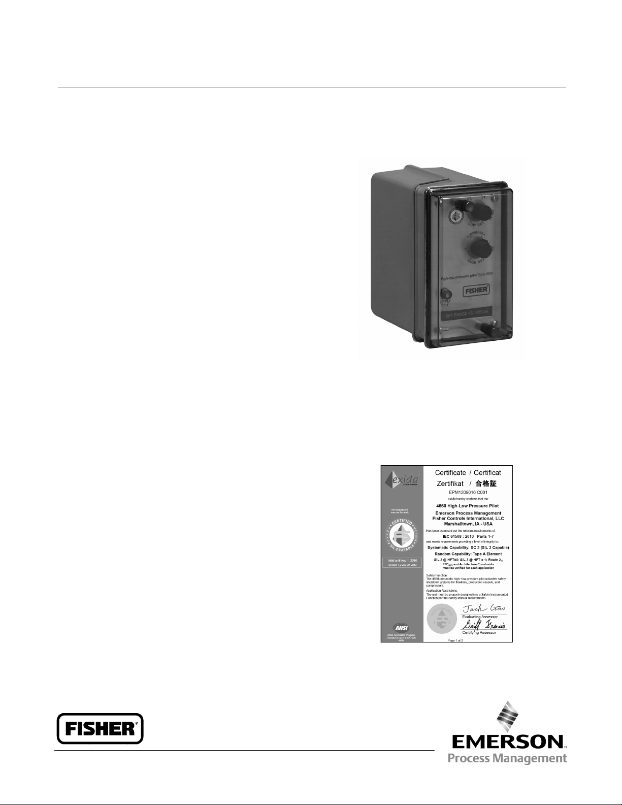
Fisherr 4660 High-Low Pressure Pilot
The Fisher 4660 pneumatic high-low pressure pilot
activates safety shutdown systems for flowlines,
production vessels, and compressors. This pilot is
available with either single or dual set point capability,
using switch points to maintain full output pressure
when the process pressure is within the set point
range. If the process pressure is outside this range, the
pilot switches from full output pressure to zero output
pressure.
The primary switching mechanism in this pilot is a
block-and-bleed relay assembly. This construction can
be used in both block-and-bleed and bleed-only
systems.
Unless otherwise noted, all NACE references are to
NACE MR0175-2002.
X0231
Product Bulletin
34.5:4660
January 2014
Features
n Safety Certification—The 4660 is certified for use in
Safety Instrumented System (SIS) applications.
Certification is by exida Consulting LLC, a global
provider of functional safety and control system
security (see figure 1). SIS certification is identified
on the product by a label affixed to the case.
The functional safety assessment was performed to
the requirements of IEC 61508: ed2, 2010, SIL3 for
mechanical components.
n Superior Performance—Repeatability meets the U.S.
Minerals Management Service test tolerances
referenced in Outer Continental Shelf (OCS) Order
No. 5 and defined in the American Petroleum
Institute (API) RP14C standard.
n Cost-Effective Design—One pilot provides either a
high-low function or a single switch point,
whichever the application requires.
FISHER 4660 HIGH-LOW PRESSURE PILOT
WITH BLOCK AND BLEED RELAY
Figure 1. exida Certificate
www.Fisher.com
Page 2
Product Bulletin
34.5:4660
January 2014
4660 Pressure Pilot
D200051X012
n NACE Conformance—A NACE compliant Bourdon
tube is available for those applications where the
pilot must meet the requirements of NACE
MR0175-2002.
n Environmental Packaging—Construction materials
have been selected to protect the pilot from
corrosive environments such as the salt spray
atmosphere of offshore platforms.
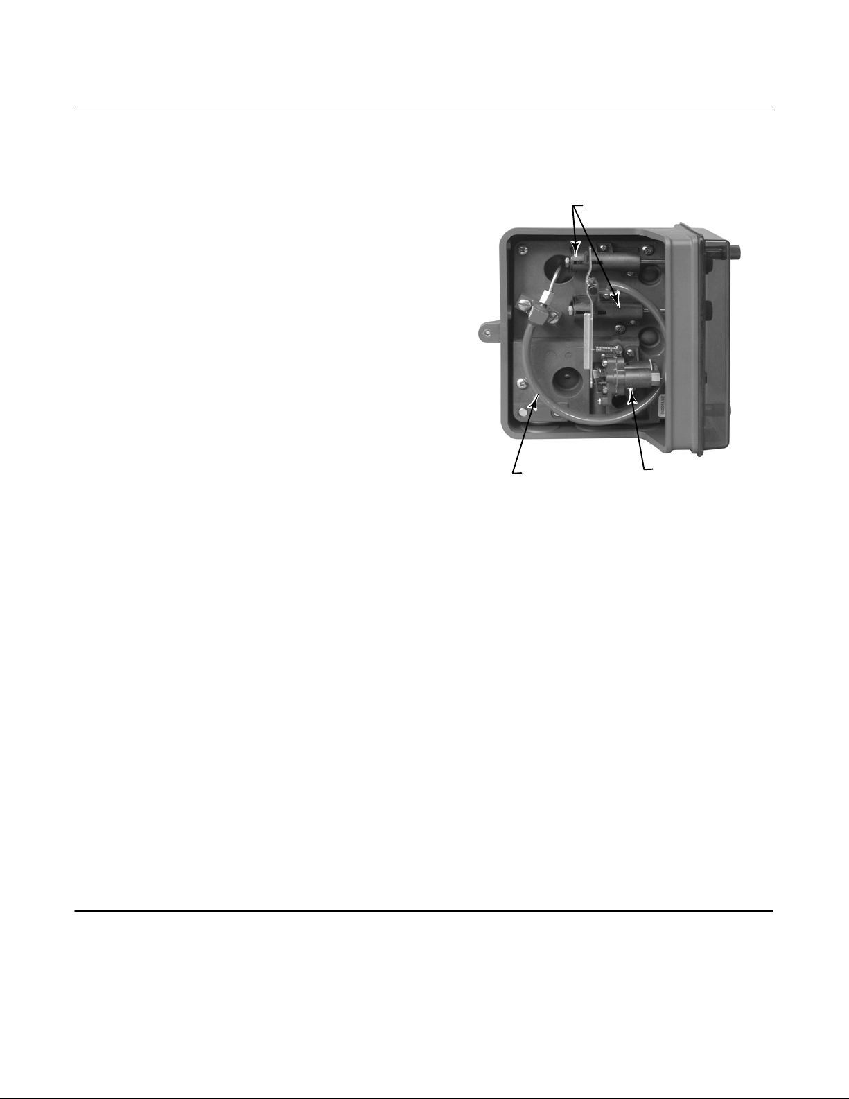
n Reliable Operation—The pilot uses a field-proven
Bourdon tube process pressure sensing element,
shown in figure 2, that reduces maintenance by
eliminating the need for wetted dynamic O-rings.
n Reduced Air/Gas Consumption—The 4660
pneumatic high-low pressure pilot is an energy
efficient choice. The low bleed relay provides a
steady state consumption rate that is less than the
6 SCFH requirement set for the oil and gas industry
by the US Environmental Protection Agency (New
Source Performance Standards Subpart OOOO,
EPA-HQ-QAR-2010-0505).
n Vibration Resistance—The rugged Bourdon tube
sensing element and shock-absorbing switch points
dampen the effects of vibration while maintaining
performance.
n Set Point Accuracy—Standard high-resolution set
point adjustments are easy to set, non-interactive,
and can be locked in place to maintain the desired
set point. The optional set point indication
assemblies on the front panel are easy to read and
let you simply dial in the desired set point.
Figure 2. Fisher 4660 High-Low Pressure Pilot with
Block and Bleed Relay; Left Side with Case Cover Off
SET POINT ADJUSTMENTS
X0232
n Easy Maintenance—Simple modular construction
BOURDON TUBE
BLOCK AND
BLEED RELAY
plus a line of prepackaged parts kits makes pilot
maintenance fast and easy.
n Installation Versatility—Panel, rack, pipestand, or
actuator mounting is available to meet field
requirements.
n Operational Indications—A supply pressure test
function is provided. The optional output indicator
lets you check at a glance whether the pilot output
pressure is at full output or zero output pressure.
Table of Contents
Features 1.....................................
Principle of Operation 6.........................
Performance 6.................................
Applications 7.................................
2
Installation 7..................................
Ordering Information 11.........................
Application 11................................
Construction 11...............................
Page 3

4660 Pressure Pilot
D200051X012
Specifications
Product Bulletin
34.5:4660
January 2014
Available Configurations
J High-low, J low-only, or J high-only set point
capability
Input Signal
Type: Process pressure sensed with a Bourdon tube
Bourdon Tube Ratings: See table 1 or 2
Overpressure Protection: Maximum allowable
emergency process pressures and maximum
allowable process pressures to ensure set point
readjustability are shown in table 3
Output Signal
J Zero pressure or J full supply pressure
(automatically resets)
Supply Pressure
(1)
Normal Operating Pressure: 1.4 to 4.4 bar
(20 to 65 psig)
Medium: Air or natural gas
(2)
Quality: Should be dry with solid particles removed
Steady-State Air Consumption
(3)
Output Signal at 0 psig: ≤0.134 normal m3/hr
(≤5 scfh)
Output Signal at Full Supply Pressure:
≤0.00134 normal m3/hr (≤0.05 scfh)
Exhaust Capacity
≥15
C
g
Construction Materials
Case and Cover: Polyester
Front Cover: Tinted polycarbonate with
scratch-resistant coating
Base: Hard-anodized nickel-sealed aluminum alloy
Bourdon Tube:
J S31600 SST or J NACE compliant
material
Relay Body, Relay Flange, Nozzle/Flapper Assembly
Orifice Block, and Switch Point. Housings: Glass-filled
polyphenylene sulfide
Relay Diaphragm: Fluorosilicone/Polyester
Relay Discs: Fluorosilicone
Process Pressure Block, Tubing, Front Plate, Flapper,
Linkages, and Other Major Metal Parts: Stainless steel
Gaskets: Chloroprene and nitrile
O-Rings.
Relay: Nitrile
Switchpoint Assembly: Nitrile impregnated with
molybdenum disulphide
Base/Case: Nitrile
Operating Conditions
Condition Normal Operating Limits
Ambient
Temperature
(1)
Nominal
Reference
-59 to 71_C (-75 to 160_F) 21_C (70_F)
Set Point Adjustments
Continuously adjustable between 3% and 97% of
Bourdon tube rating; see table 1 or 2 for ranges
Performance in Percentage of Bourdon Tube Rating
Repeatability:
Set Point ΔP
≤0.25%
.
min
(See table 1 or 2)
Single High-Low Unit: 10% for up to 170 bar (2500
psig) Bourdon tubes; 15% for 350, 500, and 700
(NACE) bar (5000, 7500, and 10,000 (NACE) psig)
Bourdon tubes
Low-Only and High-Only Pair: 3%
Trip-to-Reset Zone: ≤1.5% (see table 1 or 2)
Operating Influences on Switch Point Sensitivity
Supply Pressure: ≤0.05% of Bourdon tube rating for a
10% change in supply pressure
Ambient Temperature: ≤2% of Bourdon tube rating
throughout normal operating limits with nominal
reference
Time: ≤1% of Bourdon tube rating over 30 days at
ambient temperature nominal reference
Process Pressure: Range shift or set point drift can
occur if process pressure exceeds the Bourdon tube
rating
Pressure Connections
1/4 NPT internal
-continued-
3
Page 4
Product Bulletin
34.5:4660
January 2014
Specifications (continued)
4660 Pressure Pilot
D200051X012
Mounting
J Panel, J rack, J pipestand, or J actuator
Safety Instrumented System Classification
SIL3 capable certified by exida Consulting LLC
Approximate Weight
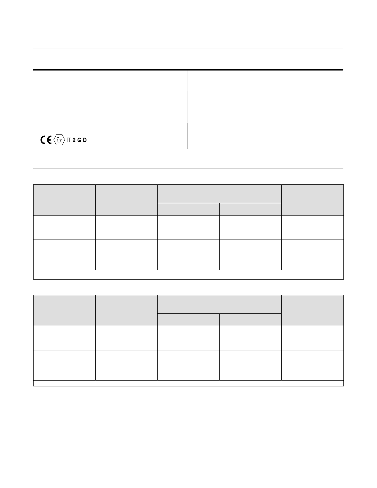
Hazardous Area Classification
Complies with the requirements of ATEX Group II
Category 2 Gas and Dust
2.3 kg (5 pounds)
Options
J Visual output indication J stainless steel panel
mounting flange,
J tamper-resistant front cover
NOTE: Specialized instrument terms are defined in ANSI/ISA Standard 51.1 - Process Instrument Terminology.
1. The pressure/temperature limits in this document and any applicable standard or code limitation for valve should not be exceeded.
2. Natural gas to contain no more than 20 ppm of H
3. Normal m
3
/h--Normal cubic meters per hour at 0_C and 1.01325 bar, absolute. Scfh--Standard cubic feet per hour at 60_F and 14.7 psia.
S.
2
Table 1. Additional Specifications, Bar
BOURDON TUBE
7
17
35
70
100
170
350
500
700
1. Rating indicated on Bourdon tube and set range on front panel are in kPa (1 bar = 100 kPa).
2. Available in NACE compliant material only.
RATING
(2)
(1)
SET RANGE
0.6 to 16.6
1.1 to 33.4
2.1 to 67.9
3.2 to 100.2
5.2 to 167.2
10.4 to 334.4
15.6 to 501.5
20.7 to 668.8
(1)
Single High-Low Unit
0.3 to 6.6
SET POINT ΔP
ALLOWABLE DIFFERENCE
BETWEEN HIGH AND LOW SETTINGS)
0.7
1.7
3.5
6.9
10.3
17.2
51.7
70.7
103.4
(MINIMUM
MIN
J set point indication, and
High-Only/
Low-Only Pair
0.2
0.5
1.0
2.1
3.1
5.2
10.3
15.5
20.7
TRIP-TO-RESET ZONE
≤0.1
0.3
0.5
1.0
1.6
2.6
5.2
7.8
10.3
Table 2. Additional Specifications, Psig
BOURDON TUBE
RATING
100
250
500
1000
1500
2500
5000
7500
(1)
10,000
1. Available in NACE compliant material only.
4
SET RANGE
3 to 97
8 to 242
5 to 485
30 to 970
45 to 1455
75 to 2425
150 to 4850
225 to 7275
300 to 9700
SET POINT ΔP
ALLOWABLE DIFFERENCE
BETWEEN HIGH AND LOW SETTINGS)
Single
High-Low Unit
10
25
50
100
150
250
750
1025
1500
(MINIMUM
MIN
Low-Only Pair
High-Only/
3.0
7.5
15
30
45
75
150
225
300
TRIP-TO-RESET ZONE
≤1.5
3.8
7.5
15
23
38
75
113
150
Page 5

4660 Pressure Pilot
D200051X012
Product Bulletin
34.5:4660
January 2014
Table 3. Maximum Allowable Process Pressure
BOURDON TUBE RATING MAXIMUM ALLOWABLE EMERGENCY PROCESS PRESSURE
(2)
Bar
6.9
17.2
34.5
69.0
103.4
172.4
344.8
517.2
689.5
6.9
17.2
34.5
69.0
103.4
172.4
344.8
517.2
689.5
1. Normal operating process pressures should not exceed the Bourdon tube rating.
2. Ratings indicated on Bourdon tube are in psig and kPa (1 bar = 100 kPa).
3. Values listed for the NACE compliant Bourdon tubes are for a 2% deviation from set point due to overpressure.
Psig
100
250
500
1000
1500
2500
5000
7500
10,000
Maximum Allowable Process Pressure to Ensure Set Point Readjustability
100
250
500
1000
1500
2500
5000
7500
10,000
(1)
Stainless Steel Bourdon Tubes NACE Compliant Bourdon Tubes
(2)
Bar
13.8
34.2
69.0
138.0
206.8
344.8
517.2
646.3
N/A
13.8
34.8
51.7
103.5
155.1
172.4
517.2
646.3
N/A
Psig Bar
200
500
1000
2000
3000
5000
7500
9375
N/A
200
500
750
1500
2250
2500
7500
9375
N/A
13.8
34.2
69.0
138.0
206.8
258.6
430.9
568.8
758.5
(3)
13.8
22.3
53.4
89.7
124.0
227.5
344.8
517.2
689.5
(2)
Psig
200
500
1000
2000
3000
3750
6250
8250
11,000
200
325
775
1300
1800
3300
5000
7500
10,000
5
Page 6

Product Bulletin
34.5:4660
January 2014
Figure 3. Principle of Operation Schematic
4660 Pressure Pilot
D200051X012
LOW SETPOINT
PIVOT
HIGH SETPOINT
PIVOT
BOURDON TUBE
PROCESS PRESSURE
LOW SETPOINT ADJUSTMENT
HIGH SETPOINT
ADJUSTMENT
SPRING
FLAPPER
NOZZLE
BEAM
BLOCK AND BLEED
RELAY ASSEMBLY
SUPPLY PRESSURE
38A3803-A
A2898-2
Principle of Operation
Refer to figure 3.
Process pressure is connected to the Bourdon tube
sensing element. While the process pressure remains
in the adjusted set ranges (between the low set point
and the high set point), the flapper does not contact
either set point pivot. This keeps the nozzle capped
and maintains full output pressure.
As the process pressure decreases below the low set
point value, the radius of arc of the Bourdon tube
contracts. This causes the flapper to contact the low
set point pivot and uncap the nozzle, which blocks
supply pressure and vents (bleeds) output pressure. As
the process pressure increases above the high set
OUTPUT PRESSURE
point value, the radius of arc of the Bourdon tube
extends. This causes the flapper to contact the high set
point pivot, also uncapping the nozzle and providing
block-and-bleed action. When the process pressure
returns to the set range, the nozzle is again capped,
switching the relay back to maintain full output
pressure.
Performance
The performance characteristics discussed in the
Performance in Percentage of Bourdon Tube Rating
specification on page 3 and shown in figure 4
illustrate several important functional parameters.
6
Page 7

4660 Pressure Pilot
D200051X012
Product Bulletin
34.5:4660
January 2014
SL represents the low set point and SH represents the
high set point. The set range capability is 3 to 97
percent of the Bourdon tube rating. However, with a
single high-low unit or a high-only/low-only pair, there
is a limit on how close to each other the set points can
ΔP
be adjusted. This limit is defined as set point
is shown as S
′ and SH′.
L
MIN
and
Trip-to-reset is the combined effect of pilot deadband
and hysteresis. After the pilot has tripped, it
automatically resets when the process pressure
returns to the set range. However, full output pressure
is not instantaneous. The difference between the set
point and reset to full output pressure is the
trip-to-reset zone. This parameter is also a function of
the Bourdon tube rating as shown in figure 4 and
discussed in the Performance in Percentage of
Bourdon Tube Rating specification on page 3.
Repeatability is the switch point deviation around the
set point as a percentage of the Bourdon tube rating.
Applications
Figure 4. Performance Characteristics
TRIP-TORESET ZONE
SET POINT
ΔP
100%
OUTPUT
PRESSURE
A2897-2
PROCESS PRESSURE
MIN
Figure 5 shows some of the many ways in which the
4660 high-low pressure pilot may be connected to
accommodate requirements for single and dual
outputs as well as single and dual process pressure
lines. Examples A and D in figure 5 show how a pair of
high-only and low-only pilots are connected to obtain
closer set points as specified by the set point
ΔP
MIN
values in tables 1 and 2. Example B or C shows
connections for a two-segment flow line configuration
that adheres to API Specification RP14C. Example E
shows a typical connection to an electrical pressure
switch.
Installation
Normal installation is with the pilot mounted vertically
and the connections for process pressure, supply
pressure, and output pressure facing down. The supply
medium should be regulated dry air or natural gas with
solid particles removed.
Figures 6 and 7 illustrate the mounting dimensions
and the location of the pressure connections.
7
Page 8

Product Bulletin
34.5:4660
January 2014
Figure 5. Typical Connection Schematics
PROCESS
SUPPLY
PROCESS
NO. 1
SUPPLY
4660 Pressure Pilot
D200051X012
PROCESS
NO. 2
OUTPUT
38A6085-B
A. HIGH-ONLY AND LOW-ONLY PILOTS
SENSING A SINGLE PROCESS POINT
AND HAVING A SINGLE OUTPUT
OUTPUT TO SUPPLY
SUPPLY
PROCESS NO. 1
C. LOW-ONLY AND HIGH/LOW PILOTS
WITH SINGLE OUTPUT AND
DIFFERENT PROCESS PRESSURES
38A6087-B
OUTPUT
OUTPUT
PROCESS
NO. 2
OUTPUT
OUTPUT
B. LOW-ONLY AND HIGH/LOW PILOTS
WITH DUAL OUTPUTS AND DIFFERENT
38A6084-B
PROCESS PRESSURES
PROCESS
SUPPLY
D. LOW-ONLY AND HIGH-ONLY PILOTS
WITH DUAL OUTPUTS AND
COMMON PROCESS PRESSURE
38A6086-B
OUTPUT
OUTPUT
8
C0584-1
ELECTRICAL
PRESSURE
SWITCH
39A1578-A
OUTPUT
E. HIGH/LOW PILOT INTERFACED
WITH A PRESSURE SWITCH
SUPPLY
PROCESS
Page 9

4660 Pressure Pilot
D200051X012
Figure 6. Panel Mounting Dimensions
Product Bulletin
34.5:4660
January 2014
107
(4.22)
183
(7.22)
FIELD MOUNTING
Note:
All connection are 1/4 NPT.
39A1578-A
18A3804-G
B1589-3
208
(8.19)
130
(5.12)
PANEL MOUNTING
57
(2.25)
28
(1.12)
57
(2.25)
70
(2.75)
RIGHT SIDE VIEW
5/16-UNC-2B
62
(2.44)
212
(8.34)
(7.31)
18A3804-F
A3299-1
186
4
(0.16)
109
(4.29)
117
(4.62)
REAR REMOVAL
98
(3.84)
(0.16)
195
(7.69)
4
5.2
(0.20)
DIAMETER
HOLES
205
(8.06)
(0.16)
4
FRONT REMOVAL
109
(4.29)
117
(4.62)
5.2
(0.20)
DIAMETER
HOLES
195
(7.69)
98
(3.84)
4
(0.16)
mm
(INCH)
9
Page 10

Product Bulletin
34.5:4660
January 2014
Figure 7. Pipestand Mounting Dimensions
OPTIONAL
4660 Pressure Pilot
D200051X012
233.4
(9.19)
184.2
(7.25)
212.9
(8.38)
10B2287-B
B1965
168.1
(6.62)
VERTICAL PIPESTAND
MOUNTING
BOTTOM VIEW
108
(4.25)
SUPPLY CONNECTION
OUTPUT CONNECTION
PROCESS CONNECTION
HORIZONTAL
PIPESTAND MOUNTING
mm
(INCH)
10
Page 11

4660 Pressure Pilot
D200051X012
Product Bulletin
34.5:4660
January 2014
Ordering Information
When ordering, specify:
Application
n Bourdon tube rating and material
n Composition, pressure, and temperature of the
process fluid
n Ambient temperature range
n Description of application
Construction
Refer to the Specifications table. Review the
information under each specification and in the
referenced tables; specify the desired selection
whenever there is a choice to be made.
11
Page 12

Product Bulletin
34.5:4660
January 2014
4660 Pressure Pilot
D200051X012
Neither Emerson, Emerson Process Management, nor any of their affiliated entities assumes responsibility for the selection, use or maintenance
of any product. Responsibility for proper selection, use, and maintenance of any product remains solely with the purchaser and end user.
Fisher is a mark owned by one of the companies in the Emerson Process Management business unit of Emerson Electric Co. Emerson Process Management,
Emerson, and the Emerson logo are trademarks and service marks of Emerson Electric Co. All other marks are the property of their respective owners.
The contents of this publication are presented for informational purposes only, and while every effort has been made to ensure their accuracy, they are not
to be construed as warranties or guarantees, express or implied, regarding the products or services described herein or their use or applicability. All sales are
governed by our terms and conditions, which are available upon request. We reserve the right to modify or improve the designs or specifications of such
products at any time without notice.
Emerson Process Management
Marshalltown, Iowa 50158 USA
Sorocaba, 18087 Brazil
Chatham, Kent ME4 4QZ UK
Dubai, United Arab Emirates
Singapore 128461 Singapore
www.Fisher.com
E 1982, 2014 Fisher Controls International LLC. All rights reserved.
12
 Loading...