


ERPBD28WSC LRPBD2_8WSC
INSTALLATION, CARE & USE MANUAL
SWIRLFLO™ Refrigerated fountains with FLEXI-GUARD™ and EZH2O® Bottle Filler
EZWS-ERPBM28K |
LZWS-LRPBM28K |
INSTALLER
Review these instructions before beginning installation. Be sure that installation conforms to all plumbing, electrical and other applicable codes.
When installation is complete, ensure these instructions are left in the plastic bag provided inside the installed unit for future reference.
Service to be performed by authorized service personnel only.
NOTE: It is common practice to ground electrical hardware such as telephones, computers and other devices to available water lines. This can, however, cause electrical feedback in the plumbing circuit, which results in an “electrolysis” effect occurring in the fountain. This may result in water which has a metallic taste to it or has a noticeable increase in the metallic content of the water.
When inspecting plumbing circuit, remember the line may be grounded some distance from the installation, and may occur outside the building or area in which the unit is being installed.
This condition can be avoided (in most cases) by using recommended materials during installation.
Any drain fittings provided by the installer should be made of plastic which will electronically isolate the fountain from the remainder of the building’s plumbing circuits.
Page 1 |
0000001030 (Rev. F - 06/16) |

978m474m
251m
879m519m
0000001030 |
|
|
Model EZWS-ERPBM28K / LZWS-LRPBM28K |
|
03mm |
|
|
|
||||||
|
|
|
|
|
|
|
mm |
|
|
|
|
|||
|
|
|
|
|
|
|
9mm |
|
|
|
|
|||
|
|
38 1/2" |
|
|
|
|
|
|
|
|
|
|||
|
9 7/8" |
18 11/16" |
|
|
|
|
|
|
|
|
|
|||
|
|
|
|
|
|
|
|
|
|
|
||||
|
|
|
|
|
|
|
|
|
|
MINIMUM |
|
|||
(Rev. |
|
|
|
|
|
|
|
|
8" 2 |
|
||||
|
|
|
|
|
|
mm |
|
FOR DRAIN CONNECTION |
|
|||||
- F |
|
|
|
|
|
|
|
|
AND ACCESS TO |
27mm |
|
|||
|
|
|
|
|
|
67mm |
|
BOTTLE FILLER |
|
|||||
|
|
|
|
|
|
|
|
|
|
|
|
|
||
|
|
|
|
|
|
|
18 3/8" |
|
ELECTRICALS |
|
||||
|
|
|
|
|
|
|
4 |
|
|
|||||
|
|
|
|
|
|
|
6 |
|
|
|
|
|
|
|
|
|
|
|
|
|
|
5/8" |
|
|
|
|
|
|
|
06/16) |
|
|
|
|
|
|
1 |
|
|
|
|
|
|
|
|
|
|
|
|
|
|
|
|
|
|
|
|
||
|
|
|
|
|
|
6mm |
|
|
|
|
|
|
|
|
|
|
|
|
|
2mm |
|
|
|
|
|
|
|
|
|
|
|
|
|
|
1mm |
|
|
|
|
|
|
|
|
|
|
|
|
|
|
1 5/8" |
|
|
|
|
|
|
|
|
|
|
|
34 5/8" |
|
59mm |
4 |
|
|
|
|
|
|
|
|
|
|
|
|
1mm |
|
|
|
BOTTLE FILLER |
|
||||||
|
|
|
|
|
|
|
|
|||||||
|
|
|
|
|
|
|
DRAIN |
|
|
|
||||
|
|
|
|
|
|
|
|
|
|
|
|
|||
|
|
|
|
1 5/8" |
|
|
|
|
|
|
|
|
||
|
|
|
|
4 |
|
|
|
|
|
|
|
|
||
|
|
|
137mm |
0 |
|
|
|
|
1-1/4" (32mm) |
|
|
|||
|
|
|
|
|
|
|
WASTE TUBES |
|
||||||
|
|
|
|
|
|
|
FURNISHED |
|
|
|||||
|
|
|
|
|
|
|
1/4" O.D. COPPER |
|
|
|||||
|
|
|
|
|
|
|
TUBE. COLD WATER |
|
||||||
|
|
|
44 3/4" |
|
3/8" O.D. COPPER TUBE |
|
OUTLET |
|
|
|
|
|||
|
|
|
1 |
|
|
|
|
|
|
|||||
|
|
|
|
|
|
WATER INLET ON |
|
|
|
|
|
|
||
|
|
|
|
|
|
CHILLER. SHUT OFF |
|
|
|
|
|
|
||
|
|
|
|
|
|
VALVE BY OTHERS |
|
|
|
|
|
936 1/2" |
|
|
Page2 |
DimensionsRoughFigurein1-- |
|
|
41 11/16" |
|
|
|
|
|
|
30mm |
8WSCLRPBD2ERPBD28WSC |
||
|
|
1 |
6 |
|
|
|
|
|
|
|||||
|
|
20 7/16" |
|
|
|
|
|
|
|
|
28 3/4" |
|
||
|
|
|
|
33 15/16" |
8 |
|
|
|
|
|
7 |
|
||
|
|
|
|
|
8 |
ELECTRICAL |
|
|
|
|
|
|||
|
|
|
|
|
|
627" |
INLET |
|
14mm |
|
03mm |
|
|
|
|
|
|
|
|
|
ADA |
|
|
|
|
|
|||
|
|
|
|
|
REQUIREMENT |
|
|
|
|
|||||
|
|
|
|
|
|
|
|
|
|
|
|
|||
|
|
|
|
|
|
|
|
|
|
8" |
|
|
|
|
|
|
|
|
|
|
|
|
|
|
2 |
|
|
||
|
|
|
|
|
|
|
|
|
4 1/2" |
|
|
|
|
|
|
|
|
|
|
|
|
FINISHED FLOOR |
9 |
1 |
|
|
|
|
|
|
|
|
|
|
|
|
|
|
|
|
|
|
|
|
|
|
|
|
|
|
|
|
1 1/8" |
|
|
|
|
|
|
|
|
|
|
|
|
|
|
2 |
|
|
|
|
|
|
|
|
|
|
|
|
|
|
7 |
|
|
|
|
|
|
|
|
|
|
|
|
|
|
11" |
|
|
|
|
|
|
|
|
|
|
|
|
|
|
2 |
|
|
|
|
|
|
|
|
**NEW INSTALLATIONS MUST USE GROUND FAULT CIRCUIT INTERRUPTER *GFCI) |
|
|
|
|
|
|
|
|||||
|
|
mm |
|
|
|
|
|
|
|
|
|
|
||
|
|
m |
|
|
|
|
|
|
|
|||||
|
|
|
mm |
|
|
|
|
|
|
|
||||
ERPBD28WSC LRPBD2_8WSC
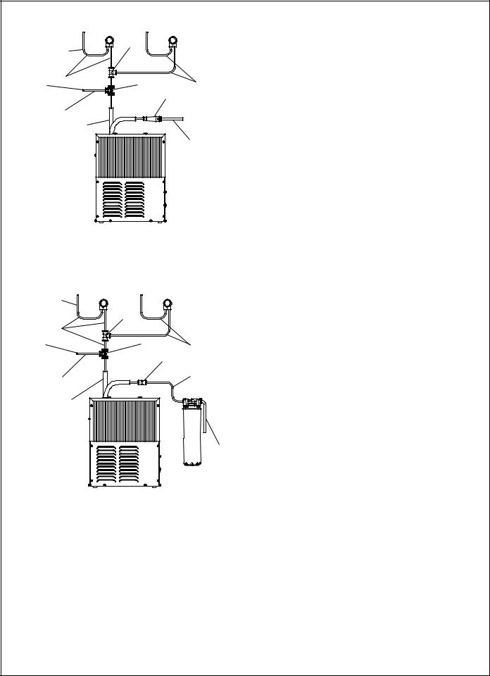
REQUIRED TOOLS AND MATERIALS
TO BUBBLER |
13 |
|
|
|
|
||
12 |
15 |
12 |
|
TO BOTTLE |
|||
|
|||
FILLER |
|
14 |
|
|
|
||
33 |
|
|
|
CHILLER |
|
|
|
OUTLET |
|
CHILLER |
|
|
|
||
|
|
INLET |
Figure 2 - EZWS-ERPB Tube Routing
These tables show special tools and/or additional materials
(not provided) which are necessary to complete installation of these units:
Special Tools |
|
|
|
|
|
Item |
Description |
Quantity |
|
NONE |
|
|
|
|
Additional Materials Not Included |
|
|
|
|
|
Item |
Description |
Quantity |
1 |
Unplated copper inlet pipe |
1 |
2 |
Service Stop/Shut-off Valve |
1 |
3 |
90° 1-1/4” Drain Line |
1 |
4 |
1-1/4” Tee Drain Line |
1 |
1.Make water supply connections. Install a shut-off valve and union connection to building water supply (valve and union not provided). Turn on water supply and flush the line thoroughly.
Caution: DO NOT SOLDER tubes inserted into the strainer or filter head as damage to the o-rings may result.
TO BUBBLER |
|
|
2. Install mounting frame (instructions supplied with mounting |
|
|
|
frame. |
12 |
13 |
|
3. (For LZWS-LRPBM28K) Install filter bracket on chiller (Fig 9), |
|
|
||
|
15 |
|
then install the filter head to the bracket, plumb from the filter |
TO BOTTLE |
12 |
outlet to the chiller inlet with ¼” poly tubing and ¼ x ¼ union, |
|
FILLER |
|
25 |
install filter. |
|
|
|
|
33 |
|
12 |
3a. (For EZWS-ERPBM28K) Install strainer on the input tube to |
|
the chiller (Fig 2). |
||
|
|
|
|
CHILLER |
|
|
4. Install chiller on shelf, install ¼ x ¼ x 3/8 Tee on chiller output |
OUTLET |
|
|
tube. Install supplied 4” poly tubing and armaflex to the outlet |
|
|
|
of the previously installed tee. Connect supplied ¼ x ¼ x ¼ |
|
|
|
tee to the 4” poly tubing. With the back panel standing close to |
|
|
WATER |
the frame, connect 3/8” poly tube to the bottle filler. |
|
|
Note: Building construction must allow for adequate air flow |
|
|
|
INLET |
|
|
|
|
on both sides, top & back of chiller. A minimum of 4” (102 mm) |
|
|
|
on both sides & top is required. See chiller installation for ad- |
|
|
|
ditional instructions. |
Figure 3 - LZWS-LRPB Tube Routing |
5. Hang main panel on mounting frame hanger. Make sure the |
||
|
|
|
|
|
|
|
power cord, reset switch wire & poly tube do not get pinched |
|
|
|
between the panel & mounting frame. Ensure the panel en |
|
|
|
gages at the top. Align fountain holes with mounting frame |
|
|
|
holes. |
|
|
|
6. Remove protective coating from main panel. |
|
|
|
7. Install fountains with (8) 5/16-18 HHMS, (8) 5/16-18 nuts & |
|
|
|
(4) support brackets (provided) (Fig 4). Connect the ¼” water |
|
|
|
lines from each fountain to the remaining openings on the tee |
|
|
|
at the remote chiller (cut lines to fit as needed), (Test fit refrig- |
|
|
|
erated panel to make sure there is a tight joint between it & the |
|
|
|
main panel before fully tightening mounting screws.) |
Page 3 |
0000001030 (Rev. F - 06/16) |
 Loading...