

Einhell BG-CS 235 E User manual [ml]
Art.-Nr.: 45.000.80 I.-Nr.: 11021
k
Originalbetriebsanleitung
Kettenschärfer
t
Original operating instructions
Chain Sharpener
p
Mode d’emploi d’origine
de lʼappareil à aiguiser les chaînes
C
Istruzioni per l’uso originali
Affilatore per catene
m
Manual de instrucciones original
Afilador de cadenas
U
Original-bruksanvisning
Kedjeslipmaskin
q
Alkuperäiskäyttöohje
Ketjunteroitin
Bf
Originalne upute za uporabu
naprave za oštrenje lanca
4
Originalna uputstva za upotrebu
Sprava za oštrenje lanca
Z
Orijinal Kullanma Talimatı
Zincir Bileme Aleti
BG-CS 235 E
2
3a
3b
4 5
1 2
3
A
13
10
A
B
A
A
A
B
C
4
5
2
12
11
10
8
7
9
13
6
1
3
6
C
C
8
9
10 11
7
7
1
2
5
1
3
1
4
6
2
7
1
4
14
15
1312
14
2
1
16

5
D
Inhaltsverzeichnis:
1. Sicherheitshinweise
2. Gerätebeschreibung
3. Bestimmungsgemäße Verwendung
4. Technische Daten
5. Vor Inbetriebnahme
6. Bedienung
7. Reinigung, Wartung und Ersatzteilbestellung
8. Entsorgung und Wiederverwertung

6
D
Achtung!
Beim Benutzen von Geräten müssen einige
Sicherheitsvorkehrungen eingehalten werden, um
Verletzungen und Schäden zu verhindern. Lesen Sie
diese Bedienungsanleitung / Sicherheitshinweise
deshalb sorgfältig durch. Bewahren Sie diese gut auf,
damit Ihnen die Informationen jederzeit zur
Verfügung stehen. Falls Sie das Gerät an andere
Personen übergeben sollten, händigen Sie diese
Bedienungsanleitung / Sicherheitshinweise bitte mit
aus. Wir übernehmen keine Haftung für Unfälle oder
Schäden, die durch Nichtbeachten dieser Anleitung
und den Sicherheitshinweisen entstehen.
1. Sicherheitshinweise
Die entsprechenden Sicherheitshinweise finden Sie
im beiliegenden Heftchen!
WARNUNG
Lesen Sie alle Sicherheitshinweise und
Anweisungen. Versäumnisse bei der Einhaltung der
Sicherheitshinweise und Anweisungen können
elektrischen Schlag, Brand und/oder schwere
Verletzungen verursachen zur Folge haben.
Bewahren Sie alle Sicherheitshinweise und
Anweisungen für die Zukunft auf.
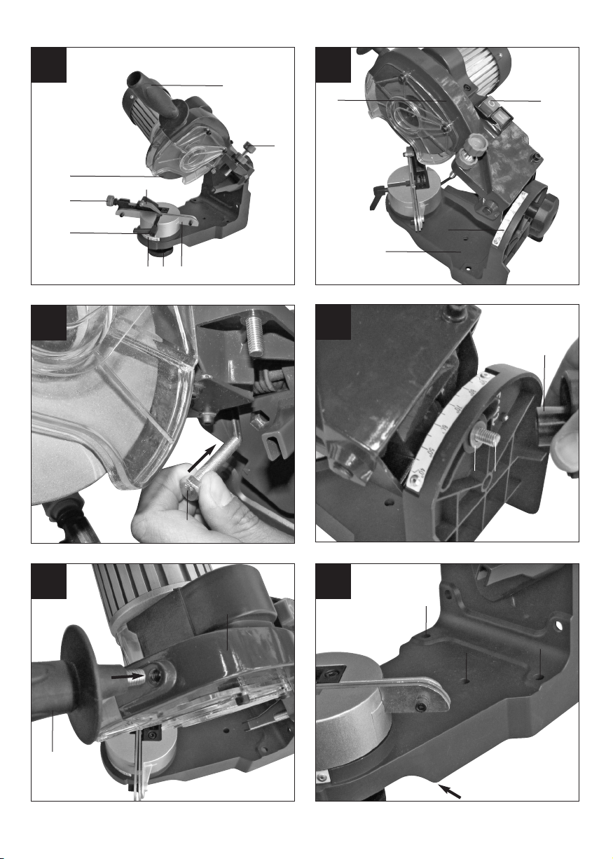
2. Gerätebeschreibung (Bild 1/2)
1. Kettenstopper
2. Einstellschraube Kettenstopper
3. Skala für Schleifwinkeleinstellung
4. Feststellschraube für Schleifwinkeleinstellung
5. Führungsschiene für Kette
6. Kettenfeststellschraube
7. Einstellschraube für Tiefenbegrenzung
8. Schleifscheibe
9. Ein-/Ausschalter
10. Schleifkopf
11. Untergestell
12. Dachschneidwinkel Skala
13. Handgriff
3. Lieferumfang
n Öffnen Sie die Verpackung und nehmen Sie das
Gerät vorsichtig aus der Verpackung.
n Entfernen Sie das Verpackungsmaterial sowie
Verpackungs-/ und Transportsicherungen (falls
vorhanden).
n Überprüfen Sie, ob der Lieferumfang vollständig
ist.
n Kontrollieren Sie das Gerät und die Zubehörteile
auf Transportschäden.
n Bewahren Sie die Verpackung nach Möglichkeit
bis zum Ablauf der Garantiezeit auf.
ACHTUNG
Gerät und Verpackungsmaterial sind kein
Kinderspielzeug! Kinder dürfen nicht mit
Kunststoffbeuteln, Folien und Kleinteilen spielen!
Es besteht Verschluckungs- und
Erstickungsgefahr!
n Originalbetriebsanleitung
n Sicherheitshinweise
4. Bestimmungsgemäße Verwendung
Der Kettenschärfer ist zum Schärfen von Sägeketten
geeignet.
Die Maschine darf nur nach ihrer Bestimmung
verwendet werden. Jede weitere darüber
hinausgehende Verwendung ist nicht
bestimmungsgemäß. Für daraus hervorgerufene
Schäden oder Verletzungen aller Art haftet der
Benutzer/Bediener und nicht der Hersteller.
Bitte beachten Sie, dass unsere Geräte
bestimmungsgemäß nicht für den gewerblichen,
handwerklichen oder industriellen Einsatz konstruiert
wurden. Wir übernehmen keine Gewährleistung,
wenn das Gerät in Gewerbe-, Handwerks- oder
Industriebetrieben sowie bei gleichzusetzenden
Tätigkeiten eingesetzt wird.
Die Maschine darf nur nach ihrer Bestimmung
verwendet werden! Trotz bestimmungsgemäßer
Verwendung können bestimmte Restrisikofaktoren
nicht vollständig ausgeräumt werden. Bedingt durch
die Konstruktion und den Aufbau der Maschine
können folgende Punkte auftreten:
n Berührung der Schleifscheibe im nicht
abgedeckten Bereich.
n Herausschleudern von Teilen aus beschädigten
Schleifscheiben.
n Herausschleudern von Werkstücken und
Werkstückteilen.
n Gehörschäden bei Nichtverwendung des nötigen
Gehörschutzes.

7
D
5. Technische Daten
Nennspannung: 230V~ 50 Hz
Leistungsaufnahme: 235 Watt
Leerlaufdrehzahl: 3000 min
-1
Einstellwinkel: 40º nach links und rechts
Schleifscheiben-Ø (innen): 22 mm
Schleifscheiben-Ø (aussen): max. 145 mm
Schleifscheibendicke: 3,2 mm
Schutzklasse: I
Gewicht: 5,8 kg
Geräusch und Vibration
Die Geräusch- und Vibrationswerte wurden entsprechend EN 61029 ermittelt.
Schalldruckpegel L
pA
68,3 dB(A)
Unsicherheit K
pA
3 dB
Schallleistungspegel L
WA
81,3 dB(A)
Unsicherheit K
WA
3 dB
Tragen Sie einen Gehörschutz.
Die Einwirkung von Lärm kann Gehörverlust
bewirken.
Schwingungsgesamtwerte (Vektorsumme dreier
Richtungen) ermittelt entsprechend EN 61029.
Schleifen
Schwingungsemissionswert ah = 3,675 m/s²
Unsicherheit K = 1,5 m/s²
Warnung!
Der angegebene Schwingungsemissionswert ist
nach einem genormten Prüfverfahren gemessen
worden und kann sich, abhängig von der Art und
Weise, in der das Elektrowerkzeug verwendet wird,
ändern und in Ausnahmefällen über dem
angegebenen Wert liegen.
Der angegebene Schwingungsemissionswert kann
zum Vergleich eines Elektrowerkzeuges mit einem
anderen verwendet werden.
Der angegebene Schwingungsemissionswert kann
auch zu einer einleitenden Einschätzung der
Beeinträchtigung verwendet werden.
Beschränken Sie die Geräuschentwicklung und
Vibration auf ein Minimum!
n Verwenden Sie nur einwandfreie Geräte.
n Warten und reinigen Sie das Gerät regelmäßig.
n Passen Sie Ihre Arbeitsweise dem Gerät an.
n Überlasten Sie das Gerät nicht.
n Lassen Sie das Gerät gegebenenfalls
überprüfen.
n Schalten Sie das Gerät aus, wenn es nicht
benutzt wird.
Restrisiken
Auch wenn Sie dieses Elektrowerkzeug vorschriftsmäßig bedienen, bleiben immer Restrisiken bestehen. Folgende Gefahren können im
Zusammenhang mit der Bauweise und Ausführung dieses Elektrowerkzeuges auftreten:
1. Lungenschäden, falls keine geeignete Staubschutzmaske getragen wird.
2. Gehörschäden, falls kein geeigneter Gehörschutz
getragen wird.
6. Vor Inbetriebnahme
Die gesamte Montage darf nur bei gezogenem
Netzstecker durchgeführt werden.
Montage des Schleifkopfs (Abb. 3a/3b)
Das Gerät besteht aus Schleifkopf (10) und
Untergestell (11) welche noch montiert werden
müssen.
Stecken Sie den Zentrierzapfen des Schleifkopfs in
die Öffnung des Untergestells. Nun die
Sechskantschraube (A) von vorne durch die Bohrung
im Schleifkopf und das Langloch im Untergestell
stecken und von hinten mit einer Beilagscheibe (B)
und der Sternschraube (C) fixieren.
Montage des Handgriffs (Abb. 4)
Schrauben Sie den Handgriff (13) in die dafür
vorgesehen Bohrung am Schleifkopf (10).
Tisch- Wandmontage(Abb. 5/6)
Das Gerät ist sowohl für die Tisch wie auch für die
Wandmontage geeignet.
Bei der Tischmontage muss die Kante (B) mit der
Tischkante abschließen, um das Gerät anschließend
mit den Bohrungen (A) zu fixieren.
Bei der Wandmontage müssen zur Fixierung die
Bohrungen (C) verwendet werden. Damit die
Dachschneidwinkelstellschraube auch weiterhin

8
D
bedient werden kann, sollten Distanzhülsen o.Ä.
verwendet werden.
Achten Sie bei der Wandmontage darauf, dass Sie
das Gerät nicht zu hoch anbringen, um nicht in
direkter Augenhöhe zu arbeiten.
7. Bedienung
Achtung! Vor jeder Einstellung am Gerät immer erst
das Gerät ausschalten und den Netzstecker ziehen.
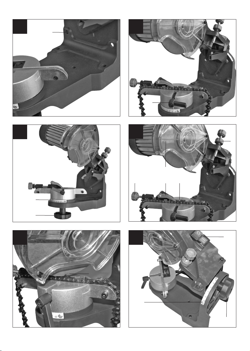
7.1 Zu schärfende Kette in die Führungsschiene
einlegen (Abb. 7)
Hierzu die Kettenfeststellschraube (1) lösen.
7.2 Schleifwinkel gemäß den Angaben ihrer Kette
einstellen (Abb. 8)
(Im Regelfall zwischen 30-35º)
n Feststellschraube für Schleifwinkeleinstellung (1)
lösen.
n Gewünschten Schleifwinkel anhand der Skala (2)
einstellen.
n Feststellschraube (1) wieder festziehen.
7.3 Dachwinkel gemäß den Angaben ihrer Kette
einstellen (Abb. 11) (Im Regelfall zwischen
50-60°)
n Feststellschraube (6) für Dachwinkeleinstellung
lösen.
n Gewünschten Dachwinkel anhand der Skala (7)
einstellen
n Feststellschraube (6) wieder festziehen
7.4 Kettenstopper einstellen (Abb. 9/10)
n Kettenstopper (1) auf Kette klappen.
n Kette rückwärts gegen den Kettenstopper (1)
ziehen bis dieser ein Schneideglied (2) stoppt.
Achtung! Hierbei muss darauf geachtet werden,
dass der Winkel des gestoppten
Schneidegliedes mit dem Schleifwinkel überein
stimmt. Wenn nicht, die Kette um ein
Schneideglied weiterziehen.
n Schleifkopf (4) nach unten klappen bis die
Schleifscheibe (5) das zu schleifende Kettenglied
(2) berührt. (Hierzu kann die Kette mit der
Einstellschraube des Kettenstoppers (3) etwas
nach vorne und zurück gestellt werden).
7.5 Tiefenbegrenzung einstellen (Abb. 9/10)
n Schleifkopf (4) nach unten klappen und
Schleiftiefe mit der Einstellschraube (7)
einstellen.
Achtung! Die Schleiftiefe soll so eingestellt
werden, dass die komplette Schneide des
Schneidegliedes geschärft wird.
7.6 Kette feststellen (Abb. 7)
n Kettenfeststellschraube (1) festziehen.
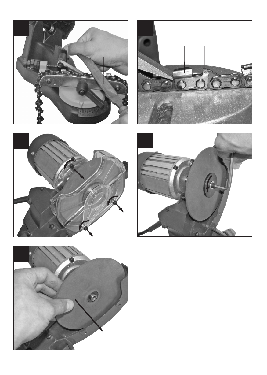
7.7 Glied schleifen (Abb. 10/11)
Achtung!
n Verwenden Sie das Gerät nur zum Schärfen von
Sägeketten. Schleifen oder schneiden Sie niemals andere Materialien.
n Klemmen Sie die Sägekette vor dem Schärfen in
der Führungsschiene fest. Dies verhindert ein
Verkanten der Schleifscheibe durch eine lose
Sägekette.
n Führen Sie die Schleifscheibe langsam an die
Sägekette. Ein zu schnelles und ruckartiges
Anfahren an die Sägekette kann dazu führen,
dass die Schleifscheibe beschädigt wird. Durch
Herausgeschleuderte Teile kann es zu Verletzungen kommen!
n Gerät mit Ein-/Ausschalter (1) einschalten.
n Schleifscheibe (5) mit Schleifkopf (4) vorsichtig
gegen das eingestellte Glied führen.
n Gerät mit Ein-/Ausschalter (1) ausschalten. Auf
diese Weise muss jedes zweite Glied der Kette
geschärft werden. Um zu wissen, wann jedes
zweite Glied der gesamten Kette geschärft ist,
empfiehlt sich das erste Glied zu markieren (z.B.
mit Kreide). Nachdem alle Schneideglieder der
einen Seite geschärft sind, muss der
Schleifwinkel auf die selbe Gradzahl der anderen
Seite der Winkeleinstellung eingestellt werden.
Anschließend können Sie beginnen, die Glieder
der anderen Seite zu schärfen.
7.8 Tiefenbegrenzerabstand einstellen
(Abb. 12/13)
Nachdem die Kette vollständig geschärft ist, muss
darauf geachtet werden, dass der
Tiefenbegrenzerabstand eingehalten wird (Die
Tiefenbegrenzer(1) müssen niedriger sein als die
Schneideglieder (2). Gegebenenfalls die
Tiefenbegrenzer (1) mit einer Feile (14) (nicht im
Lieferumfang enthalten) gemäß den Angaben Ihrer
Kette nachfeilen.
8. Reinigung, Wartung und
Ersatzteilbestellung
Ziehen Sie vor allen Reinigungsarbeiten den
Netzstecker.
8.1 Reinigung
n Halten Sie Schutzvorrichtungen, Luftschlitze und
Motorengehäuse so staub- und schmutzfrei wie
möglich. Reiben Sie das Gerät mit einem

sauberen Tuch ab oder blasen Sie es mit
Druckluft bei niedrigem Druck aus.
n Wir empfehlen, dass Sie das Gerät direkt nach
jeder Benutzung reinigen.
n Reinigen Sie das Gerät regelmäßig mit einem
feuchten Tuch und etwas Schmierseife.
Verwenden Sie keine Reinigungs- oder
Lösungsmittel; diese könnten die Kunststoffteile
des Gerätes angreifen. Achten Sie darauf, dass
kein Wasser in das Geräteinnere gelangen kann.
8.2 Wartung
Wechsel der Schleifscheibe
Achtung! Vor jeder Wartung am Gerät immer erst
das Gerät ausschalten und den Netzstecker ziehen.
1. Entfernen Sie die Schleifscheibe (Abb. 14-16).
2. Setzen Sie eine neue Schleifscheibe ein.
3. Der Zusammenbau erfolgt in umgekehrter
Reihenfolge.
Verwenden Sie keine verschlissenen, gebrochenen,
gesprungenen oder anderweitig beschädigten
Schleifscheiben. Verwenden Sie nur Original
Schleifscheiben.
8.3 Ersatzteilbestellung:
Bei der Ersatzteilbestellung sollten folgende
Angaben gemacht werden;
n Typ des Gerätes
n Artikelnummer des Gerätes
n Ident-Nummer des Gerätes
n Ersatzteilnummer des erforderlichen Ersatzteils
Aktuelle Preise und Infos finden Sie unter
www.isc-gmbh.info
9. Entsorgung und Wiederverwertung
Das Gerät befindet sich in einer Verpackung um
Transportschäden zu verhindern. Diese Verpackung
ist Rohstoff und ist somit wieder verwendbar oder
kann dem Rohstoffkreislauf zurückgeführt werden.
Das Gerät und dessen Zubehör bestehen aus
verschiedenen Materialien, wie z.B. Metall und
Kunststoffe. Führen Sie defekte Bauteile der
Sondermüllentsorgung zu. Fragen Sie im
Fachgeschäft oder in der Gemeindeverwaltung nach!
9
D

Table of contents:
1. Safety regulations
2. Layout
3. Intended use
4. Technical data
5. Before starting the equipment
6. Operation
7. Cleaning, maintenance and ordering of spare parts
8. Disposal and recycling
10
GB

Important!
When using the equipment, a few safety precautions
must be observed to avoid injuries and damage.
Please read the complete operating instructions and
safety regulations with due care. Keep this manual in
a safe place, so that the information is available at all
times. If you give the equipment to any other person,
hand over these operating instructions and safety
regulations as well. We cannot accept any liability for
damage or accidents which arise due to a failure to
follow these instructions and the safety instructions.
1. Safety regulations
The corresponding safety information can be found
in the enclosed booklet.
CAUTION!
Read all safety regulations and instructions.
Any errors made in following the safety regulations
and instructions may result in an electric shock, fire
and/or serious injury.
Keep all safety regulations and instructions in a
safe place for future use.
2. Layout (Fig. 1/2)
1. Chain stopper
2. Chain stopper setting screw
3. Scale for setting grinding angle
4. Locking screw for grinding angle setting
5. Chain bar for chain
6. Chain locking screw
7. Setting screw for limiting depth
8. Grinding wheel
9. ON/OFF switch
10. Grinding head
11. Base frame
12. Roof cutting angle scale
13. Handle
3. Items supplied
n Open the packaging and take out the equipment
with care.
n Remove the packaging material and any
packaging and/or transportation braces (if
available).
n Check to see if all items are supplied.
n Inspect the equipment and accessories for
transport damage.
n If possible, please keep the packaging until the
end of the guarantee period.
IMPORTANT
The equipment and packaging material are not
toys. Do not let children play with plastic bags,
foils or small parts. There is a danger of
swallowing or suffocating!
n Original operating instructions
n Safety instructions
4. Intended use
The chain sharpener is designed for sharpening saw
chains.
The machine is to be used only for its prescribed
purpose. Any other use is deemed to be a case of
misuse. The user / operator and not the
manufacturer will be liable for any damage or injuries
of any kind caused as a result of this.
Please note that our equipment has not been
designed for use in commercial, trade or industrial
applications. Our warranty will be voided if the
machine is used in commercial, trade or industrial
businesses or for equivalent purposes.
The machine must only be used for its intended
purpose! Even when the equipment is used as
prescribed it is still impossible to eliminate certain
residual risk factors. The following hazards may arise
in connection with the machine’s construction and
layout:
n Contact with the grinding wheel where it is not
covered.
n Catapulting of parts from damaged grinding
wheels.
n Catapulting of workpieces and parts of
workpieces from the machine.
n Damage to hearing if ear-muffs are not used as
necessary.
11
GB

5. Technical data
Rated voltage: 230V ~ 50Hz
Power input: 235 watts
Idle speed: 3000min
-1
Adjustment angle: 40º to the left and right
Grinding wheel Ø (inside): 22 mm
Grinding wheel Ø (outside): max. 145 mm
Grinding wheel thickness: 3.2 mm
Protection class: I
Weight: 5.8 kg
Sound and vibration
Sound and vibration values were measured in
accordance with EN 61029.
LpAsound pressure level 68,3 dB(A)
KpAuncertainty 3 dB
LWAsound power level 81,3 dB(A)
KWAuncertainty 3 dB
Wear ear-muffs.
The impact of noise can cause damage to hearing.
Total vibration values (vector sum of three directions)
determined in accordance with EN 61029.
Grinding
Vibration emission value a
h
= 3,675 m/s
2
K uncertainty = 1,5 m/s
2
Warning!
The specified vibration value was established in
accordance with a standardized testing method. It
may change according to how the electric equipment
is used and may exceed the specified value in
exceptional circumstances.
The specified vibration value can be used to compare
the equipment with other electric power tools.
The specified vibration value can be used for initial
assessment of a harmful effect.
Keep the noise emissions and vibrations to a
minimum.
앬 Only use appliances which are in perfect working
order.
앬 Service and clean the appliance regularly.
앬 Adapt your working style to suit the appliance.
앬 Do not overload the appliance.
앬 Have the appliance serviced whenever
necessary.
앬 Switch the appliance off when it is not in use.
앬 Wear protective gloves.
Residual risks
Even if you use this electric power tool in
accordance with instructions, certain residual
risks cannot be rules out. The following hazards
may arise in connection with the equipment’s
construction and layout:
1. Lung damage if no suitable protective dust mask
is used.
2. Damage to hearing if no suitable ear protection is
used.
6. Before starting the equipment
The entire assembly process may only be carried out
after the power plug has been pulled.
Fitting the grinding head (Fig. 3a/3b)
The equipment consists of the grinding head (10)
and the base frame (11) which must still be fitted.
Insert the centering pin of the grinding head into the
opening of the base frame. Now insert the hexagon
head bolt (A) from the front through the hole in the
grinding head and the oval hole in the base frame
and secure on the back with a washer (B) and a star
screw (C).
Fitting the handle (Fig. 4)
Screw the handle (13) into the intended hole on the
grinding head (10).
Mounting on a table or wall (Fig. 5/6)
The equipment is designed for both table top
installation and wall mounting.
When installing the equipment on a table top, first
make sure that the edge of the equipment is flush
with the edge of the table, then secure the
equipment with the holes (A).
When mounting the equipment on the wall, use the
holes (C) to secure the equipment. Spacer sleeves
or the like should be used so that the roof cutting
angle set screw remains accessible.
When mounting the equipment on a wall, make sure
that it is not fitted too high so as to avoid working at
eye level.
12
GB

7. Operation
Important! Always switch the appliance off and
unplug the power plug before making any
adjustments.
7.1 Insert the chain that is to be sharpened into
the chain bar (Fig. 7)
앬 To do this, loosen the chain locking screw (1)
7.2 Set the grinding angle according to the
specifications for your chain (Fig. 8) (normally
between 30-35º)
앬 Slacken the locking screw for setting the grinding
angle (1)
앬 Set the desired grinding angle using the scale (2)
앬 Tighten the locking screw (1) again
7.3 Set the roof angle according to the
specifications for your chain (Fig. 11) (normally
between 50-60°)
앬 Undo the locking screw (6) for the roof angle
adjustment.
앬 Set the desired roof angle using the scale (7).
앬 Re-tighten the locking screw (6).
7.4 Set the chain stopper (Fig. 9/10)
앬 Fold the chain stopper (1) onto the chain
앬 Pull the chain backwards against the chain
stopper (1) until the latter stops a cutting link (2)
Important! You must make sure that the angle
of the stopped cutting link coincides with the
grinding angle. If it does not, pull the chain one
link further.
앬 Fold the grinding head (4) down until the grinding
wheel (5) is touching the chain link (2) that is to
be ground. (To do so, you can move the chain
back and forth a little using the setting screw of
the chain stopper (3)
7.5 Set the depth limit (Fig. 9/10)
앬 Fold the grinding head (4) down and set the
grinding depth using the setting screw (7)
Important! The grinding depth should be set so
that the full cutting edge of the cutting link is
sharpened.
7.6 Lock the chain (Fig. 7)
앬 Tighten the chain locking screw (1)
7.7 Grind the link (Fig. 10/11)
Important!
앬 Only use the equipment for sharpening saw
chains. Never grind or cut other materials.
앬 Before sharpening the saw chain clamp it into the
chain bar. This will prevent jamming of the
grinding wheel caused by a loose saw chain.
앬 Slowly guide the grinding wheel to the saw blade.
If the grinding wheel approaches the saw chain
too quickly or jerkily, this may cause damage to
the grinding wheel. Injuries may result from
catapulting parts!
앬 Switch the appliance on at the ON/OFF switch
(1)
앬 Carefully bring the grinding wheel (5) with
grinding head (4) so that it is against the set link
앬 Switch the appliance off at the ON/OFF switch
(1) Every second link in the chain must be
sharpened in this way. To know when every
second link in the entire chain has been
sharpened, mark the first link (e.g. with chalk).
Once all cutting links on one side have been
sharpened, the grinding angle must be set to the
same number of degrees on the other side.
You can then begin to sharpen the links of the
other side.
7.8 Set the depth limiter spacing (Fig. 12/13)
Once the chain has been fully sharpened, you must
make sure that the depth limiter spacing is kept (the
depth limiters (1) must be lower than the cutting links
(2). You may need to file the depth limiters (1) to the
specifications for your chain using a file (14) (not
included in delivery).
8. Cleaning, maintenance and ordering
of spare parts
Always pull out the mains power plug before starting
any cleaning work.
8.1 Cleaning
Keep all safety devices, air vents and the motor
housing free of dirt and dust as far as possible. Wipe
the equipment with a clean cloth or blow it with
compressed air at low pressure.
We recommend that you clean the tool immediately
after you use it.
Clean the equipment regularly with a moist cloth and
some soft soap. Do not use cleaning agents or
solvents; these may be aggressive to the toolʼs
plastic parts. Ensure that no water can get into the
interior of the tool.
8.2 Changing the grinding wheel
Important! Always switch the appliance off and
unplug the power plug before carrying out any
maintenance.
1. Remove the grinding wheel (Figs. 14-16)
2. Fit a new grinding wheel
13
GB

3. Assemble in reverse order
Do not use grinding wheels that are worn, broken,
cracked or otherwise damaged.
Use only genuine grinding wheels.
8.3 Ordering replacement parts
Please provide the following information on all orders
for spare parts:
앬 Model/type of tool
앬 Article number of the tool
앬 ID number of the tool
앬 Number of the required spare part
For our latest prices and information please go to
www.isc-gmbh.info
9. Disposal and recycling
The unit is supplied in packaging to prevent its being
damaged in transit. This packaging is raw material
and can therefore be reused or can be returned to
the raw material system.
The unit and its accessories are made of various
types of material, such as metal and plastic.
Defective components must be disposed of as
special waste. Ask your dealer or your local council.
14
GB

Sommaire :
1. Consignes de sécurité
2. Description de lʼappareil
3. Utilisation conforme à lʼaffectation
4. Données techniques
5. Avant la mise en service
6. Commande
7. Nettoyage, maintenance et commande de pièces de rechange
8. Mise au rebut et recyclage
15
F

Attention !
Lors de lʼutilisation dʼappareils, il faut respecter
certaines mesures de sécurité afin dʼéviter des
blessures et dommages. Veuillez donc lire
attentivement ce mode dʼemploi/ces consignes de
sécurité. Veillez à le conserver en bon état pour
pouvoir accéder aux informations à tout moment. Si
lʼappareil doit être remis à dʼautres personnes, veillez
à leur remettre aussi ce mode dʼemploi/ces
consignes de sécurité. Nous déclinons toute
responsabilité pour les accidents et dommages dus
au non-respect de ce mode dʼemploi et des
consignes de sécurité.
1. Consignes de sécurité:
Vous trouverez les consignes de sécurité
correspondantes dans le cahier en annexe.
AVERTISSEMENT !
Veuillez lire toutes les consignes de sécurité et
instructions.
Tout non-respect des consignes de sécurité et
instructions peut provoquer une décharge électrique,
un incendie et/ou des blessures graves.
Conservez toutes les consignes de sécurité et
instructions pour une consultation ultérieure.
2. Description de lʼappareil (fig. 1/2)
1. étrangloir de chaîne
2. vis de réglage de lʼétrangloir de chaîne
3. échelle graduée pour le réglage de lʼangle
dʼaffûtage
4. vis dʼarrêt pour le réglage de lʼangle dʼaffûtage
5. rail de guidage de la chaîne
6. vis dʼarrêt de la chaîne
7. vis de réglage de la limitation de profondeur
8. meule
9. interrupteur Marche/Arrêt
10. tête de polissage
11. Support
12. Echelle graduée dʼangle de coupe
13. Poignée
3. Volume de livraison
n Ouvrez l’emballage et prenez l’appareil en le
sortant avec précaution de l’emballage.
n Retirez le matériel d’emballage tout comme les
sécurités d’emballage et de transport (s’il y en a).
n Vérifiez si la livraison est bien complète.
n Contrôlez si l’appareil et ses accessoires ne sont
pas endommagés par le transport.
n Conservez l’emballage autant que possible
jusqu’à la fin de la période de garantie.
ATTENTION
L’appareil et le matériel d’emballage ne sont pas
des jouets ! Il est interdit de laisser des enfants
jouer avec des sacs et des films en plastique et
avec des pièces de petite taille. Ils risquent de
les avaler et de s’étouffer !
n Mode d’emploi d’origine
n Consignes de sécurité
4. Utilisation conforme à lʼaffectation
Lʼappareil à aiguiser les chaînes sert à lʼaffûtage de
chaînes de scie.
La machine doit exclusivement être employée
conformément à son affectation. Chaque utilisation
allant au-delà de cette affectation est considérée
comme non conforme. Pour les dommages en
résultant ou les blessures de tout genre, le
producteur décline toute responsabilité et
lʼopérateur/lʼexploitant est responsable.
Veillez au fait que nos appareils, conformément à
leur affectation, nʼont pas été construits, pour être
utilisés dans un environnement professionnel,
industriel ou artisanal. Nous déclinons toute
responsabilité si lʼappareil est utilisé
professionnellement, artisanalement ou dans des
sociétés industrielles, tout comme pour toute activité
équivalente.
La machine doit être exclusivement utilisée
conformément à son affectation ! Malgré l’emploi
conforme à l’affectation, certains facteurs de risques
résiduels ne peuvent être complètement supprimés.
Selon la construction et la conception de la machine,
les risques suivants peuvent apparaître :
n Contact avec le disque abrasif à l’endroit non
recouvert.
n Projection de pièces provenant de disques
abrasifs endommagés.
n Projection de pièces à usiner et de parties de la
pièce à usiner.
n Lésions de l’ouïe si vous n’employez pas la
protection de l’ouïe nécessaire.
16
F

5. Caractéristiques techniques
Tension nominale : 230V ~ 50Hz
Puissance absorbée : 235 Watts
Vitesse de rotation de marche à vide : 3000 t/min
Angle de mise au point : 40º à gauche et à droite
Ø de meule (intérieur) : 22 mm
Ø de meule (extérieur) : max. 145 mm
Epaisseur de meule : 3,2 mm
à isolement de protection : I
Poids : 5,8 kg
Bruit et vibration
Les valeurs de bruit et de vibration ont été
déterminées conformément à la norme EN 61029.
Niveau de pression acoustique L
pA
68,3 dB(A)
Imprécision K
pA
3 dB
Niveau de puissance acoustique L
WA
81,3 dB(A)
Imprécision K
WA
3 dB
Portez une protection acoustique.
Lʼexposition au bruit peut entraîner la perte de lʼouïe.
Les valeurs totales des vibrations (somme des
vecteurs de trois directions) ont été déterminées
conformément à EN 61029.
Affûtage
Valeur dʼémission des vibrations a
h
= 3,675 m/s
2
Imprécision K = 1,5 m/s
2
Avertissement !
La valeur d’émission de vibration a été mesurée selon
une méthode d’essai normée et peut être modifiée,
en fonction du type d’emploi de l’outil électrique ; elle
peut dans certains cas exceptionnels être supérieure
à la valeur indiquée.
La valeur d’émission de vibration indiquée peut être
utilisée pour comparer un outil électrique à un autre.
La valeur d’émission de vibration indiquée peut
également être utilisée pour estimer l’altération au
début.
Limitez le niveau sonore et les vibrations à un
minimum !
앬 Utilisez exclusivement des appareils en excellent
état.
앬 Entretenez et nettoyez l’appareil régulièrement.
앬 Adaptez votre façon de travailler à l’appareil.
앬 Ne surchargez pas l’appareil.
앬 Faites contrôler l’appareil le cas échéant.
앬 Mettez l’appareil hors circuit lorsque vous ne
l’utilisez pas.
앬 Portez des gants.
Risques résiduels
Même en utilisant cet outil électrique
conformément aux prescriptions, il reste
toujours des risques résiduels. Les dangers
suivants peuvent apparaître en rapport avec la
construction et le modèle de cet outil électrique :
1. Lésions des poumons si aucun masque antipoussière adéquat n’est porté.
2. Déficience auditive si aucun casque anti-bruit
approprié n’est porté.
6. Avant la mise en service
Lʼensemble du montage doit uniquement être réalisé
lorsque la fiche secteur est débranchée.
Montage de la tête de meulage (fig. 3a/3b)
Lʼappareil se compose de la tête de meulage (10) et
du support (11), qui doit encore être monté.
Enfichez les broches de centrage de la tête de
meulage dans lʼouverture du support. Enfichez à
présent la vis à tête hexagonale (A) de lʼavant dans
le perçage de la tête de meulage et le trou oblong du
support et fixez-la de lʼarrière avec une rondelle (B)
et la vis-étoile (C).
Montage de la poignée (fig. 4)
Vissez la poignée (13) dans le perçage prévu à cet
effet sur la tête de meule (10).
Montage mural - sur table (fig. 5/6)
Lʼappareil convient aussi bien au montage sur table
quʼau montage mural.
Dans le cas du montage sur table, lʼarête (B) doit se
terminer au niveau de lʼarête de la table pour fixer
ensuite lʼappareil avec les perçages (A).
Dans le cas du montage mural, il faut utiliser les
perçages (C) pour la fixation. Pour pouvoir continuer
à commander la vis de réglage de lʼangle de coupe,
il faut utiliser des douilles dʼécartement ou similaire.
Veillez lors du montage mural, à ne pas monter
lʼappareil trop haut, pour ne pas travailler
directement à hauteur des yeux.
17
F

7. Commande
Attention ! Avant tout réglage de lʼappareil, mettez
toujours lʼappareil hors circuit et débrancher la prise
secteur.
7.1 Introduisez la chaîne à affûter dans le rail de
guidage (fig. 7)
앬 dévissez la vis dʼarrêt de la chaîne (1) dans ce
but
7.2 Réglez lʼangle dʼaffûtage conformément aux
indications de votre chaîne (fig. 8) (en règle
générale entre 30 et 35º)
앬 desserrez la vis dʼarrêt pour le réglage de lʼangle
dʼaffûtage (1)
앬 réglez lʼangle dʼaffûtage désiré à lʼaide de
échelle graduée (2)
앬 resserrez la vis dʼarrêt (1) à fond.
7.3 Réglez lʼangle conformément aux indications
de votre chaîne (fig. 11) (en règle générale entre
50 et 60º)
앬 Desserrez la vis de fixation (6) pour le réglage de
lʼangle.
앬 Réglez lʼangle désiré à lʼaide de lʼéchelle
graduée (7)
앬 Resserrez la vis de fixation (6) à fond
7.4 Régler lʼétrangloir de chaîne (fig. 9/10)
앬 rabattez lʼétrangloir de chaîne (1) sur la chaîne
앬 tirez la chaîne en arrière contre lʼétrangloir de
chaîne (1) jusquʼà ce quʼil arrête un maillon
coupant (2).
Attention ! Il faut veiller ce faisant à ce que
lʼangle du maillon arrêté corresponde à celui
dʼaffûtage. Sinon, tirez la chaîne encore dʼun
maillon coupant.
앬 Rabattez la tête de polissage (4) vers le bas
jusquʼà ce que la meule (5) touche le maillon
chaîne à affûter (2). (pour ce faire, on peut faire
avancer ou reculer la chaîne à lʼaide de la vis de
réglage de lʼétrangloir de chaîne)
7.5 Régler la limitation de profondeur (fig. 9/10)
앬 Rabattez la tête de polissage (4) vers le bas et
réglez la profondeur dʼaffûtage avec la vis de
réglage (7)
Attention ! La profondeur dʼaffûtage doit être
réglée de manière que la lame complète du
maillon coupant soit aiguisée.
7.6 Arrêter la chaîne (fig. 7)
앬 Serrez la vis dʼarrêt de la chaîne (1) à fond
7.7 Aiguisez le maillon (fig. 10/11)
Attention !
앬 Utilisez l’appareil uniquement pour l’affûtage des
chaines de scie. Ne jamais affûter ou couper
d’autres matériaux.
앬 Avant l’affûtage, coincer la chaîne de scie dans le
rail de guidage. Cela évite que le disque abrasif
ne se bloque du fait d’une chaîne de scie mobile.
앬 Guidez lentement le disque abrasif le long de la
chaîne de scie. Un passage trop rapide et
saccadé sur la chaîne de scie peut entraîner un
endommagement du disque abrasif. Risque de
blessures dues à la projection de pièces !
앬 Mettez lʼappareil en circuit avec lʼinterrupteur
Marche / Arrêt (1)
앬 Introduisez la meule (5) avec la tête de polissage
(4) précautionneusement contre le maillon régler
앬 Mettez lʼappareil en circuit avec lʼinterrupteur
Marche / Arrêt (1). Chaque deuxième maillon de
la chaîne doit être affûté de la sorte. Pour savoir
à quel moment chaque deuxième maillon de la
chaîne entière est affûté, il est conseillé de
marquer le premier maillon (p. ex. avec de la
craie). Une fois tous les maillons de coupe
affûtés dʼun côté, il faut régler lʼangle dʼaffûtage
sur le même angle de lʼautre côté du réglage
dʼangle. Ensuite, vous pouvez commencer à
affûter les maillons de lʼautre côté.
7.8 Réglez la distance de limiteur de profondeur
(fig. 12/13)
Une fois la chaîne complètement affûtée, il faut veiller à maintenir la distance de limiteur de profondeur
(les limiteurs de profondeur (1) doivent être plus bas
que les maillons de coupe (2)). Réaffûtez le cas
échéant les limiteurs de profondeur (1) avec une lime
(14) (non comprise dans la livraison) conformément
aux indications de votre chaîne.
8. Nettoyage, maintenance et
commande de pièces de rechange
Retirez la fiche de contact avant tous travaux de
nettoyage
8.1 Nettoyage
Maintenez les dispositifs de protection, les fentes à
air et le carter de moteur aussi propres (sans
poussière) que possible. Frottez lʼappareil avec un
chiffon propre ou soufflez dessus avec de lʼair
comprimé à basse pression.
Nous recommandons de nettoyer lʼappareil
directement après chaque utilisation.
Nettoyez lʼappareil régulièrement à lʼaide dʼun chiffon
18
F

humide et un peu de savon. Nʼutilisez aucun produit
de nettoyage ni détergeant ; ils pourraient
endommager les pièces en matières plastiques de
lʼappareil. Veillez à ce quʼaucune eau nʼentre à
lʼintérieur de lʼappareil.
8.2 Changement de meule
Attention ! Avant toute maintenance de lʼappareil,
mettez toujours lʼappareil hors circuit et débrancher
la prise secteur
1. Supprimez la meule (fig. 14-16)
2. Introduisez une nouvelle meule.
3. Le montage sʼeffectue dans lʼordre inverse
Nʼutilisez aucune meule usée, cassée, fendue ou
détériorée de toute autre manière.
Utilisez exclusivement des meules dʼorigine.
8.3 Commande de pièces de rechange
Indiquer ce qui suit pour toute commande de pièces
de rechange :
앬 Type de lʼappareil
앬 Numéro dʼarticle de lʼappareil
앬 Numéro dʼidentification de lʼappareil :
앬 Numéro de pièce de rechange de la pièce de
rechange nécessaire
Vous trouverez les prix et informations actuelles à
lʼadresse www.isc-gmbh.info
9. Mise au rebut et recyclage
Lʼappareil se trouve dans un emballage permettant
dʼéviter les dommages dus au transport. Cet
emballage est une matière première et peut donc
être réutilisé ultérieurement ou être réintroduit dans
le circuit des matières premières.
Lʼappareil et ses accessoires sont en matériaux
divers, comme par ex. des métaux et matières
plastiques. Eliminez les composants défectueux
dans les systèmes dʼélimination des déchets
spéciaux. Renseignez-vous dans un commerce
spécialisé ou auprès de lʼadministration de votre
commune !
19
F

Indice
1. Avvertenze di sicurezza
2. Descrizione dellʼapparecchio
3. Utilizzo proprio
4. Caratteristiche tecniche
5. Prima della messa in esercizio
6. Uso
7. Pulizia, manutenzione e ordinazione dei pezzi di ricambio
8. Smaltimento e riciclaggio
20
I

Attenzione!
Nellʼusare gli apparecchi si devono rispettare diverse
avvertenze di sicurezza per evitare lesioni e danni.
Quindi leggete attentamente queste istruzioni per
lʼuso/le avvertenze di sicurezza. Conservate bene le
informazioni per averle a disposizione in qualsiasi
momento. Se date lʼapparecchio ad altre persone,
consegnate queste istruzioni per lʼuso/le avvertenze
di sicurezza insieme allʼapparecchio. Non ci
assumiamo alcuna responsabilità per incidenti o
danni causati dal mancato rispetto di queste
istruzioni e delle avvertenze di sicurezza.
1. Avvertenze sulla sicurezza
Le relative avvertenze di sicurezza si trovano
nellʼopuscolo allegato.
AVVERTIMENTO!
Leggete tutte le avvertenze di sicurezza e le
istruzioni.
Dimenticanze nel rispetto delle avvertenze di
sicurezza e delle istruzioni possono causare scosse
elettriche, incendi e/o gravi lesioni.
Conservate tutte le avvertenze e le istruzioni per
eventuali necessità future.
2. Descrizione dellʼapparecchio
(Fig. 1/2)
1. Blocco catena
2. Vite di regolazione blocco catena
3. Scala per regolazione dellʼangolo di affilatura
4. Vite di serraggio per regolazione dellʼangolo di
affilatura
5. Guida per catena
6. Vite di serraggio della catena
7. Vite di regolazione per limitazione di profondità
8. Disco abrasivo
9. Interruttore ON/OFF
10. Testa portamola
11. Basamento
12. Scala angolo di affilatura
13. Impugnatura
3. Elementi forniti
n Aprite l’imballaggio e togliete con cautela
l’apparecchio dalla confezione.
n Togliete il materiale d’imballaggio e anche i fermi
di trasporto / imballo (se presenti).
n Controllate che siano presenti tutti gli elementi
forniti.
n Verificate che l’apparecchio e gli accessori non
presentino danni dovuti al trasporto.
n Se possibile, conservate l’imballaggio fino alla
scadenza della garanzia.
ATTENZIONE
L’apparecchio e il materiale d’imballaggio non
sono giocattoli! I bambini non devono giocare
con sacchetti di plastica, film e piccoli pezzi!
Sussiste pericolo di ingerimento e
soffocamento!
n Istruzioni per l’uso originali
n Avvertenze di sicurezza
4. Utilizzo proprio
Lʼaffilatore è adatto allʼaffilatura di catene per seghe.
Lʼapparecchio deve venire usato solamente per lo
scopo a cui è destinato. Ogni altro tipo di uso che
esuli da quello previsto non è un uso conforme.
Lʼutilizzatore/lʼoperatore, e non il costruttore, è
responsabile dei danni e delle lesioni di ogni tipo che
ne risultino.
Tenete presente che i nostri apparecchi non sono
stati costruiti per lʼimpiego professionale, artigianale
o industriale. Non ci assumiamo alcuna garanzia
quando lʼapparecchio viene usato in imprese
commerciali, artigianali o industriali, o in attività
equivalenti.
L’elettroutensile deve essere usato solamente per lo
scopo a cui è destinato! Anche se l’apparecchio viene
usato in modo corretto non si possono escludere
completamente determinati fattori di rischio residuo.
Visto il funzionamento e la struttura dell’elettroutensile
si possono presentare i seguenti punti:
n Contatto con il disco abrasivo nella zona non
coperta.
n Parti di dischi abrasivi danneggiati scagliate
all’ingiro.
n Pezzi da lavorare e loro frammenti scagliati
all’ingiro.
n Danni all’udito se non si indossano le cuffie
antirumore necessarie.
21
I

5. Caratteristiche tecniche
Tensione nominale: 230V ~ 50Hz
Potenza assorbita: 235 Watt
Numero di giri a vuoto: 3000min
-1
Angolo di regolazione: 40º a destra e a sinistra
Ø dischi abrasivi (interno): 22 mm
Ø dischi abrasivi (esterno): max. 145 mm
Spessore dischi abrasivi: 3,2 mm
Isolamento di protezione: I
Peso: 5,8 kg
Rumore e vibrazioni
I valori del rumore e delle vibrazioni sono stati rilevati
secondo la norma EN 61029.
Livello di pressione acustica L
pA
68,3 dB (A)
Incertezza K
pA
3 dB
Livello di potenza acustica L
WA
81,3 dB (A)
Incertezza K
WA
3 dB
Portate cuffie antirumore.
Lʼeffetto del rumore può causare la perdita dellʼudito.
Valori complessivi delle vibrazioni (somma vettoriale
delle tre direzioni) rilevati secondo la norma EN
61029.
Smerigliatura
Valore emissione vibrazioni a
h
= 3,675 m/s
2
Incertezza K = 1,5 m/s
2
Avvertimento!
Il valore di emissione di vibrazioni indicato è stato
misurato secondo un metodo di prova normalizzato e
può variare a seconda del modo in cui l’elettroutensile
viene utilizzato e, in casi eccezionali, può essere
superiore al valore riportato.
Il valore di emissione di vibrazioni indicato può essere
usato per il confronto tra elettroutensili di marchi
diversi.
Il valore di emissione di vibrazioni può essere
utilizzato anche per una valutazione preliminare dei
rischi.
Limitate al minimo lo sviluppo di rumore e le
vibrazioni!
앬 Utilizzate soltanto apparecchi in perfetto stato.
앬 Eseguite regolarmente la manutenzione e la
pulizia dell’apparecchio.
앬 Adattate il vostro modo di lavorare
all’apparecchio.
앬 Non sovraccaricate l’apparecchio.
앬 Fate eventualmente controllare l’apparecchio.
앬 Spegnete l’apparecchio se non lo utilizzate.
앬 Indossate i guanti.
Rischi residui
Anche se questo elettroutensile viene utilizzato
secondo le norme, continuano a sussistere
rischi residui. In relazione alla struttura e al
funzionamento di questo elettroutensile
potrebbero presentarsi i seguenti pericoli:
1. Danni all’apparato respiratorio nel caso in cui non
venga indossata una maschera antipolvere
adeguata.
2. Danni all’udito nel caso in cui non vengano
indossate cuffie antirumore adeguate.
6. Prima della messa in esercizio
Tutto il montaggio deve essere eseguito solo con la
spina staccata dalla presa di corrente.
Montaggio della testa portamola (Fig. 3a/3b)
Lʼapparecchio è composto di testa portamola (10) e
basamento (11) che sono ancora da montare.
Inserite il perno di centraggio della testa portamola
nellʼapertura del basamento. Ora inserite la vite a
testa esagonale (A) dal davanti attraverso il foro
nella testa portamola e lʼasola nel basamento e
fissatela da dietro con una rosetta (B) e la vite a
stella (C).
Montaggio dellʼimpugnatura (Fig. 4)
Avvitate lʼimpugnatura (13) nellʼapposito foro nella
testa portamola (10).
Montaggio su banco/a parete (Fig. 5/6)
Lʼapparecchio è adatto sia per il montaggio su banco
che a parete.
In caso di montaggio su banco il bordo (B) deve
essere a livello con il bordo del banco, per fissare poi
lʼapparecchio con i fori (A).
In caso di montaggio al parete i fori (C) devono
essere usati per il fissaggio. Per poter usare la vite di
regolazione dellʼangolo di affilatura anche in futuro, si
22
I
 Loading...