

Introduction
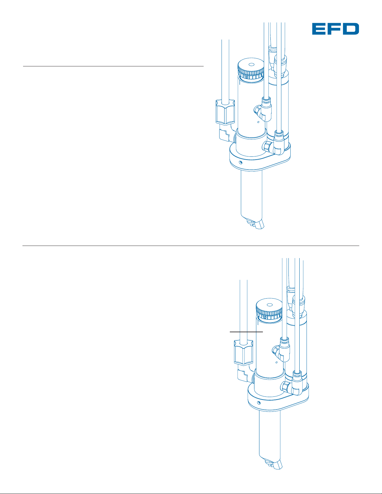
The 782RA is a precision, air-actuated spray valve that
produces a narrow radial output ideal for coating the interiors of cylinders. LVLP (low volume low pressure) air is
used to atomize the fluid, while a precision air motor
drives a rotating air cap that produces the radial output.
The 782RA valve has a 5.6 cm (2.2”) extended rotor air
cap that will reach inside cylinders with a minimum inner
diameter of 2.5 cm (1.0”). The valve is simple to use and
will operate many millions of cycles without maintenance.
782RA Spray Valve
INSTALLATION GUIDE
Rotor
Fluid inlet
fitting
Air cylinder
body
Fluid supply line
USA: 800-556-3484 or +1-401-434-1680
Europe: 0800 585733 or +44 (0) 1582 666334
Asia: +86 (21) 5854 2345
technical@efd-inc.com www.efd-inc.com
Electronic pdf files of EFD®manuals are also available at
www.efd-inc.com/manuals.html.
®
A NORDSON COMPANY
0
5
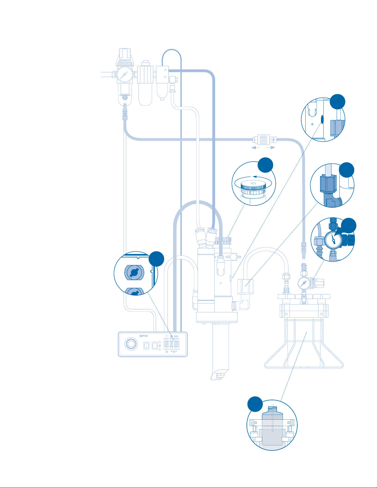
Installation
1. Mount valve using the 1/4-28
UNF tapped hole on the air
cylinder body.
2. Connect the fluid feed hose to
the reservoir outlet and the
valve-inlet port using the
appropriate fittings (supplied).
3. Connect the 4 mm diameter
air hoses from the valve to the
controller. The white goes to
the “A” port and the black
goes to the “B” port.
4. Connect the 6 mm diameter
air hoses from the motor to
the air preparation assembly.
The white connects to the
control valve. The black
connects to the motor speed
control fitting.
5. Fill the fluid reservoir. After
filling, secure the cover and
connect the reservoir air pressure regulator to the air tee
using the flexible air line (supplied). Attach the black male
quick-connect on the air line
to the reservoir regulator and
then attach the white quickconnect to the air tee. To
pressurize the system, slide
the shut-off valve on the air
line toward the fluid reservoir.
6. Set the reservoir pressure reg-
ulator according to fluid viscosity, to low for thin fluids 1
to 3 psi (0.07 to 0.2 bar) and
higher for thick fluids.
7. Set the needle stroke control
at one turn open. This is a
starting point. Final setting will
be determined by the desired
flow rate.
Prior to installing this valve,
please read the associated
reservoir and valve controller
operating instructions to
become familiar with the operation of all components of the
dispensing system.
Output A
Output B
3
5
1
7
2
6
Air Preparation Assembly: See pages 6 – 7,
ValveMate 7060RA Controller Operating Manual.
To pressurize
To exhaust
®
VALVEMATE
A NORDSON COMPANY
7060RA
M
M
M

How the Valve Operates
ValveMate Concept
The ValveMate 7060RA provides
easy adjustment of valve output
for maximum end-user convenience and efficiency. Valve opentime is the primary control of
deposit size. The 7060RA puts
push-button adjustment of valve
open time where it needs to be –
at the valve.
The controller incorporates
unique microprocessor circuitry
to provide exact time control and
interact with the host computer.
A built-in air pressure regulator
provides low volume low pressure nozzle air to ensure high
open
closed
➃➃
➂➂
➁➁
➀➀
Input-air pressure at 70 psi (4.8 bar)
acts on a piston
➀➀
that retracts the
needle
➁➁
from its nozzle seat ➂➂, permitting fluid flow from the nozzle ➃➃. At
the same time, atomizing air from the
ValveMate™7060RA controller is turned
on and flows from the rotor air tube
➄➄
across the fluid nozzle at a 70° angle.
This atomizing air creates a pressure
drop around the nozzle, causing fluid
to atomize into fine droplets and follow
the direction of the atomizing air flow.
The rotor, spinning at approximately
2500 rpm, causes the radial output to
sweep around and evenly coat the
inner circumference of the cylinder.
When the timed actuating air
from the ValveMate 7060RA
controller shuts off, the piston
spring moves the needle onto
the nozzle seat and shuts-off
fluid flow. An adjustable
atomizing air delay ensures
that all fluid is atomized after
the valve closes, eliminating
post-deposit spatter.
transfer efficiency without
overspray.
Deposit size can be programmed by pressing the
PROGRAM button in the
SETUP mode. This affords
an easy starting point for
selecting deposit size.
Note: The EFD Ultra
®
TT 325
and 525 XYZ automated dispensing systems have integrated ValveMate controllers
for operating all EFD dispense
valves.
➄➄
www.efd-inc.com technical@efd-inc.com USA 800-556-3484 Europe +44 (0) 1582 666334 Asia +86 (21) 5854 2345
®
A NORDSON COMPANY
7060RA
Rear Panel
air input
power input
air output to valve
I/O interface terminal strip
air exhaust
atomizing air output
connector for
optional foot pedal
VALVEMATE
M
M
M
Control Pad
cycle / test
time override
time / pressure
and psi / bar toggle
program
time set

Specifications
General
Size: 174.5 mm length x 68.6 mm diameter (6.87” x 2.70”)
Weight: 408.2 grams (14.4 oz)
Air consumption: <0.3 SCFM at 80 psi (5.4 bar)
Air cylinder body: Hard-coated aluminum
Fluid body: Hard-coated aluminum
Piston: Type 303 stainless steel
Piston return spring: Stainless steel
Needle and nozzle: Stainless steel
Rotor: Hard-coated aluminum
Fluid inlet hole: 1/8 NPT female
Air pressure required: 70 psi (4.8 bar)
Mounting: 1/4-28 UNF tapped hole
Spray Coverage
782RA distance from nozzle center to inside diameter of
cylinder wall.
14˚
Spray coverage shown 1/2 actual size
Nozzle distance to inside diameter
For consistent dispense valve operation and easy adjustment
of valve output, EFD recommends using the ValveMate
7060RA controller on all automatic, semi-automatic and
benchtop applications.
The EFD Ultra TT Series positioning systems incorporate
dispensing control into the main system.
Contact the EFD Dispense Valve Systems Group for details.
For EFD sales and service in over 30 countries,
contact EFD or go to www.efd-inc.com/contact
EFD, Inc.
East Providence, RI USA
800-556-3484; +1-401-434-1680 (outside the USA)
info@efd-inc.com www.efd-inc.com
EFD International Inc.
Dunstable, Bedfordshire, UK
0800 585733 or +44 (0) 1582 666334
Ireland 00800 8272 9444
europe@efd-inc.com www.efd-inc.com
EFD, Inc., Asia
China: +86 (21) 5854 2345
china@efd-inc.com www.efd-inc.com/cn
Singapore: +65 6896 9630 sin-mal@efd-inc.com
©2006 Nordson Corporation 782-INSTALL-01 v062606
®
A NORDSON COMPANY
25.4 mm (1.0”)
4.3 mm (0.17”)
76.2 mm (3.0”)
12.7 mm (0.5”)
152.4 mm
(6.0”)
25.4 mm
(1.0”)
 Loading...