

Page 1
Introduction
The 781S Series precision low volume low pressure
(LVLP) liquid spray valves are designed for high transfer
efficiency without overspray or airborne mist and provide
consistent coating of low to medium viscosity fluids.
781S Series valves are simple to use and will operate
many millions of cycles without maintenance. Spray valve
cleaning is accomplished by purging with the appropriate
solvent.
The 781S air cylinder body and fluid body are hard-coated
aluminum. The 781S-SS valve model uses stainless steel
throughout.
781S Series Spray Valve
INSTALLATION GUIDE
Electronic pdf files of EFD®manuals are also available at
www.efd-inc.com/manuals.html.
USA: 800-556-3484 or +1-401-434-1680
Europe: 0800 585733 or +44 (0) 1582 666334
Asia: +86 (21) 5854 2345
technical@efd-inc.com www.efd-inc.com
®
A NORDSON COMPANY
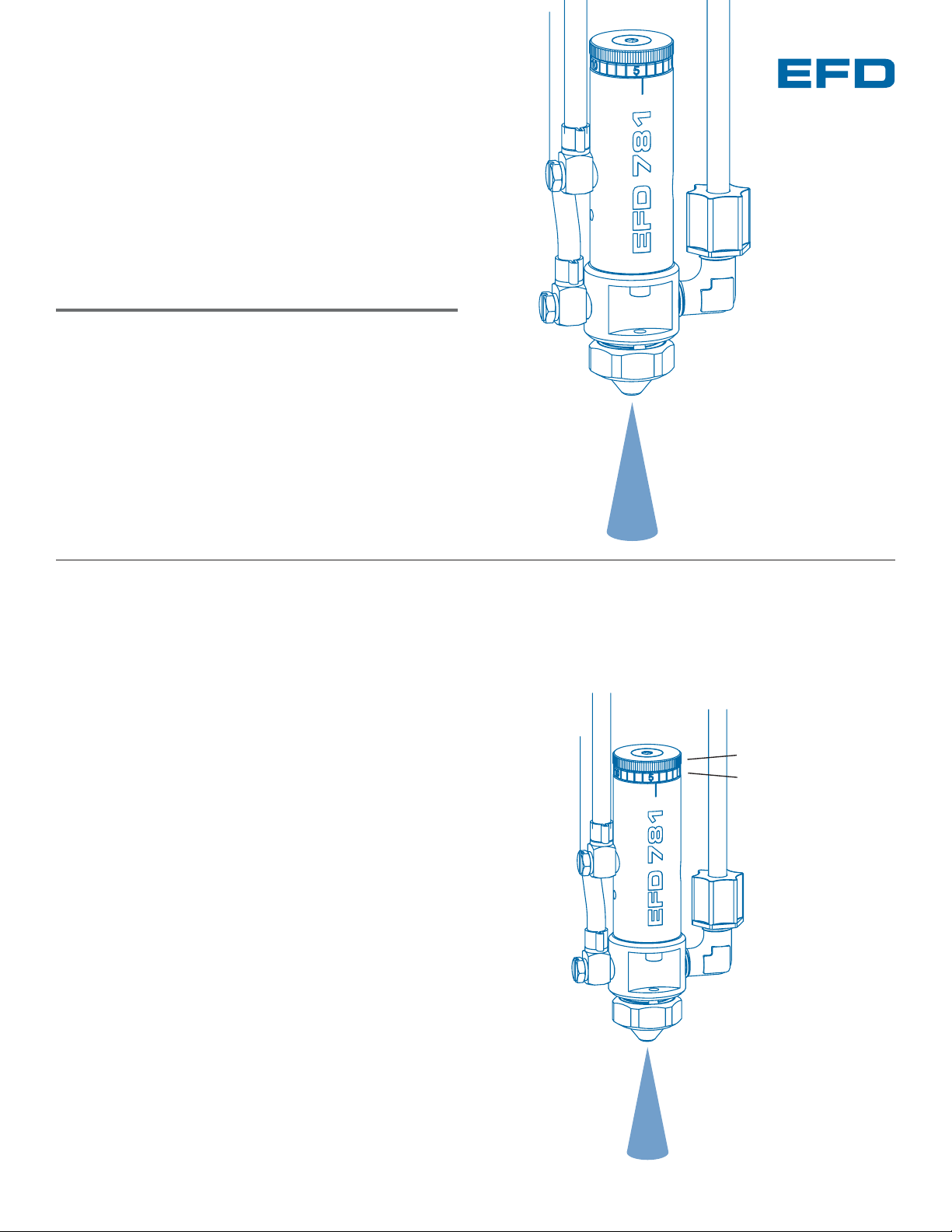
Nozzle
air hose
Valve control
air hose
Fluid
supply line
Needle stroke
control knob
Stroke reference ring
Inlet fitting
LVLP spray valve
Page 2
Installation
1. Mount valve with an EFD universal
valve mount (#7002VM) or other
fixture.
2. Connect the fluid supply line
to the fluid inlet port and to the
reservoir.
3. Connect the control air hose
(labeled “A”) and the nozzle air
hose (labeled “B”) to corresponding
outputs on ValveMate
™
controller
(or other pneumatic switch).
4. Fill reservoir by pouring fluid directly
into tank liner or manufacturer’s
bottle placed inside reservoir.
Secure cover prior to setting
pressure.
5. Set reservoir pressure to low for
thin fluids and higher for thick fluids.
6. Turn off nozzle air at the controller
regulator. Open the needle stroke
control one full turn. Place a cup
under the nozzle and actuate the
valve until fluid lines are free of air.
7.
Using the needle stroke control knob
on the 781S valve, set the fluid flow
rate to one or two drops per second.
Check flow rate by actuating the
controller in the time override mode.
Make valve stroke adjustments
when the controller is off.
8.
Set the nozzle air pressure on the
ValveMate 7040 controller to 10 psi
(.7 bar) and actuate the controller.
The valve will produce a fine spray.
To change fluid flow, use the needle
stroke control knob and/or reservoir
pressure.
To change nozzle air, use the
nozzle air pressure regulator. Higher
pressures will provide finer spray.
Output A
Output B
Prior to installing this valve, please
read the associated reservoir and
valve controller operating instructions to become familiar with the
operation of all components of the
dispensing system.
1
5
4
3
Open
Close
7
Note: The area of spray coverage is determined by the distance
between the spray valve nozzle and the work surface. Refer to the
charts on the back page to determine this distance.
2
VALVEMATE
7040
6
8
To exhaust
To pressurize
VALVEMATE
7040
5
20
0
Page 3

www.efd-inc.com technical@efd-inc.com USA 800-556-3484 Europe +44 (0) 1582 666334 Asia +86 (21) 5854 2345
How the Valve Operates
Input air pressure at 70 psi (4.8 bar) retracts the needle
➀➀
from its nozzle seat,
➁➁
allowing liquid to flow from the nozzle.
At the same time, nozzle air is turned on and flows from an
annulus ➂➂around the liquid nozzle. This adjustable nozzle
air creates a pressure drop around the nozzle causing the
liquid to atomize into fine droplets.
The amount sprayed is controlled by the valve open time,
reservoir pressure and needle stroke. Area of coverage is
determined by the nozzle size and the distance between
the nozzle and work surface.
To calibrate or document the dispensing process, use the
stroke control reference. To calibrate, turn the calibrating
adjustment (located in the end of the stroke adjustment
knob) out two full turns. Close the stroke adjustment knob
fully until it bottoms against the air cylinder body. Turn the
adjustment until it stops, calibrating the valve to zero stroke.
*
ValveMate Concept
The ValveMate 7040 provides easy adjustment of valve output
for maximum end-user convenience and efficiency. Valve
open time is the primary control of deposit. The 7040 puts
push-button adjustment of valve open time where it needs to
be – near the valve.
Microprocessor circuitry provides exact control of the spray
valve to achieve exceptional spray pattern definition. The
ValveMate 7040 also incorporates a built-in adjustable delay
in nozzle air shut-off to assure clean cut-off.
Deposit size can be programmed by using the TEACH function.
This affords an easy starting point for selecting deposit size.
Note: The EFD Ultra®TT 325 and 525 XYZ automated
dispensing systems have integrated ValveMate controllers for
operating all EFD dispense valves.
*
The 781S valve can be ordered in a tamper-resist configuration
to limit unauthorized adjustment. Specify part #781S-TR or
#781S-SS-TR.
The primary control of deposit size is the valve open time.
➀➀
➂➂
➁➁
➀➀
➂➂
➁➁
781 Series Fluid Flow
closed open
Nozzle Air Gauge
Rear Panel
air input
power input
(voltage selector)
air output to valve
nozzle air
I/O connector
connector for
optional foot pedal
Nozzle Air
Pressure Regulator
VALVEMATE
7040
Control Pad
set time
timer bypass
test cycle
move decimal
reset
TEACH program
set cutoff air delay
Page 4

Specifications
781S and MM781-SYS
Weight: 235.3 grams (8.29 oz)
Fluid body: Hard-coated aluminum
Air cylinder body: Hard-coated aluminum
781S-SS
Weight: 405.3 grams (14.29 oz)
Fluid body: Type 303 stainless steel
Air cylinder body: Type 303 stainless steel
General
Size: 104.6 mm length x 26.9 mm diameter
(4.12” x 1.06”)
Air cap: Type 303 stainless steel
Piston: Type 303 stainless steel
Needle and nozzle: Type 303 stainless steel
Free flow orifice: 1.17 mm (0.046”); 0.71 mm (0.028”);
or 0.36 mm (0.014”)
Needle packings: Teflon
®
Fluid inlet thread: 1/8 NPT female
Mounting: (1) 1/4-28 UNF tapped hole
Air pressure required: 70 to 90 psi (4.8 to 6.2 bar)
Maximum input fluid pressure: 300 psi (20.7 bar)
Maximum operating temperature: 102ºC (215ºF)
Operating frequency: Exceeds 400 cycles/minute
Note: All stainless steel valve parts are passivated.
Spray Patterns
Nozzle Distance from the Work Surface:
Nozzle Distance from the Work Surface:
Fan Pattern Spray Area Coverage
Round Pattern Spray Area Coverage
25.4 mm 50.8 mm 76.2 mm 152.4 mm
Nozzles 1” 2” 3” 6”
#7857-46SS
Standard
1.17 mm 6.35 mm 12.70 mm 19.05 mm 38.10 mm
(0.046”) 0.25” 0.50” 0.75” 1.50”
#7857-46WA-SS
Wide-angle
1.17 mm 19.05 mm 38.10 mm 50.80mm
Not
(0.046”) 0.75” 1.50” 2.00”
Recommended
#7857-28SS
0.71 mm 5.08 mm 10.16 mm 15.24 mm 30.48 mm
(0.028”) 0.20” 0.40” 0.60” 1.20”
#7857-14SS
0.36 mm 4.32 mm 8.64 mm 12.70 mm 25.40 mm
(0.014”) 0.17” 0.34” 0.50” 1.00”
25.4 mm 50.8 mm 76.2 mm 152.4 mm
Nozzles 1” 2” 3” 6”
#7857F-46SS
(1.17 mm) 25.40 mm 38.10 mm 50.80 mm 82.55 mm
0.046" 1.00" 1.50" 2.00" 3.25"
#7857-46WF-SS
(1.17 mm) 38.1 mm 63.5 mm 82.55 mm 165.1 mm
0.046" 1.50" 2.50" 3.25" 6.50"
#7857F-28SS
(0.71 mm) 10.16 mm 20.32 mm 30.48 mm 60.96 mm
0.028" 0.40" 0.80" 1.20" 2.40"
#7857F-14SS
(0.36 mm) 8.63 mm 17.27 mm 25.4 mm 50.8 mm
0.014" 0.34" 0.68" 1.00" 2.00"
For consistent dispense valve operation and easy adjustment
of valve output, EFD recommends using the ValveMate 7040
controller on all automatic, semi-automatic and benchtop
applications.
The EFD Ultra TT Series positioning systems incorporate
dispensing control into the main system.
Contact the EFD Dispense Valve Systems Group for details.
For EFD sales and service in over 30 countries,
contact EFD or go to www.efd-inc.com/contact
EFD, Inc.
East Providence, RI USA
800-556-3484; +1-401-434-1680 (outside the USA)
info@efd-inc.com www.efd-inc.com
EFD International Inc.
Dunstable, Bedfordshire, UK
0800 585733 or +44 (0) 1582 666334
Ireland 00800 8272 9444
europe@efd-inc.com www.efd-inc.com
EFD, Inc., Asia
China: +86 (21) 5854 2345
china@efd-inc.com www.efd-inc.com/cn
Singapore: +65 6896 9630 sin-mal@efd-inc.com
Teflon is a registered trademark of DuPont.
©2006 Nordson Corporation 781S-INSTALL-01 v062606
Round
Fan
Side view of
fan air cap
®
A NORDSON COMPANY
 Loading...