

US: 888-333-0311
UK: 0800 585733
Mexico: 001-800-556-3484
780S Series Spray Valves
VALVEMATE
™
7040 Controller
Operating Manual
®
A NORDSON COMPANY

If you require any assistance or have specific questions, please contact us.
US: 888-333-0311
Telephone: 401-434-1680
Fax: 401-431-0237
E-mail: technical@efd-inc.com
Mexico: 001-800-556-3484
UK: 0800 585733
EFD Inc.
977 Waterman Avenue, East Providence, RI 02914-1342 USA
Sales and service of EFD Dispense Valve Systems is available
through EFD authorized distributors in over 30 countries.
Please contact EFD U.S.A. for specific names and addresses.

Contents
Introduction..................................................................2
Specifications ..............................................................3
How The Valve and Controller Operate ......................4
Controller Operating Features ....................................5
Typical Setup ..............................................................6
Setup ........................................................................7-8
Adjusting the Spray......................................................9
Programming Nozzle Air Delay ..................................10
Spray Patterns ..........................................................11
Troubleshooting Guide ........................................12-13
Valve Maintenance................................................14-16
780S Exploded View..................................................17
Input / Output Connections..................................18-19
Connecting More than One 7040 Controller..............20
7040 Schematic and Replacement Parts ..................21
Warranty ....................................................................22
Meets CSA and CE standards.
780/7040-MAN ©2003 EFD Inc.
This manual is for the express and sole use of EFD valve purchasers and users,
and no portion of this manual may be reproduced in any form.
EFD and VALVEMATE are trademarks of EFD Inc.
Teflon is a registered trademark of DuPont.

2 / Introduction
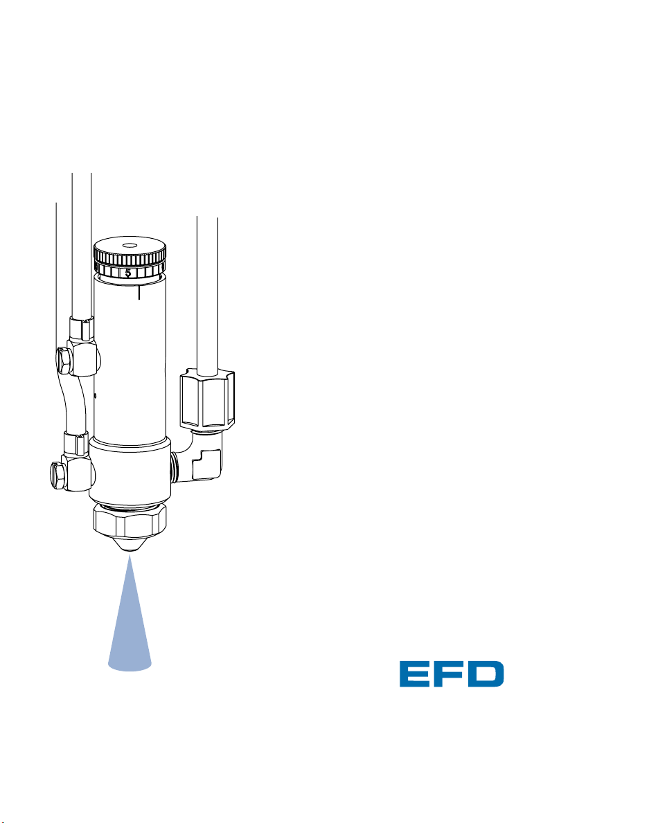
Introduction
The 780S Series precision Low Volume Low Pressure
(LVLP) liquid spray valves are manufactured to the
highest quality standards. The VALVEMATE™7040
controller features an adjustable nozzle air flow
regulator and a microprocessor-based timed air pressure output for controlling the ON time of the 780S
valve.
This equipment is produced to very close tolerances to
ensure proper and reliable operation. Each valve and
controller has been thoroughly tested prior to shipping.
The 780S and VALVEMATE™7040 are simple to use
and will operate many millions of cycles without maintenance. Spray valve cleaning is accomplished by
purging with the appropriate solvent.
To obtain the maximum performance from this fine
equipment, please read through these instructions
carefully.

Note: All stainless steel valve parts are passivated.
Specifications and technical details are subject to
engineering changes without prior notification.
VALVEMATE™7040 Controller
Cabinet size: W 7.5" x D 5.6" x H 2.7"
(W 19 x D 14 x H 7 cm)
Net weight: 3.1 lb (1.4 kg)
Air input required: 70 psi (4.8 bar) minimum
Input voltage: 100/120/220 VAC selectable
Power required: 50/60 Hz 14/12VA
Foot pedal voltage: 5 VDC
Time range: .001 to 99.9 seconds
Timing control: Microprocessor-based CMOS logic
Time cycle repeat 0.00005 seconds
Time reset: Less than 20 milliseconds
Initiation: Dry contact closure or 5 to 24 VDC signal
Output pressure:
Actuating air 70 psi (4.8 bar)
Nozzle air 1 to 30 psi (0.07 to 2.07 bar)
Cycle rate: Exceeds 600 per minute
Cycle end feedback circuit: N.C. solid-state switch
5 to 24 VDC, 250 mA maximum load
Specifications
780S Spray Valve
Size: 4.120" x 1.060" dia. (104.6 x 26.9 mm)
Weight: 780S: 8.3 oz (235 g)
780S-SS: 14.3 oz (405 g)
Air cylinder body: 780S-SS: Type 303 stainless steel
780S: Hard-coated aluminum
Fluid chamber: 780S-SS: Type 303 stainless steel
780S: Hard-coated aluminum
Piston: Type 303 stainless steel
Piston return spring: Type 303 stainless steel
Needle and Nozzle: Type 303 stainless steel
Air cap: 780S-SS: Type 303 stainless steel
780S: Plated brass
Needle packings: Teflon
®
Packing spring: Stainless steel
Liquid inlet hole: 1/8 NPT female
Mounting: 1/4-28 UNF tapped hole
Operating frequency: Exceeds 400 per minute
Air pressure required: 70 psi (4.8 bar)
Minimum mounting center distance: 1.067" (27.1 mm)
Standard nozzle diameter: 0.046" (1.17 mm)
Optional nozzle sizes: 0.028" (0.71 mm)
0.014" (0.36 mm)
Spray patterns: Round (standard)
Fan (optional)
3 / Specifications
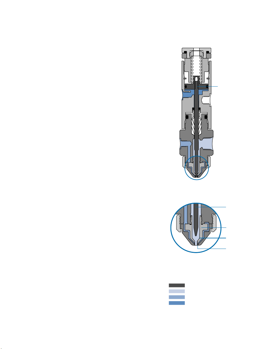
How The Valve and Controller Operate
open position
The 780S is a normally closed, air actuated needle
type spray valve that uses a Low Volume Low
Pressure (LVLP) design for high transfer efficiency
without overspray or airborne mist.
Air pressure from the VALVEMATE™7040 controller at
70 psi (4.8 bar) acts on a piston➀that retracts the needle ➁ from its nozzle seat ➂ and allows liquid to flow
from the nozzle ➃. At the same time, nozzle air, also
from the 7040, is turned on and flows from an annulus
➄ around the liquid nozzle.
This adjustable nozzle air creates a pressure drop
around the nozzle, causing the liquid to atomize into
fine droplets.
When the timed actuating air from the 7040 shuts off,
the piston spring moves the needle onto the nozzle
seat, shutting off liquid flow. A preset nozzle air delay
ensures that no liquid remains on the nozzle after the
valve closes, eliminating after-deposit spatter.
The amount sprayed is controlled by the valve open
time, reservoir pressure and needle stroke. Area of
coverage is determined by the nozzle size and the distance between the 780S nozzle and the work surface.
closed position
4 / How The Valve and Controller Operate
Piston and needle
➀
Nozzle seat
➂
Needle
➁
Annulus
➄
Nozzle
➃
Piston and needle assembly
Fluid
Nozzle air
Operating air
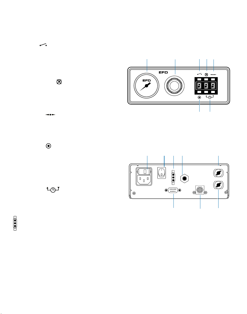
1. Cycle
Press to initiate one complete dispense
cycle. Press this button again to interrupt a
timed cycle. Press and hold while in the time
override mode for continuous cycle. Release
to stop.
2. Time override
Press to override time control. Display will
show (---). While in this mode, dispensing is
manual using the cycle button, voltage initiate source or foot pedal (optional, #2015A).
3. Decimal
Press to move decimal and change time
range maximums from .999 to 9.99 or 99.9.
Decimal does not appear in the display while
in the .999 second range.
4. Program
Press to clear display to zeros. Display
flashes bright/dim while in program mode.
Press cycle button and hold until proper
amount is sprayed. Total spray time will be
displayed. Press program button again to
lock in spray time.
5. Time set
Press to change time setting up or down.
Press and release to advance one digit at a
time, or press and hold to scroll quickly.
6. Foot pedal connector
If using the optional foot pedal, press the
pedal momentarily to initiate the 7040 controller. To interrupt a timed dispense cycle,
press the pedal again.
Controller Operating Features
5 / Controller Operating Features
Nozzle
air regulator
Nozzle
air gauge
12
3
5
Power
switch
6
Air input
quick-coupler
70 psi (4.8 bar)
minimum input
pressure
Valve
operating
air output
(white)
Nozzle
air output
(black)
Output A
Output B
Air
exhaust
9 pin D connector
I/O interface
(see page 18 for details)
Input power
cord receptacle
(see page 7
for details)
120
4
VALVEMATE
7040
Caution: Always depressurize the reservoir before
opening. To do this, slide the shutoff valve on the
air line away from the reservoir. If using an EFD
tank, open the pressure relief valve as well. Before
opening the reservoir, check the pressure gauge to
verify that pressure is zero (0).
On all EFD cartridge reservoirs, the unique threaded design provides fail-safe air pressure release
during cap removal.
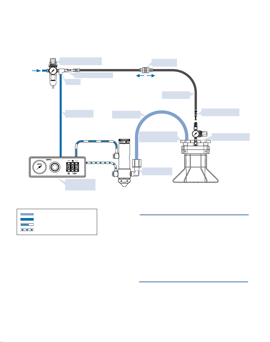
Typical Setup
6 / Typical Setup
5 micron filter regulator
Fluid feed hose
#7543BP (installed)
for 1/4" OD tube
Pressurized reservoir
with air regulator
ValveMate™
7040 Controller
Plant air
70 psi (4.8 bar)
minimum
Material
Constant air
Pulsed air for valve operation
Pulsed nozzle air
VALVEMATE
7040
20
0
5
Control air line
Air tee
White quick connect
Flexible air line
Fluid inlet fitting
Pressure relief valve
Black quick-connect
Shutoff valve
To pressurizeTo exhaust
#7610BP (included)
for 3/8" OD tube

Voltage value
Spare fuse
Cartridge window
(check voltage indicated)
supply.
4. Install the air tee with barb fitting
(#1116) in the output of the filter regulator
and, using the screw clamp provided, install
the black hose with coupling to the barb fitting. The quick-connect on the air tee is
used to provide air pressure to the air pressure regulator on EFD fluid reservoirs. This
connection will be made in step 10.
5. Remove the cap plug from the air input
of the VALVEMATE™7040 and attach the
input air hose coupling onto the controller
air input fitting. Adjust the filter regulator to
70 psi (4.8 bar).
6. Mount the 780S valve with an EFD
Universal Valve Mount (#7002VM) or other
appropriate fixture.
7. Connect the fluid feed hose to the
reservoir outlet and the 780S inlet port
using appropriate fittings shown on the
Setup Schematic, page 6.
8. The 780S is equipped with nozzle and
control air hoses with male quick-connects
that plug into the VALVEMATE™7040. Plug
the control air hose labeled “A” into output
“A” (white) on the rear panel of the 7040
and the nozzle air hose labeled “B” into
output “B” (black), also located on the 7040
rear panel.
9. Check that all connections are tight and
attached to the proper output.
10. Fill the fluid reservoir. After filling,
secure the cover and connect the reservoir air pressure regulator to the air tee
by using the connecting hose (#2310S).
First, attach the black male quick-connect on the connecting hose to the
reservoir regulator and then attach the
other end with the white male quickconnect to the air tee.
Setup
Input Power
1. View cartridge window in power cord
receptacle to ensure that fuse voltage
value matches your input voltage.
If it does not match, remove the fuse cartridge. Then remove the fuse holder
from the cartridge, rotate the holder and
position the correct voltage to show
through the cartridge window. Replace
the cartridge into the power cord receptacle and ensure that both sides snap
securely into position.
Connect the power cord.
Initiate Connection
2. The 7040 is normally operated by applying a 5 to 24 VDC pulse to terminal pins
1 and 2, or providing contact closure
across pins 5 and 7. Alternatively, a foot
pedal may be ordered (#2015A) and
plugged into the connector located on
the rear panel. Detailed electrical
schematic and diagrams are shown on
pages 18 and 19.
3. Connect the VALVEMATE
™
7040 to plant
air by first installing the EFD five-micron
filter regulator (#2000F755) to your air
7 / Setup
220
120
100
NEXT

Tamper Resist Option
Note: The area of spray coverage is determined by
the distance between the spray valve nozzle and
the work surface. Refer to the chart on page 11 to
determine this distance.
11. Set the reservoir pressure regulator
according to the fluid viscosity. For
example, low viscosity fluids require only
1 to 3 psi (0.07 to 0.2 bar). Higher pressures are required for more viscous fluids.
12. Close needle stroke control knob, fully
(clockwise), then set at one turn open.
This is a starting point only. Final setting
will be determined by the desired
flow rate.
13. Check the nozzle air gauge. If not at
zero, turn the regulator knob clockwise
to turn off the nozzle air.
Note: Regulator knobs on EFD tanks and conrollers
have a push-to-lock, pull-to-unlock feature.
14. Place a container under the valve
to collect the fluid during this setup
procedure.
15. Turn on the power switch. Press the
time override button to place the 7040
into the manual mode (---).
16. Press and hold the cycle button or
optional foot pedal. Continue to hold
until the fluid lines and the valve are
primed and purged of all air.
The 780S valve can be ordered in a tamper resist configuration to limit unauthorized
adjustment.
In the TR configuration, stroke adjustment
can only be made when a special stroke
control knob is inserted into the stroke
mechanism.
A tamper resist stroke kit can also be
ordered as a retrofit for existing valves.
Part # Description
780S-TR Tamper resist spray valve
.046
7544SS Tamper resist stroke kit
Stroke Control Reference
8 / Setup
The Stroke Control Reference allows you
to calibrate the stroke control setting or
document the dispensing process.
To calibrate, close the stroke control knob
all the way. Loosen the set screw and turn
the reference ring so the zero on the ring
aligns with one of the two reference marks
on the valve body. When the set screw is
tightened, the valve is calibrated.
Existing 780S Series valves are easily
upgraded with the Stroke Control
Reference Kit (#780SR-KIT).
Set Screw
Reference
Mark
Stroke
Reference
Ring
Stroke
Control
Knob
Removable
stroke control
knob
Stroke
mechanism

9 / Adjusting the Spray
Adjusting the Spray
Check to be sure steps 11 through 16 under Setup have
been completed, then proceed to adjust the spray.
1. Using the needle stroke control knob ➀ on the
780S valve, set the fluid flow rate to one or two
drops per second. Check flow rate by actuating
the controller in the time override mode. Make
valve stroke adjustments when the controller is off.
2. Set the nozzle air pressure on the VALVEMATE
™
7040 controller to 10 psi and actuate the controller.
The valve will produce a fine spray.
To change fluid flow, use the needle stroke control
knob ➀.
To change nozzle air, use the nozzle air pressure
regulator ➁. Higher pressures will provide finer spray.
To Make Timed Deposits
Return to the time control by pressing the time override
button ➂. The display should show the time setting.
Adjust the deposit time to 0.5 seconds by using the
time set ➃ and decimal ➄ buttons. (See page 5 for
operation of these buttons.)
Press the cycle button ➅. The 7040 will open the valve
for 0.5 seconds. Adjust time up or down and test
deposits until desired output is obtained.
Optimal results will be obtained with the proper combination of time setting, needle stroke control knob, and
reservoir and nozzle air pressure.
➀
VALVEMATE
7040
➁
➂➃➄
➅

10 / Programming Nozzle Air Delay
Programming Nozzle Air Delay
The nozzle air time delay can be changed from the
factory setting of 0.24 seconds to fine-tune the shutoff
characteristics of the 780S spray valve.
When making small deposits of low viscosity fluid, it
may be necessary to shorten the time delay to eliminate
a hollow center in the deposit.
To change the time delay:
1. Turn the power switch off.
2. Press and hold the time override button while turning
power switch on.
3. The display will read "SEL" (select). Release the time
override button.
4. Press either the up or down time set buttons once
and release. The current nozzle air delay setting will
be displayed. (The delay is preset to 0.24 seconds
for all new controllers.)
5. Press the up or down time set button again to
program the new nozzle air delay. (Available range
is 0.00 to 2.50 seconds.)
6. To exit the nozzle air delay program mode, momentarily press the time override button. The spray time
setting will be displayed.
Note: The VALVEMATE™7040 controller will not operate while
in the nozzle air delay program mode.

Spray Patterns
Nozzle Distance from the Work Surface:
Nozzle Distance from the Work Surface:
Fan Pattern Spray Area Coverage
Round Pattern Spray Area Coverage
11 / Spray Patterns
1" 2" 3" 6"
Nozzles 25.40 mm 50.80 mm 76.20 mm 152.40 mm
#7857-46SS
Standard
0.046" 0.250" 0.500" 0.750" 1.500"
(1.17 mm) 6.35 mm 12.70 mm 19.05 mm 38.10 mm
#7857-46WA-SS
Wide-angle
0.046" 0.750" 1.500" 2.000"
Not
(1.17 mm) 19.05 mm 38.10 mm 50.80 mm
Recommended
#7857-28SS
0.028" 0.200" 0.400" 0.600" 1.200"
(0.71 mm) 5.08 mm 10.16 mm 15.24 mm 30.48 mm
#7857-14SS
0.014" 0.170" 0.340" 0.500" 1.000"
(0.36 mm) 4.32 mm 8.64 mm 12.70 mm 25.40 mm
1" 2" 3" 6"
Nozzles 25.40 mm 50.80 mm 76.20 mm 152.40 mm
#7857F-46SS
0.046" 1.000" 1.500" 2.000" 3.250"
(1.17 mm) 25.40 mm 38.10 mm 50.80 mm 82.60 mm
#7857F-28SS
0.028" 0.400" 0.800" 1.200" 2.400"
(0.71 mm) 10.16 mm 20.32 mm 30.48 mm 60.96 mm
#7857F-14SS
0.014" 0.340" 0.680" 1.000" 2.000"
(0.36 mm) 8.64 mm 17.27 mm 25.40 mm 50.80 mm
#7857-46WF-SS
0.046" 1.500" 2.500" 3.250" 6.500"
(1.17 mm) 38.10 mm 63.50 mm 82.60 mm 165.10 mm
Round
Fan
Side view of
fan air cap

Fluid flows from the nozzle
but will not spray.
Fluid continuously drips from the
nozzle after the valve shuts off.
Valve does not provide clean shutoff,
leaving a buildup on the nozzle.
No fluid flow.
12 / Troubleshooting Guide
Troubleshooting Guide
Valve Trouble Possible cause and correction
If valve operating pressure is too low, the valve will not
open. Increase air pressure to 70 psi (4.8 bar) minimum.
The reservoir air pressure may not be high enough.
Increase pressure.
The nozzle may be clogged. Clean the nozzle.
The stroke adjustment control may be closed. If it is
closed, open counterclockwise one turn.
The control and the nozzle air lines may be reversed.
Check for proper connection (see Setup Schematic on
page 6).
Nozzle air pressure may be too low. Increase air pres
sure.
Nozzle air time delay is too short. Increase time.
A continuous drip can be caused by improper seating of
the needle in the nozzle seat. Remove the nozzle, clean
the needle and nozzle, replace worn or damaged parts.
If the liquid chamber has not been fully turned onto the
air cylinder body during reassembly, the needle will not
seat in the nozzle. Check to be sure the liquid chamber
is properly installed (see Maintenance Instructions on
pages 14-16).
Needle packings may be binding due to leakage, preventing the needle from fully closing. Disassemble the
valve in accordance with the Maintenance Instructions.
Replace the packings if there is evidence of leakage.
Nozzle air pressure may be too low. Increase air pressure.
The air passageway between the nozzle and air cap
may be obstructed. Remove the air cap, and clean the
air cap and nozzle.
If the fluid viscosity is too high, it will not atomize.
Reduce viscosity.
NEXT

Be sure that there is power at the wall receptacle. Check
the input power fuse. If the fuse has blown, check the
voltage value in the fuse cartridge window. Be sure that
it matches the input voltage.
Ensure that the external voltage to the circuit is between
5 and 24 VDC and that the load does not exceed 250 mA.
If the circuit has been overloaded, the fuse may have
blown. See internal diagram on page 21 and replace if
necessary.
Response delay in pneumatic circuit does not allow the
valve to open when time is at or below 0.015 seconds.
Increase time.
1. Valve operating pressure lower than 60 psi (4.1 bar)
can cause inconsistent output. Check to be sure
pressure is set at 70 psi (4.8 bar).
2. Check VALVEMATE
™
7040 and reservoir air pres-
sure readings to be sure air pressure is not varying.
3. Air bubbles in the material can cause inconsistency.
For best results, remove all air bubbles.
Timer seems inoperative. Check to be sure time override mode is off.
If trouble cannot be corrected, or if you need further assistance, please call us. In the U.S., 888333-0311. In the U.K., phone 0800 585733. In Mexico, 001-800-556-3484.
Inconsistent deposits.
Valve does not spray
below .015 second time setting.
End-of-Cycle Feedback Circuit
is not functioning.
No power.
13 / Troubleshooting Guide
VALVEMATE™7040 Trouble Possible cause and correction
Note: The EFD timer is very reliable. Any failure will be total,
so that no inconsistency is possible. Most questions regarding
the timer are resolved by simply turning the time override
mode off.

Maintenance Tools
6" adjustable wrench
snap ring pliers
packing extraction tool #7803
Caution: Always release the reser-
voir pressure and disconnect the
power before performing any maintenance on the system. On all EFD
tanks, there is a pressure relief valve
that should be activated before opening the tank to ensure that all pressure is bled off.
Valve Maintenance
Normal cleaning is accomplished by purging with
appropriate solvent. The air cap and nozzle can be
removed, soaked in solvent and reinstalled without
demounting the valve. (Refer to Exploded View on page
17.)
To thoroughly clean valve chamber and replace needle
packings:
1. Remove the needle stroke control knob and spring
to prevent damage to the needle and nozzle during
reassembly.
2. Remove the air cap retainer, then the air cap, nozzle
and fittings from the liquid chamber.
3. Remove the fluid chamber from the air cylinder
body by turning counterclockwise until free. Then
remove the O-ring from the fluid chamber.
4. Clean the fluid chamber, air cap and nozzle in
appropriate solvent.
5. Remove the needle packings from the fluid chamber, using tool #7803 supplied with the valve. Insert
through nozzle end of the fluid chamber and gently
push out the packings (see Figure 1).
Do not use sharp instruments to scrape or clean
these components. Scratches may cause the valve
to leak.
6. Remove any remaining packings and the spring
14 / Valve Maintenance
Figure 1
Pushing needle packings
from the fluid chamber.
Packing
extraction
tool
#7803
Fluid
chamber
O-ring
Teflon
needle
packings
Teflon
packing
seat
Metal
packing
expander
NEXT

Note: The small O-ring on the bottom of the air cylinder body
is held in place by a flat retaining washer that also serves as
the packing spring seat. It may come out with the spring.
Ensure that it is back in place before reinstalling the packing
spring (see Figure 2).
15 / Valve Maintenance
Figure 2
Proper assembly order for reinstalling needle packings.
from the needle.
7. Clean the needle with a cloth dampened in solvent.
8. Lubricate the needle with Nye Lubricant #865 gel and
reinstall the needle packing spring and packings in
accordance with Figure 2 below.
9. Install a new O-ring (#7517) on the fluid chamber.
Screw the air cylinder onto the fluid chamber. Hand
tighten only. The chamber can be backed off 1/2 turn
from the air cylinder body to orient fittings.
10. Reinstall the nozzle, air cap, retainer and fittings.
Reinstall the needle stroke control and spring. Turn
back to the desired setting.
Metal
packing
expander
Air cylinder
body
Retaining
washer
Teflon
packing
seat
O-ring
Spring
Teflon
needle
packings
NEXT

16 / Valve Maintenance
Note: The piston and needle assembly is replaced
as a unit and cannot be disassembled.
To reseat the needle and nozzle assembly:
1. Disconnect or shut off all air to the valve.
2. Rotate the stroke adjustment knob to
the closed position by turning clockwise.
3. Rotate the stroke adjustment further
clockwise one additional reference mark
to compress the needle into the nozzle.
4. Return the adjustment knob to normal
setting and cycle the valve a few times.
If there is still a slight leak, repeat steps
1 and 2 again.
5. If the leak continues, replace the nozzle.
To replace the piston and needle assembly or
the piston O-ring:
1. Remove the needle stroke control knob
by turning counterclockwise until free.
2. Remove the piston return spring and
thrust washers located on each end of
the spring.
3. Remove the snap ring using snap ring
pliers.
4. Pull the piston and needle assembly out
of the air cylinder using small pliers on
the spring pilot (at the top of the piston).
Note: The piston and needle assembly is replaced
as a unit and cannot be disassembled.
5. Clean the air cylinder body wall and
apply lubricant.
6. Reinstall a new O-ring on the piston,
apply lubricant to the needle and O-ring
then reinstall in the air cylinder.
7. Reinstall the snap ring.
8. To reinstall the piston return spring, first
put one thrust washer over the spring
pilot, then the other thrust washer into
the needle stroke control, followed by
the spring.
9. Reinstall the needle stroke control knob
by aligning the piston return spring with
the spring pilot. Turn the needle stroke
control clockwise until it stops and then
back it out to the desired setting.

Nozzle and Air Cap Assembly
Round pattern Fan pattern Wide fan pattern Round wide-angle
Nozzle Size Stainless Steel Stainless Steel Stainless Steel Stainless Steel
0.046" (1.17 mm) #7857-46SS #7857F-46SS #7857-46WF-SS #7857-46WA-SS
0.028" (0.71 mm) #7857-28SS #7857F-28SS N/A N/A
0.014" (0.36 mm) #7857-14SS #7857F-14SS N/A N/A
17 / 780S Exploded View
A
B
Fluid chamber
#7812-SS (stainless steel)
#7812 (hard-coated aluminum)
Needle stroke reference control
#780SSR-KIT (stainless steel)
#780SR-KIT (aluminum)
Piston return spring #7802
Snap ring #7526
O-ring (Buna-N)
#7519
Air cylinder body
#7811-SS (stainless steel)
#7811 (hard-coated aluminum)
O-ring
#7806
Thrust washer
#7809
Needle packing assembly
#7810
Nozzle air cap retainer
#7819SS (stainless steel)
Nozzle/air cap
(see below)
Nye gel lubricant, 1 gram
foil packet (not shown)
Retaining washer
#7807
O-ring
7517
Packing spring
#7808
Fluid inlet fitting
#7543BP - for 1/4" OD tube
#7610BP - for 3/8" OD tube
Air hose assembly
#7830
Piston and needle
assembly includes
O-ring (Buna N)
#7805-SS
Nozzle O-ring (Viton)
#7825
780S Series
Items included in repair kit
#780S-RK are listed in blue.

Note: 9-pin male connector assembly
is included (replacement part # 7154).
]
]
5-24 VDC
250 mA Max
5-24 VDC
Pin Function
1. Initiate +
2. Initiate -
3. Output +
4. Output -
5. Contact Closure
6. Chassis Ground
7. Contact Closure
8. Not Used
9. Not Used
I/O Connection
The 9-pin D connector
and internal circuitry provide external initiate and
end-of-cycle feedback signal. The pin connections
are shown below.
18 / Input / Output
Connections
Input/Output Connections
1. Voltage Initiate Circuit
The VALVEMATE™7040 may be initiated with a 5 to 24
VDC signal across pins 1 and 2. The signal can be
momentary (no less than 0.02 seconds) or maintained.
A new cycle will begin once power is removed and then
applied again. Refer to the schematic on page 19 for
proper installation.
2. End-of-Cycle Feedback Circuit
Upon completion of a dispense cycle, an open collector
circuit closes and remains closed until the next dispense
cycle. This circuit can be utilized to signal back to a
host computer, start another device in sequence or
other operations that need to be tied into completion of
the dispense cycle.
Upon closure, power from an external 5 to 24 VDC
source is allowed to pass through the circuit to operate
a load. The load illustrated is a relay, but this could be
any device that will operate within the 5 to 24 volt range.
Power consumption of the load must not exceed 250
mA.
3. Mechanical Contact Initiate
The VALVEMATE™can be initiated via the closure of
me
chanical contacts such as a relay or switch using pins
5 and 7. Closure of the contacts can be momentary (no
less than 0.02 seconds) or maintained. A new cycle will
begin once the contacts are opened and then closed
again. Refer to the schematic on page 19 for proper
installation.
Note: For applications using more
than one 7040, see page 20 for connection instructions.
6789
12345
NEXT

19 / Input and Output Connections
Micro-
controller
Opto
coupler
Fuse
Voltage Initiate Circuit
5 to 24 VDC power source
power consumption
2.2 mA at 5 VDC
15.0 mA at 24 VDC
End-of-Cycle
Feedback Circuit
5 to 24 VDC power
source maximum
load 250 mA
1
00/120/220 VAC
50/60 Hz 14/12 VA
+ 5 VDC
Solenoid 1
780S
control
Protector
Solenoid 2
atomizer
control
Power
supply
Nonvolatile
memory
Programmable
display
Opto
coupler
+ 24 VDC
Mechanical Contact Initiate
Mechanical contact power
consumption contact load
= 5.5 VDC / 100 uA
Foot Pedal
+
+
_
_
2
3
4
5
7
1
A relay is
illustrated
as one example
for utilizing the
feedback circuit.
NOTE: DO NOT APPLY
VOLTAGE across pins
5 and 7.

Connecting more than one 7040 Controller
6789
12345
6789
12345
6789
12345
5-24 VDC
Source
+
-
Follow these instructions and diagrams when the
Voltage Initiate or End-of-Cycle Feedback features are
used in a multiple 7040 installation.
1. Voltage Initiate Circuit
To start the dispense cycle for multiple 7040's at the
same time, connect the Voltage Initiate Circuit in parallel as illustrated.
Note: The amperage consumption for the Voltage Initiate Circuit
will increase with each VALVEMATE™7040 that is connected.
The initiate power supply should be sized accordingly.
Example: First 7040 consumes 15.0 mA at 24 volts.
Second one will consume another 15.0 mA; total now is
30.0 mA. Third one will consume another 15.0, making
the total 45.0 mA and so on.
2. End-of-Cycle Feedback Circuit
This circuit will ensure that the End-of-Cycle signal will
come from the last 7040 to complete a dispense cycle.
Connect in series as illustrated.
Note: There will be a maximum voltage drop of 2.0 VDC through
the Feedback Circuit with each 7040 that is added to the series.
The input power should be adjusted for this drop to ensure that
the required voltage is available to operate the load. Maximum
input voltage to terminals 3 and 4 must not exceed 30.0 VDC.
Example: The device to be controlled through the
Feedback Circuit operates at 12 VDC. Four 7040's are
to be used. 4 x 2.0 = 8.0 VDC drop. Power supply
should provide (12.0 + 8.0) or 20.0 VDC to ensure that
12.0 VDC is available to run the load.
REMEMBER: Maximum current through the Feedback Circuit
must not exceed 250 mA.
1. Parallel circuit diagram for Voltage Initiate.
12345
6789
12345
6789
12345
6789
_
2. Series circuit for End-of-Cycle Feedback
feature. A relay is illustrated as one example
+
for utilizing the feedback circuit.
20 / Connecting More Than One 7040 Controller

Replacement Parts for the 7040 Controller
1. 2-2002-7040 Regulator assembly
0 to 30 psi, 0 to 2.07 bar
2. 2-2003-7040A Control solenoid assembly
3. 2-2003-7040B Nozzle air solenoid assembly
4. 2-2006DB-VC Display PCB assembly
5. 2-2006PS-VC Power supply PCB assembly
6. 2-2017-1500 Foot pedal receptacle assembly
7. 2001A Gauge 0 to 30 psi, 0 to 2.07 bar
8. 2004B Female quick-connect - black
(hidden from view - below item #9)
9. 2004B-W Female quick-connect - white
10. 2024-160 1/4" OD x .160" ID tubing
11. 2081A Air input quick-connect
12. 2085 1/8 NPT x 1/4 barb - low profile
13. 2086 1/8 NPT x 1/4 barb 90° - brass
14. 2087 1/8 NPT x 1/4 barb elbow - brass
15. 2088 Fitting - 1/8 NPT x 1/4 barb - brass
16. 7108 Exhaust muffler
17. 7109 Power switch
18. 7111 Fuse - .125A
19. 7143-01 Output circuit fuse
21 / 7040 Schematic and Replacement Parts
14
2
7
5
15
9
17
18
6
11
16
12
4
1
19
14
14
13
10
3
Regulated Air
Input Air

977 Waterman Avenue, East Providence, Rhode Island 02914-1342 USA
Toll free: 888-333-0311 Mexico: 001-800-556-3484
Telephone: 401-434-1680 Fax: 401-431-0237 www.efd-inc.com
e-mail: technical@efd-inc.com
Unit 14, Apex Business Centre, Boscombe Road, Dunstable, Bedfordshire LU5 4SB UK
Telephone: 01582 666334 Fax: 01582 664227 Freephone: 0800 585733
Ireland: 00800 8272 9444 e-mail: uk@efd-inc.com
EFD International Inc. is incorporated with limited liability in the U.S.A.
EFD ONE YEAR LIMITED WARRANTY
All components of EFD spray valves and VALVEMATE™controllers are warranted for one
year from date of purchase to be free from defects in material and workmanship (but not
against damage caused by misuse, abrasion, corrosion, negligence, accident, faulty installation or by dispensing material incompatible with equipment) when the equipment is
installed and operated in accordance with factory recommendations and instructions. EFD
will repair or replace free of charge any part of the equipment thus found to be defective,
on authorized return of the part prepaid to our factory during the warranty period. For the
spray valve, the only exceptions are those parts which normally wear and must be replaced
routinely such as, but not limited to, needles, needle packings and nozzles.
In no event shall any liability or obligation of EFD arising from this warranty exceed the purchase price of the equipment. This warranty is valid only when oil-free, clean, dry, filtered
air is used.
EFD makes no warranty of merchantability or fitness for a particular purpose. In no event
shall EFD be liable for incidental or consequential damages.
©2003 EFD Inc.
780/7040-MAN 1.5B803
®
A NORDSON COMPANY
Printed on
recycled paper
 Loading...