

Page 1
The World Leader in Fluid Dispensing Technology
User’s Guide
752V-HL Dispense Gun
The 752V-HL hand-operated dispense gun is a
rugged industrial lever-actuated fluid dispensing
valve. The valve incorporates a quick change fluid
body for fast and easy maintenance. The fluid inlet
fitting for 1/4" OD feed tubing and an assortment of
dispensing tips are included.
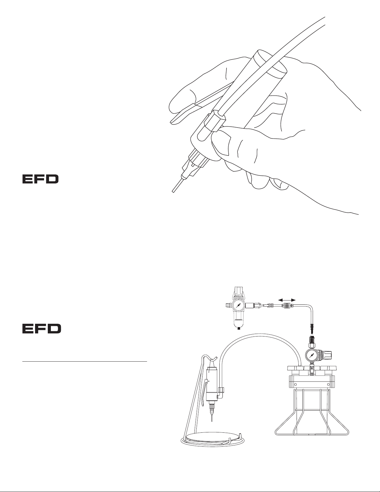
#615DTH
1.0 liter tank accommodates
a one pound bottle.
#61522
Hand-lever
valve stand
#2000F755
Five micron filter regulator for
clean, dry filtered factory air.
For dispensing with cyanoacrylates, order #2000756
with coalescing filter.
Shutoff valve
Typical system setup
USA: 800-556-3484 or +1-401-434-1680
Europe: 0800 585733 or +44 (0) 1582 666334
Asia: +86 (21) 5854 2345
technical@efd-inc.com www.efd-inc.com
For EFD sales and service in over 30 countries,
contact EFD or go to www.efd-inc.com/contact
EFD, Inc.
East Providence, RI USA
800-556-3484; +1-401-434-1680 (outside the USA)
info@efd-inc.com www.efd-inc.com
EFD International Inc.
Dunstable, Bedfordshire, UK
0800 585733 or +44 (0) 1582 666334
Ireland 00800 8272 9444
europe@efd-inc.com www.efd-inc.com
EFD, Inc., Asia
China: +86 (21) 5854 2345
china@efd-inc.com www.efd-inc.com/cn
Singapore: +65 6896 9630 sin-mal@efd-inc.com
©2006 Nordson Corporation 752V-HL-MAN-01 v062606
Electronic pdf files of EFD®manuals are also available at www.efdinc.com/manuals.html
®
A NORDSON COMPANY
®
A NORDSON COMPANY
Page 2
Service
Normal cleaning is accomplished by purging with appropriate solvent.
Some material, however, may cause a buildup on the fluid body and
diaphragm, which will require a periodic, thorough cleaning by removing
the fluid body.
To remove the fluid body:
Remove the two retainer screws. It is not always necessary to
remove the fittings from the fluid body for cleaning. If the fittings
must be removed, be careful—solidified material on the fitting thread
could cause the fluid body thread to strip out.
NOTE: Avoid using sharp probes for cleaning. Any scratches or nicks on
the diaphragm or the sealing side of the fluid body may cause the valve
to leak and require replacement of both the diaphragm and fluid body.
To reinstall the fluid body:
Align fluid body holes with diaphragm and air cylinder body holes,
and reinsert retainer screws. Tighten 1/2 turn after screws contact
the fluid body. Proper torque is 7” pounds.
If diaphragm holes do not line up with the tapped holes in the air
cylinder body, follow Step #4 below.
Getting started ...
1. Install the feed tube from the fluid reservoir to the inlet fitting and
tighten the compression nut to secure. The location of the inlet
fitting can be changed by removing the two fluid body retainer
screws and fluid body. Follow the service instructions to reinstall the fluid body with the inlet fitting in the desired position.
2. Apply air pressure to the fluid reservoir. Start with a low setting
of 20 psi (1.4 bar). If using an EFD fluid reservoir, refer to the
User’s Guide for further instructions.
3. Install an appropriate size dispensing tip to the outlet tip
adapter. Use large tips for high viscosity materials and small
tips for low viscosity.
4. Press the hand lever to begin fluid flow. Release lever to stop
fluid flow.
5. To achieve desired flow, change the size of the dispensing tip or
adjust the reservoir fluid pressure.
Maintenance Tools:
7/64" hex wrench (part #7509)
1/8" flat tip screwdriver (part #7508)
snap ring pliers (customer supplied)
6" adjustable wrench (customer supplied)
CAUTION: Check the reservoir pressure gauge prior to performing any
maintenance to assure that pressure is zero (0). To confirm this on EFD
tanks: slide the shutoff valve on the air hose away from the tank, and
open the pressure relief valve on the tank.
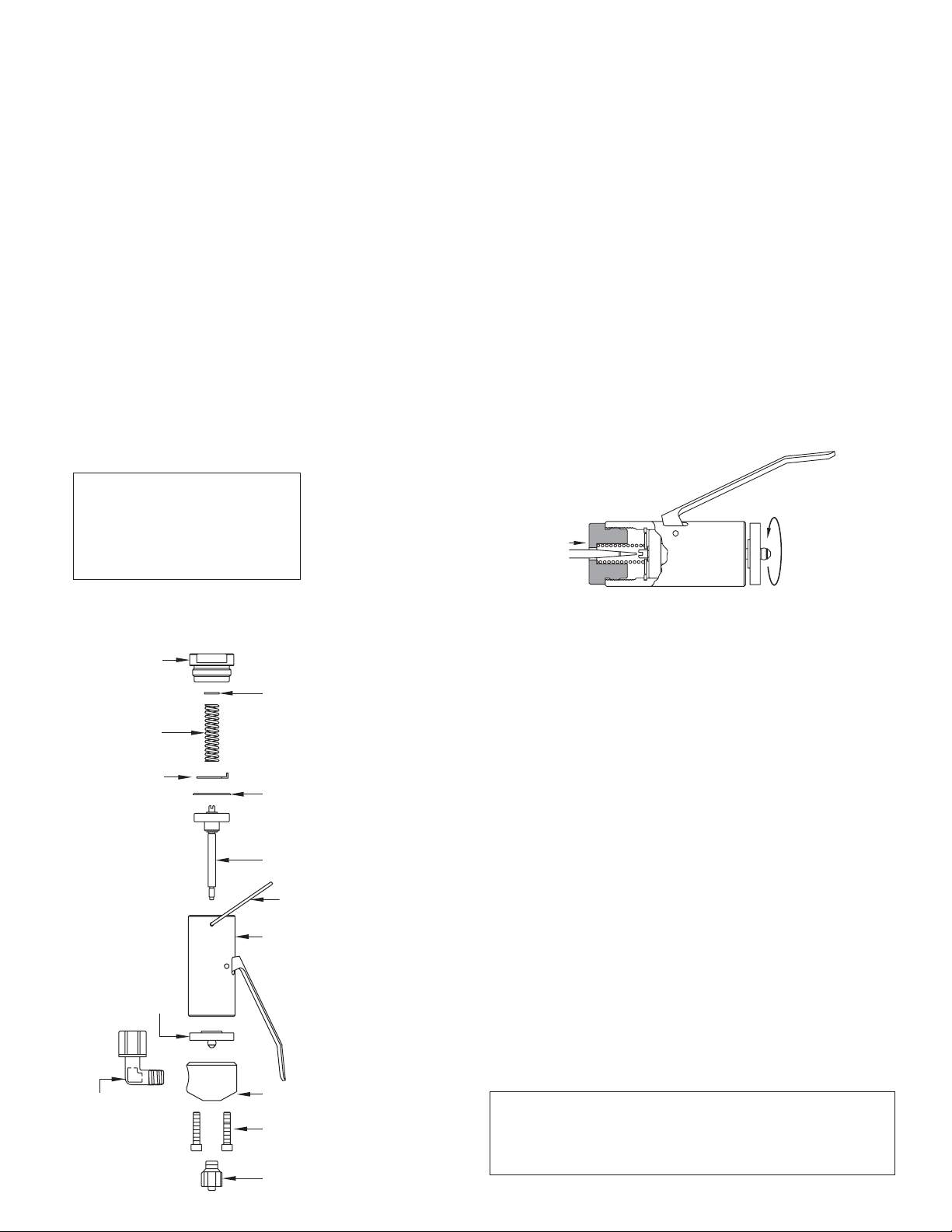
To change the diaphragm:
1. Remove the fluid body.
2. Place the 1/8" flat tip screwdriver (supplied) through the center
hole in the air cylinder cap.
See above.
Engage the slot in the
end of the piston shaft ➀. While holding the screwdriver, unscrew
the diaphragm counterclockwise ➁.
3. While holding the screwdriver, carefully thread on the new
diaphragm. Be careful not to strip or cross-thread the diaphragm
thread. Finger-tighten with medium pressure until the diaphragm
bottoms against the shoulder on the piston rod.
4. Before installing the fluid body, determine the operator’s desired
position of the fluid inlet fitting. Use the screwdriver inserted
through the hole in the air cylinder cap to align the holes on the
diaphragm with the appropriate holes in the air cylinder body.
Holding the air cylinder body, rotate the piston shaft clockwise
using the screwdriver until the appropriate holes line up.
5. Reinstall the fluid body. Tighten retainer screws 1/2 turn after
contacting the fluid body. Proper torque is 7 inch pounds.
➁ To unscrew
diaphragm,
turn counterclockwise.
➀ Engage the screwdriver into
the piston shaft and hold.
Air cylinder cap
Piston return
spring #7802
Tab washer
Diaphragm
Fluid inlet fitting
#7543BP
#7529
#7533
#7510
Thrust washer
#7809
Snap ring #7526
Piston and shaft assembly
#7523
Bail hanger #7412
Air cylinder and lever assembly
#7527HL
Fluid body #7521F
(2) Retainer screws
#7524
Tip adapter #7536NP
 Loading...