

Page 1
750V, 750V-SS and 751V
Dispense Valves
MAINTENANCE & PARTS GUIDE
IMPORTANT!
Save this Sheet.
Forward to
Maintenance or
Tool Crib
Supervisors
Electronic pdf files of EFD®manuals are also available at
www.efd-inc.com/manuals.html.
For EFD sales and service in over 30 countries,
contact EFD or go to www.efd-inc.com/contact
EFD, Inc.
East Providence, RI USA
800-556-3484; +1-401-434-1680 (outside the USA)
info@efd-inc.com www.efd-inc.com
EFD International Inc.
Dunstable, Bedfordshire, UK
0800 585733 or +44 (0) 1582 666334
Ireland 00800 8272 9444
europe@efd-inc.com www.efd-inc.com
EFD, Inc., Asia
China: +86 (21) 5854 2345
china@efd-inc.com www.efd-inc.com/cn
Singapore: +65 6896 9630 sin-mal@efd-inc.com
A NORDSON COMPANY
Page 2
Fluid Body
1. Remove the two retainer screws.
2. To reinstall the fluid body, align fluid
body holes with diaphragm and air
cylinder body holes and reinsert
retainer screws. Tighten in accordance with the following torque
specifications:
newton
Fluid body meters (inch pounds)
Acetal (black) 1.58 Nm (14 inch pounds)
UHMW*(yellow) 0.79 Nm (7 inch pounds)
Stainless steel 1.58 Nm (14 inch pounds)
*
Ultra High Molecular Weight
Diaphragm
3. Back-out stroke control knob two
turns counterclockwise from the
closed position.
4. Remove fluid body.
5. Unscrew diaphragm (counterclockwise) and remove it from
the piston rod.
6. Thread-on the new diaphragm
and tighten with medium pressure.
7. Align the holes of the diaphragm
with the appropriate holes in the
air cylinder body by inserting a
flat tip screwdriver through the
hole in the stroke control knob
and engage piston rod slot.
8. Rotate rod, piston and diaphragm
assembly clockwise until holes
are aligned.
9. Reinstall fluid body.
10. Turn stroke control knob clockwise until closed, and then
reopen to approximate stroke.
1
2
4
5
6
7
9
11
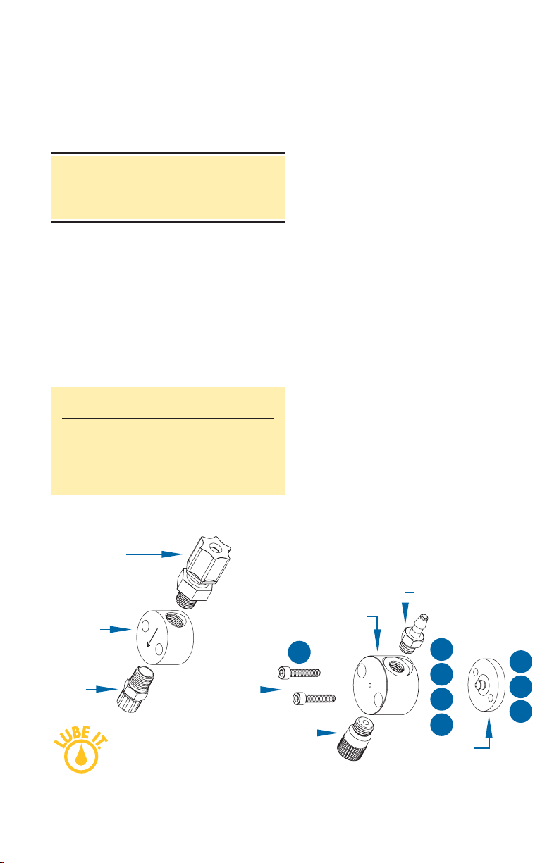
Valve Disassembly and
Reassembly Procedures
CAUTION: To prevent damage, the valve
must be disassembled starting at the fluid
outlet end of the valve.
www.efd-inc.com info@efd-inc.com USA 800-556-3484 Europe +44 (0) 1582 666334 Asia +86 (21) 5854 2345
Sales and service of EFD dispensing systems are available worldwide.
751V assembly
Fluid inlet fitting
Fluid inlet fitting
Fluid body
Tip
Adapter
(2) Retainer
screws
#7524
Tip Adapter
Fluid body
Diaphragm
UHMW
Page 3

Piston O-ring
11. Remove fluid body and diaphragm.
12. Remove stroke control knob and
spring by turning counterclockwise.
13. Remove the piston retainer ring and
anti-torque washer.
14. Remove the piston.
15. Lubricate O-ring, piston shaft and air
cylinder wall with Nye Lubricant #865.
16. Reinstall components in reverse order
of disassembly.
Tools required:
7/64" hex wrench
1/8" flat-tip screwdriver
6" adjustable wrench
6" needle-nose pliers
snap-ring pliers
Replacement Parts for Specific Valve Models
——— Fluid Body ———
Model UHMW Acetal Stainless* Fluid Inlet Fitting Tip Adapter Diaphragm
750V &
750V-SS 7521 n/a 7521-SS* 7511BP (1/8” ID Tube) 7514 7510
751V n/a 7521D 7521D-SS 7611BP (1/4” OD Tube) 7514B 7510
7610BP (3/8” OD Tube)
*optional
3
8
10
12
13
14
15
16
www.efd-inc.com info@efd-inc.com USA 800-556-3484 Europe +44 (0) 1582 666334 Asia +86 (21) 5854 2345
Sales and service of EFD dispensing systems are available worldwide.
Air cylinder body
#7527-SS (stainless steel)
#7527 (hard-coated aluminum)
Piston and rod
includes O-ring
#7518
Anti-torque washer
#7533
Air input hose & fitting
#78518A
Stroke control knob
#750SR-KIT (stroke reference, aluminum)
#750SSR-KIT (stroke reference,
stainless steel)
Piston spring #7525
Piston retainer ring
#7526
750SR-KIT
750V
750SSR-KIT
750V-SS
Page 4

Troubleshooting Guide
No fluid flow
• If valve operating air pressure is too low,
the valve will not open. Increase air
pressure to 70 psi (4.8 bar) minimum.
• The reservoir air pressure may not be
high enough. Increase pressure.
• The dispensing tip may be clogged.
Replace tip.
• The stroke adjustment may be closed.
Open stroke adjustment.
• Fluid may have solidified in the valve.
Clean the fluid body.
Fluid drools after the valve closes,
eventually stopping
• This is caused when air is trapped in the
outlet section of the fluid chamber or the
fluid has entrapped air. The air will expand
after the valve closes, causing extrusion
until the air reaches atmospheric pressure.
Purge the valve by dispensing at a steady
flow until clear. If a small tip is used, it
may be necessary to remove the tip while
purging to obtain sufficient flow to carry
the air down through the tip adapter.
• If the fluid has entrapped air, the material
must be degassed before dispensing.
Fluid drips at a steady rate after the
valve closes
• A steady drip can be caused by exces-
sive reservoir pressure. Check to be
sure the reservoir pressure is not above
70 psi (4.8 bar).
• If the stroke adjustment knob is turned-out
more than two full turns, resulting in reservoir pressure that will force the diaphragm
open. Check the stroke adjustment knob
to be sure it is less than two turns out.
• A steady drip also indicates failure of
the diaphragm to close fully due to particle build-up or wear. In either case,
replace the sealing head in accordance
with the maintenance instructions.
Fluid leaks out between fluid body and
diaphragm
• Fluid leakage between the fluid body and
diaphragm indicates the annular sealing ridge on the fluid body is damaged or
the fluid body is distorted due to excessive torque on the retaining screws. In
either case, replace the fluid body.
Fluid flows out of the drain hole
• Fluid flowing out of the drain hole indicates
a ruptured diaphragm. Replace in accordance with the maintenance instructions.
Valve responds slowly when opening
and closing
• Valve response is related to control air
hose length and size. The valve is supplied with 5-feet of 3/32” ID tubing
attached. Any additional length or size
change will affect response time. Check
to be sure the length and size have not
been changed.
Inconsistent deposits
• Inconsistent deposits can result if the
air pressure controlling the valve and/or
supplying the reservoir is fluctuating or if
the valve operating pressure is less than
70 psi (4.8 bar). Check to be sure air
pressures are constant and the valve
operating pressure is 70 psi (4.8 bar).
• The time the valve is open must be constant. Check to be sure the valve controller is providing a consistent output.
A NORDSON COMPANY
USA: 800-556-3484 or +1-401-434-1680
Europe: 0800 585733 or +44 (0) 1582 666334
Asia: +86 (21) 5854 2345
technical@efd-inc.com www.efd-inc.com
©2006 Nordson Corporation 750V-MAINT-01 v062606
 Loading...