

Page 1
Introduction
The 750 Series fluid dispense valves are simple to
use and will operate many millions of cycles without
maintenance. The 750 Series incorporates a variety
of compact, precise, adjustable diaphragm valves
for dispensing low to medium viscosity fluids. These
include the 750V, 750V-SS, 751V, 752V, 752V-SS,
752V-UH, 752V-UHSS, 752V-DVD and 752V-UHDVD
models.
All 750 Series valves use the same actuating assembly.
But fluid body styles and diaphragms differ according
to the model. The 752V Series fluid bodys are constructed with the outlet at the end of the fluid body.
The 750V and 751V fluid bodys are constructed with
the outlet on the side of the fluid body.
Each valve is shipped with a dispensing tip adapter,
fluid inlet fitting and 5-foot actuating air hose installed.
750 Series
Dispense Valve
INSTALLATION GUIDE
USA: 800-556-3484 or +1-401-434-1680
Europe: 0800 585733 or +44 (0) 1582 666334
Asia: +86 (21) 5854 2345
technical@efd-inc.com www.efd-inc.com
Electronic pdf files of EFD®manuals are also available at
www.efd-inc.com/manuals.html.
®
A NORDSON COMPANY
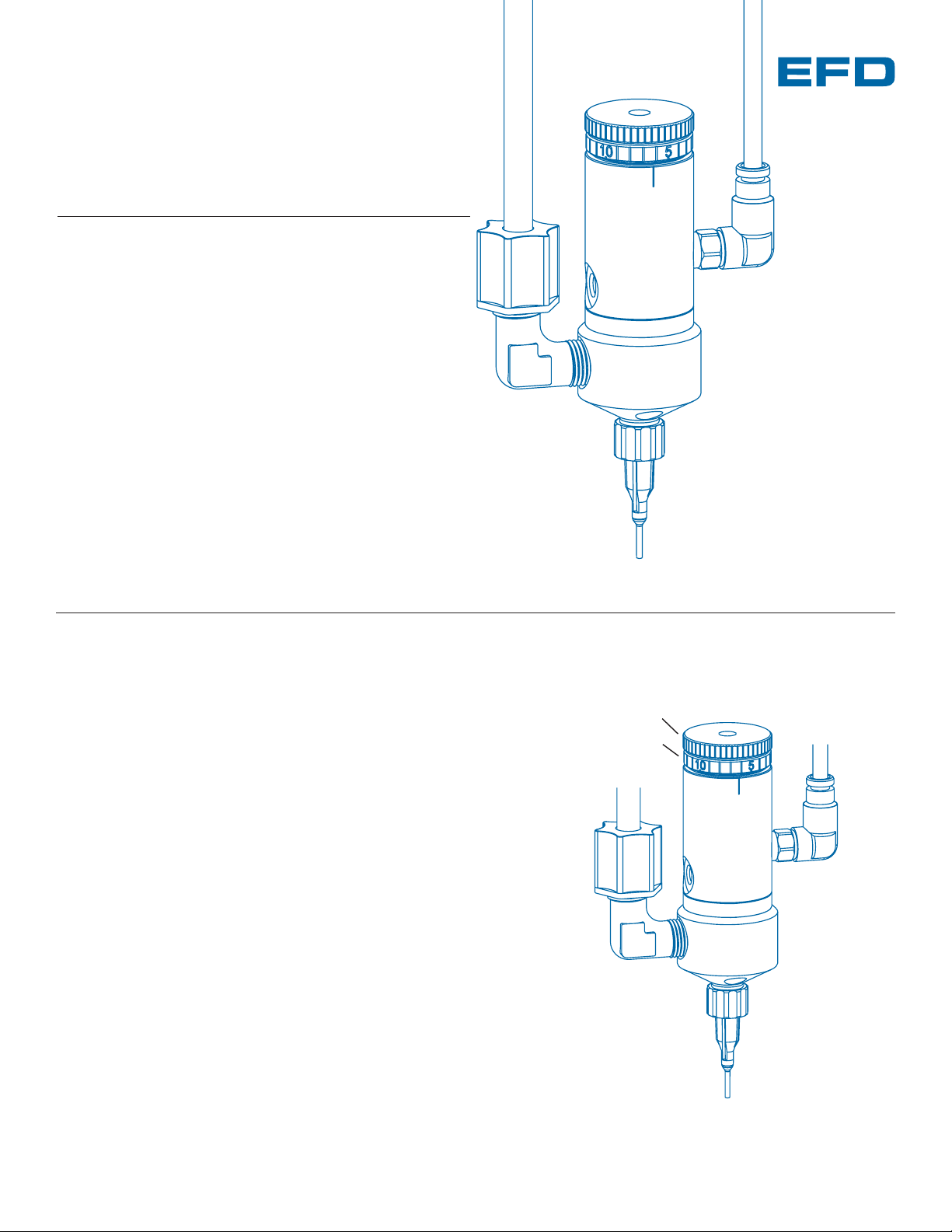
Stroke control knob
Stroke reference ring
Fluid supply line
Inlet fitting
Control
air hose
Fluid body
Dispensing tip
Page 2
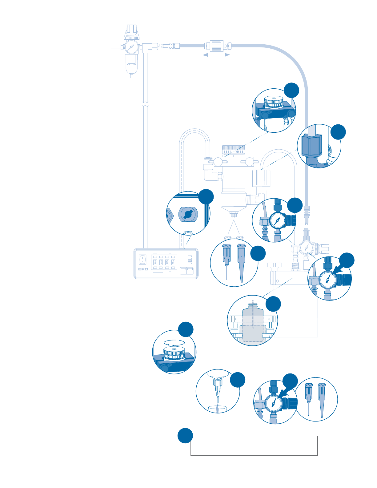
Installation
Set desired deposit size by adjusting valve open
time. Refer to valve controller operating manual.
11
1. Mount valve with an EFD universal
valve mount (#7002VM) or other fixture.
2. Connect fluid supply line to valve. If
3/8” OD tubing is used, change to
fitting #7610BP supplied.
3. Connect the fluid supply line to reservoir.
The reservoir can accept either OD or
1/4” OD or 3/8” OD tubing using
#62518PT supplied.
4. Connect valve control air hose to
ValveMate
™
controller (or other pneumatic switch) used to control valve
open time.
5. Choose a dispensing tip—small tips
(20 gauge) for low-viscosity fluids and
larger (14 gauge) for higher viscosities.
6. Fill reservoir by pouring fluid directly
into tank liner or manufacturer’s bottle
placed inside reservoir. Secure cover
prior to setting pressure.
7. Set reservoir pressure to low for thin
fluids and higher for thick fluids.
8. Set the diaphragm stroke starting with
no more than 1/2 turn open.
*
9. Place a cup under the dispensing tip
and actuate the valve until fluid lines,
valve and dispensing tip are free of air.
10. Set desired flow rate by adjusting
fluid reservoir pressure or changing
dispensing tip.
*
Do not overtighten the stroke adjustment knob or
open it more than two full turns. If open more than
two turns, pressurized liquid could force open the
diaphragm seal, resulting in continuous liquid flow.
9
Open
Close
8
Air Output
ut
Exhaust
r
Prior to installing this valve, please
read the associated reservoir and
valve controller operating instructions
to become familiar with the operation
of all components of the dispensing
system.
1
7
5
2
6
4
10
3
To exhaust
To pressurize
A NORDSON COMPANY
®
Steady
Test
Run
Setup Program
5
20
0
Time Set
Clear
Fast Slow
POWER
RUN
SETUP
CYCLE
Fast Slow
Time Set
Pressure
STOP
Time
Purge
Page 3

How the Valve Operates
Input air pressure at 70 psi (4.8 bar)
forces the internal piston ➀➀to move.
➁➁
The piston rod pulls open the
diaphragm seal,
➂➂
permitting fluid
flow. When the input air pressure is
relieved, the spring retracts the piston
and the diaphragm closes.
The primary control of deposit size is the valve open time.
ValveMate Concept
The ValveMate 7000 provides easy
adjustment of valve output for maximum
end-user convenience and efficiency.
Valve open time is the primary control of
deposit. The 7000 puts push-button
adjustment of valve open time where it
needs to be—at the valve.
Deposit size can be programmed by
pressing the PROGRAM button in the
SETUP mode. This affords an easy
starting point for selecting deposit size.
Note: The EFD Ultra®TT 325 and 525
XYZ automated dispensing systems have
integrated ValveMate controllers for
operating all EFD dispense valves.
The amount of fluid dispensed will
depend on the time the valve is open,
the viscosity of the fluid, the air pressure
in the fluid reservoir, the dispensing tip
size and the diaphragm stroke.
Flow rate is a function of reservoir
pressure, tip size and fluid viscosity.
closed
➁➁
➂➂
open closed open
To calibrate the valve, the “0” mark on
the stroke reference ring should align
with one of the two reference marks
on the valve body. When the set-screw
is tightened, the valve is calibrated.
➀➀
➂➂
➁➁
➀➀
➁➁
➂➂
➀➀
➂➂
➁➁
➀➀
752V and 752V-UH Fluid Flow 750V and 751V Fluid Flow
www.efd-inc.com technical@efd-inc.com USA 800-556-3484 Europe +44 (0) 1582 666334 Asia +86 (21) 5854 2345
Steady
Test
A NORDSON COMPANY
VALVEMATE
7000
®
Run
Setup Program
Rear Panel
air input
power input
(voltage selector)
air output to valve
I/O connector with alarm
output (<60 psi)
connector for
optional foot pedal
Purge
Time Set
Clear
Fast Slow
Fast Slow
Time Set
POWER
RUN
SETUP
CYCLE
Pressure
STOP
Time
Control Pad
set time
timer bypass
display pressure (psi, bar)
TEACH program
test cycle
purge
reset
Function Indicators
Pressure/Time Toggle
Emergency Stop
Page 4

Specifications
General
Diaphragm: UHMW* polyethylene
Air pressure required: 70 to 90 psi (4.8 to 6.2 bar)
Maximum fluid pressure: 70 psi (4.8 bar)
Maximum operating temperature: 43°C (110°F)
Mounting: (1) 10-32 UNF tapped hole
750V and 750V-SS
Size: 64.7 mm length x 23.8 mm diameter
(2.55” x 0.94” )
Weight: 750V – 93.5 grams (3.30 oz)
750V-SS – 165.8 grams (5.85 oz)
Air cylinder body: 750V – Hard-coated aluminum
750V-SS – Type 303 stainless
steel
Fluid body: UHMW* polyethylene
Free flow orifice: 1.57 mm diameter (0.062”)
Fluid inlet thread: 1/4-28 UNF
Output thread: 5/16-28 UNF
Tip adapter: Polypropylene
751V
Size: 64.7 mm length x 26.9 mm diameter
(2.55” x 1.06”)
Weight: 101.7 grams (3.59 oz)
Air cylinder body: Hard-coated aluminum
Fluid body: Acetal copolymer
Free flow orifice: 2.03 mm diameter (0.08”)
Fluid inlet thread: 1/8 NPT female
Output thread: 1/8 NPT female
Tip adapter: Nylon
752V, 752V-UH/752V-SS and 752V-UHSS
Size: 80.7 mm length x 26.9 mm diameter
(3.18” x 1.06”)
Weight: 752V and 752V-UH – 99.5 grams (3.51 oz)
752V-SS and 752V-UHSS – 181.9 grams
(6.42 oz)
Air cylinder body: 752V and 752V-UH – Hard-coated
aluminum. 752V-SS and 752VUHSS – Type 303 stainless steel
Fluid body: 752V and 752V-SS – Acetal copolymer
752V-UH and 752V-UHSS – UHMW*
polyethylene
Free flow orifice: 2.5 mm diameter (0.10”)
Fluid inlet thread: 1/8 NPT female
Output thread: 1/4-28 UNF
Tip adapter: Polypropylene
752V-DVD and 752V-UHDVD
Size: 80.7 mm length x 26.9 mm diameter
(3.18” x 1.06”)
Weight: 752V-DVD – 172.9 grams (6.1 oz)
752V-UHDVD – 99.5 grams (3.51 oz)
Air cylinder body: Type 303 stainless steel
Fluid body: 752V-DVD – Type 303 stainless steel
752V-UHDVD – UHMW* polyethylene
Free flow orifice: 2.5 mm diameter (0.10”)
Fluid inlet thread: 1/8 NPT female
Output thread: 1/4-28 UNF 752V-UHDVD
752V-DVD (not applicable)
Tip adapter: 752V-DVD – Aluminum
752V-UHDVD – Polypropylene
* Ultra High Molecular Weight
For consistent dispense valve operation and easy adjustment of
valve output, EFD recommends using the ValveMate 7000 controller on all automatic, semi-automatic and benchtop applications.
The EFD Ultra TT Series positioning systems incorporate dispensing control into the main system.
Contact the EFD Dispense Valve Systems Group for details.
For EFD sales and service in over 30 countries,
contact EFD or go to www.efd-inc.com/contact
EFD, Inc.
East Providence, RI USA
800-556-3484; +1-401-434-1680 (outside the USA)
info@efd-inc.com www.efd-inc.com
EFD International Inc.
Dunstable, Bedfordshire, UK
0800 585733 or +44 (0) 1582 666334
Ireland 00800 8272 9444
europe@efd-inc.com www.efd-inc.com
EFD, Inc., Asia
China: +86 (21) 5854 2345
china@efd-inc.com www.efd-inc.com/cn
Singapore: +65 6896 9630 sin-mal@efd-inc.com
©2006 Nordson Corporation 750-INSTALL-01 v062606
®
A NORDSON COMPANY
 Loading...