

Introduction
The 741V Series dispense valve is simple to use and will
operate many millions of cycles without maintenance.
The 741V Series valves are designed to apply low-viscosity
fluids with accurate, extremely close repeat deposit control.
The 741V and 741V-SS valves are ideal for use on automatic
assembly machines.
Each valve comes equipped with a 5-foot actuating air hose
and male quick-connect, adjustable stroke control and fluid
inlet fitting. The dispensing tip adapter features a SafetyLok
™
collar for secure dispensing tip attachment.
The 741V fluid body and air cylinder body are hard-coated
aluminum. The 741V-SS valve model has a Type 303 stainless
steel fluid body and air cylinder body.
741V Series Dispense Valve
INSTALLATION GUIDE
Electronic pdf files of EFD®manuals are also available at
www.efd-inc.com/manuals.html.
USA: 800-556-3484 or +1-401-434-1680
Europe: 0800 585733 or +44 (0) 1582 666334
Asia: +86 (21) 5854 2345
technical@efd-inc.com www.efd-inc.com
®
A NORDSON COMPANY
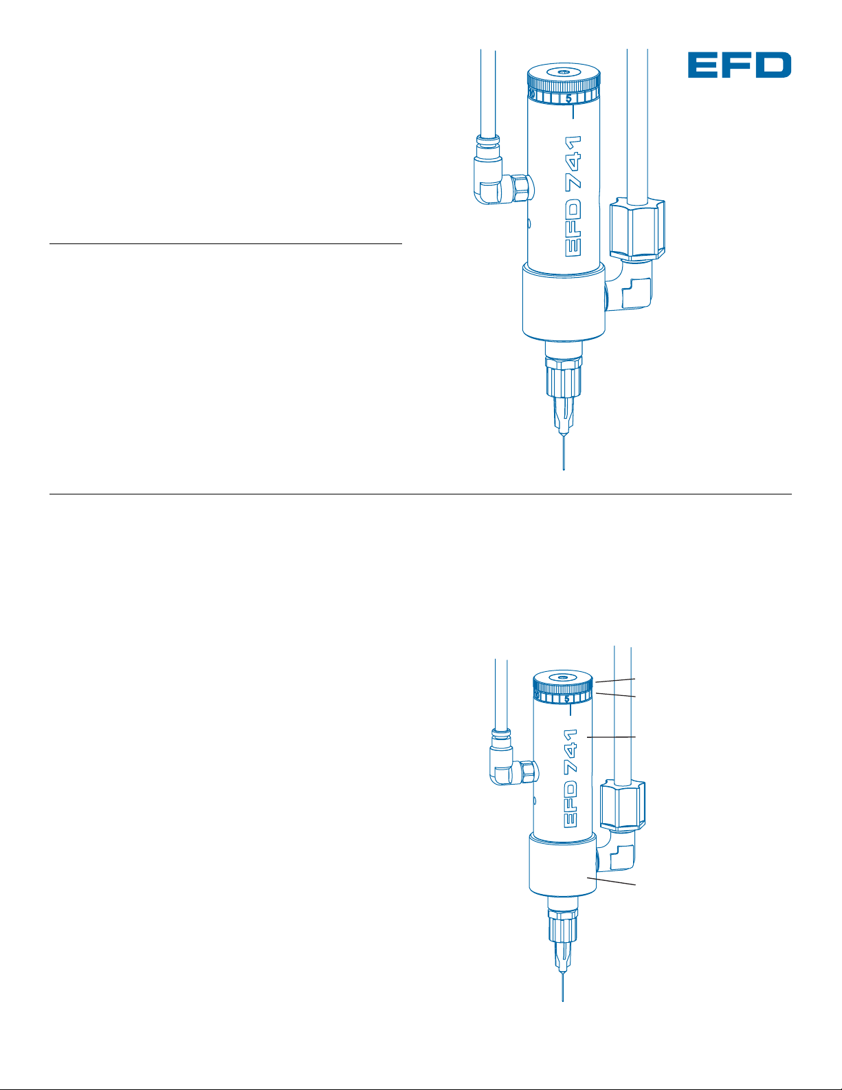
Control
air hose
Fluid
supply line
Stroke control knob
Stroke reference ring
Air cylinder body
Inlet fitting
Fluid body
Tip adapter
Dispensing tip
10
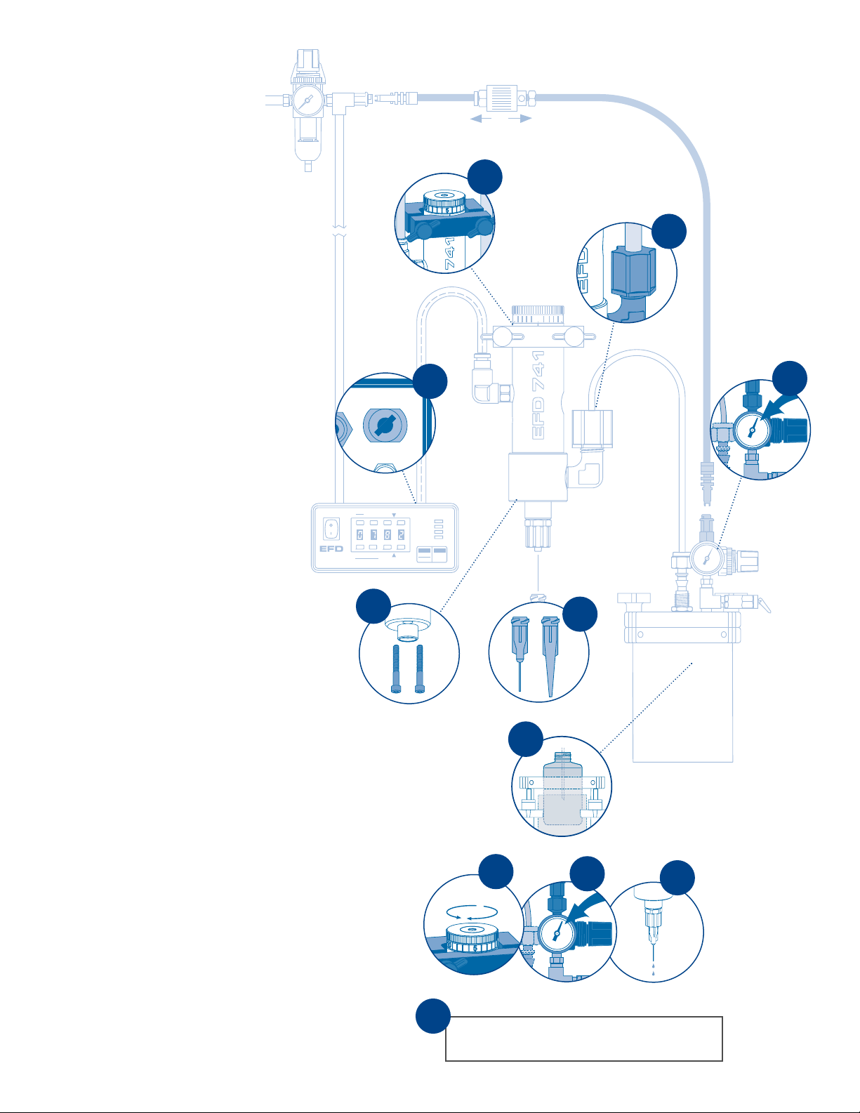
741V Installation
1. Mount valve with an EFD universal
valve mount (#7002VM) or other
fixture.
2. Connect valve control air hose to
ValveMate
™
controller (or other
pneumatic switch) used to control
valve open time.
3. Connect the fluid supply line to
the fluid inlet fitting (#7543BP is
installed for use with 1/4” OD
tubing) and to the reservoir.
4. To prevent interference with
machine parts, the fluid body
can be rotated to any new 45º
position. Remove the two screws
that attach the fluid body to the air
cylinder body, change position,
reinstall and tighten screws.
5. Install appropriate size dispensing
tip. The enclosed dispensing tip
adapter accepts EFD SafetyLok
dispensing tips. Use small diameter
tips for thin fluids and larger tips
for thick fluids.
6. Fill reservoir by pouring fluid directly
into tank liner or manufacturer’s
bottle placed inside reservoir.
Secure cover prior to setting
pressure.
7.
Set reservoir pressure to low for thin
fluids and higher for thick fluids.
8.
Set the needle stroke, starting at
one full turn open.
9. Set valve control air pressure at
70 psi (4.8 bar). Refer to valve
controller operating manual.
10.
Open the valve with an air pulse long
enough to fill the valve and start fluid
flow. Test the dispensed amount
with a nominal time setting.
5
Prior to installing this valve, please
read the associated reservoir and
valve controller operating instructions
to become familiar with the operation
of all components of the dispensing
system.
Open
Close
4
3
Set desired deposit size by adjusting reservoir
pressure, needle stroke and valve open time.
11
Air Output
ut
Exhaust
r
2
6
1
8
9
7
To exhaust
To pressurize
A NORDSON COMPANY
VALVEMATE
7000
®
Steady
Test
Run
Setup Program
5
Time Set
Fast Slow
Clear
Purge
Fast Slow
Time Set
Pressure
POWER
RUN
SETUP
CYCLE
STOP
Time
20
0
 Loading...