

EFD 741MD-SS INSTALLATION GUIDE

Introduction
The 741MD-SS Series is simple to use and will
operate many millions of cycles without maintenance.
The 741MD-SS is a pneumatically operated,
adjustable needle valve designed to apply precise
microdeposits of low to high viscosity fluids down
to fractions of a microliter. It is ideal for automated
assembly processes that require small dispensing
tips (from 22 to 33 gauge). The 741MD-SS provides
exceptional control and the absolute minimum dead
fluid volume.
741MD-SS Series
Dispense Valve
INSTALLATION GUIDE
Electronic pdf files of EFD®manuals are also available at
www.efd-inc.com/manuals.html.
USA: 800-556-3484 or +1-401-434-1680
Europe: 0800 585733 or +44 (0) 1582 666334
Asia: +86 (21) 5854 2345
technical@efd-inc.com www.efd-inc.com
®
A NORDSON COMPANY
Barrel reservoir
Barrel adapter assembly
Stroke reference ring
Control
air hose
Inlet fitting
Dispensing tip
Fluid body
0
1
0
2
0
3
0
40
50
60
7
0
80
9
0
100
7
6
5
4
3
2
1
0
1
0
2
0
3
0
40
50
60
7
0
80
9
0
100
7
6
5
4
3
2
1
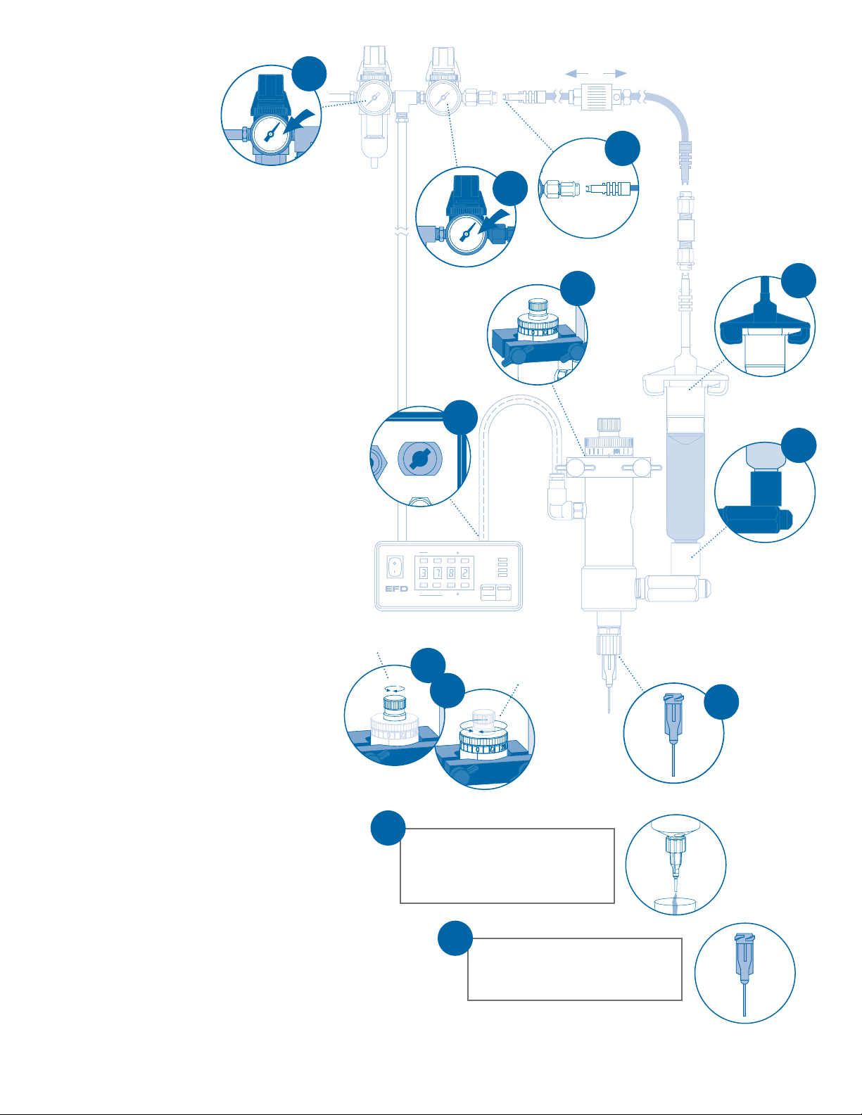
Installation
Open the valve with an air pulse
long enough to fill the valve and
start fluid flow. Test the dispensed
amount with a nominal time setting.
11
Set desired deposit size by changing
tip size, reservoir pressure, needle
stroke and valve open time.
12
1. Mount valve with an EFD universal valve
mount (#7002VM) or other fixture.
2. Connect valve control air line to
ValveMate
™
controller (or other pneumatic
switch) used to control operating air to
the valve.
3. Connect the white male quick-connect
on the flexible air line to the white female
quick-connect at the air pressure regulator.
4. Install the barrel reservoir on the fluid
inlet fitting (installed for use with
Ultra
®
barrel reservoirs). For low viscosity fluids,
fill the reservoir after installing it on the
fluid-inlet fitting. High viscosity materials
can be loaded into the reservoir before
installing on the inlet fitting.
Note: Fill barrels no more than 2/3 full. Always
use a SmoothFlow
™
piston when dispensing medium to high viscosity materials (see setup illustration).
5. Attach the barrel adapter head to the
barrel reservoir using air interconnect
coupler to connect the barrel adapter
assembly to the flexible air line.
6. Install appropriate size EFD SafetyLok
™
dispensing tip on the tip adapter. Tighten
the tip retaining nut fully to position the
needle hub against the shoulder of the
tip adapter.
7. Refer to back page for instructions on
calibrating the needle stroke.
8. Open stroke adjustment knob to desired
position (1/2 turn open is the recommended starting point).
9. Set reservoir pressure to low for thin
fluids and higher for thick fluids. Use the
in-line air shut-off valve to pressurize or
depressurize barrel reservoir.
10. Set valve control air pressure at 70
psi (4.8 bar). Refer to valve controller
operating manual.
Open
Close
Air Output
ut
Exhaust
r
Prior to installing this valve, please read the
associated reservoir and valve controller
operating instructions to become familiar
with the operation of all components of the
dispensing system.
5
2
4
00
1010
2020
303
0
4040
5050
606
0
707
0
8080
9090
1
0
0
1
0
0
77
66
55
44
33
22
11
1
9
00
1010
2020
303
0
404
0
5050
606
0
707
0
8080
9090
1
0
0
1
0
0
77
66
55
44
33
22
11
0
10
20
3
0
4
0
50
6
0
7
0
80
90
1
0
0
7
6
5
4
3
2
1
10
6
3
Open
Close
7
8
adjustment knob
calibration knob
50
60
40
4
7
3
0
0
3
5
2
80
0
2
6
1
1
0
0
9
7
0
100
50
60
40
4
7
3
0
0
3
5
2
80
0
2
6
1
1
0
0
9
7
0
100
To exhaust
To pressurize
A NORDSON COMPANY
®
Steady
Test
Run
Setup Program
5
Time Set
Clear
Fast Slow
POWER
RUN
SETUP
CYCLE
Fast Slow
Time Set
Pressure
STOP
Time
Purge
20
0
 Loading...