

Page 1
US: 88-333-0311
UK: 0800 585733
Mexico: 001-800-556-3484
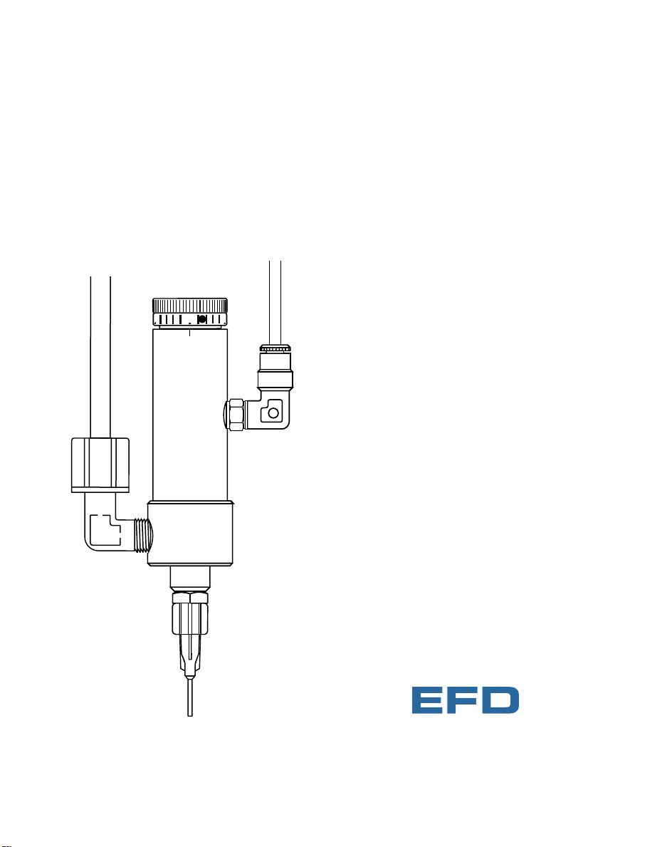
740V Series Dispense Valve
Operating Manual
20
0
5
®
A NORDSON COMP ANY
Page 2

If you require any assistance, or have
specific questions, please contact us.
US: 888-333-0311
Telephone: (401) 434-1680
Fax: (401) 431-0237
E-mail: technical@efd-inc.com
Mexico: 001-800-556-3484
UK: 0800 585733
EFD Inc.
977 Waterman Avenue, East Providence, RI 02914-1342 USA
Sales and service of EFD Dispense Valve Systems is available
through EFD authorized distributors in over 30 countries.
Please contact EFD U.S.A. for names and addresses.
Page 3

740V-MAN ©2003 EFD Inc.
This manual is for the express and sole use of EFD valve purchasers and
users, and no portion of this manual may be reproduced in any form.
Teflon is a registered trademark of E.I. DuPont.
EFD, VALVEMATE and SafetyLok are trademarks of EFD Inc.
Contents
Introduction..................................................................2
Specifications and Flow Chart ....................................3
How The Valve Operates..........................................4-5
Typical Setup ............................................................ 6
Setup Instructions........................................................7
740V-SS Exploded View ..............................................8
Maintenance and Cleaning ....................................9-12
Troubleshooting..........................................................13
Warranty ......................................................back cover
Page 4

Note: For consistent dispense valve operation and easy adjust-
ment of valve output, EFD recommends using the
VALVEMATE™7000 controller on all automatic, semiautomatic
and bench-top applications.
Contact EFD Dispense Valve Systems Group for details.
Introduction
The 740V Series dispense valves are precise, needletype valves manufactured to the highest quality standards. The valves are produced to very close tolerances
to ensure proper and reliable operation. Each valve has
been thoroughly tested prior to shipping.
The 740V valves are used with VALVEMATE™controllers for precise, repeatable outputs from a fraction of
a microliter up to continuous stripes of low to high viscosity fluids. It is an ideal valve for use on automatic
assembly machines.
Each valve comes equipped with a 5-ft actuating air
hose and male quick-connect, adjustable stroke control
and fluid inlet fitting. The dispensing tip adapter fea-
tures a SafetyLok™collar for secure dispensing tip
attachment.
To obtain the maximum performance from this fine
equipment, please read through these instructions
carefully.
2 / Introduction
Page 5
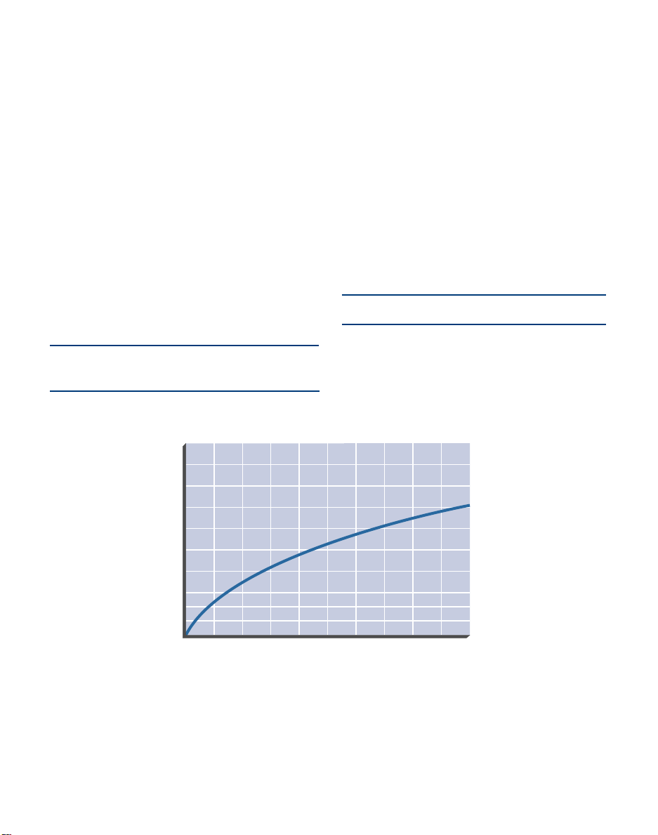
740V-SS Flow Chart
Free flow of water through tip adapter with no dispensing tip
restrictions.
Note: All stainless steel valve parts are passivate
d.
Construction
Air cylinder body: Hard-coated aluminum
Fluid chamber: 740V-SS: Type 303 stainless steel
740V: Hard-coated aluminum
Piston: Type 303 stainless steel
Needle: Type 303 stainless steel
Tip adapter/needle seat: Type 303 stainless steel
SafetyLok™collar: Nylon
Needle packings: Teflon
®
3 / Specifications and Flow Chart
Specifications
Size: 4.510" x 1.060" diameter
(114.6 mm x 26.9 mm)
Weight: 740V-SS: 9.0 oz (255 g)
740V: 6.36 oz (180.3 g)
Fluid inlet thread: 1/8 NPT Female
Fluid outlet: Male luer lock
Air pressure required: 70 psi (4.8 bar)
Maximum input fluid pressure: 300 psi (21 bar)
Mounting: 1/4-28 UNF tapped hole
Operation frequency: Exceeds 400 per minute
Output variation: ±0.5% nominal
Note:
Specifications and technical details are subject
to engineering changes without prior notification.
10 20 30 40 50 60 70 80 90 100
Reservoir Pressure - psi
0
Fluid Flow ml/second
5
10
15
20
25
30
35
40
45
50
Page 6

4 / How the Valve Operates
How the Valve Operates
The 740V Series valve is a normally closed, fail-safe,
adjustable opening needle valve.
The amount of fluid dispensed is determined by length
of time the valve is open; fluid reservoir pressure; output
dispensing tip size; needle stroke; and fluid viscosity.
The 740V Series require 70 psi (4.8 bar) air pressure.
This air pressure acting on the piston ➀ retracts the piston and needle ➁ from the needle seat ➂, permitting
fluid flow from the output tip adapter ➃. Piston and
needle stroke and fluid flow are controlled by the stroke
control knob ➄.
Once the cycle is complete, air is exhausted back
through the valve controller, ensuring rapid and positive
fluid shutoff.
The 740V Series can be operated in any position without affecting flow. Vibration normally has no effect on
performance. The valve can be moved in and out of dispense position at high-cycle rates (such as a reciprocating device installed on a production line) without
affecting dispensing performance.
➂
➀
➄
➁
➃
open
closed
Page 7

Stroke Control Reference
The Stroke Control Reference feature is used
to calibrate the stroke control setting or document the dispensing process.
To calibrate the valve, the stroke control
knob is first closed all the way. The set
screw is then loosened and the stroke reference ring turned so that the zero on the
reference ring is aligned with one of the two
reference marks engraved on the valve body.
When the set screw is tightened, the valve is
calibrated.
Tamper Resist Option
Any 740V Series valve can be ordered in the
tamper resist configuration to limit unauthorized adjustment.
In -TR configuration, stroke adjustment can
only be made when a special stroke control
knob is inserted into the stroke mechanism.
A kit can also be ordered as a retrofit for
existing valves.
Part # Description
740V-TR Tamper resist 740V valve
7544SS Tamper resist stroke kit
5 / How the Valve Operates
Removable
stroke control
knob
Stroke
mechanism
20
0
5
Stroke
reference
ring
Reference
mark
Stroke control
knob
Set screw
Page 8

CAUTION: Always depressurize the reservoir before opening. To do this,
slide the shutoff valve on the air line away from the reservoir. If using an EFD
tank reservoir, open the pressure relief valve as well. Before opening the
reservoir, check the pressure gauge to verify that pressure is zero (0).
Typical Setup
6 / Typical Setup
Flexible air line
#2310S
Black quick-connect
#7543BP for 1/4"
OD tube (installed)
#7610BP for 3/8"
OD tube (optional)
Five-micron filter regulator #2000F755
Set at 70 psi (4.8 bar)
Air tee #1116
To pressurizeTo exhaust
White quick-connect
Fluid feed hose
Pressure relief
Pressurized reservoir
with air regulator
20
0
5
POWER
RUN
SETUP
CYCLE
STOP
Clear
Purge
Run
Setup Program
Fast Slow
Time Set
Pressure
Time
Fast Slow
Time Set
Test
Steady
Note: Use only oil-free,
clean, dry filtered air.
Fluid inlet fitting
740V
valve
Control air line
Shutoff valve
VALVEMATE
7000 Controller
Pulsed air for
valve operation
®
A NORDSON COMPANY
Page 9

Figure 1
➁ Rotate fluid
chamber to desired
position.
➀ Set stroke
adjustment two
full turns out.
Note: Do not rotate fluid chamber more than one
complete turn.
Install an appropriate size dispensing tip on
the output tip adapter. The adapter accepts
EFD SafetyLok™tips. Use small diameter
(20 to 25 gage) for low viscosity fluids, and
larger tips (14 to 18 gage) for higher viscosity fluids.
Fill the fluid reservoir (refer to reservoir user's
guide).
After filling, check to be certain the reservoir
cover is secured and that all connections
are tight.
Set the reservoir pressure. For low viscosity
fluids, start with a pressure of approximately
5 psi (0.3 bar). For higher viscosity, use 20 to
40 psi (1.4 to 2.8 bar). Increase or decrease
as necessary.
Note: If solvents or other watery fluids are to be
dispensed in very small amounts, specify 0 to 15
psi (0 to 1.0 bar) precision regulator to control
reservoir pressure.
Set the needle stroke. Start at one full turn
open.
Set the valve control air pressure to 70 psi
(4.8 bar). Refer to the VALVEMATE™7000
manual.
Open the valve with an air pulse long
enough to fill the valve and start fluid flow.
Then test the dispensed amount with a
nominal time setting.
Increase or decrease reservoir pressure,
needle stroke and valve open time to arrive
at the desired deposit size.
Setup
Mount the 740V valve with an EFD universal
valve mount (#7002VM) or other appropriate
fixture, using the 1/4-28 UNF tapped hole on
the air cylinder body.
The 740V Series valves are shipped with the
fluid inlet fitting installed for use with 1/4" OD
x 1/8" ID flexible fluid hose. An optional fluid
inlet fitting for 3/8" OD tube is enclosed.
Connect the control air line to the valve controller or other pneumatic switch that is used
to control operating air to the valve. (Refer to
EFD VALVEMATE™7000 operating manual.)
Connect the fluid feed hose to the fluid inlet
fitting and fluid reservoir.
The valve fluid chamber with inlet fitting can
be rotated to prevent possible interference
with machine parts (See Figure 1).
To reposition the fluid chamber, first turn the
needle stroke control out two full turns ➀ ,
then rotate the chamber ➁ to the desired
position.
7 / Setup Instructions
20
0
5
Page 10

Items included in
repair kit #740V-RK
are underlined
and listed in blue.
740V Exploded View
Nye gel lubricant, 1 gram
foil packet (not shown)
#H-147-P
8 / Exploded View
Tip adapter/seat assembly
#7401
O-ring (Buna) #7517
Needle packing assembly
#7810
Piston return spring #7802
Snap ring #7526
O-ring (Buna) #7519
Air cylinder body
#7811-SS (stainless steel)
#7811 (aluminum)
O-ring (Buna) #7806
Retaining washer
#7807
Packing spring #7808
Air input hose
#78518A
O-ring (Viton) #5148RV
Fluid inlet fitting
#7543BP (installed) for 1/4" OD tubing
#7610BP (supplied) for 3/8" OD tubing
Thrust washer
#7809
Fluid chamber
#7402-SS (stainless steel)
#7402 (aluminum)
Piston and needle assembly
#7805-SS
20
0
5
Needle stroke control
#780SR-KIT (aluminum)
#780SSR-KIT (stainless steel)
SafetyLok collar
#7403
Page 11

Maintenance Tools
6" adjustable wrench
snap ring pliers
packing extraction tool #7803
Figure 1
Pushing the needle packings
from the fluid chamber.
Maintenance and Cleaning
Normal cleaning is accomplished by purging with
appropriate solvent. The tip adapter/seat assembly can
be removed (after the reservoir pressure has been bled
off) for cleaning without demounting the valve.
CAUTION: Always relieve the reservoir pressure and disconnect
the power before performing any maintenance on the system. On
all EFD tank reservoirs, there is a pressure relief valve that should
be activated before opening the reservoir to ensure that all pressure is bled off.
On all EFD cartridge reservoirs, the unique threaded design provides fail-safe air pressure release during cap removal.
To thoroughly clean valve chamber and replace needle
packings:
1. Remove the needle stroke control and piston
return spring to prevent damage to the needle and
seat during reassembly. Turn counterclockwise
until free.
2. Remove the inlet fitting and tip adapter/seat
assembly from the fluid chamber.
3. Remove the fluid chamber from the cylinder body
by turning counterclockwise until free. Then
remove the O-ring from the fluid chamber.
4. Remove the needle packings from the fluid chamber, using tool #7803 supplied with the valve.
Insert through outlet end of the fluid chamber and
gently push out the packings (see Figure 1).
Do not use sharp instruments to scrape or clean
these components. Scratches may cause the valve
to leak.
5. Remove any remaining packings and the packing
spring from the needle.
Continued on Next Page
9 / Maintenance and Cleaning
Packing extraction
tool #7803
Fluid chamber
O-ring
Needle packing
assembly
Page 12

Note: The lower cylinder needle O-ring is held in place by a flat
retaining washer that also serves as the packing spring seat. The
washer may come out with the spring. Ensure that it is back in
place before reinstalling the packing spring (see Figure 2).
6. Clean the needle with a cloth dampened in solvent.
7. Lubricate the needle with Nye Lubricant #865 gel
(EFD #H-147-P). Reinstall the needle packing
spring and new packing kit in accordance with
Figure 2.
8. Install a new O-ring (#7517) on the fluid chamber.
Screw the cylinder onto the fluid chamber. Hand
tighten only. The chamber can be turned back out
up to one turn to orient the fluid inlet fitting to the
desired position.
9. Reinstall the tip adapter/seat assembly.
10. To reinstall the piston return spring, first put one
thrust washer over the spring pilot (at the top of the
piston), then the other thrust washer into the needle
stroke control, followed by the spring.
11. Reinstall the needle stroke control by aligning the
piston return spring with the spring pilot. Turn the
needle stroke control clockwise until it stops and
then back it out to the desired setting.
Figure 2
Proper assembly order for reinstalling needle packings.
10 / Maintenance and Cleaning
Needle
packings
Packing
seat
Packing
expander
Air cylinder
body
O-ring
Retaining
washer
Spring
Continued on Next Page
Page 13

T o replace the piston and needle assembly or piston O-ring:
1. Remove the needle stroke control by turning counterclockwise until free.
2. Remove the piston return spring and thrust washers located on each end of the spring.
3. Remove the snap ring using snap ring pliers.
4. Pull the piston and needle assembly out of the
cylinder, using small pliers on the spring pilot (at
the top of the piston).
Note: The piston and needle assembly is replaced as a unit and
cannot be disassembled.
5. Clean the cylinder body wall and apply Nye
Lubricant #865 gel (EFD #H-147-P).
6. Replace the O-ring on the piston, apply Nye
Lubricant #865 gel (EFD #H-147-P), then reinstall in
the cylinder.
7. Reinstall the snap ring.
8. To reinstall the piston return spring, first put one
thrust washer over the spring pilot, then the other
thrust washer into the needle stroke control, followed by the spring.
9. Reinstall the needle stroke control by aligning the
piston return spring with the spring pilot. Turn the
needle stroke control clockwise until it stops and
then back it out to the desired setting.
Note:
Do not overtighten the needle stroke control, or needle
damage will occur.
11 / Maintenance and Cleaning
Continued on Next Page
Page 14

Note: After performing maintenance, the valve should be leak
tested before it is returned to service.
To leak test the valve:
1. Set the needle stroke control at two turns open.
2. Shut off actuating air. Install an air hose in the
valve's fluid inlet and connect it to a 100 psi (7 bar)
air supply.
3. Submerge the tip adapter/seat assembly in a container of water. If air bubbles appear, perform the
following procedure to reseat the parts.
To reseat the needle and tip adapter/seat assembly:
1. Disconnect or shut off all air to the valve.
2. Open the needle stroke control two turns.
3. Using the appropriate wrench, loosen the tip
adapter/seat assembly one full turn, then turn it
back in and retighten. This causes any small irregularities on the needle and seat to conform with one
another and become a matched set.
4. Restore actuating air and cycle the valve a few
times, then perform the leak test again.
5. Steps 3 and 4 may be repeated up to three times to
obtain satisfactory results.
6. If the valve continues to leak after three attempts to
reseat the needle, replace the needle and tip
adapter/seat assembly.
Bubble test for leaks.
No air bubbles should appear.
12 / Maintenance and Cleaning
20
0
5
Page 15

Inconsistent deposits.
Fluid leaks out the drain hole.
Steady drip.
Troubleshooting Guide
No fluid flow.
Valve Trouble Possible cause and correction
13 / Troubleshooting
Air operating pressure may be too low. Increase air
pressure to 70 psi (4.8 bar).
The reservoir air pressure may not be high enough.
Increase pressure.
The needle stroke adjustment may be closed. If it is
closed, open counter-clockwise one full turn.
Material may have clogged the valve head or output tip
adapter.
Clean the valve. (Refer to Maintenance & Cleaning on
pages 9-12.)
A steady drip can be caused by a worn needle and seat,
or a particle holding the needle off the seat.
Remove the tip adapter/seat assembly, clean and
inspect the needle and seat for wear. Replace worn or
damaged parts.
Fluid leaking out the drain hole on the side of the valve
indicates the needle packings are worn. Replace needle packings.
Inconsistent deposits can result if:
1. Air pressure controlling the valve is fluctuating.
2. Air pressure supplying the reservoir is fluctuating.
3. Air pressure controlling the valve is less than 70 psi
(4.8 bar).
Check to be sure the air pressures are constant and the
valve operating air pressure is 70 psi (4.8 bar).
The time the valve is open must be constant. Check to
be sure the valve controller is providing a consistent
output.
Page 16

977 Waterman Avenue, East Providence, Rhode Island 02914-1342 USA
U.S. toll free: 888-333-0311 Mexico: 001-800-556-3484
Telephone: 401-434-1680 Fax: 401-431-0237 www.efd-inc.com
e-mail: technical@efd-inc.com
Unit 14, Apex Business Centre, Boscombe Road, Dunstable, Beds. LU5 4SB UK
Telephone: 01582 666334 Fax: 01582 664227 UK: 0800 585733
Ireland: 00800 8272 9444 e-mail: uk@efd-inc.com
EFD International Inc. is incorporated with limited liability in the U.S.A.
EFD ONE YEAR LIMITED WARRANTY
All components of EFD Dispense Valves are warranted for one year from date of
purchase to be free from defects in material and workmanship (but not against
damage caused by misuse, abrasion, corrosion, negligence, accident, faulty
installation or by dispensing material incompatible with equipment) when the
equipment is installed and operated in accordance with factory recommendations
and instructions. EFD will repair or replace free of charge any part of the equipment thus found to be defective, on authorized return of the part prepaid to our
factory during the warranty period. The only exceptions are those parts which
normally wear and must be replaced routinely, such as but not limited to valve
needle packings and needle assemblies.
In no event shall any liability or obligation of EFD arising from this warranty
exceed the purchase price of the equipment. This warranty is valid only when oilfree, clean, dry, filtered air is used.
EFD makes no warranty of merchantability or fitness for a particular purpose. In
no event shall EFD be liable for incidental or consequential damages.
©2003 EFD Inc.
740V-MAN 1.5P403
®
A NORDSON COMP ANY
 Loading...