

Page 1
Introduction
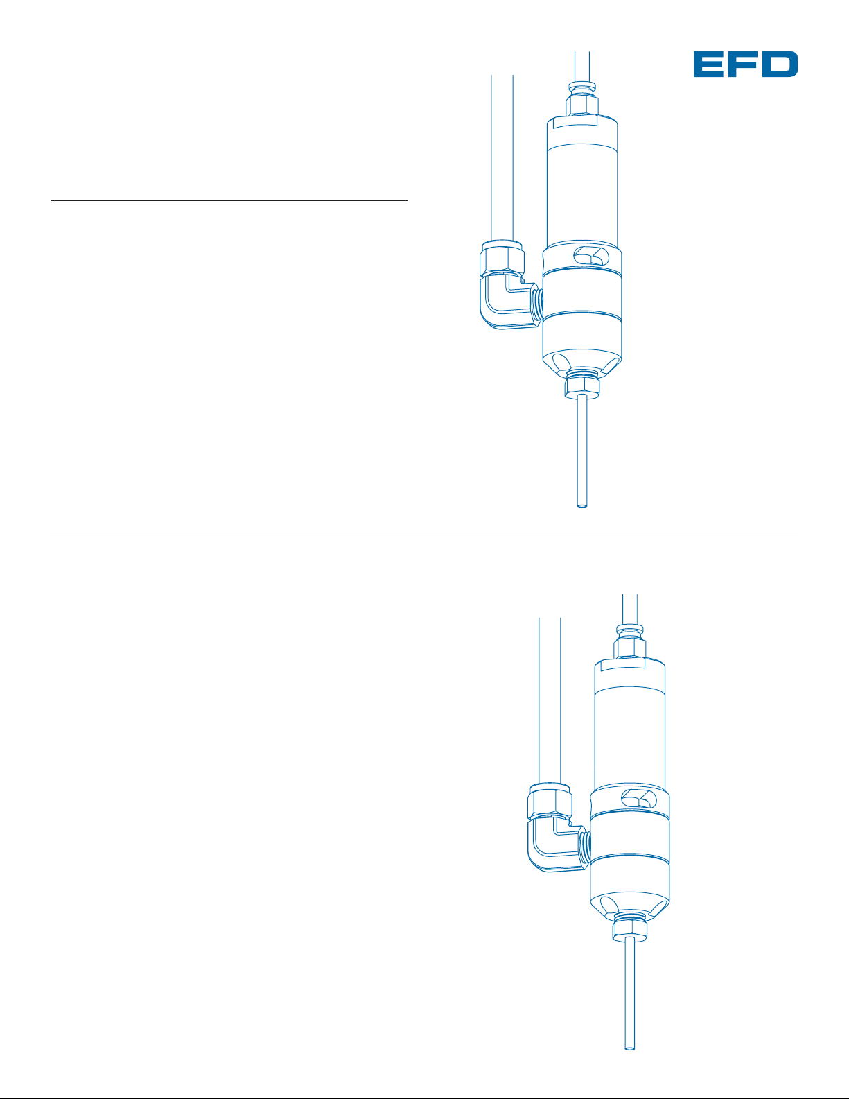
The 736HPA is a normally closed, air-actuated, balanced
spool-type valve designed to operate at fluid pressures
up to 2,500 psi (172 bar). Ideal for consistent dispensing
of industrial sealants and greases, the 736HPA valve is
simple to use and will operate many millions of cycles
without wear or leakage.
®
736HPA High Pressure
Dispense Valve
INSTALLATION GUIDE
r
USA: 800-556-3484 or +1-401-434-1680
Europe: 0800 585733 or +44 (0) 1582 666334
Asia: +86 (21) 5854 2345
technical@efd-inc.com www.efd-inc.com
Electronic pdf files of EFD®manuals are also available at
www.efd-inc.com/manuals.html.
A NORDSON COMPANY
Control air hose
Fluid supply line
Air cylinde
body
Fluid inlet fitting
Dispensing tip
Page 2
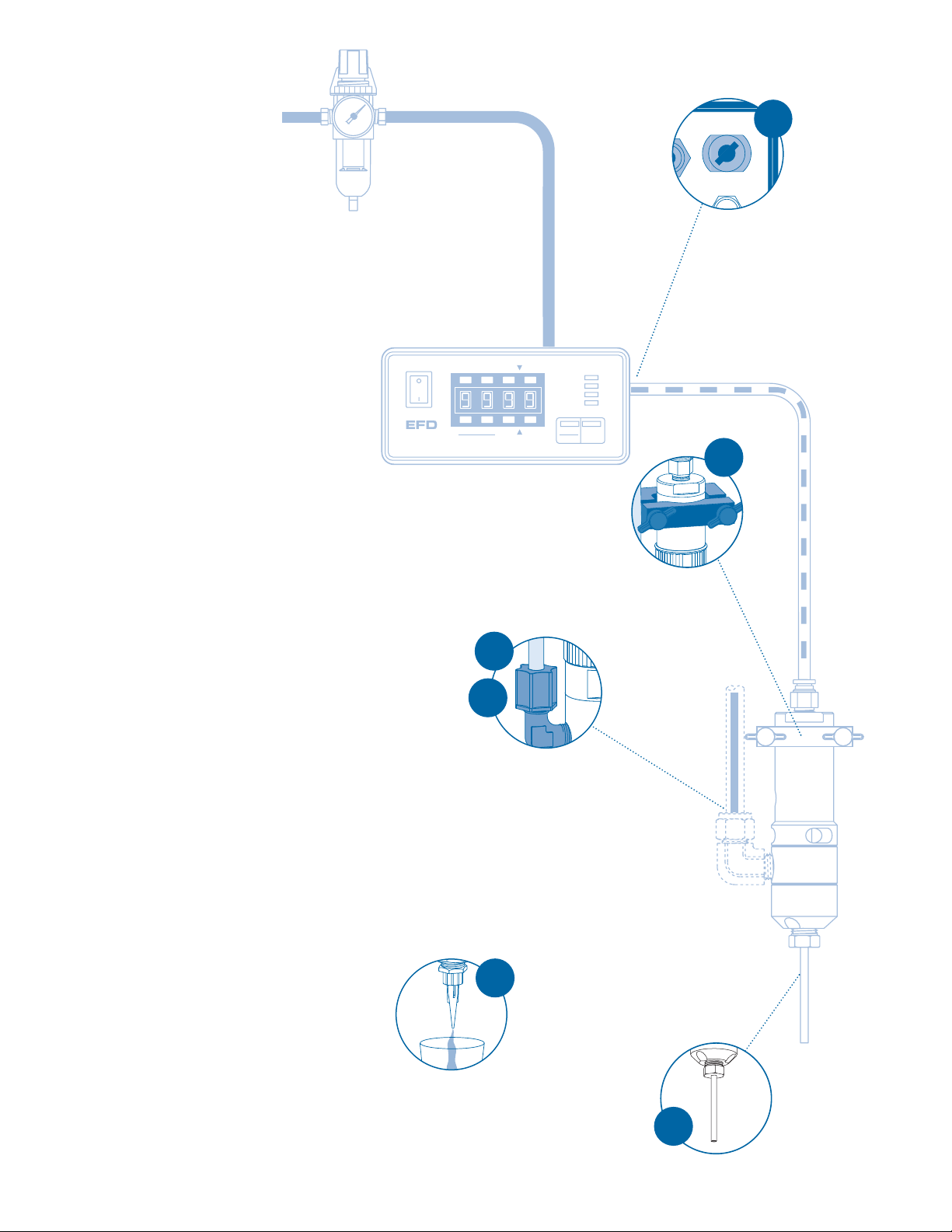
Installation
1. Mount valve with an EFD universal
valve mount (#7002VM) or other
fixture.
2. Thread the fluid inlet fitting into
the fluid inlet hole.
Note: The fluid inlet fitting and hose
must be obtained from the high
pressure pump supplier. Ensure that
the hose and fitting are rated for the
maximum operating pressure of the
pump system.
3. Connect the fluid feed hose to
the fitting.
4. Connect valve control air hose to
the ValveMate
™
controller (or other
pneumatic switch) used to control
valve open-time.*
5. Install appropriate threaded nozzle
to the valve output or use a
dispensing tip adapter (#2186) with
EFD SafetyLok
™
dispensing tips.
6. Check to be sure all fluid and air
connections are tight.
7. Make sure valve operating
pressure is set at 70 psi (4.8 bar).
8. Be sure delivery pump pressure
does not exceed 2,500 psi
(172 bar).
9. Place a cup under the dispensing
tip or nozzle and actuate the
valve until fluid flows steady.
10. Set desired flow rate by adjusting
fluid pressure or changing the
outlet tip size.
11. Set desired deposit size by
adjusting valve open-time. Refer
to valve controller operating
manual.
Prior to installing this valve, please
read the associated reservoir and
valve controller operating instructions
to become familiar with the operation
of all components of the dispensing
system.
1
5
2
3
Air Output
Exhaust
4
9
VALVEMATE
7000
Setup
Test
Purge
Fast Slow
Run
Program
Time Set
POWER
SETUP
CYCLE
Pressure
Time
RUN
STOP
Time Set
Clear
Fast Slow
Page 3
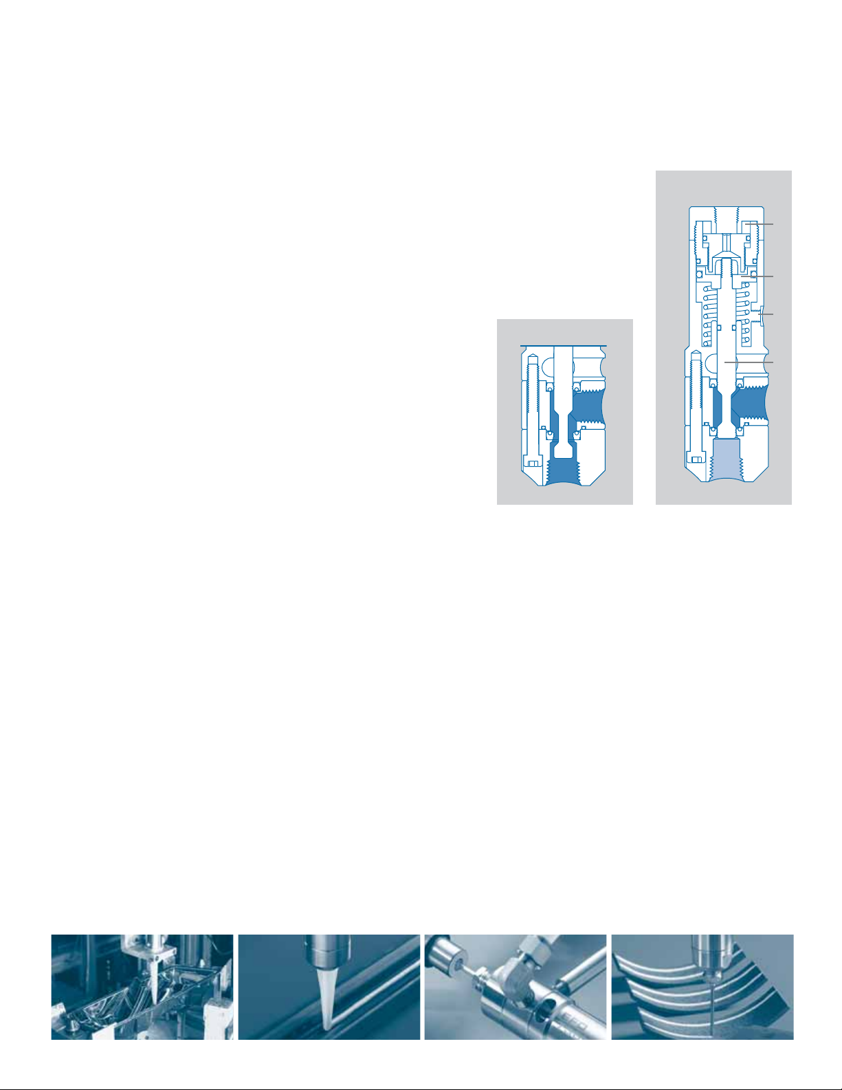
How the Valve Operates
open closed
➃➃
➂➂
➁➁
➀➀
When air pressure at 70 psi (4.8 bar) is applied, the piston shifts the
spool
➀➀
to the open position, allowing fluid to flow. At the end of the
cycle, spring force on the piston
➁➁
shifts the spool to the closed
position, stopping fluid flow. During the closing action, the 736HPA
provides snuff-back of fluid for clean cutoff.
The stroke adjustment
➂➂
can be used to regulate snuff-back to an
amount appropriate for the fluid being dispensed. Stroke adjustment
can also be used to reduce fluid surge when the valve opens to ensure
consistent bead widths and dot profiles. The stroke is adjusted by
moving the stroke limit stop:
1. To access the stop, first remove the air input hose from the push-in
air coupling by pushing down on the release ring while pulling up
on the tubing.
2. Insert the 1/8” Allen wrench through the air coupling and engage
the stroke limit stop.
3. Adjust the stop toward or away from the piston to vary the stroke.
To decrease the amount of opening surge and closing snuff-back,
extend the limit stop by turning the wrench clockwise. To increase
the amount of surge and snuff-back, retract the limit stop by
turning the wrench counterclockwise.
Note: Adjusting the stroke does not affect the flow rate.
4. Install the air input hose by pushing the hose into the coupling.
Note: For striping applications, fluid surge can be reduced further by
lowering the valve operating air pressure down to, but not below,
40 psi (2.7 bar).
When dispensing very thick fluids at high cycle rates, the double-acting
feature ensures rapid closure. A double-actuating air input
➃➃
is provided
on the side of the air cylinder to allow double-acting operation using air
pressure to both open and close the valve.
The amount of fluid dispensed is determined by valve open-time, fluid
pressure, dispensing tip size and fluid viscosity.
www.efd-inc.com technical@efd-inc.com USA 800-556-3484 Europe +44 (0) 1582 666334 Asia +86 (21) 5854 2345
Page 4
Specifications
General
Size: 116.1 mm length x 34.9 mm diameter
(4.57” x 1.375” )
Weight: 18.9 oz (537 grams)
Air cylinder body: Type 303 stainless steel
Fluid body and cap: Type 303 stainless steel
Fluid inlet thread: 1/4 NPT female
Output thread: 1/4 NPT female
Piston: Hard-coated aluminum
Spool: Hardened stainless, hard-chrome coated
Spool seals: Hytrel
®
(Viton®optional)
Air pressure required: 70 psi (4.8 bar)
Maximum fluid pressure: 2,500 psi (172 bar)
Mounting hole: 5/16-24 UNF tapped hole or
adjustable mounting block
ValveMate Concept
The ValveMate 7000 provides easy adjustment of valve
open-time for maximum end-user convenience and
efficiency. Valve open-time is the primary control of deposit
size. The 7000 puts push-button adjustment of valve
open-time where it needs to be – at the valve location.
Deposit size can be programmed by pressing the
PROGRAM button in the SETUP mode. This affords an
easy starting point for selecting deposit size.
Note: The EFD Ultra®TT 325 and 525 XYZ automated
dispensing systems have integrated ValveMate controllers
for operating all EFD dispense valves.
For consistent dispense valve operation and easy adjustment
of valve output, EFD recommends using the ValveMate 7000
controller on all automatic, semi-automatic and benchtop
applications.
The EFD Ultra TT Series positioning systems incorporate
dispensing control into the main system.
Contact the EFD Dispense Valve Systems Group for details.
For EFD sales and service in over 30 countries,
contact EFD or go to www.efd-inc.com/contact
EFD, Inc.
East Providence, RI USA
800-556-3484; +1-401-434-1680 (outside the USA)
info@efd-inc.com www.efd-inc.com
EFD International Inc.
Dunstable, Bedfordshire, UK
0800 585733 or +44 (0) 1582 666334
Ireland 00800 8272 9444
europe@efd-inc.com www.efd-inc.com
EFD, Inc., Asia
China: +86 (21) 5854 2345
china@efd-inc.com www.efd-inc.com/cn
Singapore: +65 6896 9630 sin-mal@efd-inc.com
Hytrel and Viton are registered trademarks of DuPont.
©2006 Nordson Corporation 736-INSTALL-01 v062606
Purge
Time Set
Clear
Fast Slow
Fast Slow
Time Set
POWER
RUN
SETUP
CYCLE
Pressure
STOP
Time
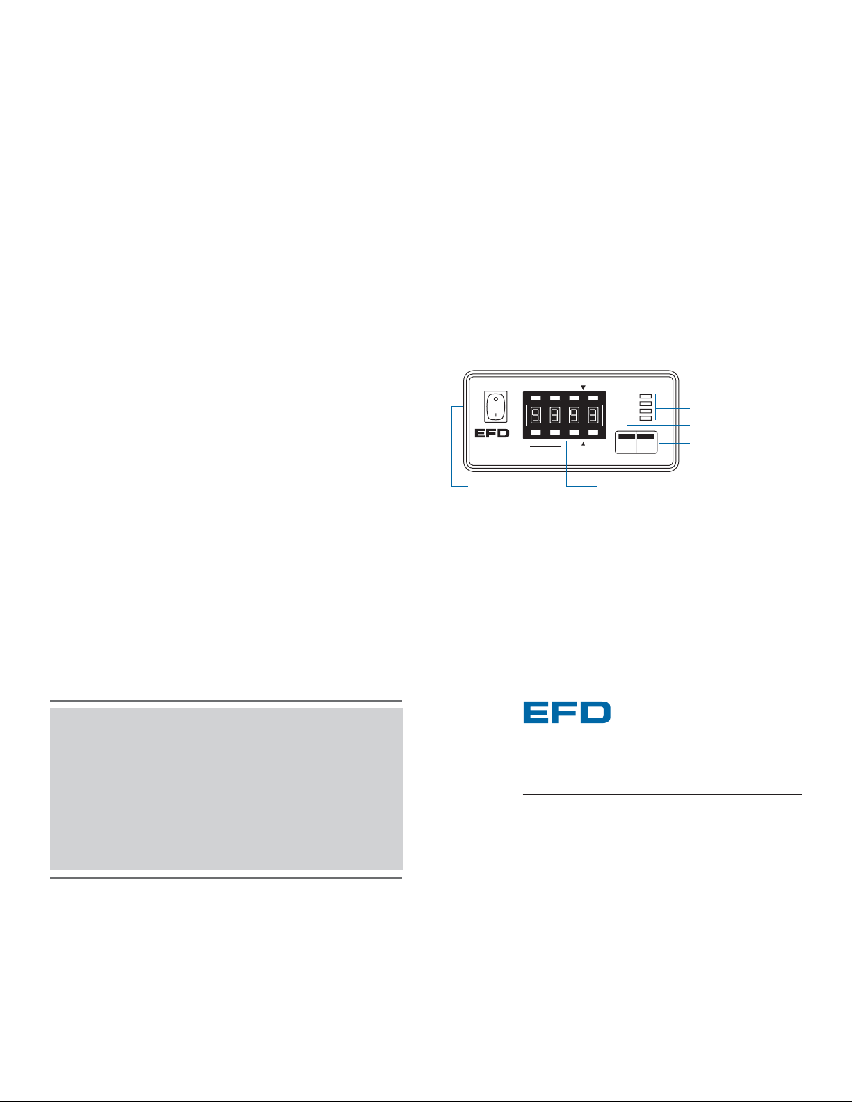
Control Pad
set time
timer bypass
display pressure (psi, bar)
TEACH program
test cycle
purge
Function Indicators
Pressure/Time Toggle
Emergency Stop
Steady
Test
®
A NORDSON COMPANY
VALVEMATE
7000
Rear Panel
air input
power input
(voltage selector)
air output to valve
I/O connector with alarm
output (<60 psi)
connector for
optional foot pedal
Run
Setup Program
®
A NORDSON COMPANY
 Loading...