

Page 1

Introduction
The 725HF Series is simple to use and will operate many
millions of cycles without maintenance.
The unique design of the 725HF Series valve provides a
clean fluid cutoff with pullback for precise fluid application
at high cycle rates.
Each 725HF-SS and 725HF-A valve is shipped with a
dispensing tip adapter, fluid inlet fitting and 5-foot actuating
air hose installed. For high-flow applications, the dispensing
tip adapter can be removed for installation of 1/4 NPT
metal or plastic nozzles.
The 725HF-A is identical to the 725HF-SS, except the
fluid body and cap are acetal copolymer, and the shaft
and the sealing-head screw are Teflon®-coated stainless
steel.
725HF High Flow Series
Dispense Valves
INSTALLATION GUIDE
USA: 800-556-3484 or +1-401-434-1680
Europe: 0800 585733 or +44 (0) 1582 666334
Asia: +86 (21) 5854 2345
technical@efd-inc.com www.efd-inc.com
Electronic pdf files of EFD®manuals are also available at
www.efd-inc.com/manuals.html.
®
A NORDSON COMPANY
supply line
Inlet fitting
Fluid
Control air hose
Air cylinder cap
Air cylinder
Wrench flats
Body cap
Nozzle
Page 2
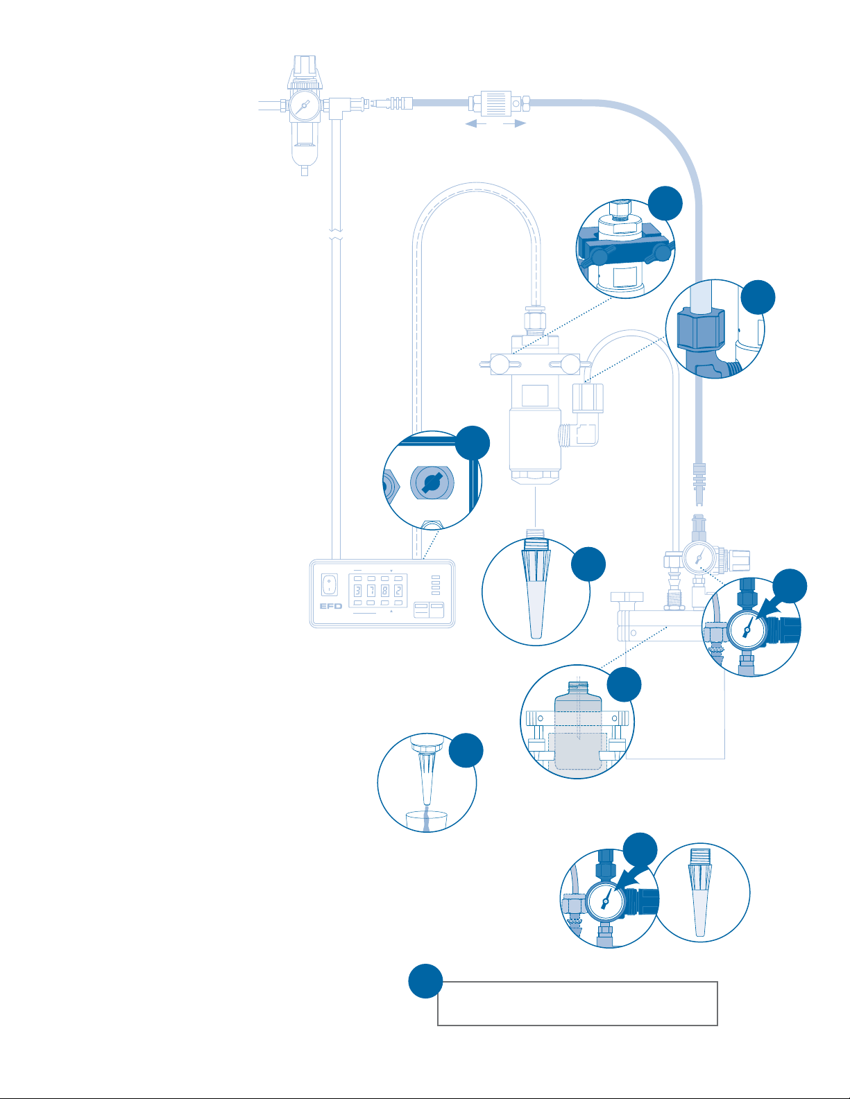
Installation
Set desired deposit size by adjusting valve open
time. Refer to valve controller operating manual.
9
1. Mount valve with an EFD universal valve
mount (#7002VM) or other fixture.
2. Connect the fluid feed hose to the fluid
inlet fitting (#72608P is installed for use
with 3/8” OD tubing and reservoir.
3. Connect valve control air hose to
ValveMate
™
controller (or other pneumatic
switch) used to control valve open time.
4. Install nozzle to the valve output.
5. Fill reservoir by pouring fluid directly into
tank liner or manufacturer’s bottle
placed inside reservoir. Secure cover
prior to setting pressure.
6. Set reservoir pressure, to low for thin
fluids and higher for thick fluids.
7. Place a cup under the dispensing tip
or nozzle and actuate the valve until
fluid lines, valve and dispensing tip are
free of air.
8. Set desired flow rate by adjusting fluid
reservoir or changing dispensing tip or
nozzle.
9. Set desired deposit size by adjusting
valve open time. Refer to valve controller
operating manual.
7
Air Output
Exhaust
Prior to installing this valve, please
read the associated reservoir and
valve controller operating instructions
to become familiar with the operation
of all components of the dispensing
system.
1
6
4
2
5
3
8
To exhaust
To pressurize
A NORDSON COMPANY
®
Steady
Test
Run
Setup Program
Time Set
Clear
Fast Slow
POWER
RUN
SETUP
CYCLE
Fast Slow
Time Set
Pressure
STOP
Time
Purge
Page 3

closed
open
How the Valve Operates
Input air pressure at 70 psi*(4.8 bar)
forces the internal piston ➀➀to move
down, causing the diaphragm seal ➁➁to
deflect and the sealing head
➂➂
to open
and permit fluid flow. When the input air
pressure exhausts, the spring retracts
the piston and the sealing head closes,
stopping the fluid flow and pulling back
a slight amount of fluid.
The primary control of deposit size is the valve open time.
ValveMate Concept
The ValveMate 7000 provides easy
adjustment of valve output for maximum
end-user convenience and efficiency.
Valve open time is the primary control of
deposit size. The 7000 puts push-button
adjustment of valve open time where it
needs to be—at the valve.
Deposit size can be programmed by
pressing the PROGRAM button in the
SETUP mode. This affords an easy
starting point for selecting deposit size.
Note: The EFD Ultra®TT 325 and 525
XYZ automated dispensing systems
have integrated ValveMate controllers
for operating all EFD dispense valves.
➀➀
➁➁
➁➁
➂➂
➂➂
The amount of fluid dispensed will depend
on the time the valve is open, the viscosity
of the fluid, the air pressure in the fluid
reservoir and the dispensing tip size.
Flow rate is a function of reservoir pressure,
tip size and fluid viscosity.
*
For stripes and lines, input air pressure can
be lowered to eliminate opening surge.
www.efd-inc.com technical@efd-inc.com USA 800-556-3484 Europe +44 (0) 1582 666334 Asia +86 (21) 5854 2345
Steady
Test
A NORDSON COMPANY
VALVEMATE
7000
®
Run
Setup Program
Rear Panel
air input
power input
(voltage selector)
air output to valve
I/O connector with alarm
output (<60 psi)
connector for
optional foot pedal
Purge
Time Set
Clear
Fast Slow
Fast Slow
Time Set
POWER
RUN
SETUP
CYCLE
Pressure
STOP
Time
Control Pad
set time
timer bypass
display pressure (psi, bar)
TEACH program
test cycle
purge
reset
Function Indicators
Pressure/Time Toggle
Emergency Stop
Page 4

Specifications
General
Size: 90.1 mm length x 31.1 mm diameter (3.55” x 1.22”)
Valve seal/diaphragm: FDA-approved UHMW* polymer
Air cylinder body: Hard-coated aluminum
Fluid inlet thread: 1/4 NPT female
Output thread: 1/4 NPT female
Air pressure required: 70 to 90 psi (4.8 to 6.2 bar)
Maximum fluid pressure: 100 psi (6.9 bar)
Maximum operating temperature: 43°C (110°F)
725HF-SS
Weight: 295 grams (10.4 oz)
Shaft and sealing head screw: 303 stainless steel
Fluid body and cap: 303 stainless steel
Mounting hole: 5/16-24
725HF-A
Weight: 181 grams (6.4 oz)
Shaft and sealing head screw: Teflon
®
-coated 303 SS
Fluid body and cap: inert acetal copolymer
* Ultra High Molecular Weight
For consistent dispense valve operation and easy adjustment
of valve output, EFD recommends using the ValveMate 7000
controller on all automatic, semi-automatic and benchtop
applications.
The EFD Ultra TT Series positioning systems incorporate
dispensing control into the main system.
Contact the EFD Dispense Valve Systems Group for details.
For EFD sales and service in over 30 countries,
contact EFD or go to www.efd-inc.com/contact
EFD, Inc.
East Providence, RI USA
800-556-3484; +1-401-434-1680 (outside the USA)
info@efd-inc.com www.efd-inc.com
EFD International Inc.
Dunstable, Bedfordshire, UK
0800 585733 or +44 (0) 1582 666334
Ireland 00800 8272 9444
europe@efd-inc.com www.efd-inc.com
EFD, Inc., Asia
China: +86 (21) 5854 2345
china@efd-inc.com www.efd-inc.com/cn
Singapore: +65 6896 9630 sin-mal@efd-inc.com
Teflon is a registered trademark of DuPont.
©2006 Nordson Corporation 725HF-INSTALL-01 v062606
®
A NORDSON COMPANY
 Loading...