

User’s Guide
®
A NORDSON COMPANY
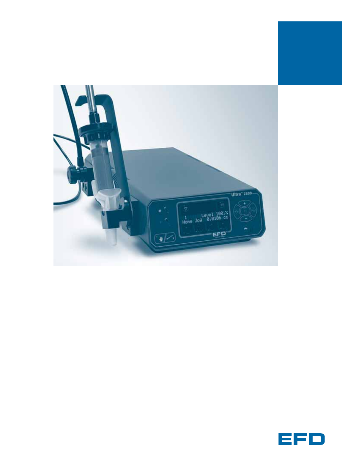
Ultra®2800 Dispensing System
2800-3
3cc syringe barrels
2800-5
5cc syringe barrels
2800-10
10cc syringe barrels
2800-30
30cc syringe barrels
Electronic pdf files of EFD manuals are also available at www.efd-inc.com/manuals.html

The Ultra 2800 Dispensing System uses a patented positive displacement technology to provide
precise, controlled fluid dispensing. This User’s Guide will help you maximize the usefulness of your
new dispensing system.
Please spend a few minutes to become familiar with the controls and features. Follow our
recommended testing procedures. Review the helpful information we have included, which is based
on more than 30 years of industrial dispensing experience.
Most questions you will have are answered in this guide. However, if you need assistance, please do
not hesitate to contact EFD or your authorized EFD distributor.
In the USA, call 800-556-3484 between 8:30 a.m. and 5:30 p.m. Eastern time.
In Europe, call +44 (0) 1582 666334.
In Asia, call +86 (21) 5854 2345.
In all other areas, call your authorized EFD distributor or +1-401-434-1680.
The EFD Pledge
We pledge that you will be completely satisfied with our products. We endeavor to ensure that every
EFD product is produced to our no-compromise quality standards.
If you feel that you are not receiving all the support you require, or if you have any questions or
comments, I invite you to write or call me personally.
Our goal is to build not only the finest equipment and components, but also to build long-term customer
relationships founded on superb quality, service, value and trust.
Peter Lambert, President
Introduction
2

Safety . . . . . . . . . . . . . . . . . . . . . . . . . . . . . . . . . . . . . . . . . . . . . . . . . . . . . . . . . . . . . . 4
Getting Started . . . . . . . . . . . . . . . . . . . . . . . . . . . . . . . . . . . . . . . . . . . . . . . . . . . . . . . . 6
Unpacking the dispenser and activating the warranty
Specifications. . . . . . . . . . . . . . . . . . . . . . . . . . . . . . . . . . . . . . . . . . . . . . . . . . . . . . . . . 7
Operation. . . . . . . . . . . . . . . . . . . . . . . . . . . . . . . . . . . . . . . . . . . . . . . . . . . . . . . . . . . . 8
Features and Controls. . . . . . . . . . . . . . . . . . . . . . . . . . . . . . . . . . . . . . . . . . . . . . . . 9–13
Attaching the Syringe Barrel . . . . . . . . . . . . . . . . . . . . . . . . . . . . . . . . . . . . . . . . . . . . . 14
Removing the syringe barrel . . 14
Program Function . . . . . . . . . . . . . . . . . . . . . . . . . . . . . . . . . . . . . . . . . . . . . . . . . . . . . 15
How to Make a Bead . . . . . . . . . . . . . . . . . . . . . . . . . . . . . . . . . . . . . . . . . . . . . . . . . . 16
Modify Function . . . . . . . . . . . . . . . . . . . . . . . . . . . . . . . . . . . . . . . . . . . . . . . . . . . . . . 17
Operating Tips . . . . . . . . . . . . . . . . . . . . . . . . . . . . . . . . . . . . . . . . . . . . . . . . . . . . . . . 18
Pre-Load Adjustment . . . . . . . . . . . . . . . . . . . . . . . . . . . . . . . . . . . . . . . . . . . . . . . . . . 19
Syringe Barrel Filling . . . . . . . . . . . . . . . . . . . . . . . . . . . . . . . . . . . . . . . . . . . . . . . . . . . 20
Input/Output Connection . . . . . . . . . . . . . . . . . . . . . . . . . . . . . . . . . . . . . . . . . . . . . . . . 21
Troubleshooting . . . . . . . . . . . . . . . . . . . . . . . . . . . . . . . . . . . . . . . . . . . . . . . . . . . . . . 22
Productivity Tools . . . . . . . . . . . . . . . . . . . . . . . . . . . . . . . . . . . . . . . . . . . . . . . . . . . . . 23
Replacement Parts . . . . . . . . . . . . . . . . . . . . . . . . . . . . . . . . . . . . . . . . . . . . . . . . . . . . 24
Warranty . . . . . . . . . . . . . . . . . . . . . . . . . . . . . . . . . . . . . . . . . . . . . . . . . . . . . Back Cover
Contents
3

Safety
4
Introduction
Read and follow these safety instructions. Task- and equipment-specific warnings, cautions and
instructions are included in equipment documentation where appropriate.
Make sure all equipment documentation, including these instructions, is accessible to persons operating or
servicing equipment.
Qualified Personnel
Equipment owners are responsible for making sure that EFD equipment is installed, operated and serviced
by qualified personnel. Qualified personnel are those employees or contractors who are trained to safely
perform their assigned tasks. They are familiar with all relevant safety rules and regulations and are
physically capable of performing their assigned tasks.
Intended Use
Use of EFD equipment in ways other than those described in the documentation supplied with the
equipment may result in injury to persons or damage to property.
Some examples of unintended use of equipment include:
Regulations and Approvals
Make sure all equipment is rated and approved for the environment in which it is used. Any approvals obtained
for EFD equipment will be voided if instructions for installation, operation and service are not followed.
Personal Safety
To prevent injury follow these instructions.
• Do not operate or service equipment unless you are qualified.
• Do not operate equipment unless safety guards, doors or covers are intact and automatic interlocks are
operating properly. Do not bypass or disarm any safety devices.
• Keep clear of moving equipment. Before adjusting or servicing moving equipment, shut off the power
supply and wait until the equipment comes to a complete stop. Lock out power and secure the
equipment to prevent unexpected movement.
• If you receive even a slight electrical shock, shut down all electrical or equipment immediately. Do not
restart the equipment until the problem has been identified and corrected.
• Obtain and read Material Safety Data Sheets (MSDS) for all materials used. Follow the manufacturer’s
instructions for safe handling and use of materials, and use recommended personal protection devices.
• To prevent injury, be aware of less-obvious dangers in the workplace that often cannot be completely
eliminated, such as hot surfaces, sharp edges, energized electrical circuits and moving parts that
cannot be enclosed or otherwise guarded for practical reasons.
• Using incompatible materials
• Making unauthorized modifications
• Removing or bypassing safety guards or
interlocks
• Using incompatible or damaged parts
• Using unapproved auxiliary equipment
• Operating equipment in excess of maximum
ratings
Safety
5
High-Pressure Fluids
High-pressure fluids, unless they are safely contained, are extremely hazardous. Always relieve fluid
pressure before adjusting or servicing high pressure equipment. A jet of high-pressure fluid can cut
like a knife and cause serious bodily injury, amputation, or death. Fluids penetrating the skin can
also cause toxic poisoning.
If you suffer a fluid injection injury, seek medical care immediately. If possible, provide a copy of the
MSDS for the injected fluid to the health-care provider. A copy of the hydraulic fluid used in this unit is
included with this manual.
WARNING: Any injury caused by high pressure liquid can be
serious. If you are injured or even suspect an injury:
• Go to an emergency room immediately.
• Tell the doctor that you suspect an injection injury.
• Show the doctor this note.
• Tell the doctor what kind of material you were dispensing.
Fire Safety
To avoid a fire or explosion, follow these instructions.
• Shut down all equipment immediately if you notice static sparking or arcing. Do not restart the
equipment until the cause has been identified and corrected.
• Do not smoke, weld, grind or use open flames where flammable materials are being used or
stored.
• Provide adequate ventilation to prevent dangerous concentrations of volatile particles or vapors.
Refer to local codes or your material MSDS for guidance.
• Do not disconnect live electrical circuits when working with flammable materials. Shut off
power at a disconnect switch first to prevent sparking.
• Know where emergency stop buttons, shutoff valves and fire extinguishers are located.
• Clean, maintain, test and repair equipment according to the instructions in your equipment
documentation.
• Use only replacement parts that are designed for use with original equipment. Contact your EFD
representative for parts information and advice.
Action in the Event of a Malfunction
If a system or any equipment in a system malfunctions, shut off the system immediately and perform
the following steps:
• Disconnect and lock out system electrical power.
• Slowly unscrew barrel retainer and remove barrel from actuator.
• Identify the reason for the malfunction and correct it before restarting the system.
Disposal
Dispose of equipment and materials used in operation and servicing according to local codes.
MEDICAL ALERT–
AIRLESS SPRAY
WOUNDS:
NOTE TO
PHYSICIAN
Injection in the
skin is a serious
traumatic injury.
It is important to
treat the injury
surgically as soon
as possible.
Do not delay
treatment to
research toxicity.
Toxicity is a
concern with
some exotic
coatings injected
directly into the
bloodstream.

The Ultra 2800 Dispensing System is designed to provide complete process control using a patented
positive displacement technology.
There are four core variables to the system: Deposit Volume, Dispense Rate, Pause and Pullback. To
achieve the ideal deposit size, adjust only one of these variables at a time, in small increments.
Key features include
• Repeatable, precise fluid control
• All electric; no requirement for compressed air
• Programmable Pullback to eliminate oozing
• Menu-driven touch pad
• 100 user-defined memory cells for storing barrel size, deposit volume, dispense rate, pause and
pullback
The Ultra 2800 Dispensing System provides consistent results, regardless of changes in fluid
volume, viscosity or temperature. It is ideal for use with 2-part epoxies and other fluids with
changing viscosities, or where a specific flow rate is needed.
First Steps
1. Unpack the dispenser.
2. For step-by-step setup instructions, see the Ultra 2800 Quick Start Guide.
3. Now is a good time to ACTIVATE your Two Year Warranty. Please follow the instructions in the
enclosed “Welcome” letter to register your warranty online. Or if you prefer, call the appropriate
toll-free number listed below, provide the serial number of your dispensing system and respond
to a few short questions.
In the USA, call 800-556-3484 between 8:30 a.m. and 5:30 p.m. Eastern time.
In Europe, call +44 (0) 1582 666334.
In Asia, call +86 (21) 5854 2345.
In all other areas, call your authorized EFD distributor or +1-401-434-1680.
Getting
Started
6
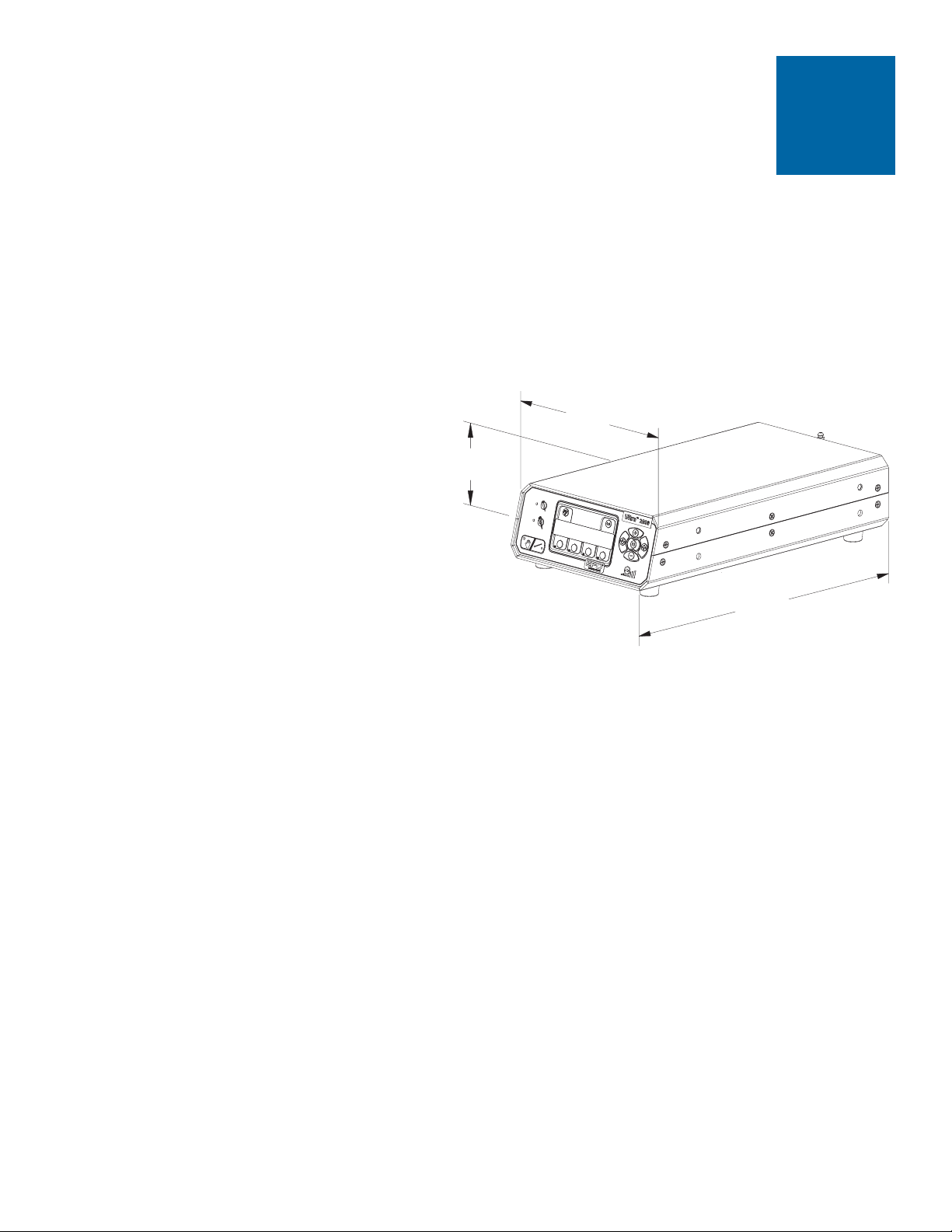
Cabinet size: 18.4 W x 8.1 H x 32.3 D cm (7.25 x 3.18 x 12.73")
Weight: 3.7 kg (8.2 lbs)
Flexible cable assembly length: 1.8 m (6 ft) to end of handset
Flexible cable assembly weight: .113 kg (4 oz)
Flexible cable assembly bend radius: 7.62 cm (3.0")
Internal power supply: Input voltage range, 100-240 VAC
Max inrush current: 50A/264 VAC
Input frequency range: 47-63 Hz
Output voltage: 24 VDC
Output current: 2.5A
Output power: 60W
Fuse rating: 1.0A/250 VAC (EFD part #28139 or equivalent)
Initiate circuit: Foot pedal, Cycle Start button or 5 to 24 VDC signal
Drive motor: 1.8º microstepping, 1,600 steps/rev
Control circuitry: CMOS microprocessor
Interface: Tactile keypad
Hydraulic fluid: Petroleum-based lubricant
Enclosure rating: NEMA 1
Dispense rate: Exceeds 20 cycles per minute
Minimum dispense volume: 0.1 microliters (with 3cc syringe barrel)
Meets or exceeds CE requirements
US Patent No. 6,575,331
Note: Specifications and technical details are subject to change without prior notification.
MSDS for hydraulic fluid enclosed separately. Contact EFD if extra copy is required.
Specifications
7
18.4 cm
7.25"
8.1 cm
3.18"
32.3 cm
12.73"
The Ultra 2800 Dispensing System uses a flexible hydraulic link to transfer linear force from the drive
motor to the syringe barrel. The motor lead screw and drive shaft are also linked mechanically. This
patented link allows the transfer of up to 200 pounds of force from the motor to the assembly fluid.
Once a dispense cycle is complete, a programmed mechanical pullback retracts the plunger,
attached to the EFD piston. The combined action of the plunger with the unit’s Forward steps,
programmed Pause function and Pullback feature creates a consistent deposit and prevents fluid
from oozing.
The bore and stroke of the syringe barrel are used to calculate deposit volume. For example, the
inside diameter of a 5cc syringe barrel measures 1.27 cm. One step moves the plunger 0.00008 cm,
resulting in 0.0001cc of fluid being displaced. With a 3cc barrel, it takes two steps to displace the
same amount of fluid.
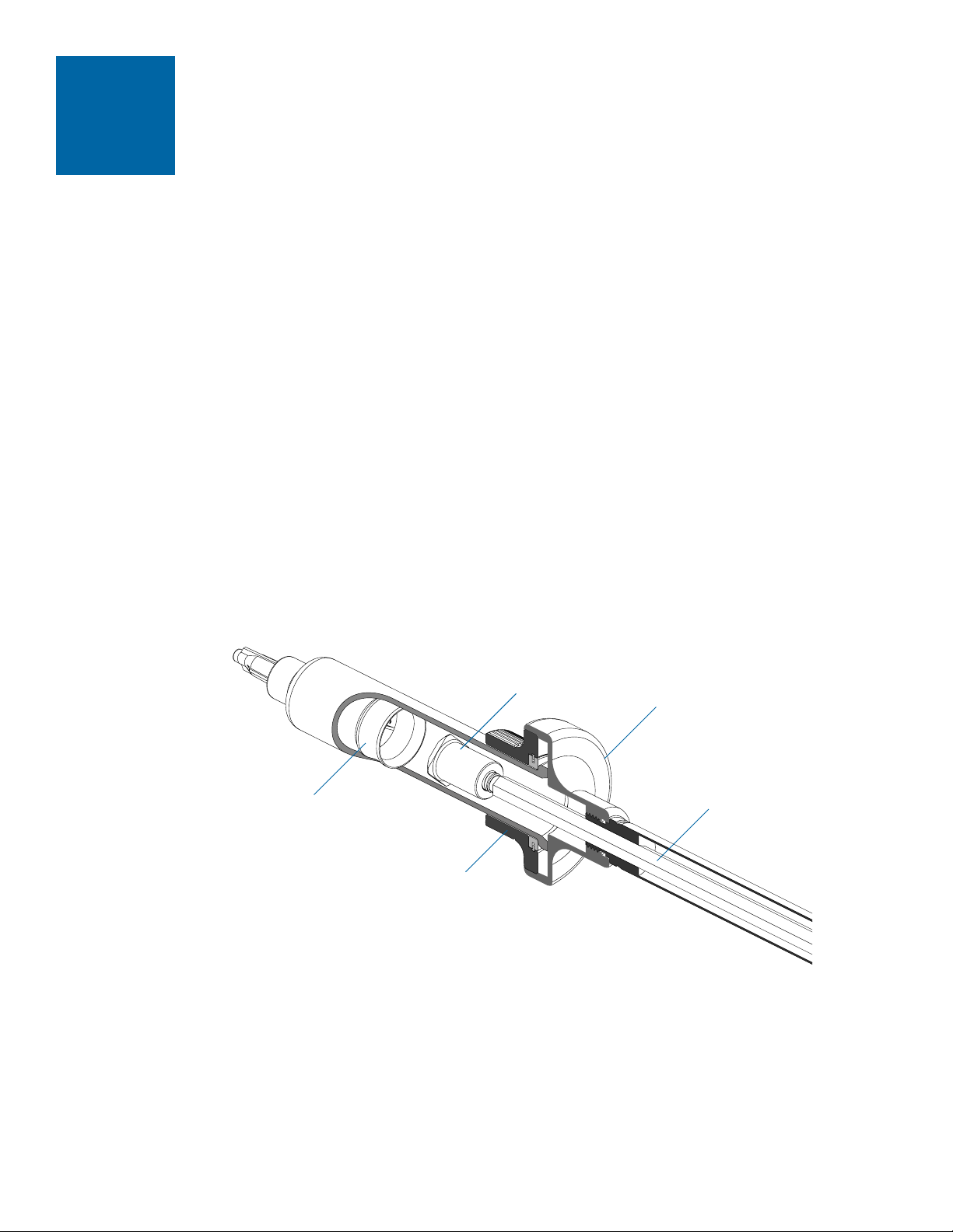
Flexible cable assembly
The force of the stepper motor is transferred to the syringe barrel by a flexible cable assembly.
The plunger, attached at the end of the cable, drives into the EFD piston inside the syringe barrel.
This action forces the fluid out to make the deposit.
8
Adapter
Drive shaft
EFD piston
Plunger
Barrel retainer
Power Input Receptacle
The Ultra 2800 features a universal power supply. It automatically adjusts for input voltages ranging
from 100 VAC to 240 VAC. There is no adjustment required by the user.
Dispenser
Operation
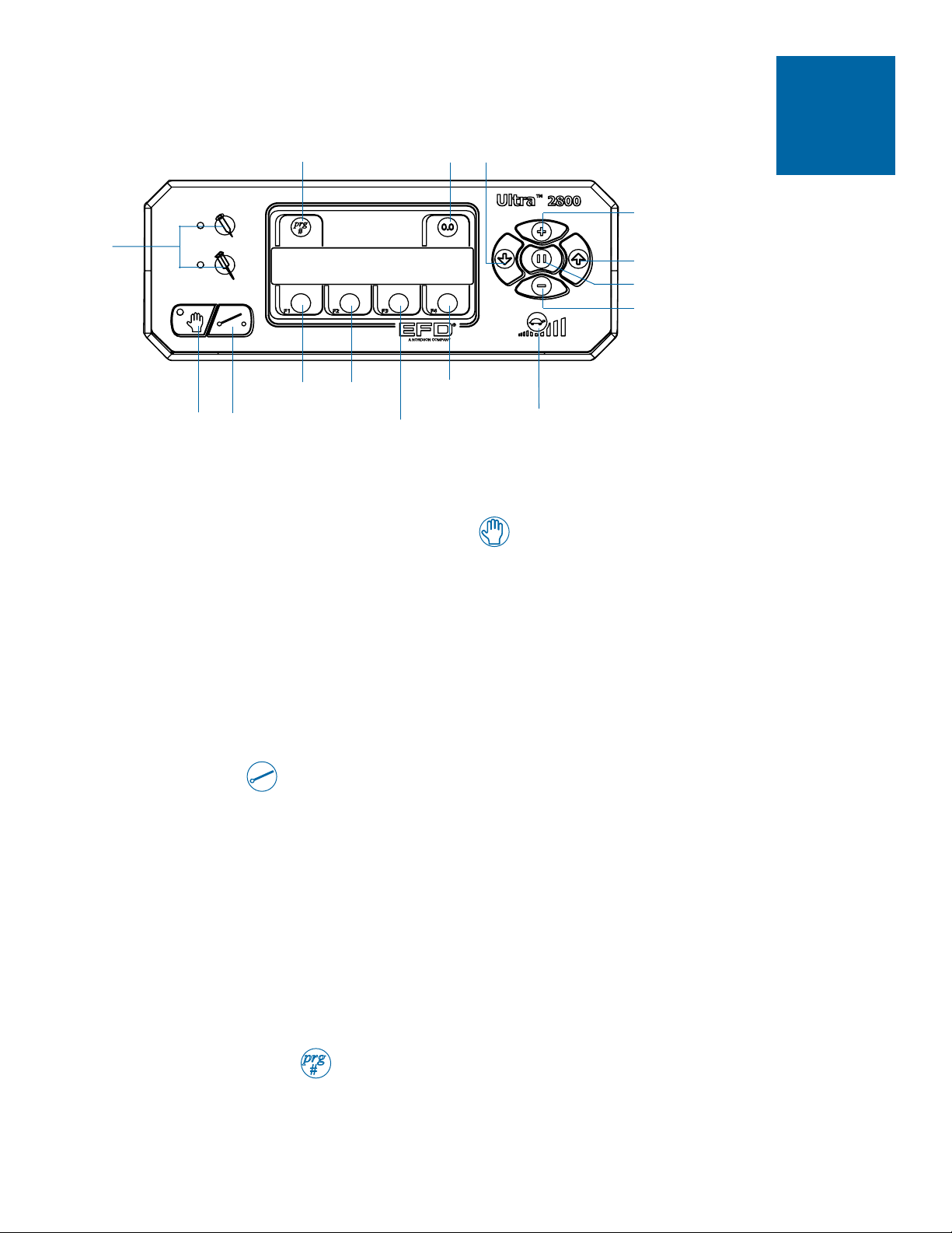
Manual/Programmed Dispense Select
• Each mode allows you to access different features on the menu-driven display. Press the
“hand” icon to change from Manual mode to PROGRAMMED DISPENSE mode.
• In MANUAL mode, you can use the foot pedal to dispense a continuous bead of fluid. You are
in MANUAL mode when the red light next to the “hand” icon is on.
• In PROGRAMMED DISPENSE mode, you can set several variables, including Program Number,
Syringe Barrel Size, Deposit Volume, Dispense Rate, Pause and Pullback. You can also use the
foot pedal or the Cycle Start button to dispense a single dot of fluid. You are in PROGRAMMED
DISPENSE mode when the light next to the “hand” icon is off.
Cycle Start
Cycle Start in PROGRAMMED DISPENSE mode
• In PROGRAMMED DISPENSE mode, pressing the Cycle Start button once will return you to the
Home screen. Pressing it a second time will dispense a single deposit.
• Note: pressing the Cycle Start button accidentally while already in a dispense cycle can abort
your program. Therefore, we recommend that you use the foot pedal (instead of Cycle Start) to
activate the dispense cycle.
Cycle Start in MANUAL mode
• In Manual mode, pressing the Cycle Start button once cancels the Manual selection and returns
you to Programmed Dispense mode and the Home screen.
Program Number
In both PROGRAMMED DISPENSE and MANUAL mode, select the Program Number by pressing
the prg button. The Program Number will flash. Use the (+) or (-) buttons to change or select the
Program Number as needed. For more details, see the Program section on page 15.
Program
number
Reset
Barrel
select
Manual/Program
select
Cycle
start
Home
F1
F2
Jog
F3
Dispense rate &
Shot count/Volume
F4
Reset
shot count
Manual dispense rate
Decrease
Pullback/Back
Increase
Deposit volume/
Forward
Pause
Features &
Controls
9

Barrel Select
In both PROGRAMMED DISPENSE and MANUAL mode, pressing the top Single Barrel Select
button activates the screen for the barrel size menu and pre-set dispense rates.
• Press the F1 button to set barrel size. Use the (+) or (-) buttons to scroll through the various
size options.
• Press the F3 button to set Dispense Rate. Select Low, Medium, or High.
The dual barrel select button is not active.
Reset
In PROGRAMMED DISPENSE mode, press the Reset button to reset a range of variables,
depending on the screen selected. Reset choices include syringe barrel volume level to 100%,
Dispense Volume to 0cc, Pause to 0 ms, Pullback to 0 steps, and Dispense Rate to the lowest
minimum value possible, depending on the selected syringe barrel size. (Note: to reset Shot Count,
use the F4 button.)
In MANUAL mode, the Reset button is not active.
Home (F1)
In both PROGRAMMED DISPENSE and MANUAL mode, pressing the F1 button activates the
“Retract to Home” screen. This step is required to remove the syringe barrel and/or when you want
to prepare the unit for storage or shipping.
• Choose Yes by pressing the F3 button. This will fully retract the plunger.
• Choose No by pressing the F4 button. This will return you to the Home screen.
Jog (F2)
In PROGRAMMED DISPENSE mode, pressing the F2 button activates the Jog screen. Jog allows
you to make small adjustments to the position of the plunger as it extends forward. Press and hold
F2 until the “g” of Jog is highlighted. Use the FORWARD and BACK buttons to move the plunger
slightly in either direction as needed.
In MANUAL mode, the F2 button is not active.
Features &
Controls
10

Shot Count/Deposit Volume (F3)
In PROGRAMMED DISPENSE mode, pressing the F3 button lets you toggle between Shot Count
and Deposit Volume.
• Shot Count displays and tracks the number of deposit cycles. You can reset the Shot Count
display to 0 by pressing the F4 button.
• Deposit Volume displays the current volume programmed in cc’s.
In MANUAL mode, the F3 button is not active.
Other F3 commands:
• From the Retract to Home screen, F3 allows you to select the Yes option.
• After you press the Barrel Select button, F3 allows you to set the Dispense Rate.
• From the Modify screen, F3 allows you to adjust the syringe barrel specification for diameter.
(See MODIFY, page 17.)
F4 Button
In both PROGRAMMED DISPENSE and MANUAL mode, the F4 button is not active until you are in
the screens noted below.
• From the Shot Count screen (F3), the F4 button allows you to reset the Shot Count to 0.
• From the Retract to Home screen (F1), F4 allows you to select the No option.
• From the Modify screen, F4 allows you to adjust the syringe barrel specifications for stroke.
(See MODIFY, page 17.)
Deposit Volume/Forward
In PROGRAMMED DISPENSE mode, press the Forward button to activate the Deposit Volume
screen. Use the (+) or (-) buttons to change the deposit volume as needed.
Deposit volume, measured in cc’s, is automatically linked to Forward steps in the Ultra 2800 stepper
motor. When you increase the cc setting, it automatically increases the number of Forward steps.
The maximum number of Forward steps is 65,534.
Deposit Volume is displayed when you press the F3/Shot Volume button.
In MANUAL mode, pressing and holding the Forward button will extend the plunger from the cable
assembly.
Features &
Controls
11

Pause
The Pause function “pauses” the action of the plunger during a dispense cycle, acts as a settling
period and allows the relief of back pressure between Forward and Pullback steps. Pause is helpful
when you are dispensing a large amount of material with a very small tip. In most cases you will not
need to use the Pause function.
In PROGRAMMED DISPENSE mode, press the Pause button to insert an end-of-cycle pause. Use
the (+) or (-) buttons to set the Pause time.
In MANUAL mode, the Pause button is not active.
• Pause is measured in milliseconds. The maximum Pause is 60,000 ms (one minute).
• The default setting for Pause is 0 ms.
Pullback/Back
Pullback sets the number of steps that the plunger will retract into the cable assembly, in
preparation for the next dispense cycle. Be conservative when setting the Pullback. With thick fluids,
too much Pullback can disengage the plunger from the piston. With thin fluids, excess Pullback can
introduce air into the syringe barrel.
In PROGRAMMED DISPENSE mode, press the Back button to activate the Pullback screen. Use
the (+) or (-) buttons to change the number of Pullback steps as needed.
• Use Pullback to eliminate dripping and oozing. We recommend a minimum Pullback of 200
steps for low viscosity fluids.
• For thicker fluids, set the Pullback to 300 steps or more.
• In general, adjust Pullback in small increments of 50 steps at a time for best results. Press the
foot pedal to dispense, and visually check the deposit. Adjust Pullback again if necessary.
When setup is correct, there should be no oozing or dripping.
• The maximum number of Pullback steps is 20,000.
• The default setting for Pullback is 200 steps.
In MANUAL mode, press and hold the Back button to manually retract the plunger as needed.
Features &
Controls
12

Dispense Rate
In both PROGRAMMED DISPENSE and MANUAL mode, pressing the Turtle button allows you to
manually set the Dispense Rate. Use the (+) or (-) buttons to change the speed manually if needed.
In most cases, however, we recommend that you simply use one of the preset Dispense Rates.
• Press the Single Barrel Select button.
• Press F3 to access the Dispense Rate options.
• Select Low, Medium or High.
Dispense Rate is based on cc’s per second. For best results, use the slowest Dispense Rate practical
to your application. In general, start with the preset default rate of Medium. Slower dispense rates
give you better repeatability, since they create less fluid compression. This helps prevent oozing.
Increase and Decrease
In both PROGRAMMED DISPENSE and MANUAL mode, press the (+) or (-) button to change a
number of variables, including Program Number, Deposit Volume, Dispense Rate, Pause milliseconds,
Pullback steps and more.
When the (+) or (-) buttons are pressed briefly, the settings will adjust slowly. When the (+) or (-)
buttons are pressed and held, the settings will adjust faster.
Features &
Controls
13
Back Panel
Connect foot pedal
Power Input
On/Off
Connect I/O

Attach Barrel/Purge Tip
Note: Stay in MANUAL mode for all steps to attach the barrel.
1. Unscrew and remove the barrel retainer from the adapter.
2. Put a tip cap on the syringe barrel and hold barrel next to the flexible cable assembly.
3. From MANUAL mode (hand icon light on), advance the plunger by pressing the Forward button,
just until the plunger reaches past the piston.
4. By hand, insert the plunger into the barrel, pressing it snugly into the piston.
5. Press the Pullback button to retract barrel, until there is just a small gap between barrel and
adapter.
6. Slide barrel retainer over the barrel and thread one turn onto the adapter.
7. Replace tip cap with dispense tip. Tighten barrel retainer.
8. Still in MANUAL mode, press the foot pedal to purge dispense tip. Press until fluid almost fills
the tip and dispenses. Be sure not to overfill the tip since this results in excess back pressure,
which can cause oozing.
Note: See the handout provided with your Ultra 2800 dispenser, Syringe Barrel Attachment
Guide, for simple, step-by-step instructions.
Removing the syringe barrel
1. Press F1 to get the Retract to Home screen. Select Yes. This will retract the plunger into the
cable assembly.
2. Unscrew the barrel retainer from the adapter.
3. Slide the syringe barrel off the plunger.
4. Discard the barrel, or if storing for later use, replace the dispense tip with a tip cap.
5. Screw the barrel retainer back onto the adapter.
Attaching
the Syringe
Barrel
14
Barrel retainer
Adapter
Plunger
Piston
Flexible cable assembly without the syringe barrel
Flexible cable assembly with the syringe barrel
Caution: When the
plunger fits into
the piston, stop
pressing Forward.
If you continue,
excess pressure
can build inside
the barrel and
may cause it to
burst, resulting in
serious injury.
Plunger
Adapter

1
30cc
Shot
Steps
0.0500cc
160
Program
number
Barrel
select
Hand icon
Back
Forward
Pause
Program
Function
15
The Ultra 2800 Dispensing System offers 100 user-defined memory programs, ranging from 0-99.
The programs store the following information.
• Syringe barrel size
• Deposit volume
• Dispense rate
• Pause
• Pullback
Follow these steps to define a program
1. Select PROGRAMMED DISPENSE mode. (Press “hand” icon so red light is off.)
2. Press prg to highlight the program number. Use the (+) or (-) buttons to assign or select the
program number.
3. Press the icon for Single Barrel Select. Set Dispense Rate from this screen by pressing F3 for
Rate, then selecting Medium.
4. Select Deposit Volume by pressing the FORWARD button. Use the (+) or (-) buttons to set
volume.
5. Select Pullback by pressing the BACK button. Use the (+) or (-) buttons to set Pullback.
6. Press the foot pedal once to return to the Home screen. The settings are automatically saved.
7. Press the foot pedal again to dispense the first deposit.

To deposit a continuous bead of fluid, instead of a single dot, follow these steps.
1. Select PROGRAMMED DISPENSE mode. (Press “hand” icon so red light is off.)
2. Press Forward and use (+) or (-) buttons to set Dispense Volume to lowest setting.
3. As a beginning point, keep Pause set to 0 ms and Pullback at 200 steps, then adjust as needed
to eliminate drooling.
4. For best results, set Dispense Rate to the preset of Lo, to minimize back pressure in the syringe
barrel. (Press Single Barrel Select button, then Rate, then Lo.)
5. Select MANUAL mode. (Press “hand” icon so red light is on.)
6. Press and hold the foot pedal until the required amount is dispensed. (Note: the Cycle Start
button is not active in Manual mode, so use the foot pedal to activate the dispense cycle.)
1
10cc
Shot
Steps
0.0001cc
1
Forward
Hand icon
16
How to
Make a
Bead

The Ultra Dispensing System includes pre-set specifications based on industry-standard EFD
syringe barrel dimensions. In most cases, you will want to use these pre-set specifications.
However, you have the option to adjust the settings with the Modify function.
Follow these steps to use the Modify function
1. From either the PROGRAMMED DISPENSE mode or the MANUAL mode, press the Single
Barrel Select button. The MOD (Modify) option will appear.
2. If needed, press F1 to highlight the syringe barrel size. Use the (+) or (-) buttons to select the
correct barrel size — for example, 3cc, 5cc, 10cc, or 30cc.
3. Press F4. This activates the Modify screen.
4. Press F3 to highlight the specifications for the diameter of the syringe barrel. This is
displayed in centimeters. The settings will vary according to the syringe barrel size you have
selected. Use the (+) or (-) buttons to adjust as needed.
5. Press F4 to highlight the specifications for the stroke of the syringe barrel, also listed in
centimeters. Again, the settings will vary depending on the syringe barrel size you have
selected. Use the (+) or (-) buttons to adjust as needed.
Note: The stroke should reflect the distance the EFD piston will travel to dispense
all of the fluid in the syringe barrel. For example, if the barrel is loaded half-full, a certain
stroke length (measured in centimeters) will be required to empty it. By adjusting the stroke
for a specific barrel fill level, you will ensure that the “Level” display on the Home screen
provides an accurate reading.
6. When finished, press the foot pedal once to return to the Home screen.
1
30cc
2.265
Dia
7.60
Strk
Barrel
select
F1/Button
Modify
Function
Modify
Function
17

Helpful Hints
• Faster dispense rates require more Pullback steps. That’s because you are putting more
pressure on the fluid, creating compression inside the syringe. For best results, use the preset
default dispense rate of Medium.
• If you are making small deposits, you are likely creating a lot of pressure trying to force the fluid
through a small dispense tip. Begin with the largest tip practical to your application, with a slow
dispense rate. Depending on how thick your fluid is, you may also need to increase Pullback to
relieve back pressure in the syringe barrel.
• Changing the dispense rate changes the deposit size. The Ultra 2800 provides a metered
deposit based on Forward steps at a specific dispense rate. When you change the dispense
rate, the deposit size also changes, even though the number of Forward steps remains the
same. For example, 25 Forward steps at the high dispense rate produces a smaller deposit than
25 Forward steps at the low rate. That’s because the slower rate gives the fluid more time to
dispense, while the faster rate compresses the fluid and restricts the flow path. For optimum
consistency, stay at the same dispense rate once you have stabilized your deposit settings.
Setting up the First Shot
• Go through the steps outlined in the Ultra 2800 Quick Start Guide to establish your initial
deposit. Work first with the EFD test material, included with your dispensing kit.
• Check the Ultra 2800 Settings Grid for recommended settings, including Forward steps, Pause,
Dispense Rate and Pullback. The grid is included in your dispensing kit.
• Keep your Pullback setting low to reduce the risk of introducing air into your syringe barrel.
• Experiment with different values for each variable. Change only one value at a time and allow
the deposit to stabilize before adjusting or changing another value.
Components
• Always use new EFD barrels and tips. Carefully dispose of after use. This procedure ensures
maximum cleanliness, prevents contamination and provides proper safety.
• You must use a piston with the Ultra 2800. Besides being required to connect with the plunger,
the piston makes barrel loading, dispensing and fluid handling cleaner, safer and more accurate.
• Use the largest tip size possible. Smaller tips require more pressure, which can compress the
fluid and cause oozing, and more time. For best results when working with thick fluids, use EFD
tapered tips. Tapered tips are specially designed to reduce the amount of pressure needed and
are available in a range of sizes. They also help prevent drooling and oozing.
Cycle Start & Abort
The Cycle Start button serves the same purpose as the foot pedal. Pressing either of these once will
return you to Home. However, pressing the Cycle Start button twice can abort your program. Therefore
we recommend that you use the foot pedal to dispense from Programmed mode. A dispense cycle
can be stopped at any time by pressing the Cycle Start button.
Operating
Tips
18

The pre-load on the cable within the flexible cable assembly is preset at the factory. However, over
time the cable may stretch slightly causing a change in performance. The pre-load adjustment block
allows the user to make corrections to the pre-load due to cable stretch. If this happens, turn the
pre-load plug clockwise to readjust the hex shaft to the 1/8" (3.2 mm) to 3/8" (9.5 mm) pre-load
setting range. Do not exceed the 3/8" (9.5 mm) pre-load limit as damage to the unit may result.
The pre-load adjustment block can compensate for approximately 1.5cc’s of hydraulic fluid volume.
However, only a small portion of this volume should ever need to be used. In addition, the pre-load
typically needs to be adjusted just once during the early operation of the unit, and depending on use,
may never be required.
Pre-load adjustment block
(view from underneath)
Pre-load adjustment plug
Follow these steps to make the adjustment
1. Turn power off and detach power cord.
2. Turn unit over.
3. Use slotted screwdriver to turn plug clockwise.
4. Turn until the actuator extends to the 1/8" pre-load dimension, as shown in the figure below.
1/8" (3.2 mm) to 3/8" (9.5 mm) pre-load dimension
Pre-Load
Adjustment
19

Avoid air in the syringe barrel
Air in the fluid is a critical issue with the Ultra 2800 Dispensing System. It can create problems with
inconsistent deposits and drooling. For best results, use an EFD barrel filling station (see below), or
bottom fill the syringe barrel. Simply insert the red piston and push it all the way inside the barrel,
flush to the dispense tip. Then fill through the tip, pushing the piston down as the fluid enters. This
prevents air from entering the syringe barrel.
If needed, eliminate air in the syringe barrel by using centrifuge or a vacuum chamber.
If the fluid being dispensed is pourable, attach an orange tip cap to the syringe barrel and pour the
fluid in. Insert the piston and carefully press it down until it contacts the fluid. The syringe barrel is
now ready for use.
If the fluid is thick or non-leveling, it
can be spooned into the barrel with a
spatula. Or, if the fluid comes packed
in a 1/10 gallon cartridge, the barrel
can be loaded with a caulking gun.
After loading, press in the piston to
move the fluid to the bottom of the
barrel and to remove trapped air.
Caution: Do not completely fill syringe
barrels. The optimum fill is a
maximum 2/3 of the barrel capacity.
If you are working with assembly fluids
with a short pot life, you may want to
fill to 1/2 of the syringe barrel.
EFD offers productive, air-free
alternatives to traditional barrel loading methods. Here are a few suggestions that can help keep the
work area clean, save time and reduce the chance of entrapped air in the fluid.
1. The EFD #8000BF Series automatic syringe filler provides consistent filling for all types of
nonpourable assembly fluids. It features built-in flow controls to prevent spillage and air
entrapment.
2. If you receive frozen epoxies or other fluids in medical type syringes with a manual plunger,
request the EFD luer-to-luer fitting #2160 to transfer the material from the original syringe to
the EFD syringe barrel.
3. Another option is the EFD #920BL barrel loader. Pack the fluid into the 12-ounce cartridge.
Place the pre-filled cartridge into the barrel loader. Using air pressure, the barrel loader fills the
syringe barrel (with piston) from the bottom up.
4. If the fluid comes prepackaged in a 1/10 gallon (300 ml) caulking type cartridge, use the EFD
#940BL barrel loader.
For additional assistance please contact an EFD Fluid Application Specialist.
Fill procedure for thick fluids
(shown: caulking gun)
2/3 maximum fill
2/3
maximum
fill
Piston
Fill procedure for pourable fluids
Syringe
Barrel
Filling
20

Input/Output
Connection
21
Voltage Initiate Circuit
The Ultra 2800 workstation may be initiated with a 5 to 24 VDC signal across pins 1 and 2. These
two input pins are current driven and optically isolated. From Programmed Dispense mode, this
signal can be momentary (no less than 0.01 seconds) or maintained. In this mode, a new dispense
cycle begins once the 5 to 24 VDC signal is removed and then applied again.
When this input circuit is activated in Manual mode, a continuous bead is dispensed until the signal
is removed.
Mechanical Contact Initiate
The Ultra 2800 can be initiated via the closure of mechanical contacts such as a relay or switch
using pins 7 and 8. The timing and actuation rules for the contact closure input are identical to the
voltage initiate input description.
End-of-Cycle Feedback Circuit
Upon completion of a dispense cycle, a solid-state switch closes and remains closed until the next
dispense cycle. This circuit is normally closed when a dispense cycle is not active. Pins 3 and 4 of
this circuit can be used to signal back to a host computer, start another device in sequence or
initiate other operations that need to be tied into the completion of the dispense cycle.
The circuit is an optically isolated transistor output designed to operate between 5 to 24 VDC,
100mA maximum.
Pin Function
1. Voltage initiate +, 5-24 VDC (22mA at 24 VDC)
2. Voltage initiate -
3. End-of-cycle feedback output +, 5-24 VDC (100mA maximum)
4. End-of-cycle feedback output -
5. 24 VDC supply + (100mA maximum)
6. 24 VDC supply – (ground)
7. Contact closure +, 10mA
8. Contact closure – (ground)
Notes
1. An 8-pin DIN connector and cable assembly is available. Order EFD part #2446.
2. 2800 operation is identical for dispense initiation from I/O inputs or the foot pedal.
3. Pins 6 & 8 of the I/O connector are internally connected to signal ground.
2
813
76
54

If you encounter a problem that you cannot readily solve, call EFD.
Trouble Possible cause and correction
No power Check the fuses and replace as needed. Follow these steps:
1. Disconnect the power to the unit prior to performing this service.
2. Locate the power entry module on the lower left corner of the rear panel.
3. If the electrical cord is still connected to the back of the unit, remove it now.
4. There is a small vertical slot just to the right of the red window on the power
entry module. Insert a small screwdriver in the slot to pry latch open.
Door swings open to the left.
5. Pull out the red fuse tray. Note the location and orientation of the fuses.
6. Pull both fuses out of the fuse tray and discard.
7. Replace both with 1.0A/250 VAC 5x20 mm fuses (EFD part #28139 or
equivalent). Orient the fuses in the same manner as the fuses that were removed.
8. Insert fuse tray back into power module, close fuse door and reconnect power.
Blow by If you are dispensing a watery-thin fluid, request the EFD yellow wiper piston,
available for the Ultra 2800-30 model only. Specify EFD part # A678-B.
Oozing 1. There is too much fluid compression in the syringe barrel. Change to a fresh
dispense tip and start over. If needed, switch a slower dispense rate.
2. The plunger has become disengaged from the piston. To check, unscrew the
retainer from the adapter and turn the syringe barrel upside down. If the syringe
barrel falls off, the plunger is disengaged. See the handout, “Syringe Barrel
Attachment Guide,” for step-by-step instructions on how to properly engage the
plunger and piston.
Inconsistent 1. There is air in the syringe barrel, either entering the barrel during filling, or from
shot size excessive Pullback. Eliminate air from the barrel, or adjust the Pullback.
2. The Dispense Rate may be too fast for the combination of fluid viscosity and
dispense tip. Reduce the Dispense Rate.
3. The plunger is fouled. Remove the syringe and clean as needed. Also, check
dispensing tip, barrel and material for possible clogging. For best results,
change the dispense tip.
4. You may need to adjust the pre-load adjustment block. See page 19.
Dispense Rate If nothing seems to happen when you press the (+) or (-) button to manually adjust
does not adjust the Dispense Rate, the rate may already be set to a very low speed. Try switching to
the preset default for Medium.
Service The interior mechanics of the Ultra 2800 system are not field serviceable.
Attempting to repair or service the unit by removing the enclosure cover voids
factory warranty. Please contact your EFD service representative for assistance.
Troubleshoot
22

Choose from several optional productivity tools to maximize your Ultra 2800
dispensing kit.
Barrel Hand Grip
Ergonomic hand grip is available for the 2800-30 model only and easily
holds 30cc syringe barrels. Specify EFD part #2441.
Safety Shield
Large, acrylic shield mounts on a flexible arm to either side of the Ultra
2800 cabinet and provides splash guard protection when adhesives and
toxic fluids are used. Specify EFD part #2436 plus the assembly mount
(#2800AM).
Magnifying Lens
1.7x magnification ensures more accurate deposit placement, improves
repeatability and reduces operator strain. Mounts to either side of the
Ultra 2800 cabinet. Specify EFD part #2442 plus the assembly mount
(#2800AM).
Syringe Barrel Production Stand
Holds syringe barrel in a fixed position for bringing the production part to
the dispense tip. Specify EFD part #2856.
Productivity
Tools
23

Replacement
Parts
24
Part # Description
Barrel/Piston Sets
5109CPD-B 3cc BP Kits Clr/Red (50)
5110CPD-B 5cc BP Kits Clr/Red (40)
5111CPD-B 10cc BP Kits Clr/Red (30)
5112CPD-B 30cc BP Kits Clr/Red (20)
5109LBPD-B 3cc BP Kits LB/Red (50)
5110LBPD-B 5cc BP Kits LB/Red (40)
5111LBPD-B 10cc BP Kits LB/Red (30)
5112LBPD-B 30cc BP Kits LB/Red (20)
Pistons
5109PDP-B 3cc red pistons (50)
5110PDP-B 5cc red pistons (40)
5111PDP-B 10cc red pistons (30)
5112PDP-B 30cc red pistons (20)
A678-B 30cc yellow wiper pistons (20)

Part # Description
Flexible Cable Assembly
2800P-3 3cc plunger
2800P-5 5cc plunger
2800P-10 10cc plunger
2800P-30 30cc plunger
2800R-3 3cc retainer
2800R-5 5cc retainer
2800R-10 10cc retainer
2800R-30 30cc retainer
2800A 3/5/10cc adapter
2800A-30 30cc adapter
Replacement Parts
2422 Omnidirectional foot pedal
2800PS-KIT Power Supply Kit
2800CL-KIT Cylinder Kit
2800FPL-KIT Front Panel Kit,-3cc/5cc
2800FPH-KIT Front Panel Kit,-10cc/30cc
2800CPU-KIT Microprocessor Kit
1000RTM-3 (-5, -10, -30) Red test material with red piston
Productivity Tools
2427-B Replacement sleeve/5 pk
2436 Safety Shield
2441 Barrel Hand Grip (for 2800-30 only)
2442 Magnifying Lens
2446 8-pin Connector Assembly
2856 Syringe Barrel Production Stand
2800AM Accessory Mount
2800BH Syringe Barrel Holder
2800CG Cable Guide Holder
IMPORTANT SAFETY NOTE: To accommodate smaller syringe barrels,
the Ultra 2800-3 and 2800-5 systems use a stepped-down motor.
Do not use 3cc or 5cc replacement parts or components with
a 2800-10 or 2800-30 system.
Replacement
Parts
25

Notes
26

Notes
27

EFD Two Year Limited Warranty
This EFD dispenser is warranted to the original end user for two years from date of purchase.
Within the period of this warranty, EFD will repair or replace any defective component, or the
entire dispenser at EFD’s option, on authorized return of the part or the complete dispenser,
prepaid to the factory.
In no event shall any liability or obligation of EFD arising from this warranty exceed the purchase
price of the equipment. Before using, user shall determine the suitability of the product for its
intended use, and user assumes all risk and liability whatsoever in connection therewith.
EFD makes no warranty whatsoever of merchantability or fitness for a particular purpose.
In no event shall EFD be liable for incidental or consequential damages.
To register your warranty in the USA, please call 800-828-3331 within 30 days, or go to
www.efd-inc.com/warranty/two-2800.
©2006 Nordson Corporation 2800-MAN-01 v062606
This equipment is regulated by the European Union under WEEE Directive (2002/96/EC).
See www.efd-inc.com for information about how to properly dispose of this equipment.
For EFD sales and service in over 30 countries,
contact EFD or go to www.efd-inc.com/contact
EFD, Inc.
East Providence, RI USA
800-556-3484; +1-401-434-1680 (outside the USA)
info@efd-inc.com www.efd-inc.com
EFD International Inc.
Dunstable, Bedfordshire, UK
0800 585733 or +44 (0) 1582 666334
Ireland 00800 8272 9444
europe@efd-inc.com www.efd-inc.com
EFD, Inc., Asia
China: +86 (21) 5854 2345
china@efd-inc.com www.efd-inc.com/cn
Singapore: +65 6896 9630 sin-mal@efd-inc.com
A NORDSON COMPANY
 Loading...