


 Loading...
Data Power Solutions
Installation Guide
Issue: |
IPN 997-00012-41D |
Issue Date: |
December 2006 |
Eaton Corporation
Telecommunications Solutions Division
www.powerware.com
DCinfo@eaton.com
Eaton Corporation disclaims any liability for direct, indirect, incidental, special or consequential damages arising out of the application or use of any information contained in this document. The foregoing disclaimer applies to damages or personal injury, property damage, loss of operation, loss of profits, loss of product or loss of time, whether incurred by the purchaser, the purchaser’s employees or third party.
Information in this document does not constitute a warranty, representation or guarantee concerning the suitability or performance of Powerware products. No such warranty, representation or guarantee is expressed or implied.
Information contained in this document is subject to change without further notice.
Powerware and DCTools are trade names, trademarks, and/or service marks of Eaton Power Quality Corporation or its subsidiaries and affiliates. Unless otherwise noted, brands, product names, trademarks or registered trademarks are the property of their respective holders.
Subject to the right to use its equipment, Eaton Corporation does not convey any right, title or interest in its intellectual property, including, without limitation, its patents, copyrights and know-how.
No part of this document may be reproduced or transmitted in any form, by any means or for any purpose other than the Purchaser’s personal use, without the express written permission of Eaton Corporation.
Copyright © 2005-2006 Eaton Corporation
All Rights Reserved

.
About This Guide
Purpose
This guide provides instructions to correctly install, commission and operate Data Power Solutions.
Audience
This guide is intended for use by IT professionals who have a sound working knowledge of safe working practices.
Scope
This guide covers installation, commissioning and operation of Data Power Solutions, controlled by SM45 supervisory modules.
It does not cover:
•Installation and characterization of batteries.
•Changing the pre-configured configuration values. For full details on changing the preconfigured configuration values, refer to the SM45 Front Panel Menu Structure (on the inside back cover) or DCTools online help.
Related Information
DCTools Online Help
Application Note AN0080: Ventilation of VRLA Batteries
Reporting Problems with This Guide
Please use the fax or email addresses below to report any problems you find in this guide. Powerware DC Marketing Services
FAX: |
++64 3 343 5660 |
EMAIL: |
DCMarketingNZ@eaton.com |
Copyright © 2005-2006 Eaton Corporation. All Rights Reserved.
IPN 997-00012-41D December 2006
i

About This Guide
For Further Information and Technical Assistance
Eaton recognizes the need to keep you informed about the availability of current product information.
For up-to-date product information and a complete listing of worldwide sales offices, visit the Powerware website at: http://www.powerware.com
For comprehensive product data sheets and application notes please contact your local Powerware DC product representative or email: DCinfo@eaton.com
For technical assistance, contact your local Powerware DC product representative in the first instance, alternatively phone (++64) 3 343-7448 or email CustomerServiceNZ@eaton.com
ii
Copyright © 2005-2006 Eaton Corporation. All Rights Reserved.
IPN 997-00012-41D December 2006

.
Table of Contents
About This Guide
|
Purpose...................................................................................................................................... |
i |
|
Audience ................................................................................................................................... |
i |
|
Scope .......................................................................................................................................... |
i |
|
Related Information................................................................................................................. |
i |
|
Reporting Problems with This Guide.................................................................................... |
i |
|
For Further Information and Technical Assistance............................................................ |
ii |
Chapter 1 |
General Description |
|
|
Overview............................................................................................................................... |
1-1 |
|
Data Power Solutions Product Range ............................................................................... |
1-2 |
|
APS3-05X (Rack-Mounted Versions)........................................................................................ |
1-3 |
|
APS3-06X (Desktop Versions) ................................................................................................... |
1-4 |
|
APS6-05X (Rack-Mounted Versions)........................................................................................ |
1-5 |
|
Access Power Rectifiers....................................................................................................... |
1-6 |
|
SM45 Supervisory Module ................................................................................................. |
1-7 |
|
Low Voltage Disconnect (if applicable) ............................................................................ |
1-8 |
Chapter 2 |
Pre-Installation |
|
|
Overview............................................................................................................................... |
2-1 |
|
Warnings ............................................................................................................................... |
2-2 |
|
Inspecting the Equipment and Reporting Damage......................................................... |
2-6 |
Chapter 3 |
Installation |
|
|
Overview............................................................................................................................... |
3-1 |
|
Mounting the Power System .............................................................................................. |
3-2 |
|
DC Installation Practices ..................................................................................................... |
3-3 |
|
Connecting the DC Load Cables........................................................................................ |
3-3 |
|
APS3-05X and APS6-05X (Rack-Mounted Versions).............................................................. |
3-4 |
|
APS3-06X (Desktop Versions) ................................................................................................... |
3-5 |
|
Installing the External Batteries (if applicable)................................................................ |
3-7 |
|
Connecting the Battery Cables (if applicable).................................................................. |
3-8 |
|
Installing the Battery Temperature Sensor (if batteries are fitted).............................. |
3-10 |
|
Connecting the Power System to the AC Supply .......................................................... |
3-12 |
Chapter 4 |
Commissioning |
|
|
Overview............................................................................................................................... |
4-1 |
|
Inserting the Access Power Rectifiers ............................................................................... |
4-2 |
|
Pre-Power-Up Check........................................................................................................... |
4-3 |
|
Applying AC Power ............................................................................................................ |
4-4 |
|
Configuring the Power System for Operation ................................................................. |
4-4 |
|
Using the Front Panel Keypad .................................................................................................. |
4-4 |
|
Using DCTools ............................................................................................................................ |
4-5 |
|
Applying DC Power to the Load ....................................................................................... |
4-8 |
Copyright © 2005-2006 Eaton Corporation. All Rights Reserved.
IPN 997-00012-41D December 2006
iii

Table of Contents
Chapter 5 |
Operations |
|
|
Overview............................................................................................................................... |
5-1 |
|
About the SM45 Front Panel .............................................................................................. |
5-2 |
|
The Keypad and LED Indicators.............................................................................................. |
5-2 |
|
The Display Indicators............................................................................................................... |
5-2 |
|
The Audible Indicator................................................................................................................ |
5-3 |
|
Display Time-out........................................................................................................................ |
5-3 |
|
Changing the Display Contrast ................................................................................................ |
5-3 |
|
About Display Modes.......................................................................................................... |
5-4 |
|
Changing Display Modes.......................................................................................................... |
5-4 |
|
Scrolling within a Display Mode.............................................................................................. |
5-4 |
|
Using Edit Mode......................................................................................................................... |
5-4 |
|
Viewing System Values (Main Display Mode)................................................................ |
5-5 |
|
Viewing Alarms and System Status Messages (Status View Mode) ............................ |
5-6 |
|
Viewing and Editing Configuration Parameters............................................................. |
5-7 |
Chapter 6 |
Communications |
|
|
Overview............................................................................................................................... |
6-1 |
|
Communications Options................................................................................................... |
6-2 |
|
DCTools Setup...................................................................................................................... |
6-3 |
|
SM45 Ethernet Setup ........................................................................................................... |
6-3 |
|
Setting Up SNMP Traps...................................................................................................... |
6-4 |
|
Entering the “sysObjectID” of a Power System............................................................... |
6-5 |
|
Synchronizing the SM45 Real-time Clock ........................................................................ |
6-6 |
Chapter 7 |
Maintenance |
|
|
Overview............................................................................................................................... |
7-1 |
|
Troubleshooting ................................................................................................................... |
7-2 |
|
Replacing a Rectifier............................................................................................................ |
7-6 |
|
Removing a Rectifier.................................................................................................................. |
7-6 |
|
Inserting a Rectifier .................................................................................................................... |
7-8 |
|
Replacing AC Input Fuses .................................................................................................. |
7-9 |
|
Replacing the SM45 Real-time Clock Battery................................................................. |
7-10 |
Appendix A Glossary of Alarms |
|
|
Appendix B Control Function Glossary |
|
|
|
Battery Current Limit (BCL) ..................................................................................................... |
B-1 |
|
Battery Test.................................................................................................................................. |
B-1 |
|
Equalize ....................................................................................................................................... |
B-1 |
|
Low Volts Disconnect ................................................................................................................ |
B-2 |
|
Temperature Compensation ..................................................................................................... |
B-2 |
Appendix C |
Specifications |
|
Equipment Incident Report |
|
|
Worldwide Support |
|
|
iv
Copyright © 2005-2006 Eaton Corporation. All Rights Reserved.
IPN 997-00012-41D December 2006

Chapter 1
General Description
Overview
Topic |
Page |
Data Power Solutions Product Range |
1-2 |
|
|
Access Power Rectifiers |
1-6 |
|
|
SM45 Supervisory Module |
1-7 |
|
|
Low Voltage Disconnect (if applicable) |
1-8 |
|
|
Copyright © 2005-2006 Eaton Corporation. All Rights Reserved. |
1-1 |
|
IPN 997-00012-41D December 2006 |
||
|

General Description
Data Power Solutions Product Range
Data Power Solutions provide high reliability 48 V DC power for Power over Ethernet, network, data and telecommunications equipment.
Each power system includes AC/DC rectifier modules, a supervisory module to provide control and communications functions, circuit breakers to protect the output cabling, and output terminals to connect the cables to the DC powered equipment and optional batteries.
Six models (with eight variants each) are available, as shown on the following three pages.
•APS3-058-x – rack-mounted version, without battery option
•APS3-059-x – rack-mounted version, with battery option
•APS3-060-x – desktop version, without battery option
•APS3-061-x – desktop version, with battery option
•APS6-058-x – rack-mounted version, without battery option
•APS6-059-x – rack-mounted version, with battery option
Where “–x” indicates the model variant with the following type and number of circuit breakers:
x |
Number of 25A |
Number of 6A |
|
Circuit |
Circuit |
|
Breakers |
Breakers |
|
|
|
0 |
4 |
4 |
|
|
|
1 |
5 |
3 |
|
|
|
2 |
6 |
2 |
|
|
|
3 |
7 |
1 |
|
|
|
4 |
8 |
0 |
|
|
|
5 |
3 |
5 |
|
|
|
6 |
2 |
6 |
|
|
|
7 |
1 |
7 |
|
|
|
8 |
0 |
8 |
|
|
|
AC Input: Data Power Solutions can be powered by a wide range of AC power distribution systems such as single-phase, two-phase, three-phase (L-N) and three-phase (L-L). Depending on the nominal voltage of the AC supply (120 V or 240 V), the power systems are equipped with either APU48 or APR48 rectifiers. Fused AC power sockets (one per rectifier) are available for connecting the power system to the AC supply.
DC Output: Eight floating DC outlets are available for connecting equipment power cables. Each DC outlet is protected by a corresponding 6 A or 25 A load circuit breaker. Any combination of 6 A or 25 A rated load circuit breakers (up to a maximum of eight) can be fitted, depending on customer requirements.
Battery Option: External VRLA 48 V batteries can be connected to APS3-059, APS3-061 and APS6-059 models to provide backup power during AC outages. The battery float voltage is temperature compensated.
1-2 |
Copyright © 2005-2006 Eaton Corporation. All Rights Reserved. |
|
IPN 997-00012-41D December 2006 |
||
|
Data Power Solutions Product Range
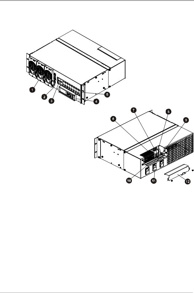
APS3-05X (Rack-Mounted Versions)
" Up to three Access Power Rectifiers, numbered 1 |
& |
|
to 3 from left to right (see page 1-6) |
3 |
|
# SM45 Supervisory Module (see page 1-7) |
||
4 |
||
$ One 2-pole Battery Circuit Breaker |
||
|
||
(APS3-059 only) |
5 |
|
% SM45 Display Module with keypad and LED |
||
' |
||
indicators (see Chapter 5) |
||
! Load Circuit Breakers – any combination of 6 A |
( |
|
or 25 A rated circuit breakers up to a maximum of |
|
|
eight, depending on customer requirements |
) |
|
|
16 DC Load Terminal Blocks (2 per DC Outlet)
Two Battery Terminal Blocks (APS3-059 only)
Two Battery Temperature Sensor Terminal
Blocks (APS3-059 only)
Battery Cable Clamp (APS3-059 only)
Cable Support Bracket
Three fused AC Power Sockets (one per rectifier) and labeled K1 to K3. K1 powers Rectifier 1, etc.
DC Output Cover (remove to access DC Output terminations)
Copyright © 2005-2006 Eaton Corporation. All Rights Reserved. |
1-3 |
|
IPN 997-00012-41D December 2006 |
||
|
General Description
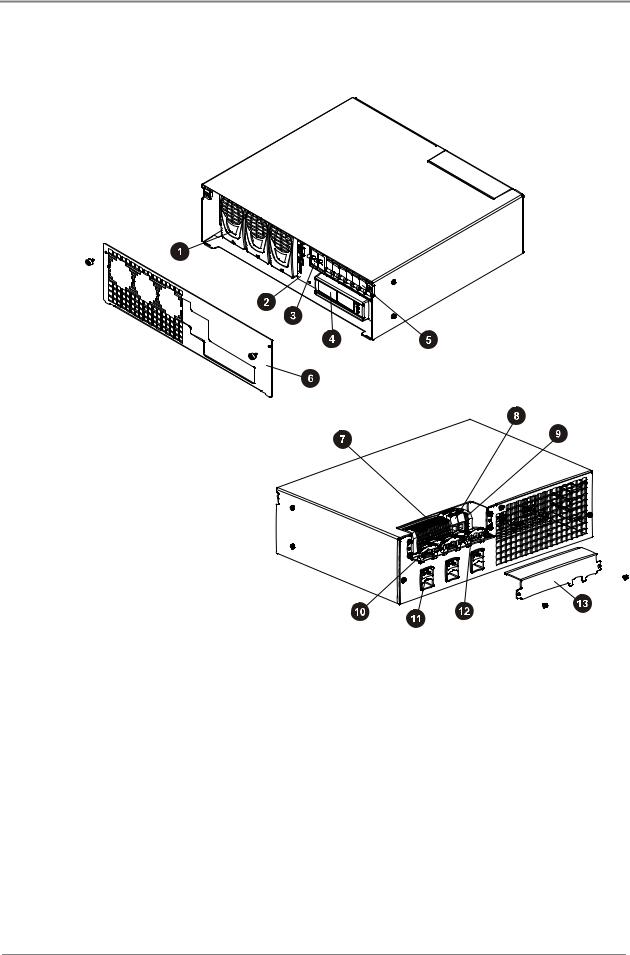
APS3-06X (Desktop Versions)
"Up to three Access Power Rectifiers, numbered 1 to 3 from left to right (see page 1-6)
#SM45 Supervisory Module (see page 1-7)
$One 2-pole Battery Circuit Breaker (APS3-061 only)
%SM45 Display Module with keypad and LED indicators (see Chapter 5)
!Load Circuit Breakers – any combination of 6 A or 25 A rated circuit breakers up to a maximum of eight, depending on customer requirements
&Front Cover
3
4
5
'
(
)
*
16 DC Load Terminal Blocks (2 per DC Outlet)
Two Battery Terminal Blocks (APS3-061 only)
Two Battery Temperature Sensor Terminal
Blocks (APS3-061 only)
Four Nylon Strain Relief Clamps
Three fused AC Power Sockets (one per rectifier) and labeled K1 to K3. K1 powers Rectifier 1, etc.
One Battery Cable Clamp (APS3-061 only)
DC Output Cover (remove to access DC output terminations)
1-4 |
Copyright © 2005-2006 Eaton Corporation. All Rights Reserved. |
|
IPN 997-00012-41D December 2006 |
||
|

Data Power Solutions Product Range
APS6-05X (Rack-Mounted Versions)
"
#
Three 2-pole Battery Circuit
Breakers (APS6-059 only)
Load Circuit Breakers – any combination of 6 A or 25 A rated circuit breakers up to a maximum of eight, depending on customer requirements
$Up to six Access Power Rectifiers, numbered 1 to 6 from left to right
(see page 1-6)
%SM45 Display Module with keypad and LED indicators
(see Chapter 5)
!
&
3
4
5
SM45 Supervisory Module
(see page 1-7)
16 DC Load Terminal Blocks (2 per DC Outlet)
Six Battery Terminal Blocks
(APS6-059 only)
Two Battery Temperature Sensor
Terminal Blocks (APS6-059 only)
Three Battery Cable Clamps
(APS6-059 only)
'Six fused AC Power Sockets (one per rectifier) and labeled K1 to K6. K1 powers Rectifier 1, etc.
(
)
DC Output Cover (remove to access DC output terminations)
Cable Support Bracket
Copyright © 2005-2006 Eaton Corporation. All Rights Reserved. |
1-5 |
|
IPN 997-00012-41D December 2006 |
||
|
General Description
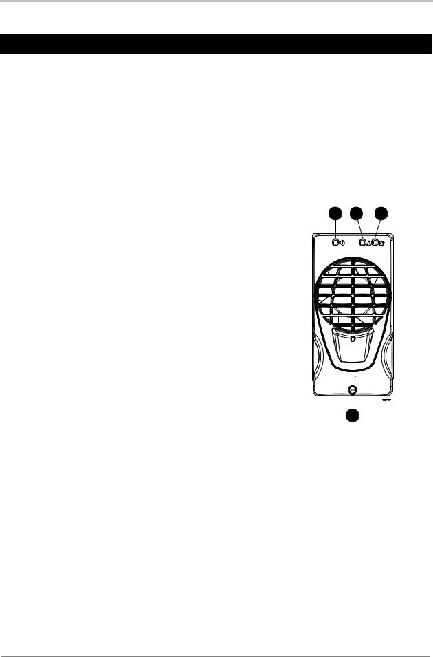
Access Power Rectifiers
Two types of fan-cooled, hot-pluggable Access Power Rectifiers are available.
•APU48 – 48 V, 720 W, (120 - 240 V AC)
•APR48 – 48 V, 1500 W, (208 - 240 V AC)
There are three status indicator LEDs on the Access Power Rectifier front panel (Power On, Urgent Alarm and Non-Urgent Alarm).
Details about replacing a rectifier can be found in Chapter 7.
"Power On LED (Green) – indicates that the rectifier is powered.
#Non-Urgent Alarm LED (Yellow) – indicates non-critical conditions, such as:
•Rectifier in power/current limit mode
(This normally happens for a short period of time when the batteries are recharging.)
•Rectifier operating in temperature turndown mode, because of high ambient temperature or low AC supply voltage
$Urgent Alarm LED (Red) – indicates critical fault conditions, that require urgent attention, such as:
•Rectifier failed
•Rectifier shut down
•AC supply failed (green LED off)
•Very high AC supply voltage
•DC overvoltage
%Retaining Screw (loosen to remove rectifier)
1 2 3
4
1-6 |
Copyright © 2005-2006 Eaton Corporation. All Rights Reserved. |
|
IPN 997-00012-41D December 2006 |
||
|
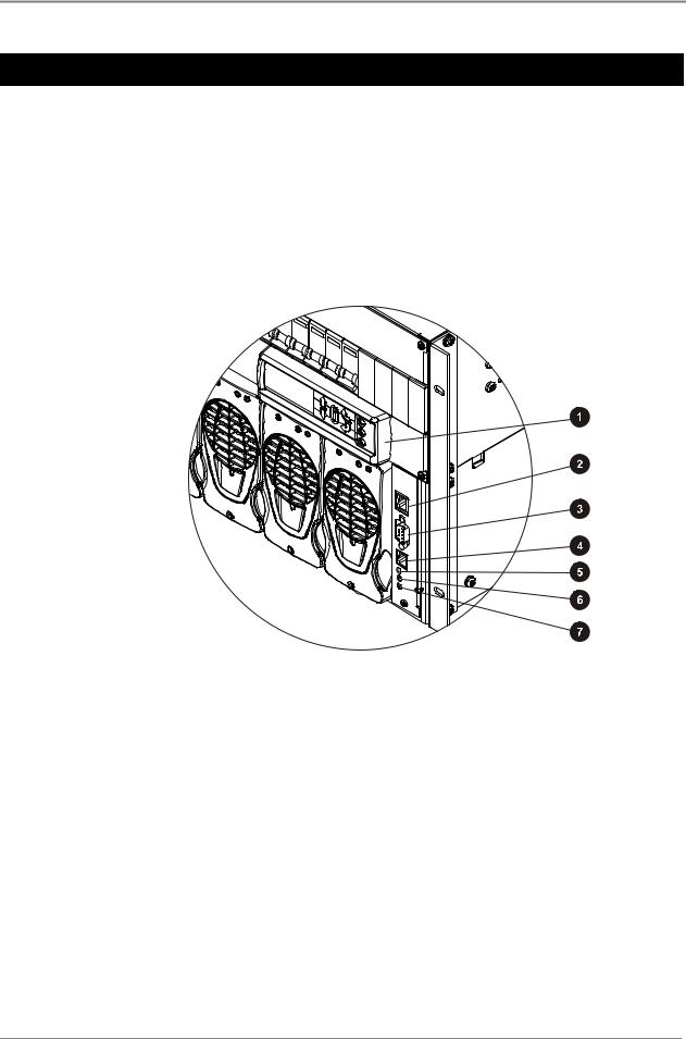
SM45 Supervisory Module
SM45 Supervisory Module
The SM45 supervisory module is an advanced control and monitoring solution for Data Power Solutions.
It provides a full suite of advanced communications options, including built-in Ethernet interface, Web server and SNMP agent. Details about the communications options can be found in Chapter 6.
Alarm notifications may be by SNMP traps.
The SM45 has an onboard audible indicator and two alarm LEDs. Details about the SM45 front panel can be found in Chapter 5.
"
#
$
%
Display Module with Keypad (see Chapter 5)
Ethernet Interface
RS-232 Serial Interface
Not used
!
&
3
Power On LED (green)
Non-urgent Alarm LED (yellow)
Urgent Alarm LED (red)
Copyright © 2005-2006 Eaton Corporation. All Rights Reserved. |
1-7 |
|
IPN 997-00012-41D December 2006 |
||
|

General Description
Low Voltage Disconnect (if applicable)
APS3-059, APS3-061 and APS6-059 models are equipped with a Low Voltage Disconnect (LVD) module.
The LVD disconnects the batteries at the LVD disconnect voltage to prevent damage to the batteries due to excessive deep discharge. After the batteries are disconnected, they recover to their open-circuit voltage. The LVD reconnects the batteries automatically after the AC supply is restored. After the batteries are reconnected, the power system recharges the batteries and powers the loads.
Both the LVD disconnect and reconnect voltages are configurable. The default LVD disconnect voltage is set to 44 V and the reconnect voltage to 48 V. This hysteresis band ensures that the open-circuit recovery of the discharged batteries does not rise above the LVD reconnect voltage.
1-8 |
Copyright © 2005-2006 Eaton Corporation. All Rights Reserved. |
|
IPN 997-00012-41D December 2006 |
||
|

Chapter 2
Pre-Installation
Overview
Topic |
Page |
Warnings |
2-2 |
|
|
Inspecting the Equipment and Reporting Damage |
2-6 |
|
|
Copyright © 2005-2006 Eaton Corporation. All Rights Reserved. |
2-1 |
|
IPN 997-00012-41D December 2006 |
||
|

Pre-Installation
Warnings
This section contains important warnings relating to:
•AC Inputs
•Equipment Classification
•Batteries (if applicable)
•DC Outputs
•Rectifiers
•Location and Environment
•Servicing
•EMC Compliance
AC Inputs
•Desktop Versions:
Pluggable Type A: Except for 120V input, if APS3-06X power systems are fitted with three rectifiers, then only two AC power cords may be connected to one building branch circuit. The third AC power cord must be connected to a separate building branch circuit. Failure to do so voids all safety approvals.
•The maximum earth leakage current of each Access Power Rectifier is 1.5 mA. Ensure that any upstream Residual Current Devices (RCDs) are appropriately rated.
•The AC power cords (supplying the power system) must be suitably rated for the environment and AC power distribution system. In addition, these AC power cords must be approved and installed to comply with local wiring regulations.
•The earth conductor of each AC power cord must have a minimum cross sectional area of 1 mm2 (0.00155 in2).
•The maximum length of each AC power cord should not exceed 3m (10 feet), unless local wiring regulations permit otherwise.
•Ensure that the AC supply is disconnected from those fused AC power sockets before checking or replacing their respective fuses.
•Each socket, K1 to K3 (APS3), and K1 to K6 (APS6), contain two fuses, FS1 and FS2.
CAUTION: DOUBLE-POLE / NEUTRAL FUSING
•Use only 15 A, 250 VAC, 6.3 x 32 mm, fast-acting fuses of the same type (Bussman ABC-15 or Littelfuse 314-015 Type 3AB) for continued protection against risk of fire.
Equipment Classification
•Data Power Solutions are classified as “Class 1” equipment that must be provided with an earth connected to the “Protective Earthing Conductor” in the building wiring. The earth conductor of each AC power cord must be connected to the “Protective Earthing Conductor” in the building wiring.
•APS3-06X (desktop versions) are classed as “Pluggable equipment Type A” and intended for use as “Desktop units”. All other units, APS3-05X and APS6-05X are “Pluggable Equipment Type B” or for “Permanently connection” in host equipment.
2-2 |
Copyright © 2005-2006 Eaton Corporation. All Rights Reserved. |
|
IPN 997-00012-41D December 2006 |
||
|

Warnings
Batteries (if applicable)
•Always install the batteries according to the relevant battery manufacturer’s instructions.
•Batteries are powerful sources of energy and present a potential electrical shock and energy hazard. The energy hazard is always present, even if the batteries are not connected. Avoid short circuiting terminals of opposite polarity.
•Batteries are heavy, awkward to handle and can cause personal injury. To prevent back injury, use correct lifting and bending techniques when moving batteries. If the batteries are too heavy to move, request assistance. Always comply with the relevant company rules or local regulations.
•Remove or cover rings, wristwatch and other metal jewelry that might be exposed to battery terminals, before installing batteries.
•Do not wear synthetic clothing when installing batteries.
•Always use insulated tools.
•Only use a clean soft damp cloth for cleaning the batteries. Do not use cleaning detergents or chemicals.
•When unpacking the batteries inspect them carefully for leaks, corrosion and possible damage. Report any damage or other battery related problems immediately to your battery supplier.
•Do not remove the factory-fitted transit insulation covers from the batteries until access to the battery terminals is required.
•Do not place tools, loose cables or metal objects (such as interconnecting bars) on top of batteries.
•Do not drop tools, loose cables or metal objects onto intercell connections or terminals of opposite polarity.
•Only terminate cables and interconnecting bars after confirming that the termination will not create a short circuit.
•Always tighten the battery terminal bolts according to the battery manufacturer’s specification. Failing to do so can cause erratic battery performance, possible damage to the battery, and/or personal injury.
•Always ensure that any shrouding supplied with the batteries is correctly fitted to cable connectors.
Copyright © 2005-2006 Eaton Corporation. All Rights Reserved. |
2-3 |
|
IPN 997-00012-41D December 2006 |
||
|

Pre-Installation
DC Outputs
•The DC outlets are floating to meet the isolation requirements for powering Power over Ethernet IEEE802.3af compatible devices.
In non-Power over Ethernet applications the positive or negative output of the DC outlets can be referenced to earth, if required.
•On APS3-06X (desktop versions), run the load cables through the supplied nylon strain relief clamps. Failure to fit the strain relief clamps and using the incorrect torque setting for tightening their captive screws voids all safety approvals.
Rectifiers
•To reduce the risk of electric shock and maintain optimum system cooling, always cover empty rectifier slots with blanking panels (Part Number: IPN 621-05722-63A).
•To avoid electrical shock, do not place hands inside the rectifier shelf.
•Rectifier cases may exceed 100ºC (212ºF), especially after prolonged operation. Use suitable gloves to remove the hot rectifier.
•Do not attempt to disassemble rectifiers. Return them, (in their original packaging) along with the completed Equipment Incident Report, to your local Powerware DC product representative for replacement or repair.
Location and Environment
•Data Power Solutions (rack-mounted and desktop versions) meet the safety and fire enclosure requirements (as specified in AS/NZS 60950.1, EN 60950-1, IEC 60950-1 and UL 60950-1). Always mount APS3-05X and APS6-05X powers systems in 19-inch wide host equipment racks (enclosed or open type) securely bolted to the floor and position the desktop versions (APS3-06X) on a surface that supports the weight (12kg / 26lb) of the power system.
•To maintain optimum system cooling, keep the front and rear of the power system clear from walls or other equipment. The minimum recommended clearance distance at the front and rear of the power system is 50 mm (2”). No top and bottom clearance is required.
•The location must provide adequate airflow around the unit, in an atmosphere free from excessive dust, corrosive fumes or conductive contaminants.
•Dust build-up within the DC power system may cause premature failure. In dusty environments filter the ventilation air entering the equipment room. Ensure regular cleaning of the air filters.
•Do not allow water or any foreign object to enter the power system. Do not place objects containing liquid on top of or near the unit.
•Flooded cell and VRLA lead acid batteries can emit explosive gases and must be installed with adequate ventilation. Refer to the battery manufacturer or supplier for advice on minimum ventilation levels, or refer to Application Note AN0080 available from Eaton.
2-4 |
Copyright © 2005-2006 Eaton Corporation. All Rights Reserved. |
|
IPN 997-00012-41D December 2006 |
||
|

Warnings
Servicing
•Data Power Solutions contain hazardous voltages. Do not attempt to disassemble or service the unit if you are not qualified. Only service personnel of Eaton Corporation’s Telecommunications Solutions Division or their authorized service agents are permitted to service the unit.
•If the power system requires servicing other than external battery or rectifier replacement, isolate the unit first, as follows:
1 Unplug the AC supply cords from the AC power outlets.
2 Disconnect the external batteries, by switching off the battery circuit breakers.
EMC Compliance
•Data Power Solutions may be used in close proximity to other electronic equipment provided installation is carried out according to instructions in this manual. However, proper installation and compliance with EMC standards does not guarantee that the power system will not respond to electromagnetic disturbances, or will not cause interference to other equipment in a particular installation.
•Data Power Solutions comply with part 15 of the FCC (Federal Communications Commission) rules. Operation is subject to the following two conditions:
1 This device may not cause harmful interference, and
2 This device must accept any interference received, including interference that may cause undesired operation.
•Changes or modifications to Data Power Solutions not approved by Eaton Corporation could void FCC authority to operate that equipment.
•Data Power Solutions have been tested and found to comply with the limits for a Class B digital device, pursuant to part 15 of the FCC Rules. These limits are designed to provide reasonable protection against harmful interference in a residential installation. This equipment generates, uses, and can radiate radio frequency energy and, if not installed and used in accordance with the instructions, may cause harmful interference to radio communications. However, there is no guarantee that the interference will not occur in a particular installation. If this equipment does cause harmful interference to radio or television reception, which can be determined by turning the equipment off and on, the user is encouraged to try to correct the interference by one or more of the following measures:
Reorient or relocate the receiving antenna.
Increase the separation between the equipment and receiver.
Connect the equipment into an outlet on a circuit different from that to which the receiver is connected.
Consult the dealer or an experienced radio/TV technician for help.
Copyright © 2005-2006 Eaton Corporation. All Rights Reserved. |
2-5 |
|
IPN 997-00012-41D December 2006 |
||
|

Pre-Installation
Inspecting the Equipment and Reporting Damage
Unpack the power system and inspect it carefully for possible damage that may have occurred while in transit.
Next, check the equipment against the packing list (supplied with the equipment) and ensure that you have received the correct type of Access Power Rectifiers (either APR48 or APU48).
Report any damage or incorrect shipment immediately, using a copy of the Equipment Incident Report (at the back of this guide) to supply all relevant details. Fax the completed form to your local Powerware DC product representative.
Keep the original packaging. You will need it if any equipment needs to be returned to your local Powerware DC product representative.
2-6 |
Copyright © 2005-2006 Eaton Corporation. All Rights Reserved. |
|
IPN 997-00012-41D December 2006 |
||
|
Chapter 3
Installation
Overview
Topic |
Page |
Mounting the Power System |
3-2 |
|
|
DC Installation Practices |
3-3 |
|
|
Connecting the DC Load Cables |
3-3 |
|
|
Installing the External Batteries (if applicable) |
3-7 |
|
|
Connecting the Battery Cables (if applicable) |
3-8 |
|
|
Installing the Battery Temperature Sensor (if batteries are fitted) |
3-10 |
|
|
Connecting the Power System to the AC Supply |
3-12 |
|
|
Copyright © 2005-2006 Eaton Corporation. All Rights Reserved. |
3-1 |
|
IPN 997-00012-41D December 2006 |
||
|
Installation
Mounting the Power System
Location and Environment
Data Power Solutions (rack-mounted and desktop versions) meet the safety and fire enclosure requirements (as specified in AS/NZS 60950.1, EN 60950-1, IEC 60950-1 and UL 60950-1).
•Rack-Mounted Versions: APS3-05X and APS6-05X series power systems may be mounted in 19-inch wide host equipment racks (enclosed or open type) securely bolted to the floor.
•Desktop Versions: APS3-06X series power systems may be positioned on any surface that supports the weight of the power system.
The location must provide adequate airflow around the unit, (as per Clearance Requirements below) in an atmosphere free from excessive dust, corrosive fumes, or conductive contaminants.
Dust build-up within the DC power system may cause premature failure. In dusty environments filter the ventilation air entering the equipment room. Ensure regular cleaning of the air filters.
VRLA lead acid batteries can emit explosive gases and must be installed with adequate ventilation. Refer to the battery manufacturer or supplier for advice on minimum ventilation levels, or refer to Application Note AN0080 available from Eaton.
Clearance Requirements
All Data Power Solutions (rack-mounted and desktop versions) require the following minimum clearances:
•Front and Rear Clearance – 50 mm (2”) from walls and other equipment, required for optimum system cooling and access.
•Top and Bottom Clearance – None
Rack Installation (rack-mounted versions only)
" APS3-05X and APS6-05X power systems come pre-assembled with two 19-inch rack-mounting brackets.
# The two rack-mounting brackets can be moved backwards and lined up with alternative bracket-mounting holes, to provide greater mounting flexibility. Ensure the same screws are used.
2
1
3-2 |
Copyright © 2005-2006 Eaton Corporation. All Rights Reserved. |
|
IPN 997-00012-41D December 2006 |
||
|

DC Installation Practices
Important Notes for Rack Mounted Systems:
•If this DC power system is installed in a closed or multi-unit rack assembly ensure that the ambient temperature is less than 40°C.
•Ensure that the air flow is not restricted.
•Ensure that the system’s weight is adequately and evenly supported.
•Take note of the maximum AC current stated on the nameplate. Ensure that the AC supply is correctly rated.
•Ensure that reliable earthing is maintained. Carefully check earth continuity from the branch circuit to the DC power system.
DC Installation Practices
Before you start connecting the DC load and battery cables (if applicable) to a power system, please read the following DC Installation Practices:
•On APS3-06X (desktop versions), run the DC load cables through the supplied nylon strain relief clamps at the rear. (See page 3-5 for details.) Failure to fit the strain relief clamps and using the incorrect torque setting for tightening their captive screws voids all safety approvals.
•To easily distinguish between positive and negative load cables, we recommend using cables with different colors (as specified by local wiring regulations). The same applies to battery cables (if applicable).
•To reduce inductive coupling, separate DC load, battery and communications cabling from AC supply cables. If the cables have to cross, run them at right angles to the AC supply cables.
•In order to minimize parasitic cable inductance and reduce electromagnetic interference (EMI), all DC load cables should be routed in close proximity to one another, and large current loops should be avoided. The same applies to battery cables (if applicable).
Connecting the DC Load Cables
Eight DC outlets (labeled 1 to 8) are available for connecting your equipment power cables. Each DC outlet is protected by a corresponding 6 A or 25 A circuit breaker (accessible from the DC distribution at the front). The current rating of the corresponding circuit breaker determines the current rating of a DC outlet.
The DC outlets are floating to meet the isolation requirements for powering
Power over Ethernet IEEE802.3af compatible devices. In non-Power over Ethernet applications the positive or negative output of the DC outlets can be referenced to earth, if required.
Copyright © 2005-2006 Eaton Corporation. All Rights Reserved. |
3-3 |
|
IPN 997-00012-41D December 2006 |
||
|
Installation
DC Load Cable Specifications
No DC load cables are supplied.
DC load cables are sized differently, depending on whether you connect to 6A or 25A DC outlets. All DC load cables must meet the following specifications and no other cable sizes must be used.
6 A DC Outlets: UL 1015*, 18 AWG (1mm2), multi-strand cable
25 A DC Outlets: UL 1015*, 12 AWG (4mm2), multi-strand cable
Cable Length: |
3m (10 feet) maximum |
*Required to maintain approval compliance.
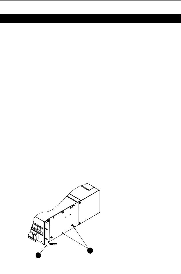
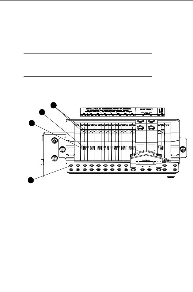
APS3-05X and APS6-05X (Rack-Mounted Versions)
3
2
1
4
"Terminate the negative load cable(s) at the (-) terminal block(s) of the DC outlet(s).
#Terminate the positive load cable(s) at the (+) terminal block(s) of the DC outlet(s).
Ensure that the polarity at the DC outlet(s) matches the power input polarity of your equipment. Connecting reverse polarity equipment power cables to the DC outlets of a power system might cause damage to your equipment. Such damage is not covered by our warranty.
Ensure that the correct cable sizes have bee used (18 AWG for 6 A outlets and 12 AWG for 25 A outlets).
$To ensure reliable connections at the terminal blocks of the DC outlets, torque the clamp-screws 0.4 – 0.6 Nm (3.5 – 5.3 lb-in).
%Use cable-ties (not supplied) and the provided cable-tie holes on the cable support bracket to tie down the load cables.
3-4 |
Copyright © 2005-2006 Eaton Corporation. All Rights Reserved. |
|
IPN 997-00012-41D December 2006 |
||
|
Loading...