


POWERWARE® 9120
User’s Guide
700 VA - 3000VA
www.powerware.com

POWERWARE® 9120
700, 1000, 1500, 2000 & 3000VA
User’s Guide
Important Notice
The UPS ground (earth) conductor carries leakage current from the loads in addition to any leakage current generated by the UPS. This UPS generates no more than 1 mA of current. To limit the total leakage current to 3.5 mA, the load leakage must be limited to 2.5 mA. The three-wire receptacle that you plug the UPS into must have a good (lowimpedance) ground (protective earth) connection to provide a safe path for leakage current.
OMM91203kRev1.qxd
© Copyright 2007, Eaton Powerware. All rights reserved.

If You Have a Question
Customer Support
If you have a question or problem, Table 10, Troubleshooting, may help. If you need more help, please have your UPS model number and serial number (on the back label) nearby, and call the Eaton Powerware office nearest you (see the offices section). Eaton Powerwares’ service technicians have in-depth knowledge of the UPS and power problems.
Eaton Powerware may tell you the UPS must be returned. If this happens, we will give you a Return Authorisation (RA) number. When you return a Powerware 9120 to the factory for any reason, please use the original packing material in which your unit was shipped to you. You may be responsible for repair charges for damaged units which are not packed in Powerware packing material. If you have discarded the original packing material, please call the nearest Eaton Powerware office so that we can ship new packing material to you. If you have any questions, please feel free to call or fax the nearest Eaton powerware office. Please do not return your Powerware 9120 without calling Eaton powerware first. Eaton Powerware will advise you where to ship your Powerware 9120.
Eaton Powerware reserves the right to change specifications without prior notice.

1
Table of Contents
|
Safety Instructions . . . . . . . . . . . . . . . . . . . . . . . . . . . . . . . . . |
.2 |
|
1.0 |
UPS Features . . . . . . . . . . . . . . . . . . . . . . . . . . . . . . . . . . . . |
.3 |
|
2.0 |
Quick Startup . . . . . . . . . . . . . . . . . . . . . . . . . . . . . . . . . . . . . |
.6 |
|
3.0 |
Operation . . . . . . . . . . . . . . . . . . . . . . . . . . . . . . . . . . . . . . . . |
.7 |
|
3.1 |
UPS Front Panel . . . . . . . . . . . . . . . . . . . . . . . . . . . . . . . . . . |
.7 |
|
|
3.2 Turning the UPS On . . . . . . . . . . . . . . . . . . . . . . . . . . . . . |
.8 |
|
|
3.3 Turning the UPS Off . . . . . . . . . . . . . . . . . . . . . . . . . . . . . |
.8 |
|
|
3.4 |
Standby Mode . . . . . . . . . . . . . . . . . . . . . . . . . . . . . . . . . |
.8 |
|
3.5 |
Diagnostic Tests . . . . . . . . . . . . . . . . . . . . . . . . . . . . . . . . |
.8 |
4.0 |
Configuration . . . . . . . . . . . . . . . . . . . . . . . . . . . . . . . . . . . . . |
.9 |
|
5.0 |
Additional UPS Features . . . . . . . . . . . . . . . . . . . . . . . . . . . . |
12 |
|
|
5.1 |
Inverter Shutdown . . . . . . . . . . . . . . . . . . . . . . . . . . . . . . |
12 |
|
5.2 |
Network Transient Protector . . . . . . . . . . . . . . . . . . . . . . . |
12 |
|
5.3 |
Load Segments . . . . . . . . . . . . . . . . . . . . . . . . . . . . . . . . |
12 |
|
5.4 |
Communication Port . . . . . . . . . . . . . . . . . . . . . . . . . . . . . |
13 |
|
5.5 |
Comunication Slot . . . . . . . . . . . . . . . . . . . . . . . . . . . . . . |
13 |
|
5.6 |
SNMP/Web Adaptor . . . . . . . . . . . . . . . . . . . . . . . . . . . . . |
13 |
|
5.7 |
Relay Card . . . . . . . . . . . . . . . . . . . . . . . . . . . . . . . . . . . . |
14 |
6.0 |
Installing Lansafe Software . . . . . . . . . . . . . . . . . . . . . . . . . . |
14 |
|
7.0 |
Replacing the Batteries . . . . . . . . . . . . . . . . . . . . . . . . . . . . . |
15 |
|
|
7.1 |
How to Replace Internal Batteries . . . . . . . . . . . . . . . . . . |
16 |
|
7.2 |
Recyling the Used Battery . . . . . . . . . . . . . . . . . . . . . . . . |
16 |
8.0 |
Specifications . . . . . . . . . . . . . . . . . . . . . . . . . . . . . . . . . . . . . |
17 |
|
9.0 |
Troubleshooting . . . . . . . . . . . . . . . . . . . . . . . . . . . . . . . . . . . |
20 |
|
10.0 |
Warranty . . . . . . . . . . . . . . . . . . . . . . . . . . . . . . . . . . . . . . . . |
24 |
|
|
Eaton Powerware Australia/New Zealand Offices . . . . . . . . . . |
28 |
|
Trademarks
Windows is a registered trademark of Microsoft Corporation.
All other brand and product names are trademarks or registered trademarks of their respective holders.

2
Safety Instructions
IMPORTANT SAFETY INSTRUCTIONS! SAVE THESE INSTRUCTIONS!
This User Guide contains important instructions for your Powerware 9120 that must be followed during installation and maintenance of the UPS and batteries.
 CAUTION!
Whenever the Powerware 9120 is “On,” there may be dangerous voltage present at the unit’s outlets. This is true because the unit’s battery supplies power even if the unit is not plugged into the wall outlet. The unit contains dangerous voltages.
To reduce the risk of electric shock, install in a temperature-controlled and humiditycontrolled indoor area free of conductive contaminants.
The power supply cord is intended to serve as the disconnect device. The socket-outlet shall be near the equipment and shall be easily accessible.
With the exception of the user-replaceable batteries, all servicing of this equipment must be performed by qualified service personnel.
Before maintenance or repair, all connections must be removed. Before maintenance, repair, or shipment, the unit must be completely switched off and unplugged or disconnected.
The installation and use of this product must comply with all national, federal, state, municipal, or local codes that apply. For assistance, call Eaton Powerware Service or your local Eaton Powerware office.
If the Powerware unit has been damaged during shipment, call your vendor immediately.
If the Powerware unit is stored, the batteries should be recharged every 6 months. If stored
above 25° Celsius, recharge the batteries more often.
3
1.0UPS Features
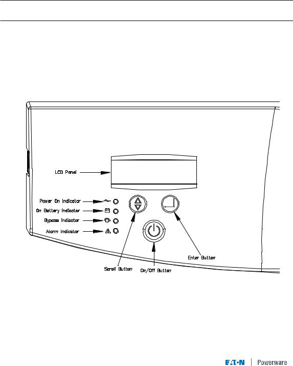
The Powerware 9120 provides protection against power problems, including power outages, brownouts, and sudden increases in power. It also provides spike suppression and line noise filtering to protect your equipment. Front panel LEDs and an audible alarm keep you aware of the unit’s status. Use the drawings on this and the following pages to identify features of the unit.
Fig 1. Powerware 9120 Controls and Indicators

4
USB Port |
Communication Slot |
Communication Port 
Fan
Inverter Shutdown
Connector
Load Segment 1
2 x Australian 10A 
Input Connector 
IEC C14 10A
M O DEL NO .:06250700A |
|
|
P/N:06250700A |
|
|
INPUT |
:208/220/230V/240V, |
|
|
50/60Hz,3.4/3.2/3.0/2.9A |
|
INPUT |
:24V,25A |
|
O UTPUT |
:208/220/230/240V,50/60Hz |
|
|
700VA/490W |
|
USE W ITH:2BAT 700 |
|
|
ASSEM BLED IN TAIW AN |
612-09910-00 |
|


 Network Surge Suppression

 Battery Connector
Load Segment 2


 2 x Australian 10A
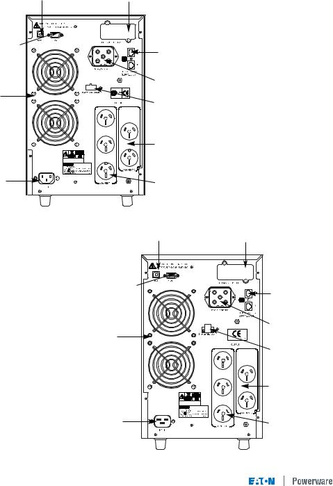
Fig 2. 700VA and 1000VA Rear Panel
USB Port |
Communication Slot |
|
Communication Port |
|
|
Inverter Shutdown |
Battery Connector |
|
|
||
Connector |
|
|
Fan |
Network Surge |
|
Suppression |
||
|
||
|
Load Segment 1 |
|
|
2 x Australian 10A |
|
P/O Load Segment 2 |
|
|
Australian 10A |
|
|
Input Connector |
P/O Load Segment 2 |
|
Australian 10A |
||
IEC C14 10A |
||
|
Fig 3. 1500VA Rear Panel
5
USB Port |
Communication Slot |
Communication Port |
Network Surge |
|
|
||
|
Suppression |
|
|
Battery Connector |
|
Fan |
Inverter Shutdown |
|
|
Connector |
|
|
Load Segment 2 |
|
|
2 x Australian 10A |
|
Input Connector |
Load Segment 1 |
|
IEC C14 10A |
||
3 x Australian 10A |
||
|
Fig 4. 2000VA Rear Panel
USB Port |
Communication Slot |
Communication Port |
Network Surge |
|
|
||
|
Suppression |
|
|
Battery Connector |
|
Fan |
Inverter Shutdown |
|
|
||
|
Connector |
|
|
Load Segment 2 |
|
|
2 x Australian 15A |
|
Input Connector |
Load Segment 1 |
|
3 x Australian 15A |
||
IEC C20 16A |
||
|
Fig 5. 3000VA Rear Panel
6
2.0Quick Startup
1Your Powerware 9120 UPS has a removable power cord. Connect the power cord to the back of the unit and plug the UPS into a wall outlet. The LCD backlight will illuminate and the fan will run, but no output power is available.
2Let the unit charge the battery for at least 3 hours. You may use the unit while the battery charges, but the battery backup runtime will be reduced until the battery is fully charged.
3Start the Powerware 9120 by pressing and holding the On/Standby button (large button in the center of the front panel) in for about one second. Note: To turn the unit on, the On/Standby button must be pressed for about one second and for about 5 seconds to turn the unit off.
3.a. When it starts, the unit beeps once, then twice, and lights the “Power On” LED. The unit indicates “On Delay” on the LCD and performs an internal system and battery test. Next, the Powerware 9120 applies AC output to the back panel receptacles and indicates “On Line” on the LCD.
3.b. After 10 seconds or less, the self test is complete. The green LED will come on and remain on. If the unit beeps, or if the green LED does not remain on even though input power is available from the wall outlet, go to the Troubleshooting section.
4Switch off the equipment you want to protect, and plug each load into the outlets on the back of the Powerware 9120. Refer to Section 5.3 for detail on the load segment feature.
5Switch on the protected equipment, one load at a time. If the UPS beeps an alarm when you start your equipment, the UPS may be overloaded. See the Troubleshooting section.
The LCD on the front of the UPS shows the % of load capacity that your equipment is using. See Section 3.0 Operation for more information on checking the load %..
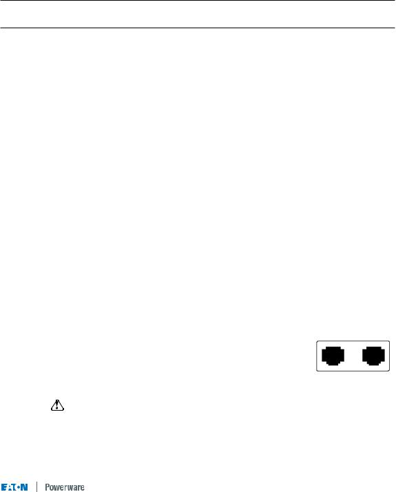
6 The RJ-45 Surge Protection jacks will protect equipment that uses an RJ-11 or RJ-45 connection. Plug the 10BASE-T network connection into the surge protection jack labeled “IN” on the back of the Powerware 9120. Plug the protected equipment into the surge protection jack labeled “OUT.” Network cabling is not provided. This connection is optional. It is not needed to use the Powerware 9120.
Do not use this connection for modems or telephones
Out In
NETWORK SURGE SUPPRESSION
RJ-45 Jacks
7 Please fill out the warranty registration card in Section 10 and return it to your local Eaton Powerware office.
7
3.0 |
Operation |
|
|
This section describes: |
|
|
|
• |
The UPS front panel |
• |
Standby mode |
• |
Turning the UPS on and off |
• |
Diagnostic tests |
• Starting the UPS on battery
3.1UPS Front Panel
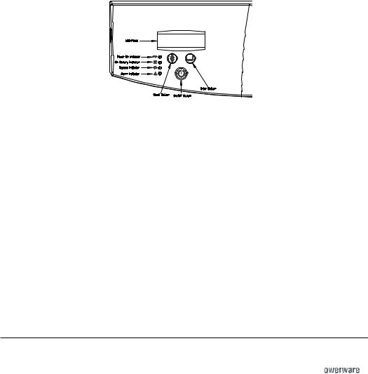
The UPS front panel indicates the UPS status and also identifies potential power problems. Figure 6 shows the UPS front panel indicators and controls.
Figure 6. UPS Front Panel
NOTE If the alarm beeps or if the  indicator is on, see Table 10 in Section 9.0 to identify and correct the problem. To configure parameters through the front panel, see Section 4.0 "Configuration".
Display Mode
To view the UPS current settings, press the button for one second and release. Use the button to scroll through the list of settings, which appear in the following order:
LCD Message |
Description |
I/P VOLT= xxx.xV |
Input voltage. |
I/P FREQ= xx.xHZ |
Input frequency. |
O/P VOLT= xxx.xV |
Output voltage. |
O/P FREQ= xx.xHZ |
Output frequency. |
O/P Load = x% |
Approximate percentage of UPS load capacity being used |
|
by the protected equipment. |
O/P Watt= xW |
Output watts. |
O/P VA= xVA |
Output VA. |
O/P Cur= x.xA |
Output current. |
BAT VOLT= xx.xV |
Battery voltage. |
BAT CHARGE= xxx% |
Approximate percentage of battery capacity remaining. |
BackUp Time= xxxM |
Approximate battery time remaining in minutes. The display |
|
changes to seconds after one minute (Backup Time= xxxS). |
CPU Version x.xx |
Firmware revision level. |
NOTE The UPS exits Display mode automatically after five seconds if the button is not pressed. To lock the meter screen, press the button until a beep is heard (3 seconds) then release it. To unlock the display, press the button until a beep is heard, then release it. 


 Loading...