


 Loading...
Instruction Manual for the
Eaton RTC-50 Automatic
Transfer Switch Controller
Instructional Booklet
New Information
Description |
Page |
1. Introduction . . . . . . . . . . . . . . . . . . . . . . . . . . . . . . . 2
2. Hardware Description . . . . . . . . . . . . . . . . . . . . . . . . 4
3. Operation . . . . . . . . . . . . . . . . . . . . . . . . . . . . . . . . . 6
4. Programming . . . . . . . . . . . . . . . . . . . . . . . . . . . . . . 7
5. Troubleshooting and Maintenance . . . . . . . . . . . . . . . . 8
Appendix A: Operational Flowchart . . . . . . . . . . . . . . . 9
IB00405004E-70-8664 |
For more information visit: www.eaton.com |

Instructional Booklet
Page 2 |
Effective: June 2007 |
Instruction Manual for the Eaton RTC-50 Automatic Transfer Switch Controller
SECTION 1: INTRODUCTION
 CAUTION
ALL POSSIBLE CONTINGENCIES THAT MAY ARISE DURING INSTALLATION, OPERATION, OR MAINTENANCE, AND ALL DETAILS AND VARIATIONS OF THIS EQUIPMENT DO NO PURPORT TO BE COVERED BY THESE INSTRUCTIONS. IF FURTHER INFORMATION IS DESIRED BY THE PURCHASER REGARDING A PARTICULAR INSTALLATION, OPERATION, OR MAINTENANCE OF PARTICULAR EQUIPMENT, PLEASE CONTACT AN AUTHORIZED EATON ELECTRICAL SALES REPRESENTATIVE OR THE INSTALLING CONTRACTOR.
1.1 Preliminary Comments and Safety Precautions
This technical document is intended to cover all aspects associated with the installation, application, operation, and maintenance of the Automatic Transfer Switch Controller (RTC-50). It is provided as a guide for authorized and qualified personnel only in the selection and application of the RTC-50 controller. Please refer to the specific WARNING and CAUTION in Section 1.1.2 before proceeding. If further information is required by the purchaser regarding a particular installation, application, or maintenance activity, please contact an authorized Eaton Electrical Sales Representative or the installing contractor.
1.1.1 Warranty and Liability Information
No warranties, expressed or implied, including warranties of fitness for a particular purpose of merchantability, or warranties arising from course of dealing or usage of trade, are made regarding the information, recommendations and descriptions contained herein. In no event will Eaton be responsible to the purchaser or user in contract, in tort (including negligence), strict liability or otherwise for any special, indirect, incidental or consequential damage or loss whatsoever, including but not limited to damage or loss of use of equipment, plant or power system, cost of capital, loss of power, additional expenses in the use of existing power facilities, or claims against the purchaser or user by its customers resulting from the use of the information and descriptions contained herein.
1.1.2 Safety Precautions
All safety codes, safety standards, and/or regulations must be strictly observed in the installation, operation, and maintenance of this device.
 WARNING
COMPLETELY READ AND UNDERSTAND THE MATERIAL PRESENTED IN THIS DOCUMENT BEFORE ATTEMPTING INSTALLATION, OPERATION, OR APPLICATION OF THE EQUIPMENT. IN ADDITION, ONLY QUALIFIED PERSONS SHOULD BE PERMITTED TO PERFORM ANY WORK ASSOCIATED WITH THIS EQUIPMENT. ANY WIRING INSTRUCTIONS PRESENTED IN THIS DOCUMENT MUST BE FOLLOWED PRECISELY. FAILURE TO DO SO COULD CAUSE PERMANENT EQUIPMENT DAMAGE.
1.2 General Information
Automatic Transfer Switches (ATS) are used to protect critical electrical loads against loss of power. The load’s Utility power source is backed up by an alternate power source such as a Generator. An ATS is connected to both the Utility and Generator power sources and supplies the load with power from one of the two sources. In the event that power is lost from Utility, the ATS transfers the load to the Generator power source. Once Utility power is restored, the load is automatically transferred back to the Utility power source.
An intelligence system initiates the transfer when the Utility power fails or falls below a preset voltage. An engine start is then initiated by the Generator and the ATS transfers to the Generator power source when sufficient Generator voltage is available. When the Utility power is restored, the ATS automatically transfers back to the Utility and the Generator will shut down after a time delay.
ATSs automatically perform the transfer function, and include three basic elements:
1.Main contacts to connect and disconnect the load to and from the power sources.
2.Solenoids to make the transfer of the main contacts from source to source.
3.Intelligence/supervisory circuits to constantly monitor the condition of the power sources and thus provide the intelligence necessary for the switch and related circuit operation.
This manual deals with the third basic element of the ATS, the required intelligence/supervisory circuits. The RTC-50 controller advances the application of intelligence, supervisory, and programming capabilities for ATS equipment.
 WARNING
THE WARNINGS AND CAUTIONS INCLUDED AS PART OF THE PROCEDURAL STEPS IN THIS DOCUMENT ARE FOR PERSONNEL SAFETY AND PROTECTION OF EQUIPMENT FROM DAMAGE. AN EXAMPLE OF A TYPICAL WARNING LABEL HEADING IS SHOWN ABOVE TO FAMILIARIZE PERSONNEL WITH THE STYLE OF PRESENTATION. THIS WILL HELP TO INSURE THAT PERSONNEL ARE ALERT TO WARNINGS, WHICH APPEAR THROUGHOUT THE DOCUMENT. IN ADDITION, WARNINGS AND CAUTIONS ARE ALL UPPER CASE AND BOLDFACE.
1.3 Product Overview
The RTC-50 controller is a comprehensive, multi-function, micro- processor-based ATS controller. Designed to meet the needs of markets worldwide, the RTC-50 controller:
•Is a UL Listed Component
•Complies with UL 1008/ CSA 22.2-178
•Complies with UL 991 environmental tests
•Complies with IEC 61000-4-2, 61000-4-3, 61000-4-4, 61000- 4-5, 61000-4-6, and 61000-4-11
•Complies with CISPR 11, Class B
•Complies with FCC Part 15, Class B
•Meets European Standards Conformance (CE mark)
The RTC-50 controller provides an unmatched degree of programmed flexibility to address the needs of any system. It operates on 240 VAC, single-phase at 50 or 60 Hz. The RTC-50 controller monitors the condition of the line voltage of both the Utility and Generator power sources. The RTC-50 controller provides the necessary intelligence to insure that the transfer switch operates properly through a series of programmed sensing and timing functions.
For more information visit: www.eaton.com |
IB00405004E-70-8664 |

Instructional Booklet
Instruction Manual for the Eaton RTC-50 Automatic Transfer Switch Controller
Effective: June 2007 |
Page 3 |
A standard RTC-50 controller will:
•Monitor Utility and Generator power source voltages
•Provide undervoltage protection of the Utility and Generator power sources
•Permit easy customer set-up
•Provide source status indications
•Provide remote indication that generator maintenance needs to be performed
1.4 Glossary
With respect to their use within this document and as they relate to transfer switch and controller operation, the following terminology is defined.
Available
A source is defined as “available” when it is within its undervoltage setpoint range.
Connected
Connected is defined as when the input is shorted by an external contact or connection.
Failed or Fails
A source is defined as “failed” when it is outside of the applicable voltage ranges for the nominal voltage and for a time exceeding 0.5 seconds after the time delay emergency fail (TDEF) time delays expires.
Failsafe
Failsafe is a feature that prevents disconnection from the only available power source and also forces a transfer or re-transfer operation to the only available power source.
Re-Transfer
Re-transfer is defined as a change of the load connection from the Generator to the Utility.
Utility
Utility is the primary source (normal source, normal power source, or normal).
Generator
Generator is the secondary source (emergency source, emergency power source, emergency, standby, or backup source).
Utility: Failed or Fails
Utility is defined as “failed” when it is outside of its undervoltage setpoint range.
Generator: Failed or Fails
Generator is defined as “failed” when it is outside of its undervoltage setpoint range for a time exceeding 0.5 seconds after the TDEF time delay expires.
Transfer
Transfer is defined as a change of the load connection from the Utility to the Generator power source.
Unconnected
Unconnected is defined as when the input is not shorted by an external contact or connection.
1.5 Functions/Features
The primary function of RTC-50 controller is to accurately monitor the Utility and Generator power sources and provide the necessary intelligence to operate the ATS in an appropriate and timely manner. In addition, the RTC-50 controller provides status information through on-board and remote indicators.
The following is a list of the features of the RTC-50 controller.
1.Time Delay Normal to Emergency (TDNE)
This feature provides a time delay when transferring from the Utility to the Generator power source. Timing begins when the Generator becomes available. It permits controlled transfer of the load circuit to the Generator.
Jumper selectable at 20 or 50 seconds. Default is 20 seconds.
3.Time Delay Emergency to Normal (TDEN)
This feature provides a time delay of the re-transfer operation to permit stabilization of the Utility source. Timing begins when the Utility becomes available. If the Generator fails during timing, then re-transfer is delayed for up to 6 seconds to allow the Generator to recover.
Fixed setting of 10 seconds
5.Generator Monitoring and Protection
This feature provides monitoring and protection based on the Generator voltage setpoints. All feature 5 functions are failsafe operations.
5J. All Phase Undervoltage Protection
Dropout: 168 Vac (70% of 240 Vac nominal) Pickup: 192 Vac (80% of 240 Vac nominal)
7.Time Delay Emergency Fail (TDEF)
This feature provides a time delay that prevents a connected Generator source from being declared “failed” in order to override momentary generator fluctuations. If the Generator remains in the failed state then, after the TDEF timer expires, the transfer switch will proceed with the programmed sequence for re-transfer.
Fixed setting of 6 Seconds
12.Power Source Annunciation
This feature provides LEDs to indicate power source availability.
12G. Utility - Available
This feature provides a green LED that, when lit, indicates that the Utility is available.
12H. Generator - Available
This feature provides a red LED that, when lit, indicates that the Generator is available.
15M. Load Shed
Two sets of contacts are available and can be used to control large connected loads on the Generator (i.e. air conditioners, hot tubs, etc.). The contacts are rated for 250 Vac, 5 amps.
IB00405004E-70-8664 |
For more information visit: www.eaton.com |
Instructional Booklet
Page 4 |
Effective: June 2007 |
Instruction Manual for the Eaton RTC-50 Automatic Transfer Switch Controller
26.Utility - Monitoring and Protection
This feature provides Utility monitoring and protection functions. If the Utility power source fails, then the RTC50 will begin the sequence of operations necessary to transfer the load circuit to the Generator power source. All Feature 26 monitoring and protection functions are failsafe operations.
26D. Go To Generator
This feature provides the capability for an external contact closure to initiate a transfer from Utility to Generator. After the Generator becomes available, TDNE will time out before the transfer to Generator takes place. Re-transfer will occur when the external contact is opened or under a failsafe condition. A connection point for the connection of an external contact is provided.
26P. All Phase Undervoltage Protection
Dropout: 168 Vac (70% of 240 Vac nominal) Pickup: 192 Vac (80% of 240 Vac nominal)
SECTION 2:HARDWARE DESCRIPTION
2.1 General
The purpose of this section is to familiarize the reader with the RTC-50 controller hardware, its nomenclature, and to list the unit’s specifications.
2.2 LED Indicators
• Utility Available
The green Utility Available LED illuminates if the utility power source meets the criteria to be considered “available”. That is, when it is within its undervoltage range.
• Generator Available
The red Generator Available LED illuminates if the generator power source meets the criteria to be considered “available”. That is, when it is within its undervoltage range.
2.3 Programming Jumpers
The RTC-50 controller is programmable via two jumpers on the PC board. The jumper selections are discussed in Section 4, Programming.
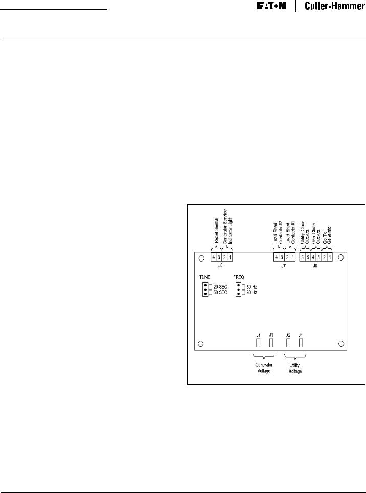
Figure 1. RTC-50 Connectors and Programming Jumpers.
2.4 Input/Output Connectors
Located along the bottom of the RTC-50 are connectors J1, J2, J3, and J4. J1 and J2 provide for voltage monitoring of utility. J3 and J4 provide for voltage monitoring of the generator.
Located along the top of the RTC-50 are connectors J6, J7, and J8. J6 provides connections for the control input and the transfer switch control outputs. J7 provides load shedding connections for the customer to use. J8 provides connections to a remote light to indicate that generator service is due. A pushbutton can be wired to the Reset Switch input to acknowledge and reset the Generator Service indication.
For more information visit: www.eaton.com |
IB00405004E-70-8664 |

Instructional Booklet
Instruction Manual for the Eaton RTC-50 Automatic Transfer Switch Controller
Effective: June 2007 |
Page 5 |
2.5 Go To Generator Input
The RTC-50 has a control input signal that will initiate a transfer from Utility to Generator. The input requires an external contact closure to the Go To Generator input (J6, pins 1 and 2).
The Control Input “State” definitions are as follows.
Connected - When the input is shorted by an external contact or connection.
Unconnected - When the input is NOT shorted by an external contact or connection.
The Go To Generator Input operations are defined as follows.
When this input (J6, pins 1 and 2) is in the “Connected” state, the RTC-50 will initiate a transfer from Utility to Generator. The Generator must be manually started or the Utility sensing wires must be interrupted in order to initiate an engine start. After the Generator becomes available, TDNE will time out before the transfer to Generator takes place. Re-transfer will occur when the external contact is opened or under a failsafe condition.
2.6 Output Connections
The RTC-50 output connections are divided into two categories:
•Customer Connections
•Transfer Operation Connections.
2.6.1 Customer Connections Load Shed Contacts
There are two sets of load shed contacts for customer use on connector J7, Load Shed Contacts #1 and Load Shed Contacts #2. Both sets of contacts are closed when the transfer switch is in the Utility position and both sets are open when the transfer switch is in the Generator position. The output contacts are rated for 5 amps @ 250 VAC. The DC rating is 5 amps @ 30 VDC.
Generator Service Indicator Light
The Generator Service Indicator Light is wired to connector J8, pins 1 and 2. A 5mm panel-mount LED with a maximum current rating of 25 mA is recommended (Dialight 559-5101-007F or equivalent). The LED can be located up to 1000 feet away from the RTC-50.
The LED is polarity sensitive. The red lead must be wired to J8, pin 1 and the black lead must be wired to J8, pin 2. If the wiring is reversed, the LED will not light.
The RTC-50 will track the number of hours that the generator has run. It will then turn on the Generator Service Indicator light to indicate that routine maintenance is required for every 25 hours that the generator has run. This will constitute one maintenance cycle.
The RTC-50 will keep track of the number of hours that the generator has run for up to 1000 hours. At this point, the counter will roll over and start again. The information is stored in non-volatile memory so that the value is retained when there is a loss of power.
The end-user will press the Gen Service Reset Switch to retrieve the generator run time information. The indicator will flash both long and short flashes to indicate the number of hours the generator has run. Each long flash (1 second) of the indicator equals 100 hours of run time and each short flash (0.2 second) equals 25 hours of run time.
Generator Service Reset Switch
The Generator Service Reset Switch is wired to connector J8, pins 3 and 4. A momentary single-pole, single-throw (SPST) pushbutton with normally open (N.O.) contacts is recommended (Judco 40-4313-00 or equivalent). The contact rating must be at least 50 mA at 24 V. When the pushbutton is pressed, the contacts will close across J8, pins 3 and 4. The pushbutton can be located up to 1000 feet away from the RTC-50.
The Generator Service Reset Switch will enable the end-user to retrieve information via the Generator Service Indicator Light indicating the number of hours that the generator has run. The Generator Service Indicator Light will flash long (1 second) flashes for each 100-hour interval and short (0.2 second) flashes for each 25hour interval in that order. The Generator Service Reset Switch may be pressed at any time to retrieve the Generator run time information to the nearest 25 hours.
For example, a Generator run time of 450 hours would be shown as four 100-hour long flashes of 1 second each followed by two 25-hour short flashes of 0.2 seconds each.
Pressing the Generator Service Reset Switch will also turn off the Generator Service Indicator Light if it had been lit.
2.6.2 Transfer Operations Connections
The Utility Close and Gen Close outputs are factory wired to operate the transfer switch. The relay contacts for each output are rated for 5 amps @ 250 VAC. The DC rating is 5 amps @ 30 VDC.
Utility Close Outputs
This output is used to transfer to Utility. The Utility Close Outputs are on J6, pins 5 and 6.
Generator Close Outputs
This output is used to transfer to Generator. The Generator Close Outputs are on J6, pins 3 and 4.
IB00405004E-70-8664 |
For more information visit: www.eaton.com |

Instructional Booklet
Page 6 |
Effective: June 2007 |
Instruction Manual for the Eaton RTC-50 Automatic Transfer Switch Controller
2.7 Specification Summary
Table 1. RTC-50 Controller Specifications
INPUT VOLTAGE |
240 VAC |
50/60 HZ |
Voltage Measurements of |
Utility |
Generator |
|
|
|
Voltage Measurement Range |
0 to 300 Vac RMS (50/60 Hz) |
|
|
|
|
Voltage Measurement Accuracy |
± 6 Vac |
|
|
|
|
Undervoltage Dropout |
70% of the Nominal 240 Vac Input Voltage |
|
|
|
|
Undervoltage Pickup |
80% of the Nominal 240 Vac Input Voltage |
|
|
|
|
Operating Temperature Range |
-20 to +70°C (-4 to +158°F) |
|
|
|
|
Storage Temperature Range |
-30 to +85°C (-22 to +185°F) |
|
|
|
|
Operating Humidity |
0 to 95% Relative Humidity (Non-condensing) |
|
|
|
|
Operating Environment |
Resistant to Ammonia, Methane, Nitrogen, Hydrogen, |
|
|
and Hydrocarbons |
|
|
|
|
Utility Close and Gen Close Outputs |
5 amps @ 250 Vac |
|
|
5 amps @ 30 Vdc |
|
|
|
|
Load Shed Contacts #1 and #2 |
5 amps @ 250 Vac |
|
|
5 amps @ 30 Vdc |
|
Applicable Testing |
UL Recognized Component |
|
|
UL 1008, UL 991 Environmental |
|
IEC 61000-4-2, 61000-4-3, 61000-4-4, 61000-4-5, 61000-4-6, 61000-4-11
CISPR 11, Class B FCC Part 15, Class B
SECTION 3: OPERATION
3.1 General
This section specifically describes the operation and functional use of the RTC-50 controller. The practical use of and operation within each category will be discussed. In this section, it is assumed that prior sections of this manual were reviewed and that the operator has a basic understanding of the hardware.
The RTC-50 controller provides for automatic transfer and retransfer from source to source. It provides a summary of the RTC-50 controller intelligence and supervisory circuits that constantly monitor the condition of both the Utility and Generator power sources, thus providing the required intelligence for transfer operations. These circuits, for example, automatically initiate an immediate transfer of power when the power fails or the voltage level drops below a preset value and an alternate source of power is available.
3.2 Operating Voltage and Measurements
The RTC-50 controller operates on an input voltage of 240 Vac with selectable frequency settings of 50 or 60 Hz.
The RTC-50 controller operates directly from the line sensing inputs of the Utility and Generator power sources.
All voltage monitoring and measurements are true RMS measurements.
3.3 Typical Transfer Operation
A typical transfer request will begin with a Utility outage (Utility voltage falls below the 70% dropout level).
When the Generator source meets the requirements to be considered available, the TDNE (Time Delay Normal to Emergency) timer will start timing. TDNE is jumper-programmable at either 20 seconds or 50 seconds. The 50 second setting may be used to allow for a longer warm-up period of the Generator. After TDNE times out, the Utility Close Outputs will open, the Gen Close Outputs will close, and the Load Shed Contacts will open. This will connect the load to the Generator source but any loads wired to the Load Shed Contacts will be disconnected.
When the Utility becomes available (Utility voltage is above the 80% pickup level), the TDEN (Time Delay Emergency to Normal) timer will start timing. TDEN is a fixed delay of 10 seconds. After TDEN times out, the Gen Close Outputs will open, the Utility Close Outputs will close, and the Load Shed Contacts will be closed. This will connect all loads to the Utility source.
For more information visit: www.eaton.com |
IB00405004E-70-8664 |
Instructional Booklet
Instruction Manual for the Eaton RTC-50 Automatic Transfer Switch Controller
Effective: June 2007 |
Page 7 |
SECTION 4: PROGRAMMING
4.1 Introduction
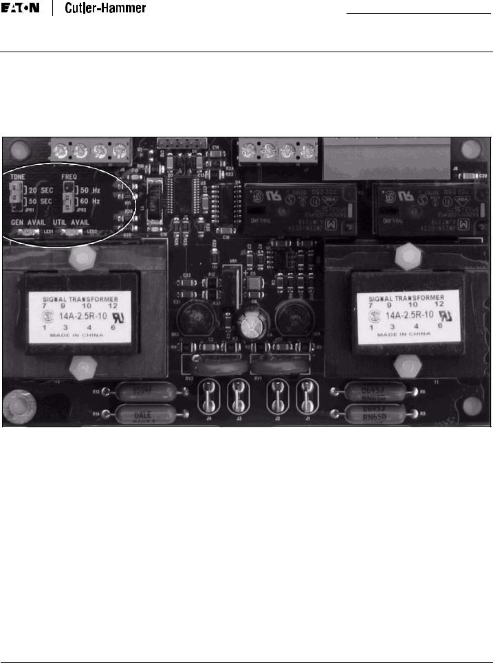
The RTC-50 controller is programmable via the two programming jumpers shown in Figure 2.
The TDNE jumper enables the end-user to select a Time Delay Normal to Emergency setting of either 20 seconds or 50 seconds.
TDNE is a time delay that starts timing when the Generator source becomes available either after the Utility becomes unavailable or after the Go To Generator input is activated. The 50 second setting may be used to allow for a longer warm-up period of the Generator.
The FREQ jumper enables the end-user to program the RTC-50 for an operating frequency of either 50 or 60 hertz.
Figure 2. RTC-50 Programming Jumpers.
Table 2 is a summary of the Fixed and Jumper-selectable settings that are available in the RTC-50.
Table 2. Fixed and Jumper-Selectable Settings
DESCRIPTION |
RANGE |
FACTORY DEFAULT |
FIXED/JUMPER |
|
|
|
|
Time Delay Normal to Emergency |
20 or 50 seconds |
20 seconds |
Jumper-selectable |
|
|
|
|
Time Delay Emergency to Normal |
10 seconds |
10 seconds |
Fixed setting |
|
|
|
|
Time Delay Emergency Fail Timer |
6 seconds |
6 seconds |
Fixed setting |
|
|
|
|
Nominal Frequency |
50 or 60 Hz |
60 Hz |
Jumper-selectable |
|
|
|
|
Nominal Voltage |
240 Vac |
240 Vac |
Fixed setting |
|
|
|
|
Utility Undervoltage Dropout |
70% of 240 Vac Nominal Voltage |
70% of 240 Vac Nominal Voltage |
Fixed setting |
|
|
|
|
Generator Undervoltage Dropout |
70% of 240 Vac Nominal Voltage |
70% of 240 Vac Nominal Voltage |
Fixed setting |
|
|
|
|
Utility Undervoltage Pickup |
80% of 240 Vac Nominal Voltage |
80% of 240 Vac Nominal Voltage |
Fixed setting |
|
|
|
|
Generator Undervoltage Pickup |
80% of 240 Vac Nominal Voltage |
80% of 240 Vac Nominal Voltage |
Fixed setting |
|
|
|
|
IB00405004E-70-8664 |
For more information visit: www.eaton.com |

Instructional Booklet
Page 8 |
Effective: June 2007 |
Instruction Manual for the Eaton RTC-50 Automatic Transfer Switch Controller
SECTION 5: MAINTENANCE, TROUBLESHOOTING, AND REPLACEMENT
5.1 Maintenance and Care
The RTC-50 is designed to be a self-contained and maintenancefree unit. The printed circuit board is conformally coated at the factory. The RTC-50 is intended for service by factory-trained personnel only.
Step 7: Reconnect the wires to J7 and J8. Step 8: Reapply power to the transfer switch.
Step 9: Place the generator control selector switch in the “AUTO” position after the controller has been replaced. (The Generator may start but will shut down within 5 minutes.)
Test the system for proper functionality.
5.2 RTC-50 Controller Troubleshooting
The Troubleshooting Guide (Table 3) is intended for service personnel to identify whether a problem being observed is external or internal to the unit. For assistance with this determination, contact Eaton Electrical. If a problem is identified to be internal, the unit should be returned to the factory for replacement.
Table 3. Troubleshooting Guide.
SYMPTOM |
PROBABLE CAUSE |
POSSIBLE SOLUTION(S) |
“Util Avail” and “Gen Avail” |
Power is deficient or absent. |
Verify that power is connected |
LEDs are not lit. |
|
at J1 – J4 and that it is within |
|
|
specifications. |
|
RTC-50 is malfunctioning. |
Replace the unit. |
|
|
|
Utility source or Generator |
Voltage is not within setpoint |
Verify voltage with multimeter. |
source is not available when |
values. |
Check the programmed setpoint |
it should be. |
|
values. |
5.3 Level of Repair
This manual is written with the assumption that only ATS troubleshooting will be performed. If the cause of malfunction is traced to an RTC-50, the unit should be replaced with a new unit. The malfunctioning unit should then be returned to Eaton Electrical for factory repairs.
5.4 RTC-50 Replacement
 WARNING
HIGH VOLTAGES ARE PRESENT IN AND AROUND TRANSFER SWITCH EQUIPMENT. BEFORE ATTEMPTING TO REPLACE ANY COMPONENT, DISCONNECT THE LINE POWER FROM THE EQUIPMENT BEING SERVICED BY OPENING AND LOCKING OUT, IF POSSIBLE, THE NEXT HIGHEST DISCONNECT DEVICE. FAILURE TO FOLLOW THIS PROCEDURE COULD CAUSE SEVERE PERSONAL INJURY AND/OR DEATH.
ALWAYS TURN THE UTILITY POWER OFF AND TURN THE GENERATOR CONTROL SELECTOR SWITCH TO THE “OFF” POSITION BEFORE ATTEMPTING TO REPLACE ANY COMPONENTS.
Step 1: Turn the Generator Start select to “OFF” before attempting to replace the RTC-50 controller. Ensure all sources of power are removed.
Step 2: Disconnect the J1, J2, J3, J4, and J6 plugs from the controller
Step 3: Disconnect the wires connected to J7 and J8.
Step 4: Remove the four (4) screws located at the corners of the controller that secure it to the power panel. Remove the controller.
Step 5: Align the new controller with the mounting holes. Secure the new controller board using the existing hardware. Tighten the screws.
Step 6: Connect the J1, J2, J3, J4, and J6 plugs to their original receptacles.
For more information visit: www.eaton.com |
IB00405004E-70-8664 |
Instructional Booklet
Instruction Manual for the Eaton RTC-50 Automatic Transfer Switch Controller
Effective: June 2007 |
Page 9 |
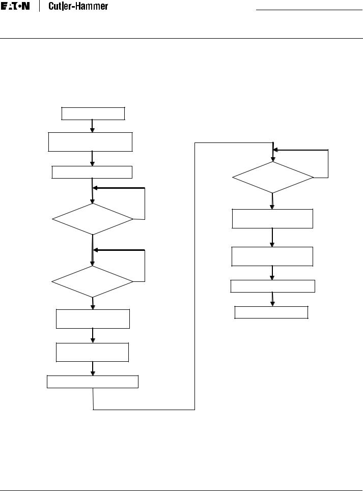
APPENDIX A: OPERATIONAL FLOWCHART
Utility is available
ATS connects to Utility
(Utility Close Output closes)
Utility is powering the load
Is Utility |
Y |
available? |
|
N |
|
Is Generator |
N |
|
|
available? |
|
Y |
|
TDNE timer times out |
|
(20 sec or 50 sec) |
|
N
Is Utility available yet?
Y
TDEN timer times out (10 sec)
Transfer to Utility
(Utility Close Output closes)
Utility is powering the load
Generator shuts down
Transfer to Generator
(Gen Close Output closes)
Generator is powering the load
IB00405004E-70-8664 |
For more information visit: www.eaton.com |

Instructional Booklet
Page 10 |
Effective: June 2007 |
Instruction Manual for the Eaton RTC-50 Automatic Transfer Switch Controller
Notes
For more information visit: www.eaton.com |
IB00405004E-70-8664 |
Instructional Booklet
Instruction Manual for the Eaton RTC-50 Automatic Transfer Switch Controller
Effective: June 2007 |
Page 11 |
Notes:
IB00405004E-70-8664 |
For more information visit: www.eaton.com |
Loading...