


Vickers®
Piston Pumps
Overhaul Manual
PVE Variable Pump
12–21 USgpm capacity at 1800 rpm
Released 8/1/90 |
M-2854-S |

Table of Contents |
|
Section |
Page |
I. Introduction . . . . . . . . . . . . . . . . . . . . . . . . . . . . . . . . . . . . . . . . . . . . . . . . . . . . . . . . . . . . . . . . . . . . . . . . . . . . . . . . . . |
. . 3 |
A. Purpose of Manual . . . . . . . . . . . . . . . . . . . . . . . . . . . . . . . . . . . . . . . . . . . . . . . . . . . . . . . . . . . . . . . . . . . . . . . . . . |
. . 3 |
B. General Information (Related Publications/Model Code) . . . . . . . . . . . . . . . . . . . . . . . . . . . . . . . . . . . . . . . . . . . . . |
. . 3 |
II. Description . . . . . . . . . . . . . . . . . . . . . . . . . . . . . . . . . . . . . . . . . . . . . . . . . . . . . . . . . . . . . . . . . . . . . . . . . . . . . . . . . . . |
. . 6 |
A. General . . . . . . . . . . . . . . . . . . . . . . . . . . . . . . . . . . . . . . . . . . . . . . . . . . . . . . . . . . . . . . . . . . . . . . . . . . . . . . . . . . . |
. . 6 |
B. Application . . . . . . . . . . . . . . . . . . . . . . . . . . . . . . . . . . . . . . . . . . . . . . . . . . . . . . . . . . . . . . . . . . . . . . . . . . . . . . . . |
. . 6 |
III. Principles of Operation . . . . . . . . . . . . . . . . . . . . . . . . . . . . . . . . . . . . . . . . . . . . . . . . . . . . . . . . . . . . . . . . . . . . . . . . . . . 7 A. Piston Pump . . . . . . . . . . . . . . . . . . . . . . . . . . . . . . . . . . . . . . . . . . . . . . . . . . . . . . . . . . . . . . . . . . . . . . . . . . . . . . . . . 7 B. Compensator (Flat Cut-Off Type - “C”). . . . . . . . . . . . . . . . . . . . . . . . . . . . . . . . . . . . . . . . . . . . . . . . . . . . . . . . . . . . . 7 C. Compensator (Remote Control Type - “CG”). . . . . . . . . . . . . . . . . . . . . . . . . . . . . . . . . . . . . . . . . . . . . . . . . . . . . . . . 7 D. Compensator (Load Sensing Type - “CV”). . . . . . . . . . . . . . . . . . . . . . . . . . . . . . . . . . . . . . . . . . . . . . . . . . . . . . . . . . 8
E. Compensator (Load Sensing with Pressure Limiting - “CVP”, “CVPC”, “CVPD”). . . . . . . . . . . . . . . . . . . . . . . . . . . . 10
IV. Installation and Operating Instructions . . . . . . . . . . . . . . . . . . . . . . . . . . . . . . . . . . . . . . . . . . . . . . . . . . . . . . . . . . . . . . 12 A. Installation Drawings . . . . . . . . . . . . . . . . . . . . . . . . . . . . . . . . . . . . . . . . . . . . . . . . . . . . . . . . . . . . . . . . . . . . . . . . . . 12 B. Mounting and Drive Connections . . . . . . . . . . . . . . . . . . . . . . . . . . . . . . . . . . . . . . . . . . . . . . . . . . . . . . . . . . . . . . . . 12 C. Shaft Rotation . . . . . . . . . . . . . . . . . . . . . . . . . . . . . . . . . . . . . . . . . . . . . . . . . . . . . . . . . . . . . . . . . . . . . . . . . . . . . . . 12 D. Piping and Tubing . . . . . . . . . . . . . . . . . . . . . . . . . . . . . . . . . . . . . . . . . . . . . . . . . . . . . . . . . . . . . . . . . . . . . . . . . . . . 12 E. Hydraulic Fluid Recommendations . . . . . . . . . . . . . . . . . . . . . . . . . . . . . . . . . . . . . . . . . . . . . . . . . . . . . . . . . . . . . . . 12 F. Overload Protection . . . . . . . . . . . . . . . . . . . . . . . . . . . . . . . . . . . . . . . . . . . . . . . . . . . . . . . . . . . . . . . . . . . . . . . . . . 13 G. Start–up . . . . . . . . . . . . . . . . . . . . . . . . . . . . . . . . . . . . . . . . . . . . . . . . . . . . . . . . . . . . . . . . . . . . . . . . . . . . . . . . . . . 13
V. Service and Maintenance . . . . . . . . . . . . . . . . . . . . . . . . . . . . . . . . . . . . . . . . . . . . . . . . . . . . . . . . . . . . . . . . . . . . . . . . 14 A. Service Tools . . . . . . . . . . . . . . . . . . . . . . . . . . . . . . . . . . . . . . . . . . . . . . . . . . . . . . . . . . . . . . . . . . . . . . . . . . . . . . . 14 B. Inspection . . . . . . . . . . . . . . . . . . . . . . . . . . . . . . . . . . . . . . . . . . . . . . . . . . . . . . . . . . . . . . . . . . . . . . . . . . . . . . . . . . 14 C. Adding Fluid to the System . . . . . . . . . . . . . . . . . . . . . . . . . . . . . . . . . . . . . . . . . . . . . . . . . . . . . . . . . . . . . . . . . . . . . 14 D. Adjustments . . . . . . . . . . . . . . . . . . . . . . . . . . . . . . . . . . . . . . . . . . . . . . . . . . . . . . . . . . . . . . . . . . . . . . . . . . . . . . . . 14 E. Lubrication . . . . . . . . . . . . . . . . . . . . . . . . . . . . . . . . . . . . . . . . . . . . . . . . . . . . . . . . . . . . . . . . . . . . . . . . . . . . . . . . . 14 F. Replacement Parts . . . . . . . . . . . . . . . . . . . . . . . . . . . . . . . . . . . . . . . . . . . . . . . . . . . . . . . . . . . . . . . . . . . . . . . . . . . 16 G. Troubleshooting . . . . . . . . . . . . . . . . . . . . . . . . . . . . . . . . . . . . . . . . . . . . . . . . . . . . . . . . . . . . . . . . . . . . . . . . . . . . . 17
VI. Overhaul . . . . . . . . . . . . . . . . . . . . . . . . . . . . . . . . . . . . . . . . . . . . . . . . . . . . . . . . . . . . . . . . . . . . . . . . . . . . . . . . . . . . . 18 A. General . . . . . . . . . . . . . . . . . . . . . . . . . . . . . . . . . . . . . . . . . . . . . . . . . . . . . . . . . . . . . . . . . . . . . . . . . . . . . . . . . . . 18 B. Disassembly . . . . . . . . . . . . . . . . . . . . . . . . . . . . . . . . . . . . . . . . . . . . . . . . . . . . . . . . . . . . . . . . . . . . . . . . . . . . . . . . 18 C. Inspection, Repair and Replacement . . . . . . . . . . . . . . . . . . . . . . . . . . . . . . . . . . . . . . . . . . . . . . . . . . . . . . . . . . . . . 18 D. Assembly of Compensator . . . . . . . . . . . . . . . . . . . . . . . . . . . . . . . . . . . . . . . . . . . . . . . . . . . . . . . . . . . . . . . . . . . . . 23 E. Removal and Disassembly of Rotating Group . . . . . . . . . . . . . . . . . . . . . . . . . . . . . . . . . . . . . . . . . . . . . . . . . . . . . . 23 F. Inspection, Repair and Replacement . . . . . . . . . . . . . . . . . . . . . . . . . . . . . . . . . . . . . . . . . . . . . . . . . . . . . . . . . . . . . 24 G. Assembly of Housing Parts . . . . . . . . . . . . . . . . . . . . . . . . . . . . . . . . . . . . . . . . . . . . . . . . . . . . . . . . . . . . . . . . . . . . 26 H. Disassembly of Valve Block . . . . . . . . . . . . . . . . . . . . . . . . . . . . . . . . . . . . . . . . . . . . . . . . . . . . . . . . . . . . . . . . . . . . 28 I. Inspection, Repair and Replacement . . . . . . . . . . . . . . . . . . . . . . . . . . . . . . . . . . . . . . . . . . . . . . . . . . . . . . . . . . . . 28 J. Assembly of Valve Block . . . . . . . . . . . . . . . . . . . . . . . . . . . . . . . . . . . . . . . . . . . . . . . . . . . . . . . . . . . . . . . . . . . . . . 28 K. Shaft Bearing Preload Adjustment . . . . . . . . . . . . . . . . . . . . . . . . . . . . . . . . . . . . . . . . . . . . . . . . . . . . . . . . . . . . . . . 29 L. Final Assembly of PVE Series Pump . . . . . . . . . . . . . . . . . . . . . . . . . . . . . . . . . . . . . . . . . . . . . . . . . . . . . . . . . . . . . 29
VII.Test Procedure . . . . . . . . . . . . . . . . . . . . . . . . . . . . . . . . . . . . . . . . . . . . . . . . . . . . . . . . . . . . . . . . . . . . . . . . . . . . . . . . . 30 A. Test Conditions . . . . . . . . . . . . . . . . . . . . . . . . . . . . . . . . . . . . . . . . . . . . . . . . . . . . . . . . . . . . . . . . . . . . . . . . . . . . . . 30 B. Preliminary Check . . . . . . . . . . . . . . . . . . . . . . . . . . . . . . . . . . . . . . . . . . . . . . . . . . . . . . . . . . . . . . . . . . . . . . . . . . . . 30 C. Preliminary Set–Up . . . . . . . . . . . . . . . . . . . . . . . . . . . . . . . . . . . . . . . . . . . . . . . . . . . . . . . . . . . . . . . . . . . . . . . . . . . 30 D. Performance Test . . . . . . . . . . . . . . . . . . . . . . . . . . . . . . . . . . . . . . . . . . . . . . . . . . . . . . . . . . . . . . . . . . . . . . . . . . . . 30
E. Performance Test of Piston Pump with “C” Compensator Control. . . . . . . . . . . . . . . . . . . . . . . . . . . . . . . . . . . . . . . 30 F. Performance Test of PVE 12/19/21 Piston Pump with “CG” Compensator Control. . . . . . . . . . . . . . . . . . . . . . . . . . 31 G. Performance Test of PVE 12/19/21 Piston Pump with “CV”, “CVP”, “CVPC” and “CVPD” Compensator Control. . . 32
H. Load Sensing Control Test . . . . . . . . . . . . . . . . . . . . . . . . . . . . . . . . . . . . . . . . . . . . . . . . . . . . . . . . . . . . . . . . . . . . . 32
2
Section I – Introduction
A. Purpose Of Manual
This manual describes operational characteristics and overhaul information for the PVE12, 19(*) and the PVE21(*)–** variable displacement piston pumps. The information contained herein pertains to the latest design series as listed in Table 1.
B.General Information
1.Related Publications - Service parts information and installation dimensions are not contained in this manual. The parts and installation drawings listed in Table 1 are available from authorized distributors or sales engineers.
|
Model |
Parts |
Installation |
|
Series |
Drawing |
Drawing |
|
|
|
|
|
PVE12 |
M-2853-G |
_____ |
|
|
||
|
PVE19 |
M-2841-S |
322C |
|
PVE21 |
||
|
|
|
|
|
|
Table 1. |
|
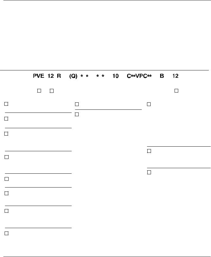
2. Model Codes - Variations within each basic model series are covered in the model code. Table 2 shows a complete breakdown of the model codes covering these units. Service inquiries should always include the complete model code number as stamped on the mounting flange.
|
|
|
|
|
|
|
|
|
|
|
|
|
|
|
|
|
|
|
|
|
|
|
|
|
|
|
|
|
|
|
|
|
|
|
|
|
|
|
|
|
|
|
|
|
|
|
|
|
|
|
|
|
|
|
|
|
|
|
|
|
|
|
|
|
|
|
|
|
|
|
|
|
|
|
|
|
|
|
|
|
|
|
|
|
|
|
|
|
|
|
|
|
|
|
|
|
|
|
|
|
|
|
|
|
|
|
|
|
|
|
|
|
|
|
|
|
|
|
|
|
|
|
|
|
|
|
|
|
|
|
|
|
|
|
|
|
|
|
|
|
|
|
|
|
|
|
|
|
|
|
|
|
|
|
|
|
|
|
|
|
|
|
|
|
1 |
2 |
|
3 |
|
|
|
|
4 |
|
|
5 |
|
6 |
|
|
|
7 |
|
8 |
|
|
|
|
9 |
|
|
|
|
|
10 |
|
|
|
|
11 |
12 |
|
|||||||||||||||||
|
|
|
|
|
|
|
|
|
|
|
|
|
|
|
|
|
|
|
|
|
|
|
|
|
|
|
|
|
|
|
|
|
|
|
|
|
|
|
|
|
|
|
|
|
|
|
|
|
|
|
|
|
|
|
1Pump, Variable Displacement, Inline Piston, E-Series
2Flow Rating
USgpm @ 1800 rpm
3Shaft Rotation
(Viewed from shaft end)
R – Right hand (clockwise)
L – Left hand (counterclockwise)
4Noise Level Rating Blank – Standard Unit Q – Industrial Quieter
1800 rpm @ 207 bar (3000 psi)
5Mounting Flange B – SAE B 2 bolt
6Input Shaft Type
1 – SAE B Straight keyed
2 – SAE B Splined
7Port Configuration
E – End ported, SAE O-ring M – End ported, metric O-ring (per ISO 6149)
8Shaft Seal
S – Standard shaft seal N – No shaft seal
9 Design
10Control Options
(** = Pressure setting in tens of bars)
C** – Pressure compensator Max. setting 207 bar (3000 psi)
Range 02-21 bar C**VP** – Pressure & load sensing
Pressure compensating (see C**)
Load sensing (see CV**) C**VPC** –Pressure and load sensing
Pressure compensating (see C**)
Load setting 24 bar (350 psi)
Range 17-31 bar (251-450 psi)
C**VPD** –Pressure & load sensing Pressure compensating (see C**)
Load setting 41 bar (600 psi)
Range 32-45 bar (451-650 psi)
Same as C** except with max. adj. stop.
Pressure compensation with remote control (see C**)
Electric dual range compensation
Same as CD except with max. adj. stop
10Control Options (Con’t)
(** = Pressure setting in tens of bars)
CC** - Same as C** except with max. adj. stop.
CG**- Pressure compensation with remote control (see C**) Electric dual range com-
CD - pensation
Same as CD except with CCD - max. adj. stop
11Control Bleed Down
Blank – C, CC, CG, CD, CCD
B – Bleed down orifice (CVP & CVPC) P – Plug (no orifice) (CVP & CVPC)
12Control Design
Table 2. Model Code Breakdown
3
|
|
|
|
|
|
|
|
|
|
|
|
|
|
|
|
|
|
|
|
|
|
|
|
|
|
|
|
|
|
|
|
|
|
|
|
|
|
|
|
|
|
|
|
|
|
|
|
|
|
|
|
|
|
|
|
|
|
|
|
|
|
|
|
|
|
|
|
|
|
|
|
|
|
|
|
|
|
|
|
|
|
|
|
|
|
|
|
|
|
|
|
|
|
|
|
|
|
|
|
|
|
|
|
|
|
|
|
|
|
|
|
|
|
1 |
2 |
|
3 |
|
4 |
|
|
|
5 |
|
|
|
|
6 |
7 |
|
8 |
|
|||||||||||||||||||
|
|
|
|
|
|
|
|
|
|
|
|
|
|
|
|
|
|
|
|
|
|
|
|
|
|
|
|
|
|
|
|
|
|
|
|
|
|
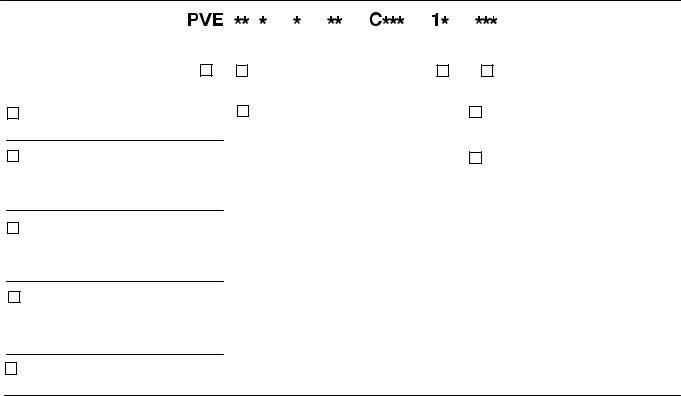
1Pump, Variable Displacement, Inline Piston, E–Series
2Flow Rating
USgpm @ 1800 rpm 19 – 19 USgpm
21 – 21 USgpm
3Shaft Rotation
(Viewed from shaft end)
R – Right hand (clockwise)
L – Left hand (counterclockwise)
4Input Shaft Type
1 – SAE B Straight keyed
2 – SAE B 15 tooth splined
9 – SAE B 13 tooth spline
5 Pump Design
6 Control Options |
7 |
Control Design |
|
(** = Pressure setting in tens of bars) |
|
|
|
C-10 – |
Pressure compensated |
|
|
|
Special Suffix |
||
|
(PVE19, 250-3000 psi) |
8 |
|
CG-10 – |
(PVE21, 250-2700 psi) |
|
|
Remote control pressure |
|
|
|
|
compensator adjustable |
|
|
|
from 350-3000 psi using |
|
|
CV-10 – |
and external relief valve. |
|
|
Load sensing PVE19/21 |
|
|
|
CVP-12 – |
Load sensing (160 psid) |
|
|
|
with pressure compensation |
|
|
|
PVE 19/21 |
|
|
CVPC-12 –Load sensing (350 psid) with pressure compensation PVE 19/21
Table 2. Model Code Breakdown (Con’t)
4

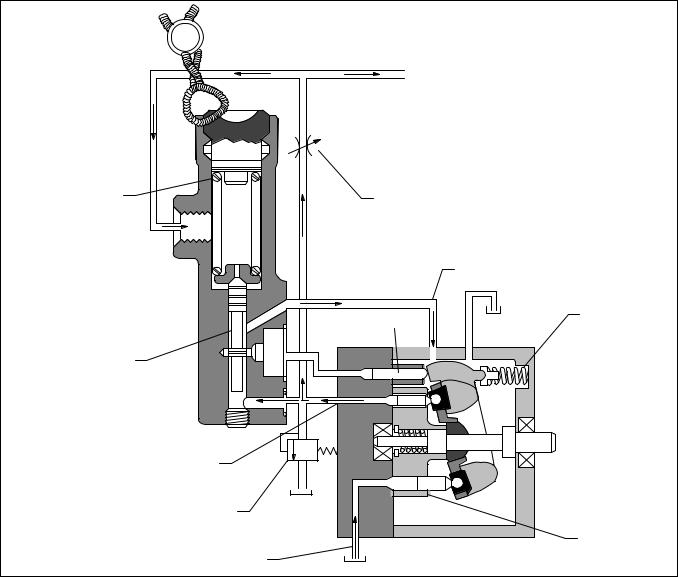
|
Housing |
Compensator |
|
|
|
Shaft |
Yoke |
|
|
|
|
Seal |
|
|
Shaft
|
Bearing |
Piston |
Valve Block |
|
|
||
|
PVE12 Section View |
|
|
Yoke |
Wafer Plate |
|
Compensator |
|
|
||
Tapered
Roller
Bearing
Drive
Shaft
Housing
Rotating Group
PVE19 Section View
Figure 1. Sectional Views of the PVE Pumps
5
Section II – Description
A. General
Assembly of a typical pump package is shown in Figure 1.
Six types of compensator subassemblies are used with the PVE series pumps. Refer to Section III for principles of operation. See Model Code for pressure settings.
1.Compensator (C), (Flat Cut-Off Type): A pump using this compensator will maintain a constant load pressure for all values of flow within the capacity of the pump.
2.Compensator (CG), (Remote Control Type): This compensator is similar to the “C” type compensator except the compensator is controlled by a remote hydraulic source such as a relief valve.
3.Compensator (CV), (Load Sensing Type): A load sensing compensator provides flow at a pressure equal to that required by the load plus a constant value used as a pressure drop across a metering valve. The pump will change its flow with changes in size of the metering valve orifice. The pump and compensator together provide a constant flow source for the load, at a pressure established by the requirements of the load, hence the title “Load Sensing”.
CAUTION
A relief valve must be provided in the external circuit to prevent excessive pressure build up at the pump.
4.Compensator (CVP), (Load Sensing Pressure Limiting Type): The CVP control is a combination of the standard flat cut-off compensator (C) and the load sensing compensator (CV). The load sensing compensator controls flow to the load across an external valve orifice. If pressure build–up exceeds the flat cut-off compensator setting, the flat cut-off compensator overrides the load sensing compensator and lowers the flow to prevent excessive pressure build-up at the pump.
5.Compensator (CVPC), (Load Sensing Pressure Limiting Type): This compensator is the same as the “CVP” compensator except the load sensing spring is heavier. The heavier spring provides a slightly higher pressure differential (160nP vs. 350nP) across the external valve orifice. See Figure 5.
6.Compensator (CVPD), (Load Sensing, Pressure Limiting Type): Same as “CVPC” except with higher pressures.
B.Application
Pump ratings in USgpm as shown in the model coding are at 1800 rpm. For ratings at other speeds, methods of installation and other application information, contact an authorized distributor or sales engineer.
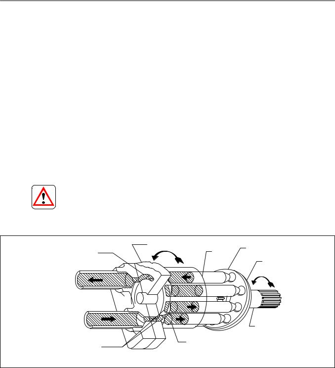
Outlet Wafer Plate |
Wafer Plate |
|
Shoe Plate |
||
Kidney Slot |
Piston |
|
Yoke Face |
||
|
||
Outlet Port |
|
Inlet Port
Drive Shaft
Cylinder
Intake Kidney Block Bore
Slot Area
Figure 2.
6

Section III – Principles of Operation
A. Piston Pump
Rotation of the pump drive shaft causes the cylinder block, shoe plate and pistons to rotate. See Figure 2. The piston shoes are held against the yoke face by the shoe plate. The angle of the yoke face imparts a reciprocating motion to each piston within the cylinder block. Inlet and outlet ports connect to a kidney slotted wafer plate. As the pistons move out of the cylinder block, a vacuum is created and fluid is forced into the void by atmospheric pressure. The fluid moves with the cylinder block past the intake kidney slot to the outlet (pressure) kidney slot. The motion of the piston reverses and fluid is pushed out the cylinder block into the outlet port.
B. Compensator (Flat Cut-Off Type)
A flat cut-off compensated pump will maintain a constant load pressure for all values of flow within the capacity of the pump providing the load is sufficient to build up pressure.
A step by step description of the flat cut-off type compensator control follows. Refer to Figure 3 throughout this discussion.
When a no load condition exists, the pump will deliver maximum flow at zero pressure. As the actuator load increases, pressure will rise; however, flow will remain at maximum until pressure reaches the compensator spring setting (cracking pressure). As a further increase in load occurs, system pressure will cause the compensator spool to move against the compensator spring, metering flow to the yoke stroking piston. The yoke stroking piston then moves the yoke to reduce flow. As flow is reduced, system pressure reduces slightly causing the compensator spool to return to the null position. At null, flow to the yoke stroking piston stops. Movement of the yoke will stop and the flow will stabilize at a reduce value. If the load were to continue to increase, the pump flow will reduce to zero (0) and a deadhead pressure condition would exist. The pressure differential needed to cause the compensator spool to change from maximum flow (cracking pressure) to zero flow (deadhead pressure) is approximately 50 to 150 PSI.
Pump outlet flow is proportional to the control range from cracking pressure to deadhead pressure. (i.e. If cracking pressure is 2900 PSI (max. flow) and deadhead pressure is 3000 PSI (min. flow), a pressure of 2950 PSI would be equal to 1/2 maximum flow.)
If the load decreases, pressure will decrease proportionally and the compensator spring will move the spool down, opening the yoke stroking piston to case drain. As fluid is metered from the yoke stroking piston, the yoke spring will stroke the yoke to increase flow. The increase in flow causes a proportional increase in system pressure. The increase in system pressure returns the compensator spool to a null position and flow from the yoke stroking position will stop; simultaneously, movement of the yoke will stop. The flow will stay constant until another change of load occurs.
If the load continues to decrease, pump flow will continue too increase, holding the outlet at compensator cracking pressure. When maximum flow is reached (max. stroke), a maximum flow and a maximum pressure condition exists. A further decrease in load will lower the outlet pressure until a final theoretical condition of maximum flow and zero pressure is obtained.
C. Compensator (Remote Control - “CG”)
This compensator allows the operator to change the pressure setting through the use of a remote control valve. The “CG” compensator has the same performance characteristics as the “C” type compensator.
7
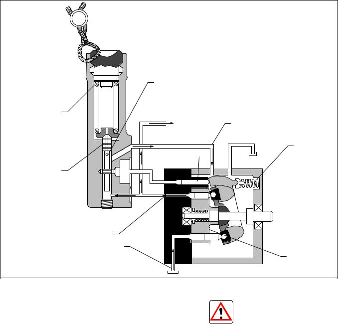
Cross Hole (Open to
Spring Area)
Compensator Spring
Pump Load |
Drain |
Yoke Spring
Yoke Stroking Piston
Compensator Spool
Outlet
Inlet
Rotating Group
Figure 3. Flat Cut-Off Compensator
D. Compensator
(Load Sensing Type - “CV”)
Application
A frequent application of pressure compensator pumps is to supply sevo valves or mechanically operated metering valves, whose function is to control flow to a hydraulic actuator (cylinder or motor).
In such circuits it is often desirable that flow be proportional only to an external valve spool position. This requires a constant pressure drop across the external valve. (NOTE: Flow through a valve varies with pressure drop as well as with valve spool position.)
Pumps incorporating the load sensing feature have a constant flow characteristic: Flow is constant regardless of the load pressure.
CAUTION
A relief valve must be used to prevent outlet pressure from exceeding pump ratings if the load is excessive.
Minimum Pump Pressure
The minimum outlet pressure developed by the pump (no load) is a function of the compensator spring force versus the yoke spring force, whichever is greater. (Please note that external valve spool position (orifice size), has nothing to do with the minimum outlet pressure of the pump). The orifice size controls pump rate of flow only. The minimum outlet pressure will be constant for all settings of the valve spool orifice and is considered the pressure drop across the orifice (nP).
8
Compensator Spring
Compensator Spool
Actuator
Load
External Valve
Spool Orifice
(nP-Pressure Drop)
Drain
Yoke Spring
Yoke Stroking Piston
Outlet
Relief
Valve
Rotating Group
Inlet
Figure 4. Load Sensing Compensator (CV).
Circuit Operation At Minimum Pressure
Refer to Figure 4 during the following description. Assume a no load condition.
The pump load consists of the pressure drop across the valve spool orifice (nP), plus the pressure developed by the work being performed at the actuator. (In this case the actuator is unloaded and only the pressure drop across the valve spool orifice (nP) will be considered.)
Flow is restricted through the valve spool orifice and develops a pressure at the outlet of the pump. This pressure is applied to the lower end of the compensator spool. Initially, the compensator spring is holding the spool in the down position and the yoke is at maximum delivery position. When the pump is started, the increasing flow increases pressure at the lower end of the compensator spool and the compensator spool opens pressure to the yoke stroking piston. The yoke then strokes to a lower flow, lowering the pressure drop across the external valve orifice. When pressure reaches nP, the compensator spool will null. At this time, the stroking piston will remain stable until the external valve spool orifice is changed. (See Figure 4.)
External Valve Spool Orifice Size Reduced
If the external valve spool orifice is reduced in size, pressure at the pump outlet will rise proportionally causing the compensator spool to move against the compensator spring. When the compensator spool moves far enough to open the yoke stroking piston to pump outlet pressure, the yoke stroking piston will move the yoke to a lower flow setting.
The compensator senses pressure at the downstream side of the external valve spool orifice and compares this pressure to the pump outlet pressure. The compensator then adjusts the yoke to a flow which holds a constant pressure drop (nP) across the external valve spool orifice.
The pressure developed at the pump outlet is a summation of the pressure drop across the external valve spool orifice and the actuator load pressure. As the actuator load pressure increases, the increase is reflected directly back to the pump outlet. Since the compensator monitors the difference between pump outlet pressure and actuator load pressure, and this difference (nP) does not change with load variations, flow from the pump will stay constant.
9

External Valve Spool Orifice Size Increased
If the external valve spool orifice size is increased, pump outlet pressure will decrease, lowering force against the compensator spool. (See Figure 4.) The compensator spring causes the spool to move, opening the yoke stroking piston to case drain. As fluid is metered from the yoke stroking piston, the yoke spring force strokes the yoke to a higher flow. The increase in flow through the external valve spool orifice establishes once again the constant pressure drop (nP). With differential pressure (nP) across the external valve orifice, the compensator spool nulls. Flow from the yoke stroking piston stops, and the pump flow rate stabilizes at a higher value.
Operation of the load sensing compensator is such that as the load pressure varies, the pump outlet pressure will follow the variations, holding a constant pressure drop (nP) across the external valve spool orifice, and a constant flow through the external valve and actuator. Pump flow will change only with changes in external valve spool orifice size.
E. Compensator (Load Sensing with Pressure
Limiting “CVP”, “CVPC”, “CVPD”)
As expected from the above title, these units are a combination of the flat cut-off and load sensing compensators.
The load sensing portion functions at pressures below the flat cut-off compensator setting and provides a constant flow characteristic. If pressure exceeds the flat cut-off compensator setting, the yoke will stroke to zero flow at maximum pressure lowering the horsepower requirements for holding circuits and protecting the pump. Refer to Figure 5 throughout the following circuit explanation.
Assume an actuator load that is increasing gradually. Also, assume the pump outlet pressure is lower than the flat cut-off compensator cracking pressure. As actuator load pressure increases, the load sensing compensator spool senses the difference between pump outlet pressure and actuator load pressure. As long as the difference between the pump outlet pressure and the actuator load pressure (nP) is constant, flow to the load will stay constant. As pressure rises across the load, leakage will increase in the pump and load. The load sensing portion of the compensator adjusts pump outlet flow to compensate for leakage while providing a constant flow through the valve spool orifice.
The pump outlet pressure continues to increase until the flat cut-off compensator spool reaches cracking pressure. The flat cut-off compensator spool then meters flow to the yoke stroking piston. The yoke stroking piston starts moving the yoke to reduce flow while holding the outlet pressure at compensator cracking pressure. This action continues until the pump is fully compensated (zero flow and maximum pressure).
Standby Operation Feature
Standby defined: When the external valve spool is shifted to zero flow, the circuit is placed in standby.
The small fixed orifice located in the compensator body provides a decompression feature for the load circuit during standby operation. The decompression feature allows the pump to stroke to zero flow and minimum pressure (nP), if the load is blocked and the external valve spool orifice is closed. (Refer to Figure 5.)
The circuit functions as follows:
Assume the pump is at zero flow with maximum pressure to the load. The flat cut-off compensator spool will be in the up position (compressing the spring) and the load sensing spool will be in the down position due to actuator load pressure plus the spring force. If the external valve spool orifice is closed at this time, fluid under pressure will be trapped in the load circuit and will hold the load sensing spool in the down position. This will keep the pump outlet pressure at flat cut–off compensator cracking pressure (a power loss since no work is being performed at this time). To prevent this condition from continuing, the small orifice meters the fluid trapped in the load back through the flat cut-off compensator spool to case drain. The actuator load pressure will decrease gradually causing the load sensing spool to open pressure to the yoke stroking piston, bypassing the flat cut-off compensator. As the actuator load pressure reduces, the pump outlet pressure will reduce until minimum pump pressure is obtained. When the minimum flow/minimum pressure condition occurs, the pump is considered to be in standby. During standby, the CVP(C) control reduces the input power well below that of a standard “C” type compensator. This provides an increase in system efficiency and reduces the cost of operation.
10
 Loading...