


 Loading...
Powerware® 9315 UPS 200–300 kVA Operation Manual

IMPORTANT SAFETY INSTRUCTIONS
SAVE THESE INSTRUCTIONS
This manual contains important instructions that you should follow during installation and maintenance of the UPS and batteries. Please read all instructions before operating the equipment and save this manual for future reference.
Consignes de sécurité
CONSIGNES DE SÉCURITÉ IMPORTANTES
CONSERVER CES INSTRUCTIONS
CE MANUEL CONTIENT DES CONSIGNES DE SÉCURITÉ IMPORTANTES
Class A EMC Statements
FCC Part 15
NOTE This equipment has been tested and found to comply with the limits for a Class A digital device, pursuant to part 15 of the FCC Rules. These limits are designed to provide reasonable protection against harmful interference when the equipment is operated in a commercial environment. This equipment generates, uses, and can radiate radio frequency energy and, if not installed and used in accordance with the instruction manual, may cause harmful interference to radio communications. Operation of this equipment in a residential area is likely to cause harmful interference in which case the user will be required to correct the interference at his own expense.
W A R N I N G
This is a product for restricted sales distribution to informed partners. Installation restrictions or additional measures may be needed to prevent disturbances.
Powerware and X-Slot are registered trademarks and ConnectUPS is a trademark of Eaton Electrical Inc. Modbus is a registered trademark of Modicon.
ECopyright 2004-2006 Eaton Corporation, Raleigh, NC, USA. All rights reserved. No part of this document may be reproduced in any way without the express written approval of Eaton Corporation.

Table of Contents
1 Introduction . . . . . . . . . . . . . . . . . . . . . . . . . . . . . . . . . . . . . . . . . . . . . . . . . . . . . . . . . . . . |
1-1 |
|
1.1 |
Conventions Used in This Manual . . . . . . . . . . . . . . . . . . . . . . . . . . . . . . . . . . . . . . . . . . . . |
1-1 |
1.2 |
For More Information . . . . . . . . . . . . . . . . . . . . . . . . . . . . . . . . . . . . . . . . . . . . . . . . . . . . . . |
1-2 |
1.3 |
Getting Help . . . . . . . . . . . . . . . . . . . . . . . . . . . . . . . . . . . . . . . . . . . . . . . . . . . . . . . . . . . . . . |
1-2 |
2 Getting Started . . . . . . . . . . . . . . . . . . . . . . . . . . . . . . . . . . . . . . . . . . . . . . . . . . . . . . . . . |
2-1 |
||
2.1 |
Safety Warnings . . . . . . . . . . . . . . . . . . . . . . . . . . . . . . . . . . . . . . . . . . . . . . . . . . . . . . . . . . . |
2-1 |
|
2.2 |
Typical Powerware 9315 UPS System . . . . . . . . . . . . . . . . . . . . . . . . . . . . . . . . . . . . . . . . . |
2-2 |
|
2.3 |
Looking Inside the UPS . . . . . . . . . . . . . . . . . . . . . . . . . . . . . . . . . . . . . . . . . . . . . . . . . . . . . |
2-3 |
|
2.4 |
UPS Standard Features . . . . . . . . . . . . . . . . . . . . . . . . . . . . . . . . . . . . . . . . . . . . . . . . . . . . . |
2-4 |
|
2.4.1 |
Monitor Panel . . . . . . . . . . . . . . . . . . . . . . . . . . . . . . . . . . . . . . . . . . . . . . . . . . . . . . . . . |
2-4 |
|
2.4.2 |
Control Panel . . . . . . . . . . . . . . . . . . . . . . . . . . . . . . . . . . . . . . . . . . . . . . . . . . . . . . . . . |
2-4 |
|
2.4.3 |
Communication Bays . . . . . . . . . . . . . . . . . . . . . . . . . . . . . . . . . . . . . . . . . . . . . . . . . . . |
2-4 |
|
2.4.4 |
Input Filter . . . . . . . . . . . . . . . . . . . . . . . . . . . . . . . . . . . . . . . . . . . . . . . . . . . . . . . . . . . . |
2-4 |
|
2.4.5 |
Emergency Load Off . . . . . . . . . . . . . . . . . . . . . . . . . . . . . . . . . . . . . . . . . . . . . . . . . . . . |
2-5 |
|
2.4.6 Automatic Battery Charge Current Limit . . . . . . . . . . . . . . . . . . . . . . . . . . . . . . . . . . . |
2-5 |
||
2.4.7 |
Installation Features . . . . . . . . . . . . . . . . . . . . . . . . . . . . . . . . . . . . . . . . . . . . . . . . . . . . |
2-5 |
|
2.5 |
Options and Accessories . . . . . . . . . . . . . . . . . . . . . . . . . . . . . . . . . . . . . . . . . . . . . . . . . . . . |
2-5 |
|
2.5.1 |
Battery . . . . . . . . . . . . . . . . . . . . . . . . . . . . . . . . . . . . . . . . . . . . . . . . . . . . . . . . . . . . . . . |
2-5 |
|
2.5.2 |
External Battery Disconnect . . . . . . . . . . . . . . . . . . . . . . . . . . . . . . . . . . . . . . . . . . . . . |
2-5 |
|
2.5.3 |
Power Distribution Module (LV models only) . . . . . . . . . . . . . . . . . . . . . . . . . . . . . . . |
2-6 |
|
2.5.4 |
Upgrade Capability . . . . . . . . . . . . . . . . . . . . . . . . . . . . . . . . . . . . . . . . . . . . . . . . . . . . . |
2-6 |
|
2.5.5 |
Remote Monitor Panel . . . . . . . . . . . . . . . . . . . . . . . . . . . . . . . . . . . . . . . . . . . . . . . . . . |
2-6 |
|
2.5.6 |
Relay Interface Module . . . . . . . . . . . . . . . . . . . . . . . . . . . . . . . . . . . . . . . . . . . . . . . . . |
2-6 |
|
2.5.7 |
Input Isolation Transformer . . . . . . . . . . . . . . . . . . . . . . . . . . . . . . . . . . . . . . . . . . . . . . |
2-6 |
|
2.5.8 |
5% Input Filter . . . . . . . . . . . . . . . . . . . . . . . . . . . . . . . . . . . . . . . . . . . . . . . . . . . . . . . . . |
2-6 |
|
2.5.9 |
Output Transformer . . . . . . . . . . . . . . . . . . . . . . . . . . . . . . . . . . . . . . . . . . . . . . . . . . . . |
2-7 |
|
2.5.10 |
Modem . . . . . . . . . . . . . . . . . . . . . . . . . . . . . . . . . . . . . . . . . . . . . . . . . . . . . . . . . . . . . . |
2-7 |
|
2.5.11 |
Customer Convenience Outlet . . . . . . . . . . . . . . . . . . . . . . . . . . . . . . . . . . . . . . . . . . . |
2-7 |
|
2.6 |
Symbols, Controls, and Indicators . . . . . . . . . . . . . . . . . . . . . . . . . . . . . . . . . . . . . . . . . . . . |
2-8 |
|
3 Understanding UPS Operation . . . . . . . . . . . . . . . . . . . . . . . . . . . . . . . . . . . . . . . . . . . |
3-1 |
|
3.1 |
Normal Mode . . . . . . . . . . . . . . . . . . . . . . . . . . . . . . . . . . . . . . . . . . . . . . . . . . . . . . . . . . . . . |
3-1 |
3.2 |
Bypass Mode . . . . . . . . . . . . . . . . . . . . . . . . . . . . . . . . . . . . . . . . . . . . . . . . . . . . . . . . . . . . . |
3-3 |
3.3 |
Battery Mode . . . . . . . . . . . . . . . . . . . . . . . . . . . . . . . . . . . . . . . . . . . . . . . . . . . . . . . . . . . . . |
3-4 |
3.4 |
Monitoring and Controlling UPS Operation . . . . . . . . . . . . . . . . . . . . . . . . . . . . . . . . . . . . |
3-5 |
EATON Powerware® 9315 UPS (200–300 kVA) Operation Manual S 164201036 Rev F powerware.com |
i |
|
Table of Contents
4 Starting and Stopping the UPS . . . . . . . . . . . . . . . . . . . . . . . . . . . . . . . . . . . . . . . . . . . |
4-1 |
4.1 Using the Control Panel . . . . . . . . . . . . . . . . . . . . . . . . . . . . . . . . . . . . . . . . . . . . . . . . . . . . |
4-1 |
4.1.1 To Place the UPS in Normal Mode . . . . . . . . . . . . . . . . . . . . . . . . . . . . . . . . . . . . . . . . |
4-2 |
4.1.2 To Shut Down the UPS from Normal Mode . . . . . . . . . . . . . . . . . . . . . . . . . . . . . . . . |
4-3 |
4.1.3 To Start the UPS in Bypass Mode . . . . . . . . . . . . . . . . . . . . . . . . . . . . . . . . . . . . . . . . . |
4-3 |
4.1.4 To Shut Down Power to the Critical Load While in Bypass Mode . . . . . . . . . . . . . . . |
4-3 |
5 Using the Monitor Panel . . . . . . . . . . . . . . . . . . . . . . . . . . . . . . . . . . . . . . . . . . . . . . . . . |
5-1 |
|
5.1 |
Using the LCD Screen . . . . . . . . . . . . . . . . . . . . . . . . . . . . . . . . . . . . . . . . . . . . . . . . . . . . . . |
5-2 |
5.2 |
Using the Buttons . . . . . . . . . . . . . . . . . . . . . . . . . . . . . . . . . . . . . . . . . . . . . . . . . . . . . . . . . |
5-3 |
5.3 |
Adjusting the Contrast . . . . . . . . . . . . . . . . . . . . . . . . . . . . . . . . . . . . . . . . . . . . . . . . . . . . . |
5-3 |
5.4 |
Using the Load Off Button . . . . . . . . . . . . . . . . . . . . . . . . . . . . . . . . . . . . . . . . . . . . . . . . . . |
5-3 |
5.5 |
Reading the Status Indicators . . . . . . . . . . . . . . . . . . . . . . . . . . . . . . . . . . . . . . . . . . . . . . . . |
5-4 |
5.6 |
Using the Menu Options . . . . . . . . . . . . . . . . . . . . . . . . . . . . . . . . . . . . . . . . . . . . . . . . . . . . |
5-4 |
6 Using Features and Options . . . . . . . . . . . . . . . . . . . . . . . . . . . . . . . . . . . . . . . . . . . . . . |
6-1 |
|
6.1 |
Building Alarm Monitoring . . . . . . . . . . . . . . . . . . . . . . . . . . . . . . . . . . . . . . . . . . . . . . . . . . |
6-1 |
6.2 |
Summary Alarm Contacts . . . . . . . . . . . . . . . . . . . . . . . . . . . . . . . . . . . . . . . . . . . . . . . . . . . |
6-2 |
6.3 |
Remote Monitor Panel . . . . . . . . . . . . . . . . . . . . . . . . . . . . . . . . . . . . . . . . . . . . . . . . . . . . . |
6-3 |
6.4 |
Battery Cabinets . . . . . . . . . . . . . . . . . . . . . . . . . . . . . . . . . . . . . . . . . . . . . . . . . . . . . . . . . . . |
6-5 |
6.5 |
External Battery Disconnect . . . . . . . . . . . . . . . . . . . . . . . . . . . . . . . . . . . . . . . . . . . . . . . . . |
6-5 |
6.6 |
Relay Interface Module . . . . . . . . . . . . . . . . . . . . . . . . . . . . . . . . . . . . . . . . . . . . . . . . . . . . . |
6-6 |
6.7 |
Supervisory Contact Module . . . . . . . . . . . . . . . . . . . . . . . . . . . . . . . . . . . . . . . . . . . . . . . . |
6-7 |
7 Communication . . . . . . . . . . . . . . . . . . . . . . . . . . . . . . . . . . . . . . . . . . . . . . . . . . . . . . . . . |
7-1 |
|||
7.1 |
Locating the Communication Bays . . . . . . . . . . . . . . . . . . . . . . . . . . . . . . . . . . . . . . . . . . . |
7-1 |
||
7.2 |
X-Slot Cards . . . . . . . . . . . . . . . . . . . . . . . . . . . . . . . . . . . . . . . . . . . . . . . . . . . . . . . . . . . . . . |
7-2 |
||
7.3 |
LanSafe Power Management Software . . . . . . . . . . . . . . . . . . . . . . . . . . . . . . . . . . . . . . . . |
7-3 |
||
7.4 |
Connecting Equipment to a Serial Port . . . . . . . . . . . . . . . . . . . . . . . . . . . . . . . . . . . . . . . . |
7-3 |
||
7.5 |
Configuring the Serial Ports . . . . . . . . . . . . . . . . . . . . . . . . . . . . . . . . . . . . . . . . . . . . . . . . . |
7-6 |
||
7.5.1 |
Mode . . . . . . . . . . . . . . . . . . . . . . . . . . . . . . . . . . . . . . . . . . . . . . . . . . . . . . . . . . . . . . . . |
7-7 |
||
7.5.2 |
Rate |
. . . . . . . . . . . . . . . . . . . . . . . . . . . . . . . . . . . . . . . . . . . . . . . . . . . . . . . . . . . . . . . . . |
7-7 |
|
7.5.3 |
Data/Stop . . . . . . . . . . . . . . . . . . . . . . . . . . . . . . . . . . . . . . . . . . . . . . . . . . . . . . . . . . . . . |
7-8 |
||
7.5.4 |
Handshaking . . . . . . . . . . . . . . . . . . . . . . . . . . . . . . . . . . . . . . . . . . . . . . . . . . . . . . . . . . |
7-8 |
||
|
7.5.4.1 |
Disabled (No Handshaking) . . . . . . . . . . . . . . . . . . . . . . . . . . . . . . . . . . . . . . . . . |
7-8 |
|
|
7.5.4.2 |
XON/XOFF . . . . . . . . . . . . . . . . . . . . . . . . . . . . . . . . . . . . . . . . . . . . . . . . . . . . . . . |
7-8 |
|
7.5.5 |
Save |
. . . . . . . . . . . . . . . . . . . . . . . . . . . . . . . . . . . . . . . . . . . . . . . . . . . . . . . . . . . . . . . . . |
7-8 |
|
7.5.6 |
Default Settings . . . . . . . . . . . . . . . . . . . . . . . . . . . . . . . . . . . . . . . . . . . . . . . . . . . . . . . . |
7-8 |
||
ii |
EATON Powerware® 9315 UPS (200–300 kVA) Operation Manual S 164201036 Rev F powerware.com |
Table of Contents
7.6 Terminal Mode . . . . . . . . . . . . . . . . . . . . . . . . . . . . . . . . . . . . . . . . . . . . . . . . . . . . . . . . . . . 7-9
7.6.1 Printing Selected Information . . . . . . . . . . . . . . . . . . . . . . . . . . . . . . . . . . . . . . . . . . . . 7-9
7.6.2 Entire Log – [Ctrl]+[P] . . . . . . . . . . . . . . . . . . . . . . . . . . . . . . . . . . . . . . . . . . . . . . . . . . . 7-10
7.6.3 Meters Printout – [Ctrl]+[M] . . . . . . . . . . . . . . . . . . . . . . . . . . . . . . . . . . . . . . . . . . . . . 7-11
7.6.4 System Information Printout – [Ctrl]+[A] . . . . . . . . . . . . . . . . . . . . . . . . . . . . . . . . . . . 7-12
7.6.5 Battery Test Printout – [Ctrl]+[B] . . . . . . . . . . . . . . . . . . . . . . . . . . . . . . . . . . . . . . . . . 7-12
7.7 System Configuration . . . . . . . . . . . . . . . . . . . . . . . . . . . . . . . . . . . . . . . . . . . . . . . . . . . . . . 7-13
7.7.1 System Configuration Mode Main Menu . . . . . . . . . . . . . . . . . . . . . . . . . . . . . . . . . . . 7-13
7.7.2 Program Building Alarms . . . . . . . . . . . . . . . . . . . . . . . . . . . . . . . . . . . . . . . . . . . . . . . . 7-13
7.7.3 Enable/Disable Default Functions . . . . . . . . . . . . . . . . . . . . . . . . . . . . . . . . . . . . . . . . . 7-14
7.7.4 Customize Alarm Messages . . . . . . . . . . . . . . . . . . . . . . . . . . . . . . . . . . . . . . . . . . . . . . 7-15
7.7.5 Program Unit Name . . . . . . . . . . . . . . . . . . . . . . . . . . . . . . . . . . . . . . . . . . . . . . . . . . . . 7-16
7.7.6 Adjust Output Voltage . . . . . . . . . . . . . . . . . . . . . . . . . . . . . . . . . . . . . . . . . . . . . . . . . . 7-16
7.7.7 Change Password . . . . . . . . . . . . . . . . . . . . . . . . . . . . . . . . . . . . . . . . . . . . . . . . . . . . . . 7-16
7.7.8 Battery Test Setup . . . . . . . . . . . . . . . . . . . . . . . . . . . . . . . . . . . . . . . . . . . . . . . . . . . . . 7-17
7.7.9 Modify Low Battery Time . . . . . . . . . . . . . . . . . . . . . . . . . . . . . . . . . . . . . . . . . . . . . . . . 7-18
7.8 Calibration Mode . . . . . . . . . . . . . . . . . . . . . . . . . . . . . . . . . . . . . . . . . . . . . . . . . . . . . . . . . . 7-18
7.9 Computer Mode . . . . . . . . . . . . . . . . . . . . . . . . . . . . . . . . . . . . . . . . . . . . . . . . . . . . . . . . . . 7-18
7.10 Remote Monitor Mode . . . . . . . . . . . . . . . . . . . . . . . . . . . . . . . . . . . . . . . . . . . . . . . . . . . . . 7-18
7.11 Remote Notification . . . . . . . . . . . . . . . . . . . . . . . . . . . . . . . . . . . . . . . . . . . . . . . . . . . . . . . 7-19
8 Maintaining the UPS System . . . . . . . . . . . . . . . . . . . . . . . . . . . . . . . . . . . . . . . . . . . . . 8-1
8.1 Important Safety Instructions . . . . . . . . . . . . . . . . . . . . . . . . . . . . . . . . . . . . . . . . . . . . . . . . 8-1
8.2 Performing Preventive Maintenance . . . . . . . . . . . . . . . . . . . . . . . . . . . . . . . . . . . . . . . . . . 8-2
8.3 Maintenance Training . . . . . . . . . . . . . . . . . . . . . . . . . . . . . . . . . . . . . . . . . . . . . . . . . . . . . . 8-3
9 Product Specifications . . . . . . . . . . . . . . . . . . . . . . . . . . . . . . . . . . . . . . . . . . . . . . . . . . . 9-1
10 Responding to System Events . . . . . . . . . . . . . . . . . . . . . . . . . . . . . . . . . . . . . . . . . . . . 10-1
10.1 System Event Horns . . . . . . . . . . . . . . . . . . . . . . . . . . . . . . . . . . . . . . . . . . . . . . . . . . . . . . . . 10-1 10.2 System Event Lights . . . . . . . . . . . . . . . . . . . . . . . . . . . . . . . . . . . . . . . . . . . . . . . . . . . . . . . . 10-1 10.3 System Event Messages . . . . . . . . . . . . . . . . . . . . . . . . . . . . . . . . . . . . . . . . . . . . . . . . . . . . . 10-1
11 Using the LOAD OFF Button . . . . . . . . . . . . . . . . . . . . . . . . . . . . . . . . . . . . . . . . . . . . . |
11-1 |
|
11.1 |
Using the LOAD OFF Button . . . . . . . . . . . . . . . . . . . . . . . . . . . . . . . . . . . . . . . . . . . . . . . . |
11-1 |
11.2 |
Resetting the UPS System after Load Off . . . . . . . . . . . . . . . . . . . . . . . . . . . . . . . . . . . . . . |
11-2 |
Warranty . . . . . . . . . . . . . . . . . . . . . . . . . . . . . . . . . . . . . . . . . . . . . . . . . . . . . . . . . . . . . . |
W-1 |
|
EATON Powerware® 9315 UPS (200–300 kVA) Operation Manual S 164201036 Rev F powerware.com |
iii |
Table of Contents
List of Figures
Figure 2-1. Typical Powerware 9315 UPS System . . . . . . . . . . . . . . . . . . . . . . . . . . . . . . . . . . . . . . . . . . 2-2 Figure 2-2. Main Elements of the UPS System . . . . . . . . . . . . . . . . . . . . . . . . . . . . . . . . . . . . . . . . . . . . 2-3 Figure 3-1. Path of Current Through the UPS in Normal Mode . . . . . . . . . . . . . . . . . . . . . . . . . . . . . . 3-2 Figure 3-2. Path of Current Through the UPS in Bypass Mode . . . . . . . . . . . . . . . . . . . . . . . . . . . . . . . 3-3 Figure 3-3. Path of Current Through the UPS in Battery Mode . . . . . . . . . . . . . . . . . . . . . . . . . . . . . . 3-4 Figure 3-4. Location of the Monitor Panel and the Control Panel . . . . . . . . . . . . . . . . . . . . . . . . . . . . 3-5 Figure 4-1. UPS Control Panel . . . . . . . . . . . . . . . . . . . . . . . . . . . . . . . . . . . . . . . . . . . . . . . . . . . . . . . . . . 4-1 Figure 5-1. UPS Monitor Panel . . . . . . . . . . . . . . . . . . . . . . . . . . . . . . . . . . . . . . . . . . . . . . . . . . . . . . . . . 5-1 Figure 5-2. Parts of the LCD Screen (Typical for Powerware 9315 300 480/480V UPS) . . . . . . . . . . . 5-2 Figure 5-3. System Meters Screen (Typical for Powerware 9315 300 480/480V UPS) . . . . . . . . . . . . 5-5 Figure 5-4. Load Amps Meters Screen . . . . . . . . . . . . . . . . . . . . . . . . . . . . . . . . . . . . . . . . . . . . . . . . . . . 5-6 Figure 5-5. Event History Log Screen . . . . . . . . . . . . . . . . . . . . . . . . . . . . . . . . . . . . . . . . . . . . . . . . . . . . 5-7 Figure 5-6. Active System Events Screen . . . . . . . . . . . . . . . . . . . . . . . . . . . . . . . . . . . . . . . . . . . . . . . . . 5-8 Figure 5-7. Unit Statistics Screen . . . . . . . . . . . . . . . . . . . . . . . . . . . . . . . . . . . . . . . . . . . . . . . . . . . . . . . 5-9 Figure 5-8. Mimic Screen . . . . . . . . . . . . . . . . . . . . . . . . . . . . . . . . . . . . . . . . . . . . . . . . . . . . . . . . . . . . . . 5-10 Figure 5-9. Time Setup Screen . . . . . . . . . . . . . . . . . . . . . . . . . . . . . . . . . . . . . . . . . . . . . . . . . . . . . . . . . 5-11 Figure 5-10. Setup Serial Port 1 Screen . . . . . . . . . . . . . . . . . . . . . . . . . . . . . . . . . . . . . . . . . . . . . . . . . . 5-12 Figure 6-1. External Connections for Building Alarm Monitoring . . . . . . . . . . . . . . . . . . . . . . . . . . . . . 6-1 Figure 6-2. Summary Alarm Contacts . . . . . . . . . . . . . . . . . . . . . . . . . . . . . . . . . . . . . . . . . . . . . . . . . . . . 6-2 Figure 6-3. Remote Monitor Panel . . . . . . . . . . . . . . . . . . . . . . . . . . . . . . . . . . . . . . . . . . . . . . . . . . . . . . 6-3 Figure 6-4. Relay Interface Module . . . . . . . . . . . . . . . . . . . . . . . . . . . . . . . . . . . . . . . . . . . . . . . . . . . . . 6-6 Figure 6-5. Supervisory Contact Module . . . . . . . . . . . . . . . . . . . . . . . . . . . . . . . . . . . . . . . . . . . . . . . . . 6-7 Figure 7-1. Location of Communication Bays on the UPS (Powerware 9315 300) . . . . . . . . . . . . . . . 7-2 Figure 7-2. Optional X-Slot Cards . . . . . . . . . . . . . . . . . . . . . . . . . . . . . . . . . . . . . . . . . . . . . . . . . . . . . . . 7-3 Figure 7-3. Port 1 (DB-9) Pin Assignments . . . . . . . . . . . . . . . . . . . . . . . . . . . . . . . . . . . . . . . . . . . . . . . . 7-4 Figure 7-4. Port 2 (DB-25) Pin Assignments . . . . . . . . . . . . . . . . . . . . . . . . . . . . . . . . . . . . . . . . . . . . . . . 7-4 Figure 7-5. Setup Serial Port 1 Screen . . . . . . . . . . . . . . . . . . . . . . . . . . . . . . . . . . . . . . . . . . . . . . . . . . . 7-6 Figure 7-6. Event History Log . . . . . . . . . . . . . . . . . . . . . . . . . . . . . . . . . . . . . . . . . . . . . . . . . . . . . . . . . . 7-10 Figure 7-7. System Meters . . . . . . . . . . . . . . . . . . . . . . . . . . . . . . . . . . . . . . . . . . . . . . . . . . . . . . . . . . . . . 7-11 Figure 7-8. Battery Test Log . . . . . . . . . . . . . . . . . . . . . . . . . . . . . . . . . . . . . . . . . . . . . . . . . . . . . . . . . . . 7-12
iv |
EATON Powerware® 9315 UPS (200–300 kVA) Operation Manual S 164201036 Rev F powerware.com |

Chapter 1 Introduction
The Powerware® 9315 uninterruptible power supply (UPS) online power protection prevents loss of valuable electronic information, minimizes equipment downtime, and/or minimizes the adverse effect on equipment production due to unexpected power problems.
The Powerware 9315 UPS continually monitors incoming electrical power and removes the surges, spikes, sags, and other irregularities that are inherent in commercial utility power. Working with your building’s electrical system, the UPS supplies clean, consistent power that your sensitive electronic equipment requires for reliable operation. During brownouts, blackouts, and other power interruptions, one or more optional battery cabinets can provide emergency power to safeguard your operation.
The UPS functions automatically and require very little attention during normal operation. However, you should read and understand the procedures described in this manual to ensure trouble-free operation. In particular, you should be thoroughly familiar with the Load Off procedure described in Chapter 11, “Using the LOAD OFF Button.”
1.1 Conventions Used in This Manual
This manual uses these type conventions:
Bold type highlights important concepts in discussions, key terms in procedures, and menu options, or represents a command or option that you type or enter at a prompt.
Italic type highlights notes and new terms where they are defined.
Screen type represents information that appears on the screen or LCD.
Icon Description
Information notes call attention to important features or instructions.
[Keys] Brackets are used when referring to a specific key, such as [Enter] or [Ctrl].
In this manual, the term UPS refers only to the UPS cabinet and its internal elements. The term UPS system refers to the entire power protection system – the UPS cabinet, battery strings, and options or accessories installed.
EATON Powerware® 9315 UPS (200–300 kVA) Operation Manual S 164201036 Rev F powerware.com |
1-1 |
Introduction
1.2 For More Information
Refer to the Powerware 9315 UPS (200–300 kVA) Installation Manual for the following additional information:
How to prepare your site and plan for installation
Detailed step-by-step procedures for installing each component of your system
Detailed illustrations of cabinets and optional accessories, including dimensions and connection points
Visit www.powerware.com or contact your Eaton service representative for information on how to obtain copies of this manual.
1.3 Getting Help
If help is needed with any of the following:
Scheduling initial startup
Regional locations and telephone numbers
A question about any of the information in this manual
A question this manual does not answer
Please call the Eaton Help Desk for Powerware products at:
In the United States 1-800-843-9433 or 1-919-870-3028
In Canada 1-800-461-9166
All other countries Call your service representative
1-2 |
EATON Powerware® 9315 UPS (200–300 kVA) Operation Manual S 164201036 Rev F powerware.com |

Chapter 2 Getting Started
2.1 Safety Warnings
IMPORTANT SAFETY INSTRUCTIONS
SAVE THESE INSTRUCTIONS
This manual contains important instructions that you should follow during installation and maintenance of the UPS and batteries. Please read all instructions before operating the equipment and save this manual for future reference.
D A N G E R
This UPS contains LETHAL VOLTAGES. All repairs and service should be performed by
AUTHORIZED SERVICE PERSONNEL ONLY. There are NO USER SERVICEABLE PARTS inside the UPS.
W A R N I N G
This UPS contains its own energy source (batteries). The output receptacles may carry live voltage even when the UPS is not connected to an AC supply.
Do not remove or unplug the input cord when the UPS is turned on. This removes the safety ground from the UPS and the equipment connected to the UPS.
To reduce the risk of fire or electric shock, install this UPS in a temperature and humidity controlled, indoor environment, free of conductive contaminants. Ambient temperature must not exceed 40°C (104°F). Do not operate near water or excessive humidity (95% max).
Ensure all power is disconnected before performing installation or service.
C A U T I O N
Batteries can present a risk of electrical shock or burn from high short-circuit current. Observe proper precautions. Servicing should be performed by qualified service personnel knowledgeable of batteries and required precautions. Keep unauthorized personnel away from batteries.
Proper disposal of batteries is required. Refer to your local codes for disposal requirements.
Never dispose of batteries in a fire. Batteries may explode when exposed to flame.
Keep the UPS doors closed to ensure proper cooling airflow and to protect personnel from dangerous voltages inside the unit.
Do not operate the UPS system close to gas or electric heat sources.
The operating environment should be maintained within the parameters stated in this manual.
The UPS system is not intended for outdoor use.
EATON Powerware® 9315 UPS (200–300 kVA) Operation Manual S 164201036 Rev F powerware.com |
2-1 |
Getting Started
Keep surroundings uncluttered, clean, and free from excess moisture.
Observe all DANGER, CAUTION, and WARNING notices affixed to the inside and outside of the equipment.
2.2Typical Powerware 9315 UPS System
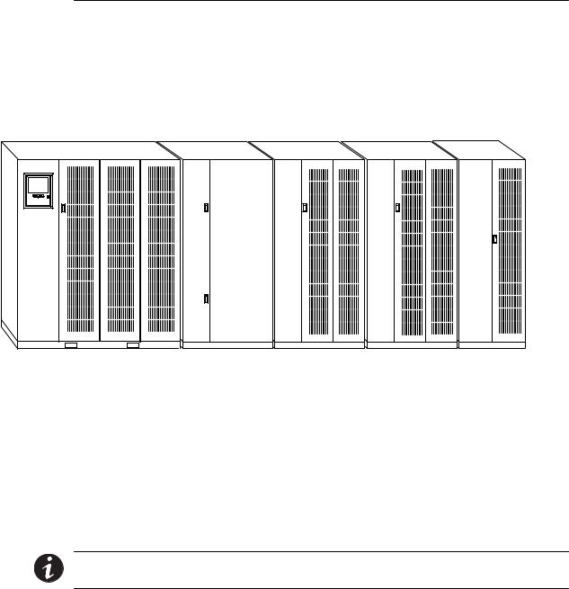
Each component of the UPS system is housed in a free-standing cabinet designed for industrial or computer room applications. The cabinets match in style and color, and have safety shields behind the doors for hazardous voltage protection. Figure 2-1 shows a typical Powerware 9315 UPS system.
UPS |
Battery |
Input |
Output |
PDM |
Cabinet |
Cabinet |
Transformer |
Transformer |
Cabinet |
|
(optional) |
Cabinet |
Cabinet |
(optional– |
|
|
|
(optional) |
requires 480/208 |
|
|
|
|
transformer) |
Figure 2-1. Typical Powerware 9315 UPS System
Each cabinet of the UPS system is shipped separately. As shown in Figure 2-1, you can combine a UPS with any of the options described in this manual to meet your system needs. The UPS and options are described in detail later in this manual. The following descriptions provide a brief overview of standard UPS features and available enhancements.
NOTE You should read this manual and have thorough knowledge of UPS operation before attempting to operate any of the UPS switches, controls, or optional components.
2-2 |
EATON Powerware® 9315 UPS (200–300 kVA) Operation Manual S 164201036 Rev F powerware.com |
Getting Started
2.3 Looking Inside the UPS
The Powerware 9315 is a continuous-duty, solid-state UPS that supports the following equipment: process control, data processing, telecommunications/PBX, research, and medical. The Powerware 9315 maintains power to the critical loads during commercial electrical power brownout, blackout, overvoltage, undervoltage, and out-of-tolerance frequency conditions.
The power required by your equipment is called the critical load. The UPS supplies the critical load with conditioned power that is synchronized with your utility power. Figure 2-2 shows the main elements of the UPS.
Battery Cabinet 
|
Power Processing |
|
|
|
Unit (PPU) |
Output |
|
AC Input to |
|
Transformer |
AC Output |
|
|
||
Rectifier/ |
|
|
to Critical |
Charger |
|
Output |
Load |
Rectifier/ |
Inverter |
Contactor |
|
Charger |
|
|
|
Input |
Digital |
|
|
Filter |
|
|
|
|
Metering |
|
|
AC Input to |
Static |
Bypass |
Switch |
Bypass
Contactor
UPS Cabinet
Figure 2-2. Main Elements of the UPS System
If utility power is interrupted or falls outside the parameters specified in Chapter 9, “Product Specifications,” the UPS uses a backup battery supply to maintain power to the critical load for a specified period of time or until the utility power returns. For extended power outages, the backup battery supply allows you to either transfer to an alternative power system (such as a generator) or shut down the critical load in an orderly manner.
The operation of the UPS system is described in greater detail in Chapter 3, “Understanding UPS Operation.” Chapter 9, “Product Specifications,” outlines the storage and operating specifications for the UPS and optional battery.
EATON Powerware® 9315 UPS (200–300 kVA) Operation Manual S 164201036 Rev F powerware.com |
2-3 |
Getting Started
2.4 UPS Standard Features
The UPS has many standard features that provide cost-effective and consistently reliable power protection:
2.4.1 Monitor Panel
The Monitor Panel on the front of the UPS contains an LCD screen to display the current status of the UPS. You can view a statistical history and log of UPS events and display a real-time graphic representation of power flowing through the UPS components. Backlit status indicators show the operating mode of the UPS and alert you to system events. The emergency LOAD OFF button is also located on the monitor panel and is described in Chapter 5, “Using the Monitor Panel.”
2.4.2 Control Panel
The Control Panel inside the right door of the UPS contains the operator controls to start and stop the UPS, change the operating mode, and reset the LOAD OFF button. The Control Panel is described in “Using the Control Panel” on page 4-1.
2.4.3Communication Bays
X-Slot® Communication Bay – The Communications Bay allows internal, UPS-powered communication with optional X-Slot cards. The X-Slot cards support several protocols such as SNMP, HTTP, and Modbus®. See Chapter 7, “Communication” for additional information.
Computer Interface – Serial communication ports are standard on all UPSs, and are electrically isolated from the UPS. You can use these ports to link the UPS to the features described in Chapter 7, “Communication.”
Summary Alarm Contacts – Alarm contacts are provided for connection to equipment at your facility such as a light, an audible alarm, or a computer terminal. The equipment you connect to these contacts alerts you to a UPS alarm. This feature is described further in Chapter 6, “Using Features and Options.”
Building Alarm Monitoring – You can connect your facility’s alarm system contacts to six inputs in the UPS. The UPS uses these inputs to monitor your building alarms in addition to the UPS status. This feature is described further in Chapter 6, “Using Features and Options.”
2.4.4Input Filter
Your UPS may be equipped with an input filter. An input filter yields power factor correction that allows you to save on the initial installation and operating costs. The filter also reduces input harmonic current distortion and minimizes upstream interference that can damage sensitive hardware components.
2-4 |
EATON Powerware® 9315 UPS (200–300 kVA) Operation Manual S 164201036 Rev F powerware.com |
Getting Started
2.4.5 Emergency Load Off
A LOAD OFF button is provided for situations where you must immediately remove all power to the critical load. The button is located on the front of the UPS for quick access and is covered with a clear plastic shield to prevent inadvertent operation. The shield must be raised before pressing the button. The LOAD OFF button is described in detail in Chapter 11, “Using the LOAD OFF Button.”
2.4.6 Automatic Battery Charge Current Limit
A preset limit restricts battery charging current to protect batteries from damage due to high current charging. Charging at high currents can overheat and damage batteries.
2.4.7 Installation Features
Power wiring can be routed through the top or bottom of each UPS cabinet. External sensing and monitoring control wire must be installed in accordance with Class 2 wiring methods. Bottom entry is provided for Class 2 wiring.
2.5 Options and Accessories
Contact a Powerware sales representative for information about any of these available options:
2.5.1 Battery
You can enhance the protection provided by the UPS with one or more backup battery supplies equipped with sealed lead-acid, maintenance-free batteries in a matching cabinet. Each battery cabinet contains individual modular battery trays and a battery circuit breaker. Several battery capacities are available.
The UPS battery cabinets can be paralleled; you can increase the battery backup time by adding battery cabinets to your UPS system. The Powerware 9315 can support up to four battery cabinets.
2.5.2 External Battery Disconnect
An optional DC circuit breaker, enclosed in a wall-mounted box adjacent to the UPS, provides a manual means of disconnecting a battery that is located remotely from the UPS. This option is described further in Chapter 6, “Using Features and Options.”
EATON Powerware® 9315 UPS (200–300 kVA) Operation Manual S 164201036 Rev F powerware.com |
2-5 |
Getting Started
2.5.3 Power Distribution Module (LV models only)
An optional output Power Distribution Module (PDM) is available to distribute the output power of the UPS to the critical load. The PDM cabinet has one or two panels, each containing up to 42 poles for breaker switches. This arrangement provides flexibility for the needs of your facility. Each panel is controlled by one 225A feeder breaker. The PDM is enclosed in a separate cabinet that matches the UPS. This option requires a 480 to 208V transformer.
2.5.4 Upgrade Capability
The UPS is available in various output power ratings in both 50 and 60 Hz models. If your power requirements increase, you can upgrade the UPS system to provide more output power with minimum impact on your facility.
2.5.5 Remote Monitor Panel
An optional Remote Monitor Panel (RMP) contains backlit status indicators and a local horn, allowing you to monitor the operational status and alarm condition of the UPS from virtually any location within your facility. You can install multiple RMPs at remote locations to increase your monitoring capabilities. This option is described further in Chapter 6, “Using Features and Options.”
2.5.6 Relay Interface Module
An optional Relay Interface Module (RIM) uses relay contact closures to indicate the operating status and alarm condition of the UPS system. The module uses a serial interface line and may support up to eight critical loads. This option is described further in
Chapter 6, “Using Features and Options.”
2.5.7 Input Isolation Transformer
Optional 480/480, 208/480, or 600/480 Vac input isolation transformers provide an isolated input to the rectifier for applications that require a DC link that is not ground referenced or for applications requiring an input of 208 or 600 Vac. The transformers are contained in separate cabinets.
2.5.8 5% Input Filter
An optional 480/480 Vac 5% input filter reduces input harmonic current distortion and minimizes upstream interference that can damage sensitive hardware components. The filter is contained in a separate cabinet.
2-6 |
EATON Powerware® 9315 UPS (200–300 kVA) Operation Manual S 164201036 Rev F powerware.com |
Getting Started
2.5.9 Output Transformer
An optional 480/208 Vac output auto transformer provides a 208 Vac output for applications that require 208 Vac. The transformer is contained in a separate cabinet.
2.5.10 Modem
An optional modem is available for use with the UPS Remote Notification feature described in “Remote Notification” on page 7-19. Refer to the manual supplied with the modem for operating instructions.
2.5.11 Customer Convenience Outlet
An uninterruptible 120 Vac, 0.2A, fuse-protected convenience outlet is provided to supply power to the optional modem. It is located adjacent to the Communication Panel.
EATON Powerware® 9315 UPS (200–300 kVA) Operation Manual S 164201036 Rev F powerware.com |
2-7 |

Getting Started
2.6 Symbols, Controls, and Indicators
These symbols may appear on the UPS system or on labels inside the UPS. They are accepted by most international safety agents. Everyone in your organization who works with your UPS should understand the meaning of these symbols:
ON - The principal power switch is in the On position.
OFF - The principal power switch is in the Off position.
PHASE - The word “phase.”
RISK OF ELECTRIC SHOCK - Indicates that a risk of electric shock is present and the associated warning should be observed.
CAUTION: REFER TO OPERATOR’S MANUAL - Refer to your operator’s manual for additional information, such as important operating and maintenance instructions.
This symbol indicates that you should not discard the UPS or the UPS batteries in the trash. The UPS may contain sealed, lead-acid batteries. Batteries must be recycled.
This symbol indicates that you should not discard waste electrical or electronic equipment (WEEE) in the trash. For proper disposal, contact your local recycling/reuse or hazardous waste center.
2-8 |
EATON Powerware® 9315 UPS (200–300 kVA) Operation Manual S 164201036 Rev F powerware.com |

Chapter 3 Understanding UPS Operation
The UPS functions automatically to supply AC electrical power to the critical load. The UPS always operates in one of three modes:
In Normal mode, the critical load is supplied by the inverter, which derives its power from rectified utility AC power. In this mode, the rectifier also provides charging current for the battery.
In Bypass mode, the critical load is directly supported by utility power.
In Battery mode, the battery cabinet provides DC power, which maintains inverter operation. The battery supports the critical load.
The UPS continually monitors itself and the incoming utility power, and automatically switches between these modes as required, with no operator intervention. The sophisticated detection and switching logic inside the UPS ensures that operating mode changes are automatic and transparent to the critical load. The UPS switches operating modes in response to these system events:
A command is an intervention that is externally initiated by an operator or by some site action. A command causes the UPS to switch operating modes; it usually does not require any further action by you.
A notice is a minor system event that may or may not require your attention.
An alarm is a system event that requires immediate operator intervention.
System events, alarm horns, and indicator lights are described in Chapter 10, “Responding to System Events.”
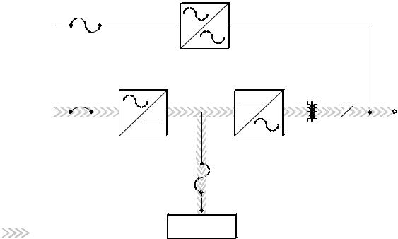
3.1 Normal Mode
In Normal mode, utility AC power is supplied to the rectifier. The rectifier supplies DC power to the inverter, which then supplies the critical load with AC power. The rectifier also provides charging power to the battery. The battery charge condition is monitored by the UPS and reported by a status indicator on the Monitor Panel. The message “System Normal” appears in the status area of the LCD screen.
Figure 3-1 shows the path of electrical power through the UPS system when the UPS is operating in Normal mode.
EATON Powerware® 9315 UPS (200–300 kVA) Operation Manual S 164201036 Rev F powerware.com |
3-1 |
Understanding UPS Operation
Bypass
Bypass
Input
K4
|
Rectifier |
Inverter |
Rectifier |
CB1 |
|
|
|
|
Input |
|
|
K3 Output
(Closed) |
Transformer |
Path of electrical power |
Battery |
|
Figure 3-1. Path of Current Through the UPS in Normal Mode
If the utility AC power is interrupted or is out of specification, the UPS automatically switches to Battery mode to support the critical load with no interruption. When utility power returns, the UPS returns to Normal mode.
If the UPS system becomes overloaded, the UPS switches to Bypass mode. The UPS automatically returns to Normal mode when the error condition is cleared and system operation is restored within specified limits.
If the UPS suffers an internal failure, it switches automatically to Bypass mode and remains in that mode until the failure is corrected and the UPS is back in service.
3-2 |
EATON Powerware® 9315 UPS (200–300 kVA) Operation Manual S 164201036 Rev F powerware.com |
Understanding UPS Operation
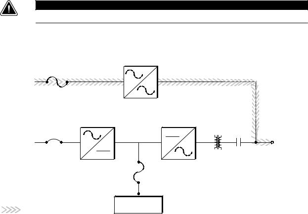
3.2 Bypass Mode
The UPS automatically switches to Bypass mode if it detects an overload, load fault, or internal failure. The bypass source supplies the commercial AC power to the load directly.
C A U T I O N
The critical load is not protected while the UPS is in Bypass mode.
Figure 3-2 shows the path of electrical power through the UPS system when the UPS is operating in Bypass mode.
|
|
Bypass |
|
|
Bypass |
|
|
|
|
Input |
|
|
|
|
|
|
K4 |
|
|
|
Rectifier |
Inverter |
Output |
|
Rectifier |
CB1 |
K3 |
||
|
||||
|
|
|
||
Input |
|
(Open) |
|
|
|
|
|
||
|
|
Transformer |
|
Path of electrical power |
Battery |
|
Figure 3-2. Path of Current Through the UPS in Bypass Mode
You can transfer the UPS from Normal mode to Bypass mode manually. However, the UPS switches automatically to Bypass mode whenever the inverter can no longer supply the critical load. If the UPS transfers to Bypass mode from Normal mode due to any reason other than operator intervention, the UPS automatically attempts to transfer back to Normal mode (up to three times within a 10-minute period). The fourth transfer will lock the critical load on the bypass source and requires operator intervention to transfer.
Bypass mode is a normal operating mode, and not an alarm condition. However, if the UPS is unable to return to Normal mode following an automatic transfer to Bypass mode, an alarm condition is recorded.
EATON Powerware® 9315 UPS (200–300 kVA) Operation Manual S 164201036 Rev F powerware.com |
3-3 |
Understanding UPS Operation
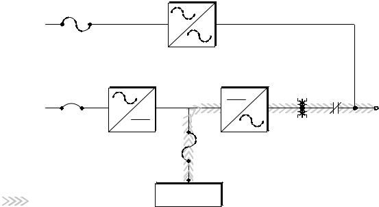
3.3 Battery Mode
The UPS transfers to Battery mode automatically if a utility power outage occurs, or if the utility power does not conform to specified parameters. In Battery mode, the battery provides emergency DC power that the inverter converts to AC power. When the UPS switches to Battery mode, the alarm indications depend on the cause and condition of the battery charge. The length of time the system can operate in Battery mode depends on load configuration and the battery charge.
Figure 3-3 shows the path of electrical power through the UPS when operating in Battery mode.
Bypass
Bypass
Input
K4
|
Rectifier |
Inverter |
Rectifier |
CB1 |
|
|
|
|
Input |
|
|
K3 |
Output |
|
|
(Closed) |
|
Transformer |
|
Path of electrical power |
Battery |
|
Figure 3-3. Path of Current Through the UPS in Battery Mode
When the discharging battery voltage reaches the lower limit of UPS operation capability, the critical load transfers to Bypass mode if it is available. If Bypass input is not available, a “Shutdown Imminent” warning occurs. The warning time before critical load loss occurs is approximately two minutes, depending on load configuration and the battery charge.
If incoming power returns to within specified parameters, the UPS automatically returns to Normal mode and alarm indications clear. However, the process of returning to Normal mode is not instantaneous. The rectifier gradually draws increasing power from the incoming utility until Normal mode is achieved.
3-4 |
EATON Powerware® 9315 UPS (200–300 kVA) Operation Manual S 164201036 Rev F powerware.com |

Understanding UPS Operation
3.4 Monitoring and Controlling UPS Operation
After you start the UPS, no operator intervention is necessary except for periodic checks of the UPS status. Manual operation is required only during routine maintenance or service. Use the Monitor Panel and the Control Panel to monitor and control the UPS. Figure 3-4 shows the location of these two panels on the front of the UPS.
Control Panel
Monitor
Panel
Figure 3-4. Location of the Monitor Panel and the Control Panel
The Monitor Panel on the left front of the UPS continually indicates the present mode of UPS operation. This panel contains an LCD screen, backlit status indicators, and the LOAD OFF button. Use the LCD screen on the Monitor Panel to view performance meters or graphic representations of UPS operation. The Monitor Panel is described in detail in Chapter 5, “Using the Monitor Panel.” A quick reference label describing how to use the Monitor Panel is located inside the UPS above the Control Panel.
Open the right front door of the UPS to view the Control Panel containing various controls and switches. These control power to and from the UPS, and allow you to change the UPS mode manually. The Control Panel is discussed in “Using the Control Panel” on page 4-1.
EATON Powerware® 9315 UPS (200–300 kVA) Operation Manual S 164201036 Rev F powerware.com |
3-5 |
Understanding UPS Operation
This page intentionally left blank.
3-6 |
EATON Powerware® 9315 UPS (200–300 kVA) Operation Manual S 164201036 Rev F powerware.com |
Chapter 4 Starting and Stopping the UPS
This chapter describes how to use the Control Panel to start and stop the UPS.
NOTE Before starting the UPS, ensure all installation tasks are complete and a preliminary startup has been performed by authorized service personnel. The preliminary startup verifies all electrical interconnections to ensure the installation was successful and the UPS system operates properly.
4.1 Using the Control Panel
The Control Panel is inside the right-hand door of the UPS cabinet (see Figure 4-1). Although the Control Panel appears easy to use, you should read these instructions and thoroughly understand how the controls work before attempting to use them.
C A U T I O N
Incorrect use of the power controls on the Control Panel can cause a loss of power to the protected equipment.
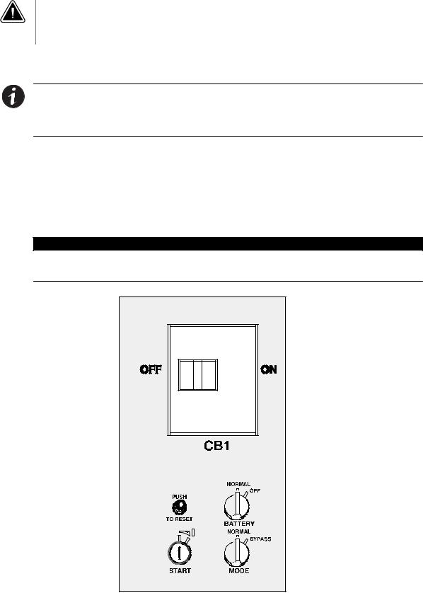
Figure 4-1. UPS Control Panel
EATON Powerware® 9315 UPS (200–300 kVA) Operation Manual S 164201036 Rev F powerware.com |
4-1 |
Starting and Stopping the UPS
The following describes the switches on the Control Panel (see Figure 4-1):
The MODE switch is a two-position rotary switch that controls the manual transfer of the UPS to and from Bypass mode. The MODE switch is used to:
-Place the critical load in Bypass mode when the UPS is operating in Normal mode and the bypass source is within acceptable limits. If the transfer does not occur within two seconds, an alarm sounds.
-Prevent transfer to Normal mode when the UPS is in Bypass mode.
-Shut down the power processing unit (inverter and rectifier) of the UPS.
The BATTERY switch is a two-position rotary switch that allows you to manually shunt trip the battery breakers in remote cabinets.
The circuit breaker (CB1) switch controls the operation of the rectifier and inverter. If CB1 is on (closed), the rectifier turns on when the START switch is activated and the proper voltage is at the input terminals.
The PUSH TO RESET button is described in “Resetting the UPS System after Load Off” on page 11-2.
The START switch activates the power controls on the Control Panel. The START switch is center-biased (the key will rest only in the upright position). Its operation is similar to that of an automobile ignition switch. After setting the operator controls, you turn the START switch to the right momentarily to activate the controls. When you release it, it returns to the upright position.
The following sections describe how to operate these controls to start, stop, or change the operating mode of the UPS.
4.1.1To Place the UPS in Normal Mode
1.Close the Input Power Feeder breaker.
2.Verify that the Load Off PUSH TO RESET button is pressed in.
3.Turn the BATTERY switch to NORMAL.
4.Turn the MODE switch to NORMAL.
5.Move the CB1 switch to ON.
6.Turn the START switch to the right momentarily.
The rectifier turns on, then the inverter turns on. The UPS display and alarm alert you to close the battery breaker.
7.Close the battery breaker(s).
4-2 |
EATON Powerware® 9315 UPS (200–300 kVA) Operation Manual S 164201036 Rev F powerware.com |
Starting and Stopping the UPS
When the inverter reaches full voltage, it turns on and supplies power to the critical load. It takes less than one minute for the UPS to achieve Normal mode.
If a bypass source is available when you turn the START switch on, the critical load is immediately supplied by the bypass source in Bypass mode until the inverter turns on and the UPS transfers to Normal mode. The status indicators on the Monitor Panel indicate when the UPS is in Bypass mode or Normal mode as appropriate.
4.1.2To Shut Down the UPS from Normal Mode
1.Turn the MODE switch to BYPASS.
The UPS switches to Bypass mode. If the bypass source is not available, the power processor remains on and an alarm sounds.
2.When the transfer is complete (the LCD screen reads “On Bypass”), move the CB1 switch to OFF.
The bypass source supplies the critical load and the power processor de-energizes. The Bypass mode indicator illuminates on the Monitor Panel.
4.1.3To Start the UPS in Bypass Mode
If the PPU of the UPS is not available and you need to energize the critical load right away, you can energize the critical load without the benefit of backup. To turn the UPS on in Bypass mode:
1.Turn the MODE switch to BYPASS. (The remaining switches can be in any position.)
2.Turn the START switch to the right momentarily.
Power to the critical load is supplied by the bypass source. No backup is available.
4.1.4To Shut Down Power to the Critical Load While in Bypass Mode
To perform maintenance or service on the critical load, you must shut it down first:
1.Turn off all equipment that is being powered through the UPS.
2.Press the LOAD OFF button on the Monitor Panel.
EATON Powerware® 9315 UPS (200–300 kVA) Operation Manual S 164201036 Rev F powerware.com |
4-3 |
Starting and Stopping the UPS
This page intentionally left blank.
4-4 |
EATON Powerware® 9315 UPS (200–300 kVA) Operation Manual S 164201036 Rev F powerware.com |
Loading...