


 Loading...
Powerware Series
Eaton® 9170+ UPS 3–18 kVA
User's Guide
Requesting a Declaration of Conformity
Units that are labeled with a CE mark comply with the following harmonized standards and EU directives:
SHarmonized Standards: EN 50091-1-1 and EN 50091-2; IEC 60950 Third Edition
S EU Directives: |
73/23/EEC, Council Directive on equipment designed for use within certain voltage limits |
|
93/68/EEC, Amending Directive 73/23/EEC |
|
89/336/EEC, Council Directive relating to electromagnetic compatibility |
|
92/31/EEC, Amending Directive 89/336/EEC relating to EMC |
The EC Declaration of Conformity is available upon request for products with a CE mark. For copies of the EC Declaration of Conformity, contact:
Eaton Corporation
Koskelontie 13
FIN-02920 Espoo
Finland
Phone: +358-9-452 661
Fax: +358-9-452 665 68
Eaton, Powerware, and FERRUPS are registered trademarks and ConnectUPS and BestDock are trademarks of Eaton Corporation or its subsidiaries and affiliates. Torx is a registered trademark of Textron, Inc. All other trademarks are property of their respective companies.
ECopyright 2000–2010 Eaton Corporation, Raleigh, NC, USA. All rights reserved. No part of this document may be reproduced in any way without the express written approval of Eaton Corporation.
Class A EMC Statements
FCC Part 15
NOTE This equipment has been tested and found to comply with the limits for a Class A digital device, pursuant to part 15 of the FCC Rules. These limits are designed to provide reasonable protection against harmful interference when the equipment is operated in a commercial environment. This equipment generates, uses, and can radiate radio frequency energy and, if not installed and used in accordance with the instruction manual, may cause harmful interference to radio communications. Operation of this equipment in a residential area is likely to cause harmful interference in which case the user will be required to correct the interference at his own expense.
ICES-003
This Class A Interference Causing Equipment meets all requirements of the Canadian Interference Causing Equipment Regulations ICES 003.
Cet appareil numérique de la classe A respecte toutes les exigences du Reglement sur le matériel brouilleur du Canada.
EN 50091-2
Some configurations are classified under EN 50091 2 as “Class A UPS for Unrestricted Sales Distribution.” For these configurations, the following applies:
WARNING This is a Class A UPS Product. In a domestic environment, this product may cause radio interference, in which case, the user may be required to take additional measures.
VCCI Notice

Special Symbols
The following are examples of symbols used on the UPS or accessories to alert you to important information:
RISK OF ELECTRIC SHOCK - Indicates that a risk of electric shock is present and the associated warning should be observed.
CAUTION: REFER TO OPERATOR'S MANUAL - Refer to your operator's manual for additional information, such as important operating and maintenance instructions.
This symbol indicates that you should not discard the UPS or the UPS batteries in the trash. This product contains sealed, lead acid batteries and must be disposed of properly. For more information, contact your local recycling/reuse or hazardous waste center.
This symbol indicates that you should not discard waste electrical or electronic equipment (WEEE) in the trash. For proper disposal, contact your local recycling/reuse or hazardous waste center.
Table of Contents
1 |
Introduction . . . . . . . . . . . . . . . . . . . . . . . . . . . . . . . . . . . . . . . . . . . . . . . . . . . . . . . . |
1 |
|
Safety Warnings . . . . . . . . . . . . . . . . . . . . . . . . . . . . . . . . . . . . . . . . . . . . . . . . . . . . . . . . . . . . . . . . . . . . |
2 |
|
Physical Features . . . . . . . . . . . . . . . . . . . . . . . . . . . . . . . . . . . . . . . . . . . . . . . . . . . . . . . . . . . . . . . . . . . . |
5 |
2 |
Installation Setup . . . . . . . . . . . . . . . . . . . . . . . . . . . . . . . . . . . . . . . . . . . . . . . . . . . |
9 |
|
Equipment Clearances . . . . . . . . . . . . . . . . . . . . . . . . . . . . . . . . . . . . . . . . . . . . . . . . . . . . . . . . . . . . . . . . |
9 |
|
Location Requirements . . . . . . . . . . . . . . . . . . . . . . . . . . . . . . . . . . . . . . . . . . . . . . . . . . . . . . . . . . . . . . . . |
10 |
|
UPS Setup . . . . . . . . . . . . . . . . . . . . . . . . . . . . . . . . . . . . . . . . . . . . . . . . . . . . . . . . . . . . . . . . . . . . . . . . |
10 |
|
Threeand Six-Slot Cabinets . . . . . . . . . . . . . . . . . . . . . . . . . . . . . . . . . . . . . . . . . . . . . . . . . . . . . . . . . |
10 |
|
Nineand Twelve-Slot Cabinets . . . . . . . . . . . . . . . . . . . . . . . . . . . . . . . . . . . . . . . . . . . . . . . . . . . . . . . |
11 |
|
Caster Cart Installation (Threeand Six-Slot Cabinets) . . . . . . . . . . . . . . . . . . . . . . . . . . . . . . . . . . . . . . . . . . |
12 |
|
Stabilizer Bracket Installation (Twelve-Slot Cabinet Only) . . . . . . . . . . . . . . . . . . . . . . . . . . . . . . . . . . . . . . . |
13 |
|
Rack-Mount Installation (Threeand Six-Slot Cabinets) . . . . . . . . . . . . . . . . . . . . . . . . . . . . . . . . . . . . . . . . . |
14 |
|
Floor Anchor Kit Installation . . . . . . . . . . . . . . . . . . . . . . . . . . . . . . . . . . . . . . . . . . . . . . . . . . . . . . . . . . . . |
16 |
|
Moving the Cabinets . . . . . . . . . . . . . . . . . . . . . . . . . . . . . . . . . . . . . . . . . . . . . . . . . . . . . . . . . . . . . . . . . |
17 |
3 |
UPS with Bypass Electrical Installation . . . . . . . . . . . . . . . . . . . . . . . . . . . . . . . . . . |
19 |
|
Input Current Ratings . . . . . . . . . . . . . . . . . . . . . . . . . . . . . . . . . . . . . . . . . . . . . . . . . . . . . . . . . . . . . . . . . |
21 |
|
Bypass Switches . . . . . . . . . . . . . . . . . . . . . . . . . . . . . . . . . . . . . . . . . . . . . . . . . . . . . . . . . . . . . . . . . . . . |
22 |
|
Bypass Switch Operation . . . . . . . . . . . . . . . . . . . . . . . . . . . . . . . . . . . . . . . . . . . . . . . . . . . . . . . . . . . |
23 |
|
UPS Installation with an External Bypass Switch . . . . . . . . . . . . . . . . . . . . . . . . . . . . . . . . . . . . . . . . . . . . . |
26 |
|
System Wiring Diagrams . . . . . . . . . . . . . . . . . . . . . . . . . . . . . . . . . . . . . . . . . . . . . . . . . . . . . . . . . . . . . . |
34 |
4 |
UPS Electrical Installation . . . . . . . . . . . . . . . . . . . . . . . . . . . . . . . . . . . . . . . . . . . . |
39 |
|
Input Current Ratings . . . . . . . . . . . . . . . . . . . . . . . . . . . . . . . . . . . . . . . . . . . . . . . . . . . . . . . . . . . . . . . . . |
40 |
|
UPS Electrical Installation . . . . . . . . . . . . . . . . . . . . . . . . . . . . . . . . . . . . . . . . . . . . . . . . . . . . . . . . . . . . . |
42 |
|
System Wiring Diagrams . . . . . . . . . . . . . . . . . . . . . . . . . . . . . . . . . . . . . . . . . . . . . . . . . . . . . . . . . . . . . . |
48 |
5 |
Isolated Output Wiring Diagrams . . . . . . . . . . . . . . . . . . . . . . . . . . . . . . . . . . . . . . . |
53 |
|
Neutral-to-Ground Bonding for Isolated Output . . . . . . . . . . . . . . . . . . . . . . . . . . . . . . . . . . . . . . . . . . . . . . . |
54 |
|
System Wiring Diagrams . . . . . . . . . . . . . . . . . . . . . . . . . . . . . . . . . . . . . . . . . . . . . . . . . . . . . . . . . . . . . . |
56 |
6 |
Battery Cabinet Installation . . . . . . . . . . . . . . . . . . . . . . . . . . . . . . . . . . . . . . . . . . . |
61 |
7 |
UPS Startup . . . . . . . . . . . . . . . . . . . . . . . . . . . . . . . . . . . . . . . . . . . . . . . . . . . . . . . . |
67 |
|
Power and Battery Module Installation . . . . . . . . . . . . . . . . . . . . . . . . . . . . . . . . . . . . . . . . . . . . . . . . . . . . |
67 |
|
Startup for Plug-Receptacle Units . . . . . . . . . . . . . . . . . . . . . . . . . . . . . . . . . . . . . . . . . . . . . . . . . . . . . . . . |
69 |
Eaton 9170+ UPS (3–18 kVA) User's Guide S 164201393 Rev E www.eaton.com/powerquality |
i |
TABLE OF CONTENTS
|
Startup for Hardwired Units . . . . . . . . . . . . . . . . . . . . . . . . . . . . . . . . . . . . . . . . . . . . . . . . . . . . . . . . . . . . |
71 |
|
Initial Startup Parameters . . . . . . . . . . . . . . . . . . . . . . . . . . . . . . . . . . . . . . . . . . . . . . . . . . . . . . . . . . . . . . |
74 |
8 |
Operation . . . . . . . . . . . . . . . . . . . . . . . . . . . . . . . . . . . . . . . . . . . . . . . . . . . . . . . . . . |
77 |
|
Turning the UPS On . . . . . . . . . . . . . . . . . . . . . . . . . . . . . . . . . . . . . . . . . . . . . . . . . . . . . . . . . . . . . . . . . . |
79 |
|
Removing Input Power . . . . . . . . . . . . . . . . . . . . . . . . . . . . . . . . . . . . . . . . . . . . . . . . . . . . . . . . . . . . . . . . |
79 |
|
Front Panel Display . . . . . . . . . . . . . . . . . . . . . . . . . . . . . . . . . . . . . . . . . . . . . . . . . . . . . . . . . . . . . . . . . . |
80 |
|
Using the Front Panel Display . . . . . . . . . . . . . . . . . . . . . . . . . . . . . . . . . . . . . . . . . . . . . . . . . . . . . . . . . . . |
81 |
|
Parameters . . . . . . . . . . . . . . . . . . . . . . . . . . . . . . . . . . . . . . . . . . . . . . . . . . . . . . . . . . . . . . . . . . . . . . . . |
83 |
|
Changing Parameter Settings . . . . . . . . . . . . . . . . . . . . . . . . . . . . . . . . . . . . . . . . . . . . . . . . . . . . . . . . . . . |
83 |
|
Reading the Eaton 9170+ System Logs . . . . . . . . . . . . . . . . . . . . . . . . . . . . . . . . . . . . . . . . . . . . . . . . . . . . |
84 |
|
Inverter Log . . . . . . . . . . . . . . . . . . . . . . . . . . . . . . . . . . . . . . . . . . . . . . . . . . . . . . . . . . . . . . . . . . . . . |
84 |
|
Alarm Log . . . . . . . . . . . . . . . . . . . . . . . . . . . . . . . . . . . . . . . . . . . . . . . . . . . . . . . . . . . . . . . . . . . . . . |
85 |
|
Battery Test . . . . . . . . . . . . . . . . . . . . . . . . . . . . . . . . . . . . . . . . . . . . . . . . . . . . . . . . . . . . . . . . . . . . . . . |
86 |
|
Menu Map . . . . . . . . . . . . . . . . . . . . . . . . . . . . . . . . . . . . . . . . . . . . . . . . . . . . . . . . . . . . . . . . . . . . . . . . |
87 |
9 |
Communication . . . . . . . . . . . . . . . . . . . . . . . . . . . . . . . . . . . . . . . . . . . . . . . . . . . . . |
89 |
|
Power Management and Protection Software . . . . . . . . . . . . . . . . . . . . . . . . . . . . . . . . . . . . . . . . . . . . . . . . |
89 |
|
Optional Interface Kits . . . . . . . . . . . . . . . . . . . . . . . . . . . . . . . . . . . . . . . . . . . . . . . . . . . . . . . . . . . . . . . . |
89 |
|
Communication Slots . . . . . . . . . . . . . . . . . . . . . . . . . . . . . . . . . . . . . . . . . . . . . . . . . . . . . . . . . . . . . . . . . |
89 |
|
ConnectUPSt Web/SNMP Card (BD Model) . . . . . . . . . . . . . . . . . . . . . . . . . . . . . . . . . . . . . . . . . . . . . . . |
90 |
|
Relay Interface Card (BestDock Model) . . . . . . . . . . . . . . . . . . . . . . . . . . . . . . . . . . . . . . . . . . . . . . . . . . |
90 |
|
Dedicated Input Signals . . . . . . . . . . . . . . . . . . . . . . . . . . . . . . . . . . . . . . . . . . . . . . . . . . . . . . . . . . . . . . . |
90 |
|
DB-9 Communication Port . . . . . . . . . . . . . . . . . . . . . . . . . . . . . . . . . . . . . . . . . . . . . . . . . . . . . . . . . . . . . . |
92 |
10 |
Maintenance . . . . . . . . . . . . . . . . . . . . . . . . . . . . . . . . . . . . . . . . . . . . . . . . . . . . . . . |
93 |
|
Routine Maintenance . . . . . . . . . . . . . . . . . . . . . . . . . . . . . . . . . . . . . . . . . . . . . . . . . . . . . . . . . . . . . . . . . |
93 |
|
Storage Temperature . . . . . . . . . . . . . . . . . . . . . . . . . . . . . . . . . . . . . . . . . . . . . . . . . . . . . . . . . . . . . . . . . |
94 |
|
External Bypass Switch (Make-Before-Break Only) Operation . . . . . . . . . . . . . . . . . . . . . . . . . . . . . . . . . . . . . |
94 |
|
Battery Replacement . . . . . . . . . . . . . . . . . . . . . . . . . . . . . . . . . . . . . . . . . . . . . . . . . . . . . . . . . . . . . . . . . |
94 |
|
Power Module Replacement . . . . . . . . . . . . . . . . . . . . . . . . . . . . . . . . . . . . . . . . . . . . . . . . . . . . . . . . . . . . |
95 |
11 |
Specifications . . . . . . . . . . . . . . . . . . . . . . . . . . . . . . . . . . . . . . . . . . . . . . . . . . . . . . |
97 |
12 |
Troubleshooting . . . . . . . . . . . . . . . . . . . . . . . . . . . . . . . . . . . . . . . . . . . . . . . . . . . . . |
107 |
|
Alarms . . . . . . . . . . . . . . . . . . . . . . . . . . . . . . . . . . . . . . . . . . . . . . . . . . . . . . . . . . . . . . . . . . . . . . . . . . . |
109 |
|
Service and Support . . . . . . . . . . . . . . . . . . . . . . . . . . . . . . . . . . . . . . . . . . . . . . . . . . . . . . . . . . . . . . . . . . |
113 |
13 |
Warranty . . . . . . . . . . . . . . . . . . . . . . . . . . . . . . . . . . . . . . . . . . . . . . . . . . . . . . . . . . |
115 |
|
Two-Year Limited Warranty (US and Canada) . . . . . . . . . . . . . . . . . . . . . . . . . . . . . . . . . . . . . . . . . . . . . . . . |
115 |
|
Load Protection Guarantee (US and Canada) . . . . . . . . . . . . . . . . . . . . . . . . . . . . . . . . . . . . . . . . . . . . . . . . . |
117 |
ii |
Eaton 9170+ UPS (3–18 kVA) User's Guide S 164201393 Rev E www.eaton.com/powerquality |
Chapter 1 |
Introduction |
The Eaton® 9170+ uninterruptible power system (UPS) is a modular UPS that contains battery modules and power control modules (referred to as power modules). These modules plug into a rack cabinet structure containing additional control, communication, and display functions that enable integrated control of all power modules. The UPS is housed in a single cabinet, with extra battery capacity housed in auxiliary battery cabinets.
The pluggable power modules can be removed and replaced (hot-swapped) without powering the UPS down if the UPS has sufficient redundant capacity. Battery modules may also be hot-swapped for maintenance. Power control circuitry in the cabinet senses problems in power modules, and automatically transfers control and load to the remaining power modules.
All power modules share the load requirements equally. For example, three power modules are capable of supplying a total of 9 kVA. If a load requires only 4.5 kVA, each power module supplies 1.5 kVA to the output. If one power module is removed or for some reason fails, each of the two remaining power modules would supply half of the load, or 2.25 kVA. In other words, redundancy exists when the load can be supplied by less than all of the installed power modules.
The UPS can be configured with up to seven power and/or optional battery charger modules; its output is limited such that an excess number of power modules allow the failure of one or more modules without causing the UPS to lose any functionality.
To permit UPS removal from the power path while maintaining power to the loads, an external bypass switch is required. This switch is optional but recommended for system serviceability.
Eaton 9170+ UPS (3–18 kVA) User's Guide S 164201393 Rev E www.eaton.com/powerquality |
1 |
INTRODUCTION
Safety Warnings
IMPORTANT SAFETY INSTRUCTIONS
SAVE THESE INSTRUCTIONS
This manual contains important instructions that you should follow during installation and maintenance of the UPS and batteries. Please read all instructions before operating the equipment and save this manual for future reference.
C A U T I O N
SSplit-phase power modules (model ASY-0673) have brown labels on the front and produce two output voltages: 100/100 for 200, 110/110 for 220, 120/120 for 240, 120/120 for 208, or 127/127 for 220 Vac. Universal power modules (model ASY-0674) have black labels on the front and produce a single output voltage: 200, 208, 220, 230, or 240 Vac. DO NOT mix the two types of power modules in the same Eaton 9170+ cabinet.
SDo NOT install more than seven power and/or optional battery charger modules in the system.
SBattery modules to be used in the Eaton 9170+ system are model ASY-0529. Each battery module weighs 14 kg (30 lb). Use care in lifting and moving battery modules.
SAll input and output wiring must be copper and adequate to carrying currents as listed in Table 16 and Table 17 on pages 98 and 101.
STorque all bolts holding input and output power conductors to values specified in Table 2 on page 22.
SThe user is required to provide power input and output disconnect devices for the UPS. These must be within sight of the UPS and easily accessible. For a plug-receptacle unit, the plug serves as the power input disconnect device, which must also be readily accessible.
2 |
Eaton 9170+ UPS (3–18 kVA) User's Guide S 164201393 Rev E www.eaton.com/powerquality |

INTRODUCTION
Consignes de Sécurité
CONSIGNES DE SÉCURITÉ IMPORTANTES
CONSERVER CES INSTRUCTIONS
Ce manuel comporte des instructions importantes que vous êtes invité à suivre lors de toute procédure d'installation et de maintenance des batteries et de l'onduleur. Veuillez consulter entièrement ces instructions avant de faire fonctionner l'équipement et conserver ce manuel afin de pouvoir vous y reporter ultérieurement.
A T T E N T I O N !
SLes blocs de puissance à phase auxiliaire (modèle ASY-0673) sont dotés d'étiquettes marron sur le dessus et produisent deux tensions de sortie : 100/100 pour 200, 110/110 pour 220, 120/120 pour 240, 120/120 pour 208, ou 127/127 pour 220 Vca. Les blocs de puissance universels (modèle ASY-0674) sont dotés d'étiquettes noires sur le dessus et produisent une seule tension de sortie : 200, 208, 220, 230 ou 240 Vca. NE mélangez PAS les deux types de blocs de puissance dans le même module d'unité d'alimentation.
SN'installez PAS plus de sept chargeurs de batteries optionnels et/ou de puissance dans le système.
SLes modules de batterie à utiliser dans le système Eaton 9170+ correspondent au modèle ASY-0529. Chaque module de batterie pèse 14 kg (30 lb). Levez ou déplacez les modules de batterie avec soin.
STous les câblages d'entrée et de sortie doivent être en cuivre et doivent prendre en charge les courants répertoriés dans les Table 16 et Table 17 des pages 98 et 101.
SCouplez tous les boulons en maintenant les conducteurs de sortie sur les valeurs indiquées dans le Table 2 à la page 22.
SL'utilisateur doit fournir des appareils de déconnexion de l'alimentation en entrée et en sortie pour l'onduleur. Ceux-ci doivent se trouver dans le périmètre de l'onduleur et être faciles d'accès. En ce qui concerne l'unité de prise, la prise sert d'appareil de déconnexion de l'alimentation en entrée, laquelle doit également être facile d'accès.
Eaton 9170+ UPS (3–18 kVA) User's Guide S 164201393 Rev E www.eaton.com/powerquality |
3 |

INTRODUCTION
Advertencias de Seguridad
INSTRUCCIONES DE SEGURIDAD IMPORTANTES
GUARDE ESTAS INSTRUCCIONES
Este manual contiene instrucciones importantes que debe seguir durante la instalación y el mantenimiento del SIE y de las baterías. Por favor, lea todas las instrucciones antes de poner en funcionamiento el equipo y guarde este manual para referencia en el futuro.
P R E C A U C I Ó N
SLos módulos de potencia de fase dividida (modelo ASY-0673) portan etiquetas de color café en la parte delantera y producen dos voltajes de salida: 100/100 para 200, 110/110 para 220, 120/120 para 240, 120/120 para 208 ó 127/127 para 220 Vca. Los módulos de potencia universal (modelo ASY-0674) portan etiquetas negras en la parte delantera y producen un solo voltaje de salida: 200, 208, 220, 230 ó 240 Vca. NO combine los dos tipos de módulos de potencia en el mismo gabinete de la Unidad de distribución de alimentación.
SNO instale en los módulos de potencia del sistema más de siete módulos de potencia y/o de cargadores opcionales de baterías.
SLos módulos de baterías a utilizarse en el sistema Eaton 9170+ son del modelo ASY-0529. Cada módulo de batería pesa 14 kg (30 lb). Levante y mueva con cuidado los módulos de baterías.
STodo el cableado de entrada y de salida debe ser de cobre y del tipo adecuado para transportar las corrientes detalladas en la Table 16 y en la Table 17, en las páginas 98 y 101.
SApriete todos los pernos que sostengan los conductos de alimentación de entrada y de salida según los valores de torsión especificados en la Table 2, en la página 22.
SSe le solicita al usuario suministrar dispositivos de desconexión de entrada y salida de alimentación para el SIE. Éstos deben estar a la vista del SIE y ser de fácil acceso. Para una unidad con receptáculo de conexión, el conector funge como dispositivo de desconexión de entrada de alimentación, el cual también debe estar fácilmente accesible.
4 |
Eaton 9170+ UPS (3–18 kVA) User's Guide S 164201393 Rev E www.eaton.com/powerquality |
INTRODUCTION
Physical Features
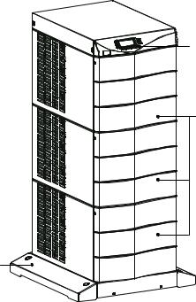
The Eaton 9170+ UPS is available in four cabinet sizes. Figure 1 through Figure 6 show the 3-slot and 9-slot configurations and identify basic Eaton 9170+ system features. Six-slot and 12-slot cabinets are also available; external battery cabinets are available in 6-, 9-, and 12-slot sizes.
Front Panel
Display
Front Cover
|
Figure 1. Three-Slot Cabinet (Front View) |
Communication |
DB-9 |
Slots |
Communication |
|
Port |
Power Outlets |
|
(optional) |
|
Input Power
Cable (optional)
Figure 2. Three-Slot Cabinet (Rear View)
Eaton 9170+ UPS (3–18 kVA) User's Guide S 164201393 Rev E www.eaton.com/powerquality |
5 |
INTRODUCTION
Front Panel Display
Front Cover
Cabinet Base
Figure 3. Nine-Slot Cabinet (Front View)
6 |
Eaton 9170+ UPS (3–18 kVA) User's Guide S 164201393 Rev E www.eaton.com/powerquality |

INTRODUCTION
|
DB-9 Communication Port |
Communication |
Wiring Access |
Slots |
|
Power Outlets (optional)
Input Power
Cable (optional)
|
Figure 4. Nine-Slot Cabinet (Rear View) |
Handle/Latch |
Handle |
Release |
|
|
Thumbscrew |
Insertion/Extraction
Cams
Figure 5. Power Module (ASY-0673 and ASY-0674)
Secondary Stop
Release
Latch Release
Figure 6. Battery Module (ASY-0529)
Eaton 9170+ UPS (3–18 kVA) User's Guide S 164201393 Rev E www.eaton.com/powerquality |
7 |
INTRODUCTION
8 |
Eaton 9170+ UPS (3–18 kVA) User's Guide S 164201393 Rev E www.eaton.com/powerquality |

Chapter 2 Installation Setup
This chapter explains how to set up and install the Eaton 9170+ cabinets:
SSetup, including clearances and location requirements
SCaster cart installation (for 3- and 6-slot cabinets)
SStabilizer bracket installation (for 12-slot cabinets)
SRack-mount installation (for 3- and 6-slot cabinets)
SFloor anchor kit installation
SMoving the cabinets
Equipment Clearances
All cabinet sizes require the following clearances to allow for servicing and adequate ventilation:
SSides: 15.2 cm (6”)
STop and back: 30.5 cm (12”)
SFront: 91.5 cm (36”)
If flexible conduit connects the UPS to the service input and load distribution panels, you may be able to gain access for servicing by moving the UPS. If this is the case, you must still leave 30.5 cm (12”) clearance at the back and 15.2 cm (6”) at the sides of the UPS for ventilation.
NOTE Do not block the ventilation holes on each side and the back of the cabinet.
Nineand 12-slot external battery cabinets may be installed with bases tight against the UPS cabinet base and against each other. Six-slot cabinets require 15.2 cm (6”) of separation.
Eaton 9170+ UPS (3–18 kVA) User's Guide S 164201393 Rev E www.eaton.com/powerquality |
9 |

INSTALLATION SETUP
Location Requirements
Install the Eaton 9170+ UPS as close as possible to the equipment or the load distribution panel it will protect. If this distance is more than 7.6m (25 ft), transient noise can reappear in the electrical distribution system.
If a separate external battery cabinet is installed, the battery cabinets must be adjacent to the Eaton 9170+ UPS. If the batteries will be farther from the cabinet than the standard cables allow, contact your service representative or your local distributor for assistance.
UPS Setup
The Eaton 9170+ UPS is shipped in a carton on a shipping pallet. Power and battery modules are shipped in separate boxes on another pallet. Three-slot cabinets and modules are shipped on one pallet. Refer to the unpacking instruction sheet (LTS-1724) packed inside the UPS shipping carton.
NOTE Verify that all Eaton 9170+ UPS power modules are the proper type for the UPS cabinet: Split-phase power modules have brown labels; universal (single-phase) power modules have black labels. Do not mix brown and black modules in the same UPS cabinet.
Threeand Six-Slot Cabinets
NOTE Do not attempt to lift the cabinet by the module shelves or other convenient edges or covers.
To set up 3- or 6-slot cabinets:
1.Place the cabinet in its intended operating location.
2.If an optional caster cart is included for cabinet mobility, see “Caster Cart Installation (Threeand Six-Slot Cabinets)” on page 12 to mount the cabinet on the cart and stabilize it using the cart foot pads.
3.Cut the lifting straps or slip them off the cabinet base tabs.
4.If an optional floor anchor kit is included for extra stability, see ”Floor Anchor Kit Installation” on page 16 to install the floor anchor brackets.
10 |
Eaton 9170+ UPS (3–18 kVA) User's Guide S 164201393 Rev E www.eaton.com/powerquality |

INSTALLATION SETUP
5.If installing the 3- or 6-slot cabinet in a rack, see ”Rack-Mount Installation (Threeand Six-Slot Cabinets)” on page 14 to install the cabinet in the rack.
6.If you are installing an external battery cabinet, continue to “Battery Cabinet Installation” on page 61.
If you do not have an external battery cabinet, continue to “UPS Startup” on page 67 for plug-receptacle units. For hardwired units, continue to “UPS with Bypass Electrical Installation” on page 19 or “UPS Electrical Installation” on page 39.
Nineand Twelve-Slot Cabinets
C A U T I O N
Do NOT lower the casters or attempt to move the cabinet with the power or battery modules installed.
To set up 9- or 12-slot cabinets:
1.Lower the four cabinet casters (one at each corner of the cabinet base) by using a 1/2” hex-style socket wrench to turn each bolt clockwise.
2.With all casters fully extended, carefully roll the cabinet down the ramp to its intended operating location.
NOTE For 12-slot cabinets. Before moving the 12-slot cabinet to its intended operating location, see “Stabilizer Bracket Installation (Twelve-Slot Cabinet Only)” on page 13 to install two stabilizer brackets.
3.Stabilize the cabinet in its operating location by turning the four caster bolts counter-clockwise until the cabinet rests on the floor. Place a plastic cap into each bolt access hole.
NOTE If the floor is uneven and the cabinet is tilted or unstable, you may need to place a thin steel plate under a corner. Do not use the caster bolts to level the cabinet.
4.If an optional floor anchor kit is included for extra stability, see ”Floor Anchor Kit Installation” on page 16 to install the floor anchor brackets.
Eaton 9170+ UPS (3–18 kVA) User's Guide S 164201393 Rev E www.eaton.com/powerquality |
11 |
INSTALLATION SETUP
5.If installing the 9- or 12-slot cabinet in a rack, follow the installation instructions with the 9- and 12-slot rack-mount kit.
6.If you are installing an external battery cabinet, continue to “Battery Cabinet Installation” on page 61.
If you do not have an external battery cabinet, continue to “UPS Startup” on page 67 for plug-receptacle units. For hardwired units, continue to “UPS with Bypass Electrical Installation” on page 19 or “UPS Electrical Installation” on page 39.
Caster Cart Installation (Threeand Six-Slot Cabinets)
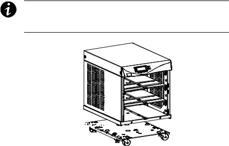
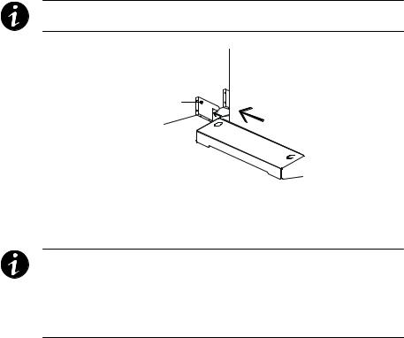
An optional caster cart (ASY-0527) is available for 3- and 6-slot cabinets for increased mobility of the UPS (see Figure 7).
NOTE The UPS cabinet is heavy (see page 105). This procedure requires two people to lift and position the cabinet onto the caster cart. Lift the cabinet using four lifting straps shipped with the cabinet; do not attempt to lift the cabinet by the module shelves or other convenient edges or covers.
Caster Cart 


Figure 7. Three-Slot Cabinet Being Lowered onto Caster Cart
12 |
Eaton 9170+ UPS (3–18 kVA) User's Guide S 164201393 Rev E www.eaton.com/powerquality |
INSTALLATION SETUP
To install the caster cart:
1.Place the caster cart (shipped separately from the UPS cabinet) under the cabinet before installing power and battery modules and before making connections to the intended power source.
The cart requires no bolts or other hardware to fasten it to the UPS cabinet. It is shaped to fit securely under the cabinet, ensuring proper alignment after placing the cabinet on the cart.
2.Four foot pads under the cart keep the cart from rolling when it is in its intended location. Turn each threaded foot to lower it to the floor. When the foot is tight against the floor, turn the locknut on the threaded foot up tight against the bottom of the cart to keep the foot from rotating.
3.If leveling of the UPS is required, use the foot pads to raise a side or corner before locking them with their locknuts.
Stabilizer Bracket Installation (Twelve-Slot Cabinet Only)
The 12-slot Eaton 9170+ UPS cabinet is shipped with two stabilizer brackets. These brackets must be attached to the wall or the floor behind the UPS cabinet. Under all module-loading conditions, they act as a protective stop to prevent the cabinet from falling forward if it is unintentionally pushed away from the wall.
Each bracket has holes that enable it to be attached by screws to either the wall or the floor (or both) behind the intended cabinet installation (see Figure 8). The stabilizer brackets are not attached to the cabinet base itself.
To install the stabilizer brackets:
1.Select the location for the brackets, approximately 30–41 cm (12–16”) apart, at the floor/wall intersection behind the intended cabinet location.
2.Using the proper type of customer-supplied screws for the intended mounting surface, attach each bracket as shown in Figure 8. All screws must be driven into structural material such as wall studs.
3.Roll the UPS cabinet to its intended location. Position the rear section of the cabinet base under the open ends of the stabilizer brackets as far as the cabinet will go.
Eaton 9170+ UPS (3–18 kVA) User's Guide S 164201393 Rev E www.eaton.com/powerquality |
13 |
INSTALLATION SETUP
4.Turn all four caster bolts counter-clockwise until the cabinet rests on the floor. Place a plastic cap into each bolt access hole.
NOTE If the floor is uneven and the cabinet is tilted or unstable, you may need to place a thin steel plate under a corner. Do not use the caster bolts to level the cabinet.
Stabilizer Bracket
Figure 8. Stabilizer Bracket Installation
Rack-Mount Installation (Threeand Six-Slot Cabinets)
NOTE For 9- and 12-slot cabinets, follow the installation instructions with the 9- and 12-slot rack-mount kit.
NOTE The UPS cabinet is heavy (see page 105). This procedure requires two people to lift and position the cabinet into the equipment rack. Install the cabinet in the rack before installing power and battery modules and before making connections to the intended power source.
The 3- and 6-slot UPS cabinets may be installed in an EIA-standard
48.3 cm (19”) equipment rack. An optional rack-mounting kit (ASY-0547), containing brackets and required hardware, is available.
For each 3-slot section, use the following mounting procedure to convert the UPS cabinet and install it in the equipment rack:
1.Remove the four screws (two on either side) securing the top cover of the UPS cabinet. Carefully lift the cover straight up and off to avoid stressing the front panel display. Set the cover aside.
2.Remove the two cabinet side covers (four covers in 6-slot cabinets) by lifting the top edge. No other hardware must be detached. Store or discard the side covers.
14 |
Eaton 9170+ UPS (3–18 kVA) User's Guide S 164201393 Rev E www.eaton.com/powerquality |
INSTALLATION SETUP
3.Carefully replace the UPS cabinet top cover and secure with the four screws removed in Step 1. Position the cover lip to fit behind the front panel display.
4.Install three metal clip nuts onto each side flange (six clip nuts on 6-slot cabinets) along the front of the UPS cabinet (see Figure 9).
Tab Slots
Metal Clip Nuts
Figure 9. Metal Clip Nut and Tab Slot Locations
5.Install a rack-mount ear (two for 6-slot cabinets) on each side of the UPS cabinet (see Figure 10).
Insert the two offset tabs on the rear edge of the ear into the matching tab slots on the cabinet side frame (see Figure 9). Pivot the ear forward until it is flush against the UPS cabinet side frame. Using three 1/4-20 1/2” Phillips-head bolts, screw the bolts into the metal clip nuts installed in Step 4.
Rack-Mount Ear 


Figure 10. Rack-Mount Ear Installed
Eaton 9170+ UPS (3–18 kVA) User's Guide S 164201393 Rev E www.eaton.com/powerquality |
15 |

INSTALLATION SETUP
6.Select the position for the UPS in the equipment rack.
7.Select the proper holes in the rail that position the UPS at the desired location in the rack.
8.With one person lifting each side of the UPS cabinet, carefully slide the UPS into the equipment rack until the rack-mount ears of the cabinet are flush with the front vertical rails of the rack. Verify that the holes in the ears align with the holes in the rack.
9. Secure the UPS in the rack using eight 10-32 1/2” Torx® screws (16 for 6-slot cabinets) or other appropriate customer-specified screws.
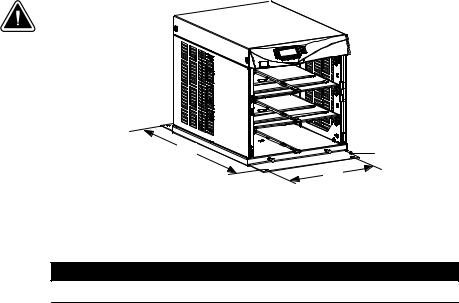
Floor Anchor Kit Installation
An optional floor anchor kit (ASY-0548) is available for all sizes of the Eaton 9170+ UPS. The kit helps to stabilize the UPS or battery cabinet in the event of accidental bumps or small floor movements. Any testing to specific seismic requirements is the responsibility of the customer.
The floor anchor brackets, shipped separately from the UPS and battery cabinet, should be attached inside the lower front and rear edges of the cabinet before installing power and battery modules and before making connections to the intended power source.
Use mounting hardware supplied with the floor anchor kit to attach the brackets to the UPS or external battery cabinet (see Figure 11). The customer is responsible for specifying and supplying floor mounting bolts.
Mounting Centers for 8 mm (5/16”) Floor Bolts
Dimension (see Figure 11) |
Measurement |
|
|
|
|
A |
36.8 cm (14.5”) |
|
|
|
|
B (3- and 6-slot cabinets) |
76.8 cm (30.25”) |
|
|
|
|
B (9- and 12-slot cabinets) |
87 cm (34.25”) |
|
|
|
|
16 |
Eaton 9170+ UPS (3–18 kVA) User's Guide S 164201393 Rev E www.eaton.com/powerquality |
INSTALLATION SETUP
B |
Floor Anchor |
Bracket |
A
Figure 11. Floor Anchor Brackets Bolted to UPS Cabinet
Moving the Cabinets
C A U T I O N
Do NOT attempt to raise the cabinet with the power or battery modules installed.
The Eaton 9170+ UPS and the battery cabinet are very heavy with power and battery modules installed. Before moving the cabinets, remove the power and battery modules. Move the modules separately from the cabinets.
The 3- and 6-slot cabinets may be ordered with a caster cart to enable moving the cabinet. “Caster Cart Installation (Threeand Six-Slot Cabinets)” on page 12 describes how to set the four foot pads on this cart to keep the cabinet from rolling when properly positioned.
The 9- and 12-slot cabinets have casters built into the cabinet base. To raise the cabinet before rolling it on its casters:
1.Verify that the cabinet contains no power or battery modules.
2.For 12-slot cabinets. Slide the cabinet base out from under the stabilizer brackets in the rear section of the cabinet base.
Remove the stabilizer brackets from the floor/wall. Follow the instructions in “Stabilizer Bracket Installation” on page 13 to reinstall the stabilizer brackets in the new location.
3.Locate the four plastic caps covering the caster bolts. They are at the corners of the cabinet base.
Eaton 9170+ UPS (3–18 kVA) User's Guide S 164201393 Rev E www.eaton.com/powerquality |
17 |

INSTALLATION SETUP
4.Pry the caps out of the bolt access holes.
5.Use a 1/2” hex-style socket wrench to turn each of the four bolts clockwise. Doing so lowers the casters to allow the cabinet to roll on the casters.
6.After rolling the cabinet to its intended position, turn all four caster bolts counter-clockwise until the cabinet rests on the floor. Place a plastic cap into each bolt access hole.
NOTE If the floor is uneven and the cabinet is tilted or unstable, you may need to place a thin steel plate under a corner. Do not use the caster bolts to level the cabinet.
7.After properly positioning and leveling the cabinet, insert power and battery modules into the cabinet as described in “Power and Battery Module Installation” on page 67.
18 |
Eaton 9170+ UPS (3–18 kVA) User's Guide S 164201393 Rev E www.eaton.com/powerquality |
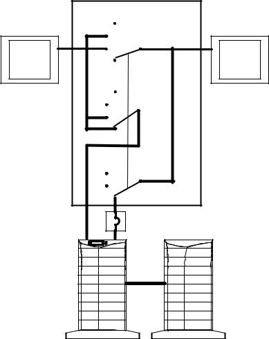
Chapter 3 UPS with Bypass Electrical Installation
NOTE If you have a plug-receptacle unit, continue to “Battery Cabinet Installation” on page 61 for installing optional battery cabinets or to “UPS Startup” on page 67.
W A R N I N G
Only qualified service personnel (such as a licensed electrician) should perform the electrical installation. Risk of electrical shock.
The Eaton 9170+ UPS input power may be hardwired through conduit to either a main power source circuit breaker or to an optional external bypass switch. For hardwired installations, it is recommended that you install an Eaton bypass switch to enable power transfer during maintenance or UPS downtime. If a bypass switch is used, both UPS input and UPS output must be hardwired — through separate
conduits — to the bypass switch, as shown in Figure 12.
Eaton 9170+ UPS (3–18 kVA) User's Guide S 164201393 Rev E www.eaton.com/powerquality |
19 |
UPS WITH BYPASS ELECTRICAL INSTALLATION
Building
Service
Panel
External Bypass Switch
Off
Service
Line
UPS
Off
Service
Line
UPS
Off 
Service
Line
UPS 
User-Supplied
(if required)
Load
Distribution
Panel
External Batteries
(optional)
Figure 12. Typical Installation with a Bypass Switch
20 |
Eaton 9170+ UPS (3–18 kVA) User's Guide S 164201393 Rev E www.eaton.com/powerquality |
UPS WITH BYPASS ELECTRICAL INSTALLATION
Input Current Ratings
Table 1 contains the required circuit breaker ratings for hardwired installations. Circuit breaker ratings for units having an input line cord are determined by the current capacity of the line cord.
Table 1. Required Input Circuit Breaker Sizes (200–240 Vac, 50/60 Hz)
UPS Capacity |
Input Circuit Breaker Rating |
|
|
3 kVA |
25A |
|
|
6 kVA |
40A |
|
|
9 kVA |
60A |
|
|
12 kVA |
80A |
|
|
15 kVA |
100A |
|
|
18 kVA |
125A |
|
|
NOTE If you are installing an optional battery charger module, refer to that user's guide for the proper input circuit breaker sizes and ratings.
C A U T I O N
To accommodate the feature of easy system expandability, it is recommended that initial installation of the Eaton 9170+ UPS contains wiring to support the maximum capacity of the UPS cabinet: 3 kVA for 3-slot cabinets; 9 kVA for 6-slot cabinets; 18 kVA for 9- and 12-slot cabinets. See Table 16 and Table 17 starting on page 98.
Eaton 9170+ UPS (3–18 kVA) User's Guide S 164201393 Rev E www.eaton.com/powerquality |
21 |
UPS WITH BYPASS ELECTRICAL INSTALLATION
See Table 2 for recommended conductor sizes to wire the input circuit breakers.
Table 2. Recommended Wire Sizes
Input Circuit Breaker Size |
75°C Copper Wire Size |
Conductor Screw Torque |
|
|
|
25A |
5.3 mm2 (10 AWG) |
4.0 Nm (35 lb in) |
40A |
8.4 mm2 (8 AWG) |
4.5 Nm (40 lb in) |
60A |
21.2 mm2 (4 AWG) |
5.1 Nm (45 lb in) |
80A |
26.7 mm2 (3 AWG) |
6.6 Nm (50 lb in) |
100A |
33.6 mm2 (2 AWG) |
6.6 Nm (50 lb in) |
125A |
42.1 mm2 (1 AWG) |
6.6 Nm (50 lb in) |
FOR U.S. INSTALLATIONS, READ THIS IMPORTANT NOTE!
This table lists the mm2 and AWG wire size for each circuit breaker size shown on the wiring diagrams. The minimum recommended circuit breaker sizes for each model and voltage application are listed on the wiring diagrams.
Conductor sizes shall be no smaller than the 75°C wire size based on the ampacities given in Table 310–16 of the National Electrical Code, ANSI/NFPA 70-1999, and article 220. All circuit conductors, including the neutral conductor, must be the same size (ampacity) wire. Code may require a larger AWG size than shown in this table because of temperature, number of conductors in the conduit, or long service runs.
Follow local code requirements.
Bypass Switches
Bypass switches are available in two types: Make-Before-Break (MBB) and Break-Before-Make (BBM).
An MBB switch makes a new connection before it breaks the original connection. For example, if you turn an MBB switch from UPS to LINE, the bypass switch connects the load to AC input power before disconnecting the load from UPS output power. (As noted in Figure 38 on page 57, MBB switches may not be used in certain system configurations.)
A BBM switch breaks the original connection before it makes a new one. If you turn a BBM switch from UPS to LINE, the switch disconnects the load from UPS output power before connecting the load to AC input power.
The bypass switch has four positions as described in Table 3.
22 |
Eaton 9170+ UPS (3–18 kVA) User's Guide S 164201393 Rev E www.eaton.com/powerquality |

|
|
UPS WITH BYPASS ELECTRICAL INSTALLATION |
|
|
|
|
|
|
|
NOTE In the UPS or LINE position, AC input power is still connected to the input terminals |
|
|
|
inside the UPS. |
|
|
|
|
|
Table 3. Bypass Switch Positions |
|||
|
|
||
Switch Position |
Description |
||
|
|
||
LINE |
Connects the load directly to AC input power and disconnects UPS output. AC input power is |
||
|
still connected to the UPS input. |
||
|
|
||
OFF |
Disconnects the load from the UPS output power and AC input power, as well as AC input |
||
|
power to the UPS input. |
||
|
|
||
UPS |
Connects the UPS output to the load. |
||
|
|
||
SERVICE |
Like the LINE position, SERVICE connects the load directly to AC input power and disconnects |
||
|
UPS output. However, because SERVICE also disconnects AC input from the UPS, this is |
||
|
the appropriate position for UPS maintenance or repair. |
||
|
|
|
|
Bypass Switch Operation
The bypass switch consists of a load position handle and a red button (see Figure 13).
The red button:
S Sends an electrical signal to the UPS to switch to the internal Bypass mode (if it is not already operating in that mode).
S Operates a mechanical interlock, to prevent the switch from being turned without first signaling the UPS.
For MBB switches, you must press the red button before you can turn the load position handle.
When the red button is pressed the UPS front panel displays “Manual
Bypass.” The load position handle can now be turned from the UPS to
LINE position or from the LINE to UPS position.
Eaton 9170+ UPS (3–18 kVA) User's Guide S 164201393 Rev E www.eaton.com/powerquality |
23 |

UPS WITH BYPASS ELECTRICAL INSTALLATION
After turning the load position handle to the UPS position and releasing the red button, the Eaton 9170+ UPS remains in Bypass mode. For proper operation, return the UPS to Auto mode using the following procedure.
NOTE If the UPS remains in Manual Bypass mode and incoming AC power is lost, the load is automatically dropped. The UPS must be in Auto mode to provide battery backup power.
NOTE If you have any questions or problems with the bypass operation, call the Help Desk at one of the telephone numbers on page NO TAG and ask for a UPS technical representative.
1.Press the menu button on the front panel display (see Figure 54 on page 80). The System Status Menu displays.
2.Press the B button until the System Control menu displays.
3.Press the 
 button. Mode Preference displays.
4.Press the 
 button to access Mode Preference. The Enter Password screen automatically opens.
5.Enter the appropriate password (0377 is the default), then press the

 button.
6.Press the 
 button again and press the B button until you see Auto.
7.Press the 
 button and listen for a click.
8.Press ESC twice to return to the System Status Menu. The UPS is now in Auto mode.
To disconnect AC input power during maintenance or service, turn the bypass switch to the SERVICE position.
Table 4 shows the bypass switch models available for the Eaton 9170+
UPS.
24 |
Eaton 9170+ UPS (3–18 kVA) User's Guide S 164201393 Rev E www.eaton.com/powerquality |
Loading...