


350
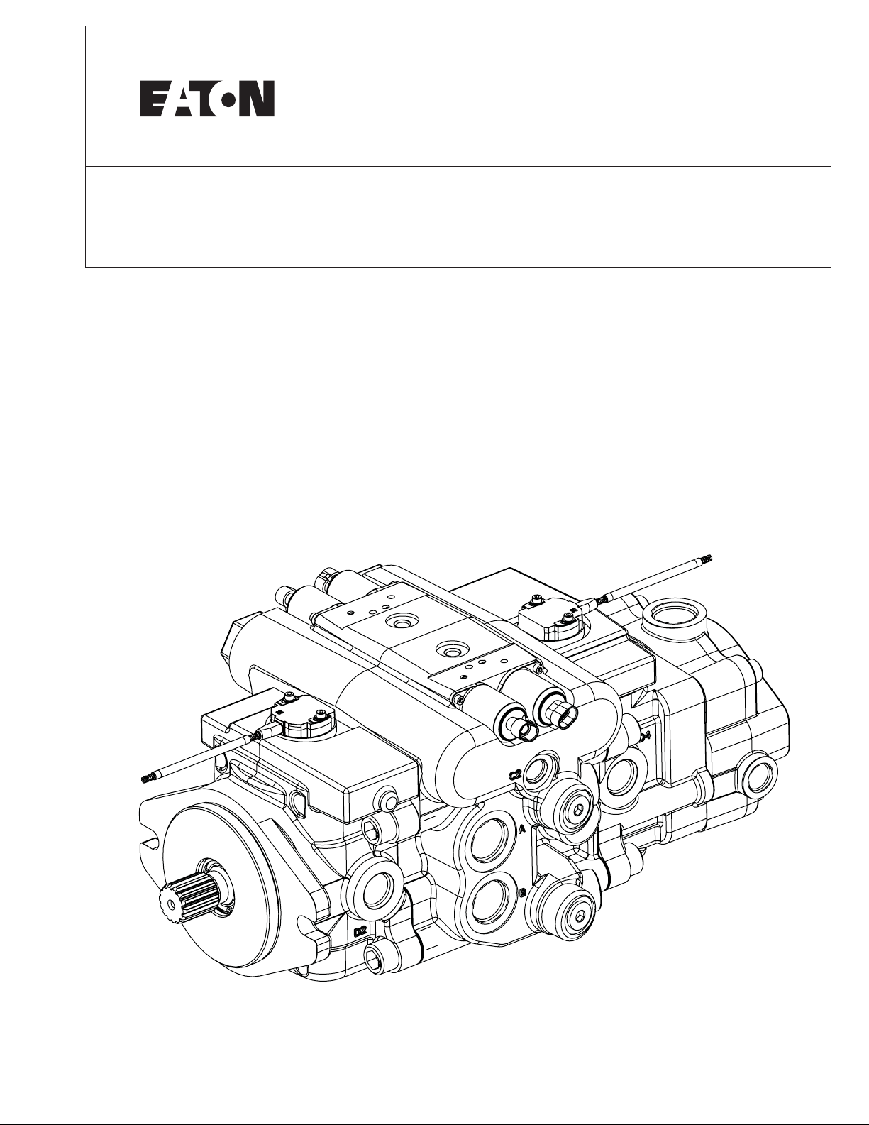
Dual Path Mobile Pumps
Parts and Repair Manual
350 Series

2
EATON 350 Series Dual Path Mobile Pumps E-PUPI-TS006-E September 2007
Introduction ....................................................................................2
Exploded View................................................................................3
Parts List ........................................................................................5
Model Code....................................................................................8
Rotating Kit Assembly ..................................................................10
Drive Shafts..................................................................................13
Relief Valv e Sub-Assembly............................................................14
Housing Identification ..................................................................14
Servo Piston Assembly ................................................................15
Index of Mechanical Servo Controllers,
Control Valve Sub-Assemblies......................................................16
Charge Pump Adapter Assumbly..................................................24
Assembly......................................................................................25
Required T ools..........................................................................25
Swash Plate Sub-Assembly......................................................26
Mechanical Servo Control........................................................27
Rotating Kit Asembly................................................................29
Servo Piston Assembly............................................................30
Dual Pump Housing Assembly ................................................31
Rear Pump Assembly ..............................................................32
Front Pump Assembly ..............................................................35
Troubleshooting ..........................................................................39
Start-Up Procedure ......................................................................44
How T o Order................................................................................45
Table of Contents
Introduction
This manual provides service
information for the Eaton
Model 350 Series Piston
Pumps. Step-by-step instr uctions
for the complete assembly
of the pump are given. For
dis-assembly , follow the reverse
of the assembly instructions.
These recommendations
should be followed to insure
successful repairs.
• Remove the pump from the
vehicle.
• Cleanliness is extremely
important.
• Clean the port areas thoroughly before disconnecting
the hydraulic lines.
• Plug the pump ports and
cover the open hydraulic
lines immediately after
they’re disconnected.
• Drain the oil and clean the
exterior of the pump before
making repairs.
• Wash all metal parts in
clean solvent.
• Use compressed air to dry
the parts. Do not wipe them
dry with paper towels or
cloth.
• The compressed air should
be filtered and moisture
free.
• Always use new seals when
reassembling hydraulic
pumps.
• Lubricate the new rubber
seals with a petroleum jelly
(Vaseline) before installation.
• Torque all bolts over gasketed
joints, then repeat torquing
sequence to make up for
gasket compression.
• Verifying the accuracy of
pump repairs on an authorized
test stand is essential.
3
EATON 350 Series Dual Path Mobile Pumps E-PUPI-TS006-E September 2007
77
89
60
60
61
61
59
70
71
72
1
43, 44, 45, 46
43, 44, 45, 46
75
74
53, 88
53, 88
87
90
90
51, 52
50
47
6
7
2, 3, 4, 5, 6, 73
13
39
54
48, 49
30
6, 7, 8
7
15
89
16
31
20, 33
22, 35
42
76
59
47
17
41
27
55
57, 58
56
25
24
42
10
54
26
30
9, 10, 11, 12
29
21
20, 33
14
17
15
16
18
28
22, 35
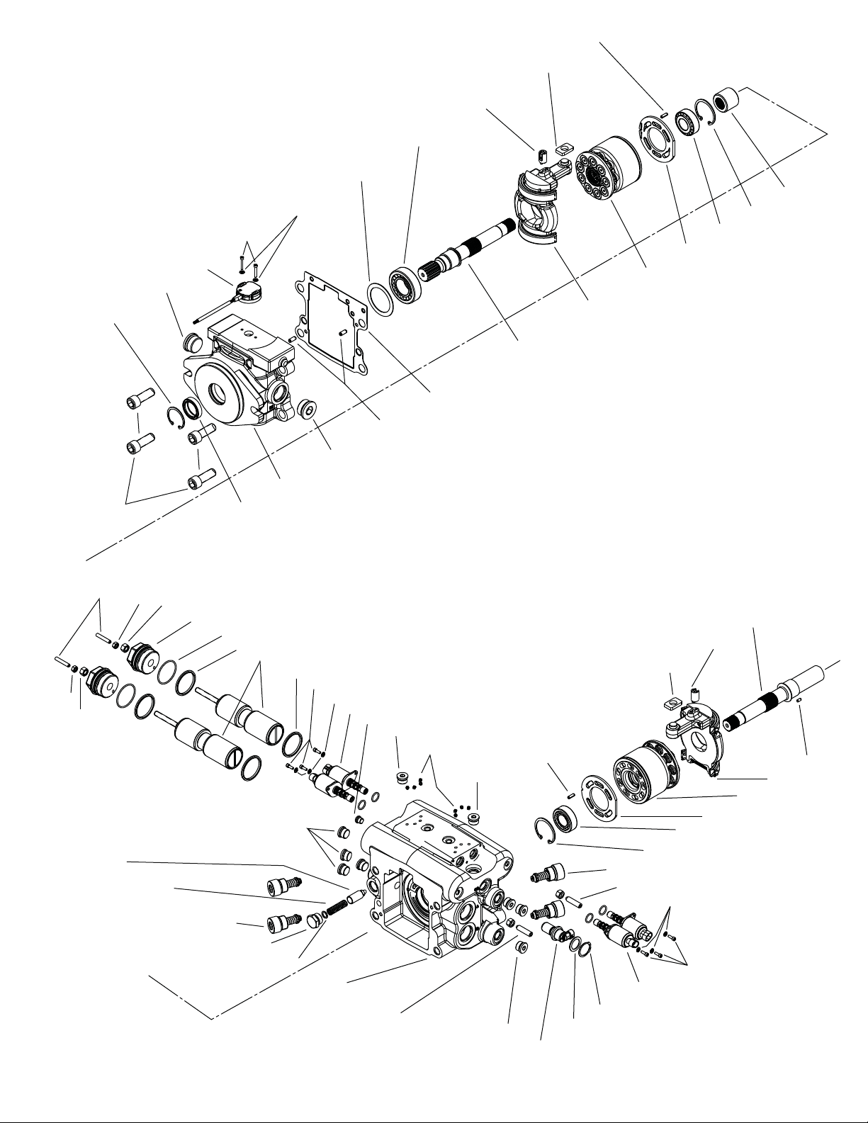
Part s -
Exploded View
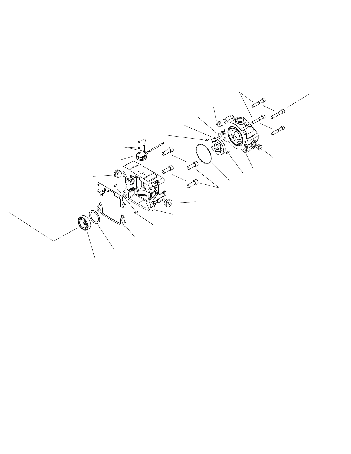
Part s -
Exploded View
4
EATON 350 Series Dual Path Mobile Pumps E-PUPI-TS006-E September 2007
37
12
55
57, 58
56
79
78
79
83
81
84
85, 86
85, 86
38
34
29
40
11
41
82
Note: Investigating having this
page fold out from page 3 so that
Parts drawings are together

5
EATON 350 Series Dual Path Mobile Pumps E-PUPI-TS006-E September 2007
Parts List
1 1 5989802-XXX* Housing with Control Assembly HA, MA, MB, MC, MD, ME, MF and Main Ports A & B
1 1 5989803-XXX* Housing with Control Assembly SA, SB, SC and Main Ports A & B
1 1 5989804-XXX* Housing with Control Assembly HA, MA, MB, MC, MD, ME, MF and Main Port C
1 1 5989805-XXX* Housing with Control Assembly SA, SB, SC and Main Port C
2-5 7 16103-308 Plug Assembly
6-8 3 16103-304 Plug Assembly
9-12 4 16103-316 Plug Assembly
13 8 472187 Plug Expander Type
14 1 5986543-001 Coupler
15 2 16077-033 Retaining Ring
16 2 5988198-001 Bearing, Taper
17 2 16026-610 Pin, Roll
18 1 5990287-001 Valve Plate, LH (2.50) - 41cc
1 5990288-001 Valve Plate, RH (2.50) - 41cc
1 5990289-001 Valve Plate, LH (3.00) - 49cc
1 5990290-001 Valve Plate, RH (3.00) - 49cc
1 5987231-001 Valve Plate, LH (3.80) - 62cc
1 5986812-001 Valve Plate, RH (3.80) - 62cc
20 1 4999504-001 Rotating Kit LH (2.50) - 41cc
1 5991532-001 Rotating Kit RH (2.50) - 41cc
1 4999502-001 Rotating Kit LH (3.00) - 49cc
1 5991530-001 Rotating Kit RH (3.00) - 49cc
1 4999506-001 Rotating Kit LH (3.80) - 62cc
1 5991720-001 Rotating Kit RH (3.80) - 62cc
21 1 5989712-001 Gasket, Flange
22 1 5990298-001 Swashplate Sub-assembly
24 1 5988197-001 Bearing, Taper
25 A/R 114746-XXX Shim
26 1 4993012-003 Shaft Seal A, High Pressure Polyacryalate
1 16253-020 Shaft Seal B, High Pressure Nitrile
27 1 16077-028 Ring, Retaining Internal
28 1 5987541-001 Drive Shaft - Front 4-Bolt C (14T)
1 5989544-001 Drive Shaft - Front 2-Bolt C (14T)
1 5991587-001 Drive Shaft - Front 2-Bolt B (Dia. 1.00 taper)
1 5992243-001 Drive Shaft - Front 2-Bolt B (15T)
1 5992425-001 Drive Shaft - Front 2-Bolt C (19T)
1 5993096-001 Drive Shaft - Front 2-Bolt B (14T)
29 4 16026-810 Pin, Roll
30 1 5990395-XXX* Flange, Front 4-Bolt C (Manual)
1 5990396-XXX* Flange, Front 4-Bolt C (Solenoid)
1 5990398-XXX* Flange, Front 2-Bolt C (Manual)
1 5990399-XXX* Flange, Front 2-Bolt C (Solenoid)
1 5990095-XXX* Flange, Front 2-Bolt B (Manual)
1 5990096-XXX* Flange, Front 2-Bolt B (Solenoid)
1 5993095-XXX* Flange, Front 2-Bolt B (HRC)
1 5991841-XXX* Flange, Front 2-Bolt C (HRC)
31 1 5990287-001 Valve Plate LH (2.50) - 41cc
1 5990288-001 Valve Plate RH (2.50) - 41cc
1 5990289-001 Valve Plate LH (3.00) - 49cc
1 5990290-001 Valve Plate RH (3.00) - 49cc
1 5987231-001 Valve Plate LH (3.80) - 62cc
1 5986812-001 Valve Plate RH (3.80) - 62cc
ITEM # QTY PART # DESCRIPTION
* Reference individual assembly parts lists for further detail.
A/R - as required

6
EATON 350 Series Dual Path Mobile Pumps E-PUPI-TS006-E September 2007
Parts List
ITEM # QTY PART # DESCRIPTION
33 1 4999504-001 Rotating Kit LH (2.50) - 41cc
1 5991532-001 Rotating Kit RH (2.50) - 41cc
1 4999502-001 Rotating Kit LH (3.00) - 49cc
1 5991530-001 Rotating Kit RH (3.00) - 49cc
1 4999506-001 Rotating Kit LH (3.80) - 62cc
1 5991720-001 Rotating Kit RH (3.80) - 62cc
34 1 5989712-001 Gasket, Flange
35 1 5990298-001 Swashplate Sub-Assembly
37 1 5988197-001 Bearing, Taper
38 A/R 114746-001 Shim
39 1 5987349-001 Drive Shaft - Rear (15T w/ Charge Pumps 1, 2)
1 5987349-002 Drive Shaft - Rear (15T w/ Charge Pumps 3, 4)
1 5989545-001 Drive Shaft - Rear (15T w/o Charge Pump)
1 5991280-001 Drive Shaft - Rear (13T w/ Charge Pumps 1, 2)
1 5991280-002 Drive Shaft - Rear (13T w/ Charge Pumps 3, 4)
1 5991466-001 Drive Shaft - Rear (13T w/o Charge Pump)
1 5992244-001 Drive Shaft - Rear (11T w/o Charge Pump)
40 1 5990401-XXX* Flange, Rear 2-Bolt B (Manual)
1 5990402-XXX* Flange, Rear 2-Bolt B (Solenoid)
1 5991202-XXX* Flange, Rear Charge Pump (Manual)
1 5991203-XXX* Flange, Rear Charge Pump (Solenoid)
1 5992240-XXX* Flange, Rear 2-Bolt A (Manual)
1 5992241-XXX* Flange, Rear 2-Bolt A (Solenoid)
1 5991842-XXX* Flange, Rear Charge Pump (HRC)
1 5992242-XXX* Flange, Rear 2-Bolt A (HRC)
1 5996777-XXX* Flange, Rear 2-Bolt B (HRC)
41 8 114978-045 Screw, Cap, Hex Socket Head
42 2 4999637-001 Follower, Servo Piston
43-46 1 110700-XXX Relief Valve Sub-assembly (reference page 13 for further detail)
47 4 5987241-001 Piston Ring
48 1 5989959-001 Servo Piston Sub-assembly (Used with Controls: MA, MB, MC, MD, MF, SA, SB, SC)
1 5989958-001 Servo Piston Sub-assembly (Used with Control: HA)
49 1 5989959-001 Servo Piston Sub-assembly (Used with Controls: MA, MB, MC, MD, MF, SA, SB, SC)
1 5989958-001 Servo Piston Sub-assembly (Used with Control: HA)
50 2 16015-34 O-Ring
51 1 5989898-001 Servo Cap Plug
1 5991129-001 Servo Cap Plug
52 1 5989898-001 Servo Cap Plug
1 5991129-001 Servo Cap Plug
53 2 5996839-001 Nut, Sealing
54 2 5990203-001 Magnet Carrier
55 2 5990202-001 Feedback Sensor (SB) - Control
2 5990202-002 Feedback Sensor (SA) - Control
56 4 5996053-002 Screw
57 4 4994180-016 Washer
58 4 16133-208 O-Ring
59 4 5991234-001 Proportional Flow Regulator (SA Control)
60 6 95897-008 Washer
61 6 16147-204 Screw, Cap, Hex Socket Head
62 2 4999960-001 Feedback Control Link
63 2 5987239-001 Gasket
* Reference individual assembly parts lists for further detail.
A/R - as required

7
EATON 350 Series Dual Path Mobile Pumps E-PUPI-TS006-E September 2007
ITEM # QTY PART # DESCRIPTION
64 1 5986768-XXX* Control Valve Sub-assembly
65 1 5986768-XXX* Control Valve Sub-assembly
66 12 114975-025 Screw, Cap, Hex Socket Head
67 2 95729-000 Control Lever
68 2 16045-205 Lockwasher
69 2 16021-5 Nut
70 1 4995422-001 Magnetic Speed Sensor
71 1 16048-077 Washer
72 1 16160-125 Retaining Ring, Inverted Internal
73 1 16103-308 Plug Sub-assembly
74 1 4998532-001 Poppet
75 1 4998533-001 Spring, Compression
76 A/R 16048-597 Shim
77 1 72400-659 Plug Sub-assembly
78 1 16015-055 O-Ring
79 2 16026-810 Pin, Roll
80 1 101305-000 Charge Pump Drive Pin
81 1 5987263-XXX* Gerotor Sub-assembly
82 2 16003-013 O-Ring
83 1 5991128-XXX* Charge Pump Adapter (RH Rotation)
1 5991230-XXX* Charge Pump Adapter (LH Rotation)
84 4 114977-070 Screw, Cap, Hex Socket Head
85, 86 1 16103-310 Plug Sub-assembly
87 2 16139-644 Set Screw
88 2 5996839-001 Nut, Sealing
89 2 16139-444 Set Screw
90 2 5996838-001 Nut, Sealing
91 1 5991133-001 Actuator, Bypass Valve - Main Ports A, B, D, E
92 2 5991131-001 Actuator, Bypass Valve - Main Ports C, F
Parts List
* Reference individual assembly parts lists for further detail.
A/R - as required
8
EATON 350 Series Dual Path Mobile Pumps E-PUPI-TS006-E September 2007
Model Code
Code Title
AED – Dual Ser vo Controlled
Variable Displacement Axial
Piston Pump
Displacement & Rotating
Kit- Front
1 – 41.0 cm3/r [2.50 in3/r]
2 – 49.2 cm
3
/r [3.00 in3/r]
3 – 62.3 cm
3
/r [3.80 in3/r]
4 – 35.0 cm
3
/r [2.10in3/r]
Destroked from -
41.0 cm
3
/r [2.50 in3/r]
5 – 45.0 cm
3
/r [2.75 in3/r]
Destroked FROM -
49.2 cm
3
/r [3.00 in3/r]
6 – 54.0 cm
3
/r [3.30 in3/r]
Destroked FROM -
62.3 cm
3
/r [3.80 in3/r]
Input Shaft Rotation
L – Left hand rotation (CCW)
R – Right hand rotation (CW)
Front Mounting
A – 2 Bolt C (SAE J744-127-2)
B – 4 Bolt C (SAE J744-127-4)
C – 2 B olt B (SA E J74 4-101-2)
Input Shaft
A – Taper shaft 1.0 dia 1.5 taper
B – 14 Tooth 12/24 Pitch Spline
Shaft
C –15 Tooth 16/32 Pitch Spline
Shaft
D –19 Tooth 16/32 Pitch Spline
Shaft
Valve Plate - Front
A – Type 1- Standard
Relief Setting for Front
Main Port A - Front
0 – None, no relief valve or
check valve
A – Check valve only
J – 207 bar [300 0 lbf/in
2
]
K – 224 bar [3250 lbf/in2]
L – 241 bar [3500 lbf/in
2
]
M – 259 bar [3750 lbf/in
2
]
N – 280 bar [400 0 lbf/in
2
]
R – 310 bar [4500 lbf/in
2
]
T – 345 bar [500 0 lbf/in
2
]
U – 362 bar [5250 lbf/in
2
]
V – 380 bar [5500 lbf/in
2
]
Relief Setting for Front
Main Port B - Front
0 – None, no relief valve or
check valve
A – Check valve only
J – 207 bar [300 0 lbf/in
2
]
K – 224 bar [3250 lbf/in
2
]
L – 241 bar [3500 lbf/in
2
]
M – 259 bar [3750 lbf/in
2
]
N – 280 bar [400 0 lbf/in
2
]
R – 310 bar [4500 lbf/in
2
]
T – 345 bar [500 0 lbf/in
2
]
U – 362 bar [5250 lbf/in
2
]
V – 380 bar [5500 lbf/in
2
]
Displacement & Rotating
Kit - Rear
1 – 41.0 cm3/r [2.50 in3/r]
2 – 49.2 cm
3
/r [3.00 in3/r]
3 – 62.3 cm
3
/r [3.80 in3/r]
4 – 35.0 cm
3
/r [2.10in3/r]
Destroked from -
41.0 cm
3
/r [2.50 in3/r]
5 – 45.0 cm
3
/r [2.75 in3/r]
Destroked FROM -
49.2 cm
3
/r [3.00 in3/r]
6 – 54.0 cm
3
/r [3.30 in3/r]
Destroked FROM -
62.3 cm
3
/r [3.80 in3/r]
Valve Plate - Rear
A – Type 1- Standard
Relief Setting For Front
Main Port A - Rear
Ref Position 9 for options
Relief Setting For Front
Main Port B - Rear
Ref Position 10 for options
Charge Pump
0 – No Charge Pump
1 – 13.9 cm
3
/r [.85in3/r],
1.3125-12 UN-2B SAE O-Ring
Suction Inlet Port (S)
2 – 17.4 cm
3
/r [1.06 in3/r],
1.3125-12 UN-2B SAE O-Ring
Suction Inlet Port (S)
3 – 21.0 cm
3
/r [1.28 in3/r],
1.3125-12 UN-2B SAE O-Ring
Suction Inlet Port (S)
4 – 23.1 cm
3
/r [1.41 in3/r],
1.3125-12 UN-2B SAE O-Ring
Port for Suction Inlet (S)
Charge Relief Setting
0 – No Charge Relief Setting
1 – 17.2 - 20.7 bar [250-300 lbf/in
2
]
Relieved to Case
2 – 20.7 - 24.1 bar [300-350 lbf/in
2
]
Relieved to Case
3 – 24.1 - 27.6 bar [350-400 lbf/in
2
]
Relieved to Case
4 – 27.6 - 31 bar [400-450 lbf/in
2
]
Relieved to Case
5 – 13.8 - 17.2 bar [400-450 lbf/in
2
]
Relieved to Case
Charge Port Location
0 – None
1 – Inlet Right Side C2 (Only
with Main Ports opposite side)
2 – Inlet Left Side C1
3 – Inlet Bottom C3 (Only with
Main Ports Same Side, No
Bypass Valv e)
Auxiliary (Rear) Mount &
Output Shaft
A – 2 B olt B (SA E J74 4-101-2)
Accepts 13T, 16/32 Pitch
Spline
B – 2 Bolt B (SAE J744-101-2)
Accepts 15T, 16/32 Pitch
Spline
C – 2 Bolt A (SAE J744- 82-2)
Accepts 11T, 16/32 Pitch
Spline
D – 2 Bolt A (SAE J744-82-2)
Accepts 9T, 16/32 Pitch Spline
Control Assembly -
Front
SA – Solenoid Control -
12 Volt With Non-Contact
Feedback Sensor with MetriPak Electrical Connectors
SB – Solenoid Control 12 Volt
SC – Solenoid Control 12 Volt
HA – Hydraulic Remote - Non
Feedback, 5-15 bar [72-217
lbf/in2] Pilot Pressure
MA – Manual Control,Wide
Band Neutral
MB – Manual Control,
Standard
MC – Manual Control, High Gain
MD – Manual Control,
Wide Band Neutral, Neutral
Lockout switch
ME – Manual Control, Standard,
Neutral Lockout switch
MF – Manual Control, High
Gain, Neutral Lockout switch
19 20
14 18
16
17
15
13
12
932
4
11
10
8
7
6
5
1
AED * * * * A * * * * * * * * * * ** ** * * * 0 * * * * * * * * * 00 ** 0 A
1 2 3 4 5 6 7 8 9 10 11 12 13 14 15 16 17 18 19 20 21 22 23 24 25 26 27 28 29 30 31 32 33 34 35
38 39 40 41 42
43
9
EATON 350 Series Dual Path Mobile Pumps E-PUPI-TS006-E September 2007
Control Assembly -
Rear
SA – Solenoid Control -
12 Volt with Non-Contact
Feedback Sensor
SB – Solenoid Control 12 Volt with Redundant
Non-Contact Feedback Sensor
SC – Solenoid Control 12 Volt
HA – Hydraulic Remote Non Feedback, 5-15 bar
[72-217 lbf/in2] Pilot Pressure
MA – Manual Control,
Wide Band Neutral
MB – Manual Control, Standard
MC – Manual Control, High Gain
MD – Manual Control,
Wide Band Neutral, Neutral
Lockout switch
ME – Manual Control, Standard,
Neutral Lockout switch
MF – Manual Control, High
Gain, Neutral Lockout Switch
Destroke Valve - Front
0 – Not required
1 – Destroke With 12 VDC
Coil & Weather Pack
Connector
2 – Destroke With 24 VDC
Coil & Weather Pack
Connector
3 – 12 VDC Coil & DIN 43650A Connector
4 – Destroke with 24 VDC Coil
& DIN 43650-A Connector
Control Supply
Orifice (p) - Front
0 – No control, supply orifice
B – Diameter 0.71 [.028]
C – Diameter 0.91 [.036]
D – Diameter 1.12 [.044]
E – Diameter 1.32 [.052]
Control Servo Orifice
(s1 and s2) - Front
0 – No control, ser vo orifice
B – Diameter 0.71 [.028]
C – Diameter 0.91 [.036]
D – Diameter 1.12 [.044]
E – Diameter 1.32 [.052]
Special Control Options -
Front
0 – No Special Control
Options
1 – Manual Control Lever
Destroke Valve - Rear
Ref Position 23 for options
Control Supply
Orifice (p) - Rear
Ref Position 24 for options
Control Servo Orifice
(s1 and s2) - Rear
Ref Position 25 for options
Special Control Options -
Rear
0 – No Special Control
Options
1 – Manual Control Lever
2 – Control Pressure EPRV
Valve 12 VDC, Deutsch, -4
SAE O-Ring Port
Main Ports (A and B)
A – 4X 1.3125-12 UN-2B SAE
O-Ring Ports; Same Side,
Right
B – 4X 1.3125-12 UN-2B SAE
O-Ring Ports; Same Side, Left
C – 4X 1.3125-12 UN-2B SAE
O-Ring Ports; Opposite Side
D – 4X -16 STC TYPE II+
Direct Port; Same Side, Right
E – 4X -16 STC TYPE II+
Direct Port; Same Side, Left
F – 4X -16 STC TYPE II+
Direct Port; Opposite Side
Drain Port Size and
Location - Front
0 – No Drain Port
1 – 1.0625 -12 UN-2B SAE
O-Ring Port - Left (D1)
2 – 1.0625 -12 UN-2B SAE
O-Ring Port - Right (D2)
3 – 1.0625 -12 UN-2B SAE
O-Ring Port - Left (D1) and
Right (D2)
4 – 1.0625 -12 UN-2B SAE
O-Ring Port - Left (D1) and
Right (D2), Left Side Plugged
5 – 1.0625 -12 UN-2B SAE
O-Ring Port - Left (D1) and
Right (D2), Right Side Plugged
Drain Port Size and
Location - Rear
0 – No Drain Port
1 – 1.0625 -12 UN-2B SAE
O-Ring Port - Left (D3)
2 – 1.0625 -12 UN-2B SAE
O-Ring Port - Right (D4)
3 – 1.0625 -12 UN-2B SAE
O-Ring Port - Left (D3) and
Right (D4)
4 – 1.0625 -12 UN-2B SAE
O-Ring Port - Left (D3) and
Right (D4), Left Side Plugged
5 – 1.0625 -12 UN-2B SAE
O-Ring Port - Left (D3) and
Right (D4), Right Side Plugged
Auxiliary Port
0 – No Auxiliary Port
A – .750-16 UNF-2B SAE
O-Ring Port - Left (C1) and
Right (C2), Left Side Plugged
B – .750-16 UNF-2B SAE
O-Ring Port - Left (C1) and
Right (C2), Right Side Plugged
C – .750-16 UNF-2B SAE
O-Ring Port - Left (C1) and
Right (C2)
D – .750-16 UNF-2B SAE
O-Ring Port - Left (C1) and
Right (C2), Left Side Plugged,
Remote Filter, Return from
Filter to Charge Port Required
(#34 continues next column)
(continued from previous column)
E – .750-16 UNF-2B SAE
O-Ring Port - Left (C1) and
Right (C2), Right Side Plugged,
Remote Filter, Return from
Filter to Charge Port Required
Bypass V alve
0 – No Bypass Valve
A – With Bypass Valve
Sensor Options
0 – No Sensor
A – Magnetic Speed Sensor
Shaft Seal
A – Polyacrylate
B – Nitrile
C – Viton
Special Features
00 – No Special Features
AA – Diagnostic Ports - Front
Pump 2X .3125-24 SAE ORing Ports (s1 & s2), Rear
Pump
2X .3125-24 SAE O-Ring Ports
(s1 & s2)
AB – Externally Adjustable
Displacement Limiters
AC – Diagnostic Ports - Front
Pump 2X .3125-24 SAE ORing Ports (s1 & s2), Rear
Pump
2X .3125-24 SAE O-Ring Ports
(s1 & s2), Externally
Adjustable Displacement
Limiters
Paint
0A – Primer Red
0B – Primer Black
CD – Primer Blue
Identification
A – Standard
Design Code
A –
21 22
23
36
24
43
42
4140
3938
37
35
34
33
32
31
30
29
28
27
26
25
AED * * * * A * * * * * * * * * * ** ** * * * 0 * * * * * * * * * 00 ** 0 A
1 2 3 4 5 6 7 8 9 10 11 12 13 14 15 16 17 18 19 20 21 22 23 24 25 26 27 28 29 30 31 32 33 34 35
38 39 40 41 42
43
Model Code
10
EATON 350 Series Dual Path Mobile Pumps E-PUPI-TS006-E September 2007
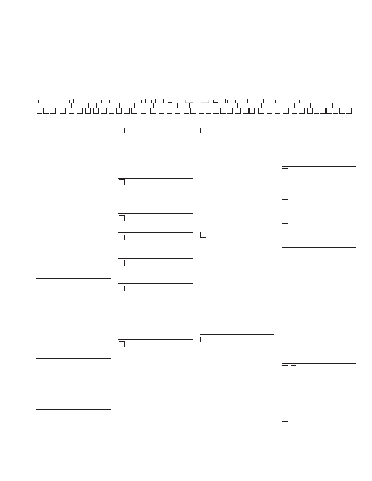
Item 20, 33 -
Rotating Kit
Assembly
Displacement 2.5 cid (41 cc)
A
A
2
3
5148967
Section A-A
4999504-001 1 Rotating Kit Sub-Assembly
1 NSS 1 Cylinder Barrel
2 NSS 1 Internal Retaining Ring
3 NSS 2 Washer
4 NSS 3 Loading Pin
5 NSS 1 Spring
6 NSS 1 Pivot
7 NSS 1 Shoe Retainer
8 NSS 1 Load Pin Keeper
9 NSS 9 Piston Sub-Assembly
* 5991532-001 Rotating Kit S/A set up for Speed Sensor.
NSS - Not Sold Separately
REF PART NO. QTY. DESCRIPTION
Item 20, 33
Rotating Kit Assembly
11
EATON 350 Series Dual Path Mobile Pumps E-PUPI-TS006-E September 2007
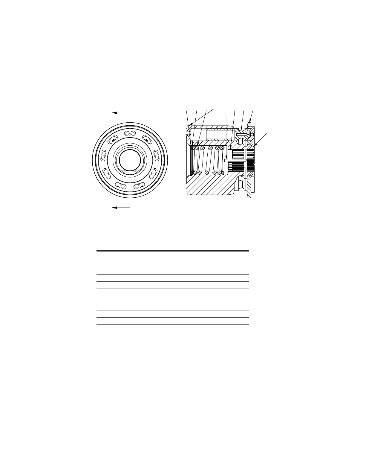
Item 20, 33 -
Rotating Kit
Assembly
Displacement 3.0 cid (49 cc)
A
A
4999502-001 1 Rotating Kit Assembly
1 NSS 1 Cylinder Barrel
2 NSS 1 Internal Retaining Ring
3 NSS 2 Washer
4 NSS 3 Loading Pin
5 NSS 1 Spring
6 NSS 1 Pivot
7 NSS 1 Shoe Retainer
8 NSS 1 Load Pin Keeper
9 NSS 9 Piston Sub-Assembly
* 5991530-001 Rotating Kit S/A set up for Speed Sensor.
NSS - Not Sold Separately
REF PART NO. QTY. DESCRIPTION
Item 20, 33
Rotating Kit Assembly
Section A-A
2
3
5148967

12
EATON 350 Series Dual Path Mobile Pumps E-PUPI-TS006-E September 2007
Item 20, 33 -
Rotating Kit
Assembly
Displacement 3.8 cid (62 cc)
A
A
Section A-A
2
3
514 89
6
7
4999506-001 1 Rotating Kit Sub-Assembly
1 NSS 1 Cylinder Barrel
2 NSS 1 Internal Retaining Ring
3 NSS 2 Washer
4 NSS 3 Loading Pin
5 NSS 1 Spring
6 NSS 1 Pivot
7 NSS 1 Shoe Retainer
8 NSS 1 Load Pin Keeper
9 NSS 9 Piston Sub-Assembly
* 5991720-001 Rotating Kit S/A set up for Speed Sensor.
NSS - Not Sold Separately
REF PART NO. QTY. DESCRIPTION
Item 20, 33
Rotating Kit Assembly
13
EATON 350 Series Dual Path Mobile Pumps E-PUPI-TS006-E September 2007
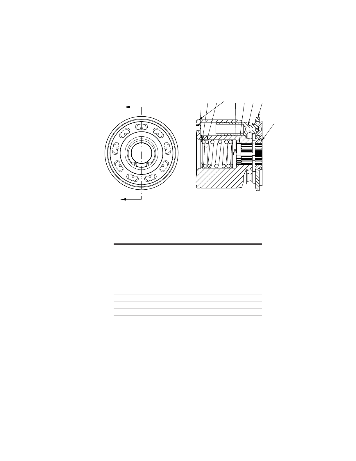
Item 28, 39 -
Drive Shafts
5987541-001 Drive Shaft - Front 4-Bolt C (14T)
5989544-001 Drive Shaft - Front 2-Bolt C (14T)
5991587-001 Drive Shaft - Front 2-Bolt B (Dia 1.00 taper)
5992243-001 Drive Shaft - Front 2-Bolt B (15T)
5992425-001 Drive Shaft - Front 2-Bolt C (19T)
5993096-001 Drive Shaft - Front 2-Bolt B (14T)
PART NO. DESCRIPTION
Item 28
Drive Shaft Front
5987349-001 Drive Shaft - Rear (15T w/Charge Pump)
5987349-002 Drive Shaft - Rear (15T w/Charge Pump)
5989545-001 Drive Shaft - Rear (15T w/o Charge Pump)
5991280-001 Drive Shaft - Rear (13T w/Charge Pump)
5991280-002 Drive Shaft - Rear (13T w/Charge Pump)
5991466-001 Drive Shaft - Rear (13T w/o Charge Pump)
5992244-001 Drive Shaft - Rear (11T w/o Charge Pump)
PART NO. DESCRIPTION
Item 39
Drive Shaft Rear
14
EATON 350 Series Dual Path Mobile Pumps E-PUPI-TS006-E September 2007
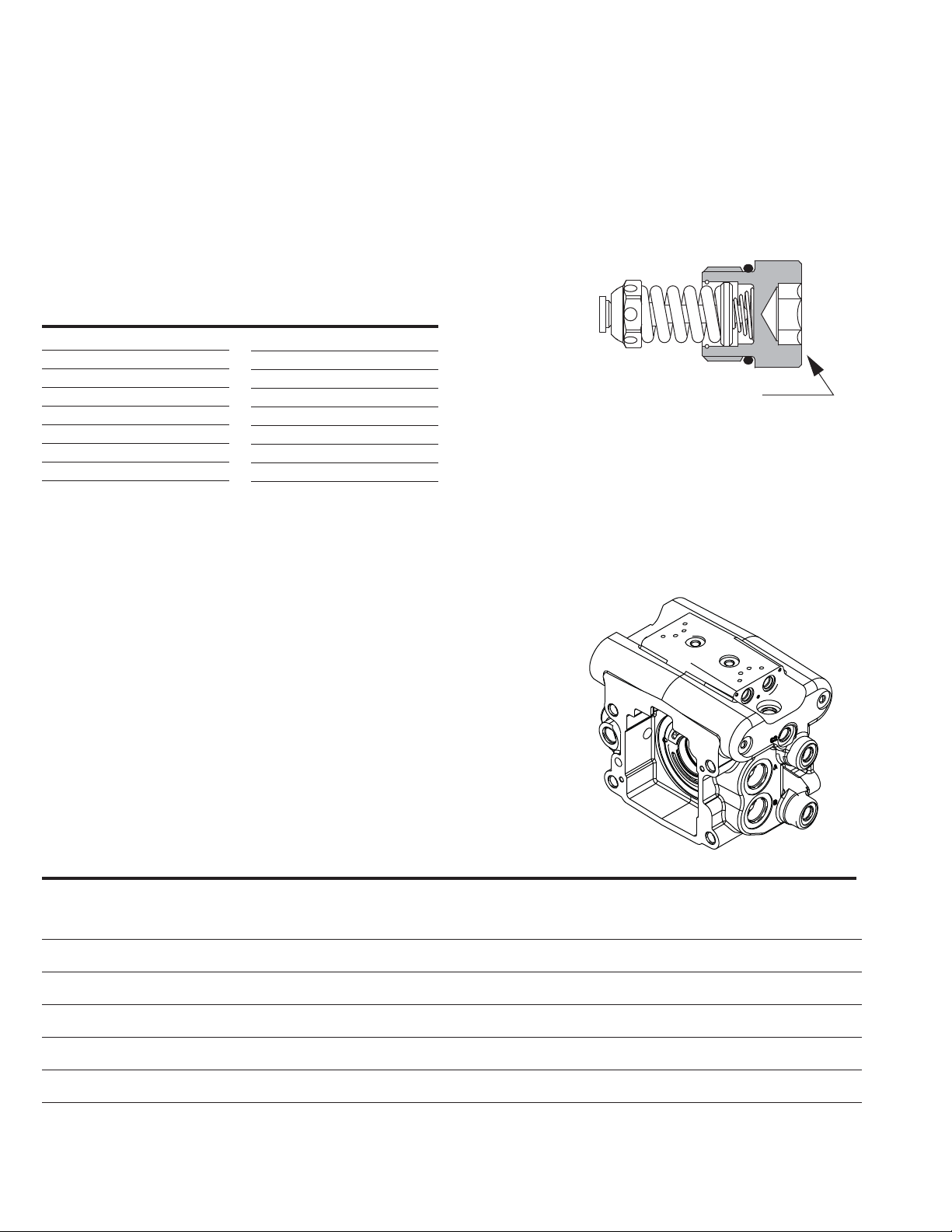
Item 43, 44, 45, 46 -
Relief V alve Sub-Assembly
Item 1 -
Housing
Identification
Dash Number Stamped
here for Valve Pressure
Setting Identification
Example: 500 x 10 = [5000
PSI] 345 bar
Item 43, 44, 45, 46
Relief V alve Sub-Assembly
110700-150 103 [1500]
110700-175 121 [1750]
110700-200 138 [2000]
110700-225 155 [2250]
110700-250 172 [2500]
110700-275 190 [2750]
110700-300 207 [3000]
110700-325 224 [3250]
110700-350 241 [3500]
110700-375 259 [3750]
110700-400 276 [4000]
110700-425 293 [4250]
110700-450 310 [4500]
110700-475 328 [4750]
110700-500 345 [5000]
110700-550 380 [5500]
PART NO. BAR [PSI] PART NO. BAR [PSI]
Item 1
Housing Identification
REF PART NO. QTY. PUMP CONTROLS MAIN PORTS SPECIAL CONTROL OPTIONS
1 5989802-001 thru 1 HA,MA,MB,MC,MD,ME,MF A - 4X 1.3125-12 UN-2B SAE, Same Side, Right
5989802-016 B - 4X 1.3125-12 UN-2B SAE, Same Side, Left
1 5989802-017 thru 1 HA,MA,MB,MC,MD,ME,MF A - 4X 1.3125-12 UN-2B SAE, Same Side, Right Control Pressure EPRV Valve
5989802-032 B - 4X 1.3125-12 UN-2B SAE, Same Side, Left 12 VDC, Deutsch, -4 SAE O-Ring Port
1 5989803-001 thru 1 SA, SB, SC A - 4X 1.3125-12 UN-2B SAE, Same Side, Right
5989803-032 B - 4X 1.3125-12 UN-2B SAE, Same Side, Left
1 5989804-001 thru 1 HA,MA,MB,MC,MD,ME,MF C - 4X 1.3125-12 UN-2B SAE, Opposite Side
5989804-016
1 5989804-017 thru 1 HA,MA,MB,MC,MD,ME,MF C - 4X 1.3125-12 UN-2B SAE, Opposite Side Control Pressure EPRV Valve,
5989804-032 12 VDC, Deutsch, -4 SAE O-Ring Port
1 5989805-001 thru 1 SA, SB, SC C - 4X 1.3125-12 UN-2B SAE, Opposite Side
5989805-032
Part number range is impacted by the addition of special features, special control options, sensor options, and pump controls. Please reference the pump assembly parts list for the exact housing part number.
 Loading...