

Page 1

Service Data
Vickers
®
Piston Pumps
PVH131/141 Variable Displacement
Piston Pump - 11 Design
Revised 05/01/97
M-2209-S
Page 2
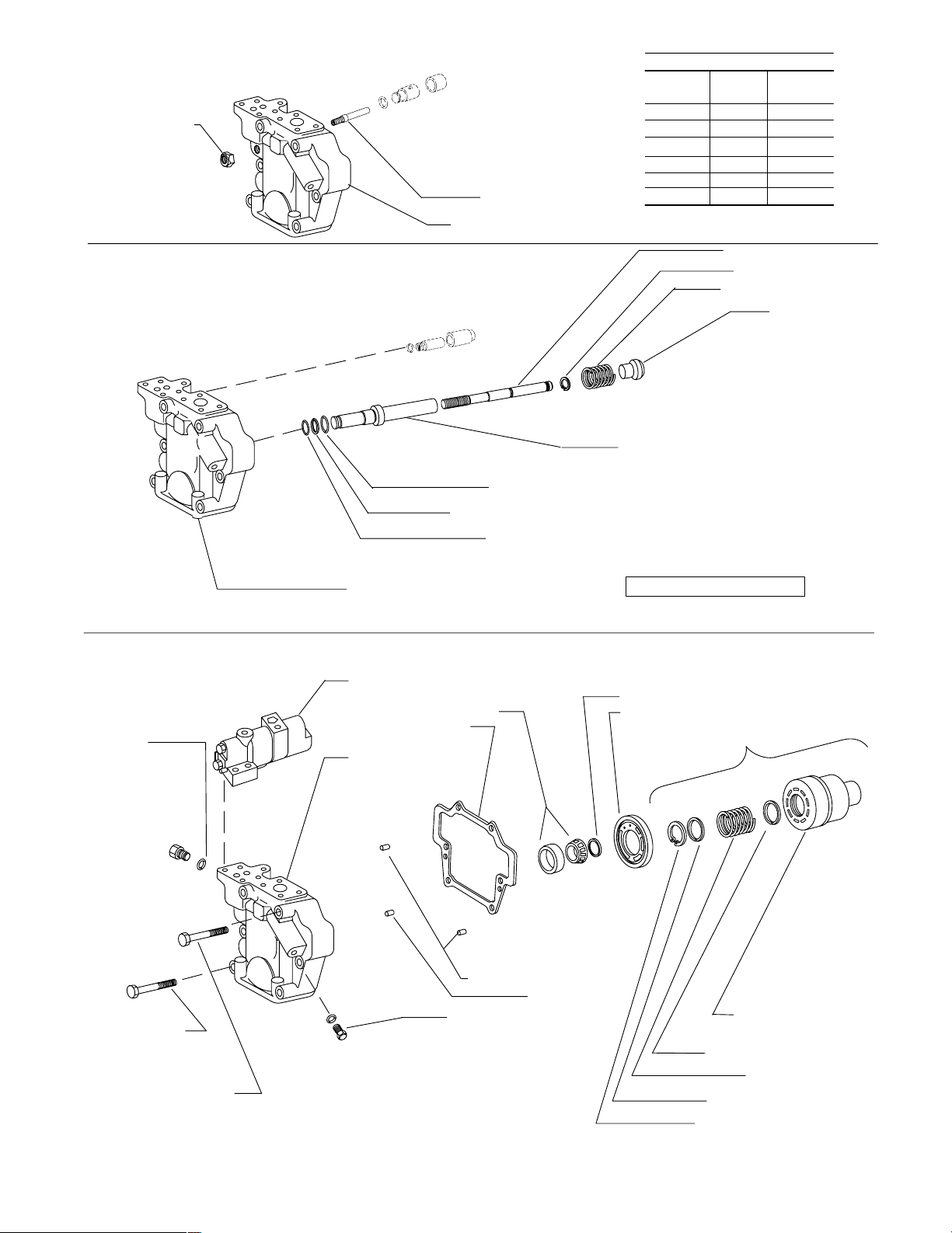
Maximum Adjustable Stop – S Option
913341 Locknut
Torque 25-50 N.m.
(18-37 lb. ft.)
860739 Adj. screw
Valve block (See table)
Valve Block Table
Pump
Type
F–11–C
M–11–C
SF–11–C
SM–11–C
F–11–CT
M–11–CT
RH LH
928637
928638
928624
928625
860852
860853
928687
928688
928673
928674
860861
860862
Torque Limiter – T Option
Standard – C/CM/CMV/CV/IC
396093 O-ring
(2 Req’d)
263500 O-ring
197597 Back-up ring
262359 O-ring
Valve block (See table)
Pump control (see controls pages)
513433 Bearing S/A
526760 Gasket
Valve block
(see table)
928453 Bias piston
928457 Lock ring
526690 Bias spring
928455 Cap
928454 Bias sleeve
Torque 129-142 N.m (95-105 lb. ft)
Grade RC30 compound
Torque control models
02-142690 Shaft spacer kit
Valve plate (see table)
Rotating group kit (See table)
473806 Screw
(4 Req’d)
Torque 103-127 N.m.
(76-94 lb. ft.)
473833 Screw (2 req’d)
Torque 257-315 N.m. (190-232 lb. ft.)
Eaton Hydraulics, Incorporated 2000
All Rights Reserved
471512 Pin (2 Req’d)
248935 Pin
689461 Plug (2 Req’d)
Torque 12.7-13 N.m. (8.9-9.5
lb.ft.)
Cylinder block
(See table)
417667 Spring guide
626111 Spring
581104 Spring guide
135066 Retaining ring
Page 3
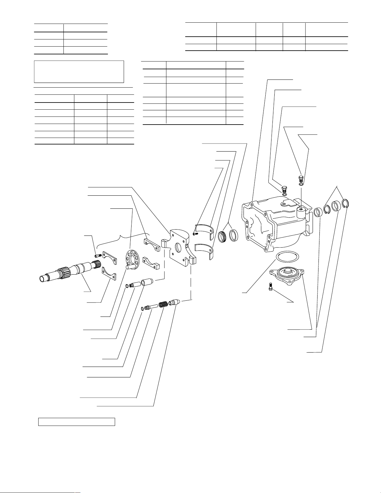
Housing Flange/Seal
692944
876277
864310
-C-*S
-C-*D
-C3-*S
Model
Designation
131 Size
141 Size
Piston & Shoe
S/A (9 req’d)
02-159749
02-306332
Cylinder
Block
680628
928786
Shoe
Cage
683791
928776
Rotating Group
Kit
877419
02-322898
Note
Complete replacement via rotating
group kits is recommended.
V alve Plate Table
Pump Type
131 527164 527163
131QI 864381 876045
131QP 913578 N/A
141 928774 934240
141QI 934242 934243
141QP 934241 N/A
692941 Yoke S/A
526757 Spacer
(2 Req’d)
Shoe cage (See table)
Rotating group kit (See table)
473764 Screw
(4 Req’d)
Torque 31-37 N.m.
(23-27 lb. ft.)
RH LH
Shaft Type Key
876177 3 – Splined thru-drive –
860594 12 – Splined thru-drive –
876176 16 – Straight keyed 633260
thru drive
860802 2 - Splined –
877042 3 - Splined –
860593 12 - Splined –
876175 13 - Straight keyed 140282
388206 Bearing S/A
692948 Saddle bearing
692949 Saddle bearing
690339 Screw (2 Req’d)
Torque 3.6-4.4 N.m.
(2.3-3 lb. ft.)
Housing (See table)
396102 O–Ring
513602 Plug
Torque 97-106 N.m.
(71-78 lb. ft.)
396100 O–Ring
181792 Plug
Torque 75-83 N.m.
(40-43 lb. ft.)
Shaft (See table)
526758 Limiter
(2 Req’d)
Piston & Shoe S/A
(See table)
262355 O–Ring
526754 Control rod
Torque 82-91 N.m. (60-67 lb. ft.)
Grade RC30 compound
526753 Control piston
262355 O–Ring
526752 Bias rod
Torque 82-91 N.m. (60-67 lb. ft.)
Grade RC30 compound
526690 Spring
692152 Bias piston
Non-torque control models
Available in double shaft
seal kit 02–102266
Available in bearing kit 877426
Available in bearing/yoke
kit 02-334838
335659 O–Ring
Available in PVH131 rotating group kit.
Available in PVH141 rotating group kit.
470794 Screw
(3 Req’d)
Torque 7-9 N.m.
(5-6.6 lb. ft.)
692946 Cover
864200 Shaft seal
(2 Req’d if dual seal)
194030 Retaining ring
(2 Req’d if dual seal)
NOTE
Right hand rotation shown. View
is opposite for left hand rotation.
Please refer to Overhaul Manual
M-2210-S.
NOTE
Use shims as required to obtain
0.01–0.10 mm (.0004–.004 in.) axial
shaft end play.
NOTE
For satisfactory service life of these
components in industrial applications,
use full flow filtration to provide fluid
which meets cleanliness code 16/14/12
or cleaner.
Page 4

Load Sensing & Pressure
Compensator Control C(M)*V
857688 Load sense spring
857674 Spring guide
181728 Plug Torque 29-32 N.m. (21-24 lb. ft.)
396096 O-Ring
473765 Screw
(4 Req’d) Torque 31-37 N.m. (23-28 lb. ft.)
857733 CV Body
857673 Load sense spool
857674 Spring guide
857679 Pin spring stop
396100 O-Ring
860748 Plug
Torque 75-83 N.m.
(55-60 lb. ft.)
860747 Nut
(2 Req’d)
Torque 14-20 N.m.
(10-14 lb. ft.)
860749 Plug
Torque 97-106 N.m.
(71-78 lb. ft.)
396102 O-Ring
860750 Adj. screw (2 Req’d)
857734 Spring guide
857681 Control spring
627391 Plug
(2 Req’d)
Torque 29-32 N.m.
(21-24 lb. ft.)
396096 O-Ring
(2 Req’d)
857672 Pressure limiter spool
177969 O-Ring (3 Req’d)
Pressure Compensator Control C & CM
Control spring (See table)
857734 Spring guide (2 Req’d)
857722 Body
473765 Screw (4 Req’d)
Torque 31-37 N.m. (23-28 lb. ft)
857672 Spool
396096 O-Ring
CV
CVB
CMV
Control Kit
02–125161
02–160591
02–306056
Control
Type
All parts shown are included in control kit.
Kit must be set by user to circuit requirements.
Pressure
range
140–280 Bar
35–140 Bar
857681
857675
857734 Spring guide
BodySpring
857733
928442
857733
396102 O-Ring
860750 Adj. screw
Torque 97-106 N.m.
Orifice
Plug
–
433543
–
860749 Plug
(71-78 lb. ft.)
627391 Plug
Torque 29-32 N.m.
(21-24 lb. ft.)
177969 O-Ring (3 Req’d)
860747 Nut
Torque 14-20 N.m.
(10-14 lb. ft.)
Control Type
C
CM
All parts shown are included in control kit.
Pressures must be set by user to circuit requirements.
Control Kit
02–125160
02–125162
Pressure range
70-250 Bar
40-130 Bar
Spring
857681
857675
Page 5

Industrial Control (IC)
473769 Screw (2 Req’d)
Torque 31-37 N.m. (23-28 lb. ft.)
407533 Plug
Torque 12.1-12.4 N.m. (8.9-9.1 lb. ft.)
396093 O-Ring
396092 O-Ring (3 Req’d)
398071 Plug (3 Req’d)
Torque 9.8-10.2 N.m. (7.2-7.5 lb. ft.)
Body (see table)
626157 Spring
860606 Spring guide (2 Req’d)
396100 O-Ring
860747 Nut
Torque 14-20 N.m.
(10-14 lb. ft.)
860750 Adj. screw
860748 Plug
Torque 75-83 N.m. (55-60 lb. ft.)
Torque Limiter – T Option
860749 Plug
Torque 75-83 N.m
(102-112 lb. ft.)
860750 Adjusting Screw
860747 Nut
Torque 8-10 N.m
(11-14 lb. ft.)
1649 Ball
471627 Pin
937272 Check valve
Torque 1.7-2.3 N.m
(2.3-3.1 lb. ft.)
217669 O-ring
177969 O-ring
(2 req’d)
Control Kit Threads Body
02–151906 inch 883386
02–151907 metric 860628
All parts shown are included in control
kit. Pressures must be set by user to circuit
requirements.
928388 Guide
857675 Spring
857734 Guide
263069 O-ring
473765 Screw
(2 Req’d) Torque 31-37 N.m. (23-28 lb. ft.)
113000 Plug
Torque 5.1-5.9 N.m. (3.7-4.4 lb. ft.)
860566 Orifice plug
Torque 1.7-2.3 N.m.
(1.2-1.7 lb. ft.)
396096 O-Ring
181728 Plug
Torque 29-32 N.m.
(21-24 lb. ft.)
627391 Plug
Torque 29-32 N.m.
(21-24 lb. ft.)
396096 O-Ring
939816 Spool
177969 O-Ring
(2 req’d)
216630 O-Ring
NOTE
IC kits pre-set to 20-30 bar differential
pressure with all orifices/plugs in
place. Reference Vickers Overhaul
Manual M-2210-S for proper orifice/
plug configuration in various circuits
prior to control installation.
913453 Guide
473773 Screw (4 req’d)
Torque to 31-37 N.m
(42-50 lb. ft.)
197594 Back-up ring
262356 O-ring
860655 Plug Torque 75-83
N.m (102-112 lb. ft.)
248823 Pin
186580 Plug
Torque 54-59 N.m
(73-80 lb. ft.)
263497 O-ring
113000 Plug
Torque 15-17 N.m
(20-23 lb. ft.)
913454 Spool
860653 Body
177969 O-ring (5 req’d)
577639 Sleeve
262499 O-ring
Model designation Control Kit
C**T**-31
C**T**S-31
02–314944
02–335254
248845 Pin
932716 Retainer Ring
(Screw into bottom of thread)
932716Connector
Torque 54-59 N.m
(73-80 lb. ft.)
263497 O-ring
Torque summation parts
Page 6

*A* Thru–drive
Valve block
(See table)
Thru–drive
Adapter location
(See table)
473806 Screw (4 Req’d)
Torque 83-102 N.m. (61-75 lb. ft.)
‘‘A’’ Thru–drive
473833 Screw (2 req’d)
Torque 257-315 N.m. (189-232 lb. ft.)
473800 Screw (2 Req’d, SAE
“B”/“C” pad) Torque 103-127 N.m.
(76-94 lb. ft.)
Coupling
(See table)
Rear
Pump
O-Ring
(See table)
Model designation
LAF–11–C*
LAM–11–C*
RAF–11–C*
RAM–11–C*
LAF–11–CT
LAM–11–CT
RAF–11–CT
RAM–11–CT
‘‘B’’ & ‘‘C’’ Thru–drive Adapter
Model Designation
*–*BF–11–*
*–*BM–11–*
*–*CF–11–*
*–*CM–11–*
Notes:
1.‘‘F’’ type equal SAE threads
2. ‘‘M’’ type equal metric threads
3. ‘‘B’’ and ‘‘C’’ thru-drives created from
‘‘A’’ thru-drive pump with ‘‘B’’ or ‘‘C’’
thru-drive adapter kit installed.
4. All screws/O-rings are included with
each ‘‘kit’’ to convert from ‘‘A’’ to
‘‘B’’ or ‘‘C’’ thru-drive unit.
Valve block
w/ SAE ‘‘A’’ Pad
928713
928714
928736
928737
860843
860844
860834
860835
Adapter
Pad Kit
876390
876394
876389
876392
Adapter
Flange
526670
876393
692934
876391
O-Ring
576601 877039
Coupling
Type
O-Ring CouplingTypes
401525
353264
877040 SAE-B 13 tooth
877044 SAE-BB 15 tooth
877045 SAE-C 14 tooth
877046 SAE-CC 17 tooth
SAE–A, 2–Bolt Cover
Plate 939790
(Fits –031 Suffix Pumps)
*AF Units use Screw 170177
(2 req’d)
**AM Units use Screw 470837
(2 req’d)
Page 7

Typical Cross Section
Control Piston
Control Rod
Valve Block
Port #1
Position outer shaft
seal facing shaft end
Position inner shaft
seal facing bearing
Pump Startup
Make sure the reservoir and circuit are
clean and free of dirt and debris prior
to filling with hydraulic fluid.
Fill the reservoir with filtered oil to a
level sufficient to prevent vortexing at
suction connection to pump inlet. It is
good practice to clean the system by
flushing and filtering using an external
slave pump.
Before starting the pump, fill with fluid
through one of the ports. This is par-
ticularly important if the pump is above
the fluid level of the reservoir.
Note
Parts are shown as installed for right
hand rotation. For left hand rotation,
install control rod and control piston
in valve block port #2. Install bias
rod, bias piston and spring in valve
block port #2.
When initially starting the pump, remove
all trapped air from the system. This can
be accomplished by loosening the pump
outlet fittings or connections before
starting the pump, or by using an air
bleed valve. All inlet connections must
be tight to prevent air leaks.
Once the pump is started, it should
prime within a few seconds. If the pump
does not prime, check to make sure that
there are no air leaks in the inlet line
and connections. Also check to make
sure that trapped air can escape at the
pump outlet.
Valve Block
Port #2
Bias Rod
Bias Piston
Spring
After the pump is primed, tighten the
loose outlet connections, then operate
for five to ten minutes (unloaded) to remove all trapped air from the circuit. If
reservoir has a sight gage, make sure
the fluid is clear—not milky.
Add fluid to the reservoir up to the proper fill level.
Page 8

Model Code
1 2
1
Piston pump, variable
3 4 5876
displacement
2
Maximum geometric
displacement
131 - 131.1 cm
141 -141.6 cm
3
Application style
3
/r (8.0 in3/r)
3
/r (8.64 in3/r)
Blank - Mobile application (rated speed
& 250/280 bar (3600-4000 psi)
pressures)
QI - Quiet industrial application (1500 -
1800 rpm & 250/280 bar
(3600-4000 psi) pressures)
QP - Quiet power unit application (1800
rpm & 140 bar (2000 psi) max.
pressures – R.H. rotation only)
Mounting flange, prime
4
mover end
C - SAE “C” 4–bolt type (SAE
J744-127-4 )
C3 - Optional 4-bolt SAE-C pilot for
vertical pump mounting
5
Shaft rotation, viewed at prime
mover end
R - Right hand, clockwise
L - Left hand, counterclockwise
6
Configuration
Blank - Non-thru-drive (single pump)
A - SAE-A thru-drive pump, standard
(SAE J744-82-2)
B - SAE-B thru-drive pump, optional
(SAE J744-101-2/4)
C - SAE-C thru-drive pump, optional
(SAE J744-127-2/4)
S - Adjustable maximum volume
stop (‘‘S’’ option not available on
thru-drive and torque control pump
models.)
7
Main ports
9 10
11 12 13 14 15 16 17
F - SAE 4-bolt flange ports (standard)
M - SAE 4-bolt pads with metric
mounting bolt threads
8
Shaft-end type, at prime mover end
2 - SAE-C 14 tooth spline
3 - SAE-CC 17 tooth spline
12 - SAE-D 13 tooth spline
13 - SAE-CC straight keyed
16 - SAE-D straight keyed
9
Shaft seal, prime mover end
S - Single, one-way
D - Double, two-way
10
Pump design number
11 - (Subject to change. Installation
dimensions unaltered for design
numbers 10 to 19 inclusive. )
11
Pressure control type
C - Compensator, 140-280 bar
(2000-4000 psi)
CM - Compensator, 35-140 bar
(500-2000 psi)
IC - CETOP 3 interface compensator,
20 bar factory ‘‘differential’’ pressure
setting (QI and QP models only)
12
Factory compensator pressure
setting
Blank - Leave blank for ‘‘IC’’ controls only
7 - 70 bar (1015 psi) normal ‘‘CM7’’
setting (all pump sizes)
23 - 230 bar (3335 psi) normal ‘‘C23’’
setting (63, 81, 106, 141 models)
25 - 250 bar (3625 psi) normal ‘‘C25’’
setting (57, 74, 98, 131 models)
13
Optional pressure control
functions
Blank - Leave blank for basic compensator
controls of IC models.
V - Load sensing, 20 bar (290 psi)
factory ‘‘differential’’ pressure setting
T - Torque limiting control (Used with
sections and .
14
15
VT - Load sensing with torque limiting
VB - Load sensing with internal bleed
down (0.15” dia. orifice)
VBT-Load sensing with internal bleed
down and torque limiting
Torque limiting control pressure
14
setting
Blank - Leave blank if no torque limiting
control is used
4 - Standard minimum 40 bar setting of
‘‘T’’ torque control option
Torque limiting control
15
summation
Blank - Standard torque control
S - Optional torque control with
summation feature
16
Control design number
31 - All control options
Special feature suffix
17
031- Mounting with SAE-A, 2-bolt cover
plate
Printed in U.S.A.
Page 9

Eaton Hydraulics
15151 Highway 5
Eden Prairie, MN 55344
Telephone: 612 937-7254
Fax: 612 937-7130
www.eatonhydraulics.com
46 New Lane, Havant
Hampshire PO9 2NB
England
Telephone: (44) 170-548-6451
Fax: (44) 170-548-7110
Form No. 00-000 Copyright Eaton Corporation, 0000
All rights reserved.
Printed in U.S.A
 Loading...