

Page 1
Disconnect Switches
Product Guide
Rotary Switches
Non-fused
Fused
Enclosed Rotary
Operating Mechanisms
Accessories
Page 2

December 2004
Disconnect Switches
Contents
Description Page
Rotary Disconnect Switches C362/C363
Product Description. . . . . . . . . . . . . . . . . . . . . . . . . . . . . . . . . . . . . . . . . . . . 2
Features, Benefits and Functions . . . . . . . . . . . . . . . . . . . . . . . . . . . . . . . . . 2
Standards and Certifications . . . . . . . . . . . . . . . . . . . . . . . . . . . . . . . . . . . . 2
Options and Accessories . . . . . . . . . . . . . . . . . . . . . . . . . . . . . . . . . . . . . . . 2
Product Selection
C362 – Non-fused Switches R, W, C, V & S Frames
C363 – Fusible Switches, C,V, F Frame Switches. . . . . . . . . . . . . . . . . . 4
Handles and Shafts . . . . . . . . . . . . . . . . . . . . . . . . . . . . . . . . . . . . . . . . . 5, 6
Accessories . . . . . . . . . . . . . . . . . . . . . . . . . . . . . . . . . . . . . . . . . . . . . . . . 7
Technical Data and Specifications R, W Frame. . . . . . . . . . . . . . . . . . . . . . 8
C-Frame . . . . . . . . . . . . . . . . . . . . . . . . . . . . . . . . . . . . . . . . . . . . . . . . . . . . . 9
V-Frame . . . . . . . . . . . . . . . . . . . . . . . . . . . . . . . . . . . . . . . . . . . . . . . . . . . . . 10 - 12
S-Frame . . . . . . . . . . . . . . . . . . . . . . . . . . . . . . . . . . . . . . . . . . . . . . . . . . . . . 13
F-Frame . . . . . . . . . . . . . . . . . . . . . . . . . . . . . . . . . . . . . . . . . . . . . . . . . . . . . 14
Handles. . . . . . . . . . . . . . . . . . . . . . . . . . . . . . . . . . . . . . . . . . . . . . . . . . . . . . 15
Technical Characteristics . . . . . . . . . . . . . . . . . . . . . . . . . . . . . . . . . . . . . . . 16 , 17
Enclosed Rotary Disconnect Switches. . . . . . . . . . . . . . . . . . . . . . . . . . . . . . . 18 - 23
Product Selection . . . . . . . . . . . . . . . . . . . . . . . . . . . . . . . . . . . . . . . . . . . . . 18
Dimensional Drawings . . . . . . . . . . . . . . . . . . . . . . . . . . . . . . . . . . . . . . . . . 19 - 23
C361/C371 Operating Mechanisms . . . . . . . . . . . . . . . . . . . . . . . . . . . . . . . . . 24 - 29
C361 Variable Depth Disconnects . . . . . . . . . . . . . . . . . . . . . . . . . . . . . . . . 24 - 25
C361 Fixed Depth Disconnects . . . . . . . . . . . . . . . . . . . . . . . . . . . . . . . . . . . 26
C361 Accessories. . . . . . . . . . . . . . . . . . . . . . . . . . . . . . . . . . . . . . . . . . . . . . 27
C371 Fixed/Variable Depth Circuit Breakers . . . . . . . . . . . . . . . . . . . . . . . . 28 - 29
. . . . . . . . . . . . . . . 4
1
Manual Motor
Disconnect Switches
For more information visit us at: www.eatonelectrical.ca
Page 3

2
Rotary Disconnect Switches
Product Description
Product Description
Non-fused
R & W frame, 30A – 80A, non-fusible
■
600V AC , suitable for use in
equipment or machinery as a motor
disconnect.
Manual motor controller suitable for
■
motor disconnect,
Amp rated, load break rated, meeting
requirements of CSA C22.2 No 14 CEC
rule 28-602 (3) (b) and UL508 “suitable
for motor disconnect.” 10 kVA short
circuit rating when used in conjunction
with Class J fusing.
C, V, & S Frame, 30A - 1200A,
■
non-fusible, 600V AC, rated
250 V DC inclusive to 600A. Suitable
for use as motor or industrial control panel disconnects, horsepower
and Amp rated, load break rated,
meeting requirements of CSA C22.2
No 4 and UL98.
Fusible
■
30A - 800A fusible 600V AC,
C, V & F Frame , rated 250 V DC
inclusive to 400A. Suitable for use
as motor or industrial control panel
disconnect, suitable for use as a
service entrance disconnect, horsepower and Amp rated, load break
rated, meeting requirements of CSA
C22.2 No 4 and UL98.
horsepower and
Features, Benefits and Functions
■
Fusible and non-fusible
■
Rotary or toggle operation
(non-fused)
Motor disconnects available
■
approved to CEC rule
28-602(3)(b)
Base mounting or DIN rail mounting
■
Compact design to minimize panel
■
space requirements
■
Pistol type or selector type handles
for through-the-door operation.
Toggle type handle for internal
■
panel mounting
■
Variable depth – complete range of
shafts that can be cut for specific
enclosure depths
Clear ON and OFF indication.
■
Padlockable in the OFF position with
■
up to three padlocks.
■
Interlocked, defeatable handle available. Allows access by authorized
personnel in the ON position.
■
ON/OFF/TEST (3 position) handles
allow testing of the control circuit
auxiliaries without switching the
main contacts.
Optional N/O, N/C auxiliary contacts
■
available
Visible blade indication up to 200A
■
(non-fused C & V frames)
December 2004
■
Line side shrouds standard on all
ratings for C, S, V & F frames
Load side finger shrouds standard
■
on non-fusible 30-100A C & V frame
and 30-60A fusible.
Optional shrouds available for
■
higher ratings of V, S & F frame
■
Terminal lugs standard for C & V
frame 30-100A non-fused and
30-60A fusible.
Standards and Certifications
R- W-Frames
UL 508
■
CSA C22.2 No 14
■
CEC rule 28-602(3)(b)
IEC 60-947-3
■
C-, V-, S-, F-Frames
■
UL 98
CSA C22.2 # 4
■
■
IEC 60-947-3
CE
■
Options and Accessories
Neutral modules.
■
■
Auxiliary contacts.
4th pole modules.
■
■
Protective earth modules.
C-Frame
Non-Fusible
Non-Fusible
NOTE: Photo does not represent proportional sizing between frame types
R-Frame
C-Frame
Fusible
W-Frame
Non-Fusible
For more information visit us at: www.eatonelectrical.ca
V-Frame
Fusible
S-Frame
Non-Fusible
V-Frame
Non-Fusible
F-Frame
Fusible
Page 4
December 2004
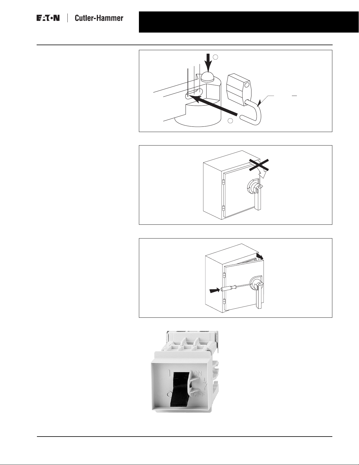
Padlocking
Handles can be padlocked in the OFF
position with up to three padlocks.
For safety reasons, the door cannot be
opened when the handle is padlocked.
Door Interlock in ON Position
The handles allow opening of the door
in the OFF position only. In the ON
position, the door cannot be opened.
This interlocking can however be
bypassed by authorized personnel
(defeater option on handle) for maintenance, testing or commissioning.
Rotary Disconnect Switches
Product Description
1
3x
2x
1x
2
Figure 1. Padlocking Capability (Type G Pistol Handle is Shown)
I-ON
OFF
5
maxi. ø in / 8 mm
16
3
Defeater
The defeat function allows qualified
personnel to bypass the door interlock
when the switch is in the ON position
by means of a tool.
This exclusive design is also available
in a 4 and 4X rating.
Toggle Option
Available for internal panel mounting.
Figure 2. Door Interlocking
ON
OFF
Figure 3. Interlocking Defeater
Toggle Operated Switch
(Shown with Optional Toggle Cover Plate
CWP3)
For more information visit us at: www.eatonelectrical.ca
Page 5

4
Rotary Disconnect Switches
Product Selection
Product Selection — Switches
Catalogue Ordering Information
When ordering specify:
Catalogue number of switch.
■
Catalogue number of operating handle. Pages 5,6.
■
Catalogue number of required shaft. Pages 5,6.
■
Catalogue number of (optional) accessories. Page 7.
■
■
For dimensional data. Pages 8-15.
For technical data. Pages 16, 17.
■
Table 1.
Non-Fusible Switches
15
20
30
40
15
20
30
40
30
60
125
250
400
500
500
500
20
25
40
50
20
25
40
50
50
75
150
350
350
500
500
500
Catalogue
Number
C362NR30MD
C362NR40MD
C362NW60MD
C362NW80MD
C362TR30MD
C362TR40MD
C362TW60MD
C362TW80MD
C362UC30
C362UV60
C362UV100
C362UV200
C362US400
C362US600
C362US800
C362US1000
C362US1200
Ampere
Rating
Maximum 3-Phase
Horsepower Rating
240V 480V 600V
DIN Rail / Base Mounted Rotary Switch R-, W-Frame with Brass Collar
30
40
60
80
7.5
10
15
20
DIN Rail / Base Mounted Toggle Switch R-, W-Frame
30
40
60
80
7.5
10
15
20
DIN Rail / Base Mounted Rotary Switch C-Frame
30 7.5 15 20
Base Mounted Rotary Switch V-Frame
60
100
200
15
30
60
Base Mounted Rotary Switch S-Frame
400
600
800
1000
1200
125
200
250
250
250
December 2004
Table 2.
Fusible Switches
Ampere
Rating
Fuse
Maximum 3-Phase
Type
Horsepower Rating
600V
240V 480V 600V
Catalogue
Number
DIN Rail / Base Mounted Fusible Switch C-Frame
30
30
CCJ 7.5
7.5
15
15
20
20
C363UC30CT (CC)
C363UC30JT (J)
Base Mounted Fusible Switch V-Frame
30
30
60
100
200
400
30
30
60
100
200
400
C
7.5
J
7.5
J
15
J
30
J
60
J
125
C
7.5
J
7.5
J
15
J
30
J
60
J
125
15
15
30
60
125
250
15
15
30
60
125
250
20
20
50
75
150
350
20
20
50
75
150
350
C363UV30C
C363UV30J
C363UV60J
C363UV100J
C363UV200J
C363UV400J
C363UV30CT
C363UV30JT
C363UV60JT
C363UV100JT
C363UV200JT
C363UV400JT
Base Mounted Fusible Switch F-Frame
600
800
JL250
250
500
500
500
500
C363UF600J
C363UF800L
Note: “T” suffix denotes test position is provided. Test handle is
required for test function.
Note: Suffix “MD” indicates Manual Motor Controller suitable for
Motor Disconnect meeting requirements of CSA C22.2 No.14
CEC rule 28-602(3)(b) and UL508 “suitable for motor disconnects”.
For additional HP ratings refer to pages 16 and 17.
For more information visit us at: www.eatonelectrical.ca
Page 6

Rotary Disconnect Switches
December 2004
Product Selection – Handles and Shafts
Fusible/Non-Fusible Accessories
Product Selection — Handles and Shafts
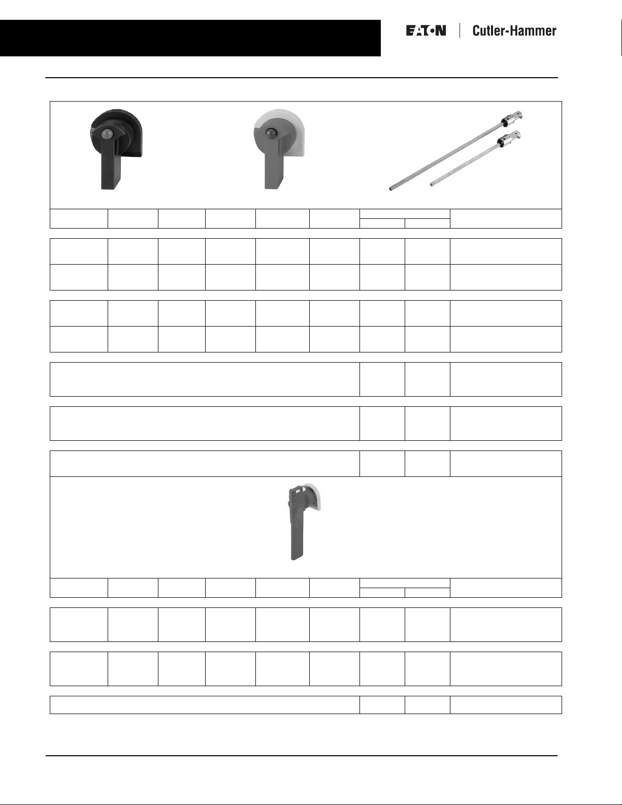
Table 5. Handles and Shafts
Black Selector Handle
NEMA
Rating
Defeatable Padlockable Color Operation IEC Type Dimensions Catalogue
Selector Handle for Type CSSA __ Shaft and R- and W-Frames or CSCSA __ Shaft and C-Frames
1
1, 3R, 12
1, 3R, 12
No
No
No
No
Ye s
Ye s
Rotary Switch Selector Shaft 5 x 5 mm (For Selector Handle and R- and W-Frames)
Rotary Switch Selector Shaft 5 x 5 mm (For Selector Handle and C-Frames)
Red/Yellow Selector Handle
Black
Red/Yellow
Black
ON/OFF
ON/OFF, I/O
ON/OFF, I/O
IP54
IP65
IP65
Inches mm
—
—
2.2
4.3
5.9
7.1
7.9
11.8
4.7
7.9
11.8
15.7
—
—
—
55
110
150
180
200
305
120
200
300
400
5
Selector Shafts
Number
CSBR5
CSYR6
CSBR6
CSSA055
CSSA110
CSSA150
CSSA180
CSSA200
CSSA300
CSCSA120
CSCSA200
CSCSA320
CSCSA400
Black Pistol Handle (Type D)
NEMA
Rating
Defeatable Padlockable Color Operation IEC Type Dimensions Catalogue
Red/Yellow Pistol Handle (Type D)
Pistol Handle Type D (For use with CPDSA & CPDCSA Shafts for R- and W-Frames and C-Frame.)
1, 3R, 12
1, 3R, 12
1, 3R, 12
1, 3R, 12
No
No
Ye s
Ye s
Ye s
Ye s
Ye s
Ye s
Black
Red/Yellow
Black
Red/Yellow
ON/OFF, I/O
ON/OFF, I/O
ON/OFF, I/O
ON/OFF, I/O
IP54
IP54
IP54
IP54
Type D Shafts 5 x 5 mm (For use with Type D Pistol Handles and R- and W-Frames)
Type D Shafts 5 x 5 mm (For use with Type D Pistol Handles and C-Frames)
Direct Handle R-, W-Frames (For Direct Mounting — No Separate Shaft Required)
1, 3R, 12
1, 3R, 12
1, 3R, 12
Please refer to Page 15 .
No
No
No
Ye s
Ye s
Ye s
Black
Black
Black
ON/OFF
ON/OFF
ON/OFF
IP54
IP54
IP54
For more information visit us at: www.eatonelectrical.ca
Inches mm
—
—
—
4.7
7.9
12.6
15.7
4.7
7.9
12.6
15.7
—
—
—
—
—
—
120
200
320
400
120
200
320
400
—
—
—
Type D Pistol Shafts
Number
CPBR5N
CPYR5N
CPBR5D
CPYR5D
CPDSA120
CPDSA200
CPDSA320
CPDSA400
CPDCSA120
CPDCSA200
CPDCSA320
CPDCSA400
CDRR3
CDRW3
CDRR4
Page 7
6
Rotary Disconnect Switches
Product Selection – Handles and Shafts
Table 5. Handles and Shafts (Continued)
Black Pistol Handle (Type G) Red/Yellow Pistol Handle (Type G) Type G Pistol Shafts
NEMA
Rating
Pistol Handle Type G (For use with R-, W- and C-Frames with 5 x 5 shaft and V-Frame below 100A with 10 x 10 shaft)
1, 3R, 12
1, 3R, 12
1, 3R, 12, 4, 4X
1, 3R, 12, 4, 4X
1, 3R, 12, 4, 4X
1, 3R, 12, 4, 4X
Long Pistol Handle Type GL (For use with V-Frame 100A and above with 10 x 10 shaft)
1, 3R, 12
1, 3R, 12
1, 3R, 12, 4, 4X
1, 3R, 12, 4, 4X
1, 3R, 12
1, 3R, 12
Type G Shafts 5 x 5 mm (For use with Type G Pistol Handle and R- and W-Frames)
Type G Shafts 5 x 5 mm (For use with Type G Pistol Handle and C-Frames)
Type G Shafts 10 x 10 mm (For use with Type G and GL Pistol Handles and V-Frames)
Defeatable Padlockable Color Operation IEC Type Dimensions Catalogue
Ye s
Ye s
Ye s
Ye s
Ye s
Ye s
Ye s
Ye s
Ye s
Ye s
Ye s
Ye s
Ye s
Ye s
Ye s
Ye s
Ye s
Ye s
Ye s
Ye s
Ye s
Ye s
Ye s
Ye s
Black
Red/Yellow
Black
Red/YellowBlack
Red/Yellow
Black
Red/Yellow
Black
Red/Yellow
Black
Red/Yellow
ON/OFF, I/O
ON/OFF, I/O
ON/OFF, I/O
ON/OFF, I/O
TEST/ON/OFF
TEST/ON/OFF
ON/OFF, I/O
ON/OFF, I/O
ON/OFF, I/O
ON/OFF, I/O
TEST/ON/OFF
TEST/ON/OFF
IP54
IP54
IP65
IP65
IP65
IP65
IP54
IP54
IP65
IP65
IP65
IP65
Inches mm
4.7
7.9
12.6
15.7
4.7
7.9
12.6
15.7
7.9
12.6
15.7
120
200
320
400
120
200
320
400
200
320
400
December 2004
Number
CPBR5
CPYR5
CPBW6
CPYW6
CPBW6T
CPYW6T
CPBVR5
CPYVR5
CPBVW6
CPYVW6
CPBVW6T
CPYVW6T
CPGSA120
CPGSA200
CPGSA320
CPGSA400
CPGCSA120
CPGCSA200
CPGCSA320
CPGCSA400
CPGSB200
CPGSB320
CPGSB400
Pistol Handle (Type H)
NEMA
Defeatable Padlockable Color Operation IEC Type Dimensions Catalogue
Rating
Pistol Handle Type H (For use with S-Frames with 15 x 15 shaft)
1, 3R, 4, 4X, 12
1, 3R, 4, 4X, 12
1, 3R, 4, 4X, 12
1, 3R, 4, 4X, 12
Ye s
Ye s
No
No
Ye s
Ye s
Ye s
Ye s
Black
Red/Yellow
Black
Red/Yellow
ON/OFF, I/O
ON/OFF, I/O
ON/OFF, I/O
ON/OFF, I/O
Pistol Handle Type H (For use with F-Frames with 15 x 15 shaft)
1, 3R, 4, 4X, 12
1, 3R, 4, 4X, 12
1, 3R, 4, 4X, 12
1, 3R, 4, 4X, 12
Ye s
Ye s
No
No
Ye s
Ye s
Ye s
Ye s
Black
Red/Yellow
Black
Red/Yellow
ON/OFF, I/O
ON/OFF, I/O
ON/OFF, I/O
ON/OFF, I/O
Type H Shafts 15 x 15 mm (For use with Type H Pistol Handles and S- and F-Frames)
Please refer to Page 15.
For more information visit us at: www.eatonelectrical.ca
IP65
IP65
IP65
IP65
IP65
IP65
IP65
IP65
Inches mm
—
—
—
—
—
—
7.9
15.7
—
—
—
—
—
—
—
—
200
400
Number
CPBSW6D
CPYSW6D
CPBSW6N
CPYSW6N
CPBFW6D
CPYFW6D
CPBFW6N
CPYFW6N
CPHSC200
CPHSC400
Page 8

Rotary Disconnect Switches
December 2004
Product Selection — Accessories
Table 3. Accessories — R, W-Frames
Description Catalogue
Toggle Cover Plates For use with C362TR30MD & 40MD
Auxiliary Contacts
Kit (Holder and
Contact)
Auxiliary Contacts
(Additional Contacts)
Extension Support C362SS1
Replacement Brass Collar R and W-Frames CRC
Door Mounting Kit R and W-Frames
Rotary Switches
The mechanism is reversed on these contacts.
For use with C362TW60MD & 80MD
1NO for R-Frame (30 & 40 Amps)
1NO for W-Frame (60 & 80 Amps)
1NO - for R, W-Frame
1NC - for R, W-Frame
Fusible/Non-Fusible – Accessories
Number
CRP3
CWP3
CRAC3
CWAC3
CRAB
CRAA
CTRFC
7
Table 4. Accessories — C, S, V, F-Frames
Description Catalogue
Auxiliary Contact
Holders
Auxiliary Contacts 1 NO, Type U aux. contact for
C-Frame (for 5-8)
V-Frame (for 1-8)
S-Frame (for 1-4)
C, V, S Frames
1 NC, Type U aux. contact for
C, V, S Frames
1 NO/NC, Type S aux. contact, for
30A-400A V-Frames
2 NO/NC, Type S aux. contact, for
30A-400A V-Frames
1 NO/NC, Type ST aux. contact for
Fusible, 30A-400A V-Frame w/Test
2 NO/NC, Type ST aux. contact for
Fusible, 30A-400A V-Frame w/Test
1 NO/NC, Type MS aux. contact, for
Fusible 600A & 800A F-Frame
2 NO/NC, Type MS aux. contact, for
Fusible 600A & 800A F-Frame
Load-Side
Terminal Shrouds for
Non-Fusible
V- and S-Frames
3-Pole, V-Frame (200A) CUV200T
3-Pole, for Non-Fusible
S-Frame (400 - 600A)
3-Pole, for Non-Fusible
S-Frame (800 - 1200A)
Load-Side
Terminal Shrouds for
Fusible V- and
F-Frames
3-Pole, for Fusible V-Frame (100A)
3-Pole, V-Frame (200A)
3-Pole, for Fusible V-Frame (400A)
3-Pole, for Fusible F-Frame
(600 & 800A)
Shorting Links
for 3 Poles
Fusible, V- and
F-Frames
V-Frame (60A)
V-Frame (100A)
V-Frame (200A)
V-Frame (400A)
F-Frame (600 & 800A)
Terminal Lugs
for Non-Fusible and
Fusible V-, S- and
F-Frames, for line or
load side
1 Wire/lug, Wire Size #12-2/0, for
Fusible V-Frame (100A)
1 Wire/lug, Wire Size #6-3/0, for
V-Frame (200A)
2 Wires/lug, Wire Size #2-600,MCM
for V, S- & F-Frames (400 & 600A)
3 Wires/lug, Wire Size #2-600, MCM
for S-& F-Frames (800-1000A)
2 Wires/lug, Wire Size# 2-600, MCM
S-Frame (1200A)
C-Frames (standard product) hold 1-4 Auxiliary Contacts without
additional holder.
Line-side terminal shrouds provided as standard on all ratings. Load-side
terminal shrouds standard on non-fused C and V-Frames up through
100A.
Line-side terminal shrouds provided as standard on all ratings. Load-side
terminal shrouds standard on fusible switches up through 60A.
Kit of 3.
Terminal lugs provided as standard on Non-Fusible up through 100A and
Fusible up through 60A.
Kit of 3.
Kit of 6.
Aux contacts are “Early Break/Late Make.”
0
Side mounted aux contact do not have “Early Break” - they open and
close at the same time as the switch.
Number
CUCU
CUVU
CUSU
CUSAA
CUSAB
0
CUVAC
CUVAD 0
0
CUVXC
CUVXD 0
CUFAC
CUFAD
CUS600T
CUS1200T
CUV100T
CUV200T
CUV400T
CUF800T
CUV60SL
CUV100SL
CUV200SL
CUV400SL
CUF800SL
CUV100LN
CUV200LN
CUS600LN
CUS1000LN
CUS1200LN
For more information visit us at: www.eatonelectrical.ca
Page 9

8
Rotary Disconnect Switches– Non-fused
Technical Data and Specifications M, R, W Frame
Dimensions, Weights and Ratings
Dimensions, weights and ratings given
in this Product Guide are approximate
and should not be used for construction purposes. Drawings containing
exact dimensions are available upon
request. All listed product specifications and ratings are subject to change
without notice. Photographs are representative of production units.
Technical Data and Specifications
Dimensions in Inches (mm)
December 2004
D
2.17 (55)
E
1.5
(38)
0.34
(8.5)
B
1.26
(32)
R-Frame
A
J
L
Figure 4. R- and W-Frames
Table 6. R- and W-Frames — Dimensions in Inches (mm)
Frame Ampere
R
W
Note: Frame is designated by the sixth character in the switch Catalogue number.
Rating
30 – 40
60 – 125
ABDE J KL
2.00 (50.8)
2.09 (53.1)
2.75 (69.9)
3.35 (85.1)
2.68 (68.1)
2.88 (73.2)
1.65 (41.9)
1.69 (42.9)
D
2.28 (58)
E
1.89 (48.0)
2.05 (52.1)
0.34
(8.5)
L
W-Frame
A
J
B
—
—
.17 (4.3)
.17 (4.3)
For more information visit us at: www.eatonelectrical.ca
Page 10

December 2004
Dimensions in Inches (mm)
C362UC30
C363UC30CT
Rotary Disconnect Switches – Non-fused
Technical Data and Specifications C-Frame
C
Y
B K
C
Y
A
J
J1
Y
A
J
J1
Y
9
Dual Dimensions
Inches (mm)
K1
X
K1
X
B K
H1
C363UC30JT
C
Y
B K
A
J
J1
Y
K1
X
Figure 5. C-Frames
Table 7. Dimensions in Inches (mm)
Description A B C H H1 H2 H3 J J1 K K1 Y
3-Pole
3-Pole
3-Pole
3.78
(96.0)
3.78
(96.0)
4.13
(104.9)
4.56
(115.8)
4.56
(115.8)
4.56
(115.8)
2.59
(65.8)
3.28
(83.3)
3.89
(98.8)
————1.47
— 5.19
(131.8)
————1.47
— — 1.47
(37.3)
(37.3)
(37.3)
.59
(15.0)
.59
(15.0)
.59
(15.0)
3.13
(79.5)
3.13
(79.5)
3.30
(83.8)
1.00
(25.4)
1.00
(25.4)
1.00
(25.4)
1.12
(28.4)
1.12
(28.4)
1.12
(28.4)
For more information visit us at: www.eatonelectrical.ca
Page 11

10
Rotary Disconnect Switches – Non-fused
Technical Data and Specifications V-Frame
Dimensions in Inches (mm)
December 2004
C362UV60
C362UV100
C362UV200
Dual Dimensions
C
.4
(10.2)
(127.0)
Y
C
(10.2)
H2
1.14
(29.0)
5
1.14
(29.0)
.4
5
(127.0)
J
J1
Y
A
J
J1
Y
Inches (mm)
K1
X
K
M 10
K1
X
(165.9)
6.53
B
K
B
H3
H2
J
Y
A
Figure 6. Non-Fusible V-Frames
Table 8. Dimensions in Inches (mm)
Description A B C H H1 H2 H3 J J1 K K1 Y
3-Pole
3-Pole
3-Pole
6.69
(169.9)
6.69
(169.9)
9.52
(241.8)
5.87
(149.1)
5.87
(149.1)
8.13
(206.5)
3.89
(98.8)
3.89
(98.8)
3.42
(86.9)
————1.50
————1.50
— — 6.87
(174.5)
4.39
(111.5)
(38.1)
(38.1)
2.44
(62.0)
2.75
(69.9)
2.75
(69.9)
3.68
(93.5)
5.25
(133.4)
5.25
(133.4)
7.50
(190.5)
2.63
(66.8)
2.63
(66.8)
3.74
(95.0)
.95
(24.1)
.95
(24.1)
.95
(24.1)
For more information visit us at: www.eatonelectrical.ca
Page 12

December 2004
Dimensions in Inches (mm)
Rotary Disconnect Switches – Fusible
Technical Data and Specifications V-Frame
11
C363UV30CT / C363UV30C
C363UV30JT / C363UV30J
C363UV60JT / C363UV60J
C363UV100JT / C363UV100J
C363UV200JT / C363UV200J
Y
Y
Dual Dimensions
Inches (mm)
K1
X
K
M8
M10
K1
K3
X
K
B
5
(29.0)
1.14
(29.0)
.4
(10.2)
(127.0)
1.14
5
J
J1
A
J
J1
C
.4
(10.2)
B
(127.0)
Y
C
H2
H3
H
H2
Y
10.24
(260.1)
J
A
Figure 7. Fusible V-Frames
Table 9. Dimensions in Inches (mm)
Description A B C H H2 H3 J J1 K K1 K3 Y
3-Pole
3-Pole
3-Pole
3-Pole
3-Pole
5.63
(143.0)
6.72
(170.7)
6.72
(170.7)
8.26
(209.8)
9.44
(239.8)
5.87
(149.1)
5.87
(149.1)
5.87
(149.1)
7.19
(182.6)
8.13
(206.5)
3.89
(98.8)
5.62
(142.7)
5.62
(142.7)
5.63
(143.0)
6.00
(152.4)
— — — 1.14
— — — 1.50
— — — 1.50
4.06
(103.1)
7.27
(184.7)
5.27
(133.9)
6.87
(174.5)
3.66
(93.0)
4.79
(121.7)
(29.0)
(38.1)
(38.1)
2.05
(52.1)
2.44
(62.0)
2.38
(60.5)
2.75
(69.9)
2.75
(69.9)
3.28
(83.3)
3.68
(93.5)
5.31
(134.9)
5.31
(134.9)
5.31
(134.9)
6.61
(167.9)
7.56
(192.0)
2.63
(66.8)
2.63
(66.8)
2.63
(66.8)
3.28
(83.3)
3.75
(95.3)
— 1.21
— .95
— .95
5.55
(141.0)
6.53
(165.9)
(30.7)
(24.1)
(24.1)
1.00
(25.4)
1.03
(26.2)
For more information visit us at: www.eatonelectrical.ca
Page 13

12
Rotary Disconnect Switches – Fusible
Technical Data and Specifications V-Frame
Dimensions in Inches (mm)
C363UV400JT / C363UV400J
December 2004
Dual Dimensions
Inches (mm)
C
.4
(10.2)
1.14
(29.0)
J
J1
M 10
Y
X
6.53
(165.9)
H1
H2
B
H
H3
H2
Y
5
(127.0)
J
A
Figure 8. Fusible V-Frames (Continued)
Table 10. Dimensions in Inches (mm)
Description A B C H H1 H2 H3 J J1 K K1 Y
3-Pole
11.93
(303.0)
14.31
(363.5)
5.56
(141.2)
5.28
(134.1)
11.41
(289.8)
7.04
(178.8)
6.59
(167.4)
2.84
(72.1)
2.04
(51.8)
8.83
(224.3)
4.41
(112.0)
K1
K
1.06
(26.9)
For more information visit us at: www.eatonelectrical.ca
Page 14

December 2004
Dimensions in Inches (mm)
Rotary Disconnect Switches – Non-Fusible
Technical Data and Specifications S-Frame
13
C362US400
C362US600
C362US800
C362US1000
C362US1200
H1
C
C
Y
H
H2
H
3.42
(86.9)
2.36 (59.9)
2.36 (59.9)
Y
ø 1.3
ø (33.0)
J
J1
Y
X
3.15
(80.0)
A
J
J1
Dual Dimensions
Inches (mm)
ø .51
ø (13.0)
K1
K2
K
B
Y
H
K1
K2
K
8.28
(210.3)
H1
8.48
(215.4)
8.85
(224.8)
B
X
H
4.72
(119.9)
A
Figure 9. Non-Fusible S-Frames
Table 11. Dimensions in Inches (mm)
Description A B C H H1 H2 J J1 K K1 K2 Y
3-Pole
3-Pole
C362US1200 when used with optional terminal lugs CUS1200LN.
C362US800 and C362US1000 and when used with optional terminal lugs CUS1000LN.
11.02
(279.9)
14.64
(371.9)
12.60
(320.0)
13.00
(330.2)
5.51
(140.0)
5.51
(140.0)
9.05
(229.9)
9.05
(229.9)
5.43
(137.9)
5.43
(137.9)
8.66
(220.0)
— 13.66
11.04
(280.4)
(347.0)
5.00
(127.0)
6.83
(173.5)
6.88
(174.8)
6.88
(174.8)
2.34
(59.4)
2.34
(59.4)
1.10
(27.9)
1.10
(27.9)
1.85
(47.0)
1.85
(47.0)
For more information visit us at: www.eatonelectrical.ca
Page 15

14
Rotary Disconnect Switches – Fusible
Technical Data and Specifications F-Frame
Dimensions in Inches (mm)
December 2004
C363UF600J
C363UF800L
3.42
(86.9)
9.52
ø 1.30
ø (33.0)
5.98
(151.9)
J
J1
Y
2.36 (59.9)
2.36 (59.9)
C
H3
4.17
(105.9)
H2
B
9.17
(232.9)
9.53
(242.1)
H
(241.8)
Dual Dimensions
Inches (mm)
K1
K
X
12.67
(321.8)
H1
Y
4.72
(119.9)
A
Figure 10. Fusible F-Frames
Table 12. Dimensions in Inches (mm)
Description A B C H H1 H2 H3 J J1 K K1 Y
3-Pole
C363UF800L when used with optional terminal lugs CUS1000LN.
C363UF600J when used with optional terminal lugs CUS600LN.
17.18
(436.4)
14.25
(362.0)
12.87
(326.9)
9.74
(247.4)
11.06
(280.9)
8.66
(220.0)
7.75
(196.9)
13.58
(345.0)
1.51
(38.4)
9.84
(250.0)
4.92
(125.0)
7.48
(190.0)
For more information visit us at: www.eatonelectrical.ca
Page 16

December 2004
Handles — Dimensions in Inches (mm)
Rotary Disconnect Switches
Technical Data and Specifications – Handles
15
2.44
(62)
2.44
(62)
0.69
(17.5)
0.49
(12.4)
1.5
(38)
0.31
(8)
5/8"
(16)
Figure 11. Selector Handle
2.87
(73)
2.78
(70.5)
G
4.98
(126.5)
4.98
GL
126.5
2.75
(70)
2"
(50)
4 ø
1/8"
(3.2)
Figure 12. Pistol Handle — Type G and Type GL
H
Figure 13. Mounting Depth
1/16"
(1.6)
DOOR DRILLING
2"
(50)
Test Position
ø
1-1/4"
I - ON
(31)
ø
65º
90º
ø
7/8"
(23)
0 - OFF
2.58
(65.5)
2.48
(63)
1.83
(46.5)
DOOR DRILLING
ø
1-1/4"
(31)
I - ON
2 ø
1/8"
(3.2)
90º
0 - OFF
2"
(50)
Figure 14. Pistol Handle — Type D
3.15
(80)
7.48
(190)
3.94
(100.0)
DOOR DRILLING
2"
(50)
ø
1/8"
(3.2)
2"
(50)
ø
1-1/4"
(31)
Figure 15. Pistol Handle — Type H
Table 13. Mounting Depth — Dimensions in Inches (mm)
Frame Handle Type
Selector
Handle
R
W
C (CC or Non-fusible)
C (J-Class Fuse)
V (30A CC or Non-Fusible
V (30A J – 60A J)
V (60A – 200A Non-Fusible)
V (100A J – 200A J)
V (400A J)
S (400A – 600A)
S (800A – 1200A)
F (600A – 800A J) — — — 16.38 (416)
3.00 (76)
3.27 (83)
3.94 (100)—4.13 (105)
—
—
—
—
—
—
—
Pistol
Handle
3.76 (96)
3.94 (100)
5.91 (150)
—
—
—
—
—
—
—
Pistol
Handle
3.78 (96)
3.94 (100)——
4.13 (105)
5.12 (130)——
3.94 (100)
6.10 (155)
4.53 (115)
6.50 (165)
6.89 (175)
—
—
Pistol
Handle
—
—
—
—
—
8.35 (212)
8.35 (212)
For more information visit us at: www.eatonelectrical.ca
Page 17

16
Rotary Disconnect Switches
Technical Characteristics
Table 14. CSA Technical Characteristics
Description R-Frame W-Frame
Catalogue Number Catalogue Number
C362NR30MD /C362TR30MD C362NR40MD /C362TR40MD C362NW60MD /C362TW60MD C362NW80MD /C362TW80MD
Rating Ampere 30A 40A 60A 80A
CSA C22.2#14/CEC Rule 28-602/ (3)(b) CSA CSA CSA CSA
Short Circuit Rating kA with Fuses 10 10 10 10
Fuse Class J J J J
Fuse Rating (A) 60 60 100 100
Maximum CSA 120V AC 2 3 5 7.5
Horsepower 208V AC 5 7.5 10 15
Ratings (3-Phase) 220 – 240V AC 7.5 10 15 20
440 – 480V AC 15 20 30 40
600V AC 20 25 40 50
Maximum CSA
Horsepower
Ratings (1-Phase)
Electrical Endurance (Operation Cycles) 6000 6000 6000 6000
Mechanical Endurance (Operation Cycles) 6000 6000 6000 6000
Terminal Lugs Wire Size #14 – #4 #14 – #4 #14 – #1 #14 – #1
Weight in Lbs. (kg) .44 (.20) .44 (.20) .66 (.30) .66 (.30)
120V AC 1.5 2 2 3
208V AC 2 3 5 7.5
240V AC 3 3 7.5 10
480V AC 7.5 7.5 15 20
600V AC 10 10 20 30
Wire Type Cu Cu Cu Cu
December 2004
Table 15. CSA/UL Technical Characteristics C, V, S & F Frame Non-Fused and Fusible
Catalogue Number C Frame V Frame V Frame V Frame V Frame S/V Frame S/F Frame S/F Frame S Frame S Frame
C362UC30
C362UC30CT
C363UC30JT
C363UV30C
C363UV30J
C363UV30CT
C363UV30JT
C362UV60
C363UV60J
C363UV60JT
C362UV100
C363UV100J
C363UV100JT
C362UV200
C363UV200J
C363UV200JT
C362US400
C363UV400J
C363UV400JT
C362US600
C363UF600J
Rating Ampere 30 30 60 100 200 400 600 800 1000 1200
CSA C22.2 #4/UL98 CSA/UL CSA/UL CSA/UL CSA/UL CSA/UL CSA/UL CSA/UL CSA/UL CSA/UL CSA/UL
Short Circuit Rating kA
with Fuses
50 CC-100
J-200
200 200 200 200 200 100/200 ➄ 100 100
Fuse Class CC / J CC / J J J J J J L L L
Fuse Rating (A) 30 30 60 100 200 400 600 800 1000 1200
Maximum UL
Horsepower
(3-Phase)
Electrical
Endurance
Mechanical
Endurance
Shaft Size
Square
Switch Operating Torque
Terminal Lugs
Wire Size MinMax
240V AC 7.5 7.5 15 30 60 125 200 250 250 250
480V AC 15 15 30 60 125 250 400 500 500 500
600V AC 20 20 50 75 150 350 350 500 500 500
DC 125V 3
DC 250V 5
(Operation
Cycles)
(Operation
Cycles)
Inches
(mm)
3 3
5
6000 6000 6000 6000 6000 1000 1000 500/1000➄ 500 500
10,000 10,000 10,000 10,000 8000 6000 6000/
.2 x .2
(5 x 5)
.4 x .4
(10 x 10)
10
.4 x .4
(10 x 10)
7.5 15
20
.4 x .4
(10 x 10)
20 20 ➃ ———
40
.4 x .4
(10 x 10)
50
.59 x .59
(15 x 15)/
.4 x .4
(10 x 10)
50 ➃ —— —
5000 ➄
.59 x .59
(15 x 15)
lb. in. 21 88 88 88 106 320/132 320 320 320 320
NonFused
Fusible #14 – #10 #14 – #10 #10 – #3 #14 – 2/0 #6-– 3/0 (2)#2-(2)
#14 – #10 #14 – #10 #10 – #3 #10 – #3 #6-– 3/0 (2)#2-(2)
600mcm
600 mcm
(2)#2-(2)
600mcm
(2)#2-(2)
600mcm
Weight in Lbs. (kg) 1.1 (.50) 1.1 (.50) 2.0 (.91) 2.5 (1.1) 4.4 (2.0) 8.8 (4.0) 9.9 (4.5) 22.0 (10.0) 28.6 (13.0) 30.8 (14.0)
2-pole in series.
3-pole in series.
15 x 15 shaft for non-fusible and 10 x 10 shaft for fusible, 400A
DC rating on non-fusible 600A only, no DC rating for 600A fusible.
Values on left = non-fusible. Values on right = fusible.
C362US800
C363UF800L
3500/
5000➄
.59 x .59
(15 x 15)
(3)#2-(3)
600mcm
(3)#2-(3)
600 mcm – –
C362US1000 C362US1200
3500 3500
.59 x .59
(15 x 15)
(3)#2-(3)
600mcm
.59 x .59
(15 x 15)
(4)#2-(4)
600mcm
For more information visit us at: www.eatonelectrical.ca
Page 18

Rotary Disconnect Switches
December 2004
Table 16. IEC Non-Fusible/Fusible Disconnect Switches from 32 to 1250 A
Description Catalogue Number
C362UC30
C362UC30CT
C363UC30JT
Rating Ampere 32 32 63 100 200 400 600/630 ➀ 800 1000 1250
Rated Insulation
Voltage Ui (V)
Rated Impulse
Voltage (Uimp)
Operation Current (A)
400 V AC – AC 22A
– AC 23A
690 V AC – AC 22A
– AC 23A
Motor Power (kW)
400 V AC – AC 23A 15 15 30 51 100 220 355 450 560 560
500 V AC – AC 23A 18.5 18.5 40 63 140 280 450 560 560 560
690 V AC – AC 23A 25 25 55 90 185 185/220 ➀ 185/600 ➀ 400/600 ➀ 400 400
Maxi. peak let through
current (kA peak)
Connection
Minimum Cu
Cable Section (mm
Minimum Cu
Busbar Section (mm
Value on left = non-fusible/ value on right = fusible.
Cable vs busbar connection on fusible @ 630A.
Busbar vs cable connection on fusible @ 800A.
800 750 750 750 750 1000 1000 1000 1000 1000
8 kV 8 kV 8 kV 8 kV 8 kV 12 kV / 8 kV➀12 kV 12 kV 12 kV 12 kV
32
32
32
32
5.5 7.6 17.6 17.6/22 ➀ 32 48/36 ➀ 48/77 ➀ 75/77 ➀ 75 75
6
2)
–––– –––– ––––
2)
C363UV30C
C363UV30J
C363UV30CT
C363UV30JT
32
32
32
32
6 10 25 50 185 2 x 150 2 x 185 ③ 2 x 240 ––––
Technical Characteristics
C362UV60
C363UV60J
C363UV60JT
63
63
63
63
C362UV100
C363UV100J
C363UV100JT
100
100
100
100
–––
C362UV200
C363UV200J
C363UV200JT
200
200
200
200
–––– ––––
C362US400
C363UV400J
C363UV400JT
400
400
400
200/250 ➀
C362US600
C363UF600J
630
630
500/630 ➀
200/630 ➀
2 x 30 x 5 ➁ 2 x 40 x 5 2 x 50 x 5 2 x 60 x 5
C362US800
C363UF800L
800
800
630/800 ➀
400/630 ➀
C362US1000 C362US1200
1000
1000
630
400
1200
1000
630
400
17
For more information visit us at: www.eatonelectrical.ca
Page 19
18
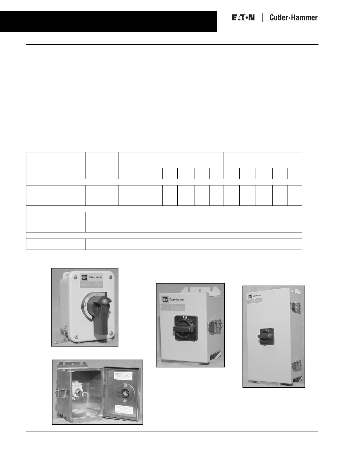
Rotary Disconnect Switches
– Enclosed Switches
Enclosed Rotary
■ 30, 40, 60, 80 Ampere available.
■ 600V, 3 pole, horsepower rated
■ Type 12/3R, 4X Stainless and 4X
Non Metallic Enclosures
■ CSA approved to C22.2 #14 CEC rule
28-602(3) (b) manual motor controller suitable for motor disconnect
■ Accepts auxiliary contacts
■ Capability to signal PLC controller
■ 10 kVA short circuit rating when
used in conjunction with Class J
fusing
Table 17. Rotary Disconnect Switches - Enclosed Switches
Ampere Type 12/3R
Non-Fusible 3 Pole, 600V AC
30
40
60
80
Auxiliary Contacts for Enclosed Rotary Switches
30
40
60
80
Additional Auxiliary Contacts
30 – 80
30 – 80
Type 12 enclosure can be field modified to meet type 3R rainproof requirements when a factory provided drain hole is opened.
The mechanism is reversed on these contacts.
Enclosure
Catalogue
Number
CDR3030UD
CDR3040UD
CDR3060UD
CDR3080UD
➁
CRAC3
➁
CRAC3
➁
CWAC3
➁
CWAC3
➁
CRAB
➁
CRAA
Type 4X
Enc losure
Stainless Steel
Catalogue
Number
CDR3030UW
CDR3040UW
CDR3060UW
CDR3080UW
Auxiliary contact kit contains holder and 1 NO contact
Auxiliary contact kit contains holder and 1 NO contact
Auxiliary contact kit contains holder and 1 NO contact
Auxiliary contact kit contains holder and 1 NO contact
1 NO contact
1 NC contact
Type 4X
Enc losure
Non Metallic
Catalogue
Number
CDR3030UX
CDR3040UX
CDR3060UX
CDR3080UX
Maximum Horsepower Ratings -
120V 280V 240 V 480V 600V 120V 280V 220-
1.5
2
2
3
Volts AC
1 phase AC
2
3
5
7.5
7.5
3
7.5
3
7.5
15
10
20
Maximum Horsepower Ratings -
10
10
20
30
2
2
5
7.5
Volts AC
3 phase AC
240 V
5
7.5
10
15
7.5
December 2004
440-
600V
480V
15
10
15
20
20
20
25
30
40
40
50
CDR3040UX
CDR3030UD
CDR3060UD
CDR3030UW
For more information visit us at: www.eatonelectrical.ca
Page 20

December 2004
[
]
[
]
]
[
]
SC
O
N
US
S
TYPE 12/3R
OSURE.
CDR303UD CDR304UD
Rotary Disconnect Switches
– Enclosed Switches
– Variable Depth
5.19 [132 MM
19
181 MM
.12
.31 [8 MM]
174 MM
.86
6.04 [153 MM]
I ON
0 OFF
.312 DIA. [8 MM]
ENCL
REW TO BE
VED WHE
REM
ED A
TYPE 3R DEVICE
1.84 [47 MM]
1.84 [47 MM]
199 MM
.84
6.00 [152 MM]
4.66 [118 MM]
6.10 [155 MM]
NOTE:
1. WIRE RANGE OF SWITCH LUGS IS #4-#14 COPPER.
WIRE RANGE OF GROUND LUGS IS #2-#14 COPPER OR ALUMINUM.
CDR303
For more information visit us at: www.eatonelectrical.ca
Page 21

20
]
[]
]
[]
[
]
[
]
]
]
]
[
]
]
SC
N
.
[
]
[
]
TYPE 12/3R ENCLOSURE.
Rotary Disconnect Switches
– Enclosed Switches
CDR306UD CDR380UD
December 2004
7.69 [195 MM
5.00 [127 MM
127 MM
.99
336 MM
15.09 [383 MM]
4.82 [122 MM
6.26 [159 MM
NOTE:
1. WIRE RANGE OF SWITCH LUGS IS #4-#14 COPPER.
WIRE RANGE OF GROUND LUGS IS #2-#14 COPPER OR ALUMINUM.
3.25
365 MM
4.37
358 MM
4.11
8.54 [217 MM
127 MM
.99
.312 DIA. [8 MM
REW TO BE REMOVED WHE
ED AS A TYPE 3R DEVICE
For more information visit us at: www.eatonelectrical.ca
Page 22

December 2004
[
]
]
[]
7.26 [184 MM]
[]
[
]
[
]
]
[]
]
UGS IS
.
UGS IS
.
:
Rotary Disconnect Switches
– Enclosed Switches
21
CDR3030UW
CDR3040UW
Type 4X Stainless Enclosure
181 MM
174 MM
.12
.86
6.04 [153 MM]
5.19 [132 MM
1.84 [47 MM]
.312 DIA. [8 MM
199 MM
.84
4.54 [115 MM
NOTE
1. WIRE RANGE OF SWITCH L
WIRE RANGE OF GROUND L
For more information visit us at: www.eatonelectrical.ca
#4-#14 COPPER
#2-#14 COPPER OR ALUMINUM
6.00 [152 MM]
Page 23

22
OFF
ON
0
Rotary Disconnect Switches
– Enclosed Switches
– Flange Mounted – Fixed Depth
December 2004
CDR3080UW
CDR3060UW
Type 4X Stainless Enclosure
15.09 [383 MM]
4.70 [119 MM]
7.42 [188 MM]
13.25 [336 MM]
14.37 [365 MM]
14.11 [358 MM]
.31 [8 MM]
7.69 [195 MM]
5.00 [127 MM]
4.99 [127 MM]
4.99 [127 MM]
.312 DIA. [8 MM]
8.54 [217 MM]
NOTE:
1. WIRE RANGE OF SWITCH LUGS IS #1-#14 COPPER.
WIRE RANGE OF GROUND LUGS IS #2-#14 COPPER OR ALUMINUM.
For more information visit us at: www.eatonelectrical.ca
Page 24

December 2004
]
]
]
]
]
]
[
]
]
]
.
S
[
]
Rotary Disconnect Switches
– Enclosed Switches
23
CDR3040UX
CDR3030UX
Type 4X Non-Metallic Enclosure
6.75 [171 MM]
7.38 [187 MM]
5.44 [138 MM]
5.50 [140 MM]
NOTE:
1. WIRE RANGE OF SWITCH LUGS IS #4-#14 COPPER.
WIRE RANGE OF GROUND LUGS IS #2-#14 COPPER OR ALUMINUM.
ON
OFF
2.00 [51 MM]
3.00 [76 MM]
.312 [8 MM] DIA.
4 MOUNTING HOLES
1.87 [47 MM]
7.47 [190 MM]
1.87 [47 MM]
4.72 [120 MM]
7.43 [189 MM]
CDR3060UX
CDR3080UX
Type 4X Non-Metallic Enclosure
15.75 [400 MM
15.00 [381 MM
NOTE:
1. WIRE RANGE OF SWITCH LUGS IS #1-#14 COPPER.
WIRE RANGE OF GROUND LUGS IS #2-#14 COPPER OR ALUMINUM.
5.00 [127 MM
6.00 [152 MM
8.75 [222 MM
.312 [8 MM] DIA
4 MOUNTING HOLE
142 MM
.58
.58 [142 MM
403 MM
15.88
6.88 [175 MM
9.62 [244 MM
For more information visit us at: www.eatonelectrical.ca
Page 25

24
Operating Mechanisms with Disconnect Switches
– Variable Depth
December 2004
Complete Operating Handle Only —
Mechanism — C361NE1 C361H1
Product Description
Type C361 Disconnect Switches are
suitable for installation in control
enclosures having a right-hand flange.
Fusible disconnect switches will accept
R fuses as standard. Field installable
rejection kits are supplied as standard
on 100A and 200A clips. For 30A and
60A rejection clips, see footnote
The switch is CSA/UL component recognized for use on systems with up to
200,000 rms symmetrical amperes
available fault current when Class R
clips are supplied. A standard connecting rod is supplied with switch.
.
Options and Accessories
Table 1. Electrical Interlocks
Circuit Catalogue
1NO-1NC
2NO-2NC
Table 2. Connecting Rods — Increase
Maximum Allowable Depth by 5 Inches
Application Catalogue
Disconnect Switches
30, 60, 100 and 200A
Circuit Breakers
150, 250 and 400A
Circuit Breakers
600, 800 and 1200A
Number
DS200EK1
DS200EK2
Number
C371CS1
C371CS2
Table 3. Operating Mechanism Variable Depth with Disconnect Switch — Right-Hand Mounting
Disconnect
Switch Size
(Amperes)
30 7 to 16 7-1/2 7-1/2 15 20 5 Non-fusible C361NC C361NC1 C361NC2
60 7 to 16 15 15 30 50 10 Non-fusible C361ND C361ND1 C361ND2
100 7 to 16 25 30 60 75 20 Non-fusible C361NE C361NE1 C361NE2
200 7 to 16 40 60 125 150 40 Non-fusible C361NF C361NF1 C361NF2
Dimension shown is from panel to flange surface.
Refers to rating of switch only.
Components individually boxed and shipped in overpack carton.
For rejection clips, add Suffix Letter R to listed Catalogue Number, and add $9. to price. Example: C361SC121R.
Variable
Depth
Mounting
Range
Minimum/
Maximum
(Inches)
Maximum Horsepower Ratings
AC System Volts
(Motor Volts)
208
240
(230)
480
(460)
(200)
600
(575)
DC Using
2 Poles
250V
Maximum
Fuse Clip Rating
(Amperes) Noninterchangeable
Type for Class
H, J, K or R Type
Fuses Only
250V 600V Catalogue
3060—
60
—
100 100 C361SE263 C361SE1263 C361SE2263
200 200 C361SF264 C361SF1264 C361SF2264
Switch and
Operating
Mechanism Only
DOES NOT
Include Handle
Number
C361SC21
30
C361SC61
3060C361SD22
C361SD62
Switch and Operating Mechanism
with 4-Inch Handle
For NEMA 1 or 12
Enclosure
Catalogue
Number
C361SC121
C361SC161
C361SD122
C361SD162
For NEMA 4
Enclosure
Catalogue
Number
C361SC221
C361SC261
C361SD222
C361SD262
Table 4. Handle Only
Application Operating Handle
For use with 30, 60,
100 and 200 Ampere
Disconnect Switches
Length in Inches
(mm)
4.00 (101.6)
4.00 (101.6)
6.00 (152.4)
6.00 (152.4)
NEMA Type
Enclosure
1-12
4
1-12
4
Catalogue
Number
C361H1
C361H2
C361H3
C361H4
For more information visit us at: www.eatonelectrical.ca
Page 26

December 2004
Technical Data and Specifications
Operating Mechanisms with Disconnect Switches
– Variable Depth
Datum
25
A
G
E
D
.62
(15.7)
F
1.62
(41.1)
Min.
Datum
B
C
Figure 15. Mounting Dimension Requirements
Table 18. Mounting Dimension Requirements
in Inches (mm)
Disconnect Switch Type A B C D E F G
30A and 60A Non-fusible
30A and 60A Fusible
100A Non-fusible
100A Fusible
200A Non-fusible and Fusible
See
Dimensions
Below
See
Dimensions
Below
1.56
(39.6)
1.56
(39.6)
1.75
(44.5)
1.75
(44.5)
3.34
(84.8)
.96
(24.4)
.96
(24.4)
1.10
(27.9)
1.10
(27.9)
0.63
(16.0)
4.00
(101.6)
4.00
(101.6)
5.50
(139.7)
5.50
(139.7)
8.50
(215.9)
3.50
(88.9)
3.50
(88.9)
3.38
(85.9)
3.38
(85.9)
1.84
(46.7)
7.12
(180.8)
9.75
(247.7)
7.12
(180.8)
11.88
(301.8)
15.50
(393.7)
Table 19. Line Lug Data Dimension A = The required wire
Disconnect Switch Size Wire Size
30 Ampere
60 Ampere
100 Ampere
200 Ampere
#2 – 14 Cu/Al
#2 – 14 Cu/Al
1/0 – 14 Cu/Al
250 kcmil – #6 Cu/Al
bending spacing selected from Article
430-10 of the National Electrical Code.
Dimension B = Minimum or maximum
depth from inside of flange holding
operating handle to panel where
Disconnect Switch is mounted.
(Variable 7 to 16 inches.)
For more information visit us at: www.eatonelectrical.ca
Page 27

26
Operating Mechanisms with Disconnect Switches
– Flange Mounted – Fixed Depth
December 2004
Product Description
Type C361 Disconnect Switches are
suitable for installation in control
enclosures having a right-hand flange.
Fusible disconnect switches will accept
R fuses as standard. Field installable
rejection kits are supplied as standard
on 100A and 200A clips. For 30A and
60A rejection clips, see footnote
The switch is CSA/UL component recognized for use on systems with up to
200,000 rms symmetrical amperes
available fault current when Class R
clips are supplied.
Fixed Depth – Flange to Panel
■ 30-60A – 61/2 inches
■ 100A – 7 inches
Table 25. Operating Mechanism Fixed Depth with Disconnect Switch — Right-Hand Mounting
Disconnect
Switch Size
(Amperes)
30 7-1/2 7-1/2 15 20 5 Non-fusible C361FNC1
60 15 15 30 50 10 Non-fusible C361FND1
100 25 30 60 75 20 Non-fusible C361FNE1
Refers to rating of switch only.
For rejection clips, add Suffix Letter R to listed Catalogue Number. Example: C361FSC121R.
Maximum Horsepower Ratings
AC System Volts
(Motor Volts)
208
240
480
(200)
(230)
(460)
600
(575)
DC
Using
2 Poles
250V
Maximum
Fuse Clip Rating
(Amperes) Noninterchangeable
Type for Class
H, J, K or R Type
Fuses Only
250V 600V Catalogue
3060—
60
—
100 100 C361FSE1263
Switch and Operating
Mechanism
with 4-Inch Handle
For NEMA 1 or 12
Enclosure
Number
C361FSC121
C361FSC161
30
3060C361FSD122
C361FSD162
Table 23. Electrical Interlocks
Circuit Catalogue
1NO-1NC
2NO-2NC
Number
DS200EK1
DS200EK2
Table 24. Line Lug Data
Disconnect Switch Size Wire Size
Disconnect Switches
30 Ampere
60 Ampere
100 Ampere
200 Ampere
#2 – 14 AL-CU
#2 – 14 AL-CU
#0 – 14 AL-CU
250 MCM – #6 AL-CU
Table 26. Approximate Dimensions
Frame Size
30-60 Amp. Disc. Switch
150 Amp. Circ. Breaker
100 Amp. Disc. Switch
250 Amp. Circuit Breaker
400 Amp. Circuit Breaker
ABCDE
8-5/8 11-3/8 6-1/2 1-1/2 9-1/2
9-7/8 13-3/8 7 1-1/4 11-3/4
Dimensions in Inches
For more information visit us at: www.eatonelectrical.ca
3/8
D
E
3/8" DIA. HOLES
FOR PANEL SUPPORT
IF NECESSARY
3-3/16
A
DISCONNECT
OR CIRCUIT
BREAKER
5/16
B
5-13/16
1-3/16
C
Page 28

Operating Mechanisms with Disconnect Switches
December 2004
Fuse Clips for Variable or Flange Mount Operating Mechanisms
C351 Fuse Clip Kit
Table 27. C351 — Fuse Clip Selection — 3 Poles
Starter
Size
0 200/230
1 200/230
2 200
3 200
4 200
5 200
Motor
Voltage
460/575
460/575
230
460/575
230
460/575
230
460/575
230
460/575
Fuse clip “R” rejection members for use with Class R fuses are supplied loose in the Fuse Clip Kits.
Maximum
Horsepower
(3-Phase)
Dual Element
Fuses
3
5
7-1/2
10
10
15
25
25
30
50
40
50
100
75
100
200
Fuse Clip
Rating
Amperes Volts Catalogue Number Catalogue Number Catalogue Number Catalogue Number
30
30
30
30
60
60
60
100
100
100
200
200
200
400
400
400
Accessories
For Non-rejection
Type Fuses
250
C351KC21
600
C351KD22-61
250
C351KC21
600
C351KD22-61
250
C351KD22-61
250
C351KD22-61
600
C351KD62
250
C351KE23-63
C351KE23-63
250
C351KE23-63
600
250
C351KF24-64
C351KF24-64
250
C351KF24-64
600
250
Not Available
250
in Kit Form
600
For use w/ “R”
Rejection Type Fuses
C351KC21R
C351KD22-61R
C351KC21R
C351KD22-61R
C351KD22-61R
C351KD22-61R
C351KD62R
C351KE23-63
C351KE23-63
C351KE23-63
C351KF24-64
C351KF24-64
C351KF24-64
Not Available
in Kit Form
Fuse Clip Kit for Field Installation with
Non-fusible Starter
For Form I
Type “J” Fuses
–
C351KD71
–
C351KD71
–
–
C351KD72
–
–
C351KE73
–
–
C351KF74
Not Available
in Kit Form
27
For Form II
Type “C” Fuses
–
C351KD81
–
C351KD81
–
–
C351KD82
–
–
C351KE83
–
–
C351KF84
Not Available
in Kit Form
Note: Kits do not include fuses.
NEMA 12 Safety Door Hardware
Product Selection
Type C361 NEMA 12
Safety Door Hardware
Type C361 Door Hardware Kits are
designed to function with all C361 and
C371 disconnect switches and circuit
breaker operating mechanisms.
These kits are designed for use with
small enclosures up to 40 inches
(1016 mm), intermediate 40 – 60 inches
(1016 – 1524 mm) or larger floor cases
over 60 inches (1524 mm) to provide
enclosure sealing and protection
against unauthorized entry. These
kits can be used on enclosure flanges
with material thickness ranging from
16 gauge through 3/16 inches with
flanges on the right side only. Door
hardware kits are to be installed in a
commercially available enclosure.
Consult the enclosure manufacturer
application data for proper kit selection.
For more information visit us at: www.eatonelectrical.ca
Table 28. Type C361 NEMA 12
Safety Door Hardware
Handle Length
(Inches)
4
6
Roller Latch
The 1/4-inch x 1/2-inch standard mill
rectangular locking bar is not supplied
with these kits.
Third roller latch for use with 4 or 6-inch
handle when 3 point latching is required.
Catalogue
Number
C361KJ4
C361KJ6
C361KR
Page 29

Circuit Breaker Operating Mechanisms
28
Flange Mounted – Fixed Depth
Complete Circuit Breaker
Operating Mechanism with
Operating Handle – C371E1
Table 29. Operating Mechanisms for Circuit Breakers — Flange Mounted Variable Depth
Circuit Breaker or
Motor Circuit
Protector
HMCP, EHD, FDB, FD, FDC, HFD 150 6-1/2 to 16 C371E C371E1 C371E2
HMCP, HJD, JD, JDB, JDC
HMCP, DK, HKD, KD, KDB
HLD, LD, LDC 600 8-1/2 to 22 C371G C371G5 C371G6
MD, MDS
HND, ND, NDC
For increased maximum allowable depth, see Connecting Rods below.
Dimensions shown are from panel flange surface.
Frame
Size
250
400
800
1200
Product Description
Type C371 Circuit Breaker Operating
Mechanisms are designed for installation in control enclosures where main
or branch circuit protective devices are
required. All circuit breaker mechanisms are suitable for right hand
mounting.
Auxiliary contacts are not available for
mounting on operating mechanism.
Where required, have them installed in
circuit breaker.
Handle Only – C371H1
Variable Depth
Mounting
Range
Min./Max.
(Inches)
6-1/2 to 16-5/8 C371F C371F5 C371F6
8-3/4 to 22
9-3/4 to 22
Operating
Mechanism Only
– Does Not
Include Handle
Catalogue
Number
C371K C371K5 C371K6
Operating Mechanism With 4 Inch Handle & Rod
For NEMA 1-12 Enclosure For NEMA 4 Enclosure
Catalogue Number Catalogue Number
December 2004
Table 30. Handle Only
Circuit Breaker
Frame Size
(Amperes)
150 1-3R-3-12
250 thru
1200
NEMA
Enclosure
Type
4
1-3R-3-12
4
1-3R-3-12
4
1-3R-3-12
4
Operating
Handle
Length
4 Inches
4 Inches
6 Inches
6 Inches
4 Inches
4 Inches
6 Inches
6 Inches
Catalogue
Number
C371H1
C371H2
C371H3
C371H4
C371H5
C371H6
C371H7
C371H8
+
Motor Circuit Protectors
Circuit Breakers
Channel Support Kit –
Rod not supplied in Kit
For use to prevent bending of the operating handle mounting surface. This is especially
useful when the operating handle is mounted on a channel in a multi-door enclosure.
Kit included in 600 through 1200 ampere mechanisms. Catalogue Number C371CS6
Table 31. Connecting Rods
Increase Maximum Allowable Depth by 5 Inches
Application Catalogue Number
Disconnect Switches
30 , 60, 100, 200 Ampere
Circuit Breakers
150, 250, 400 Ampere
Circuit Breakers
600, 800, 1200 Ampere
C371CS1
C371CS2
For Safety Door Hardware – see Page 27
Listed Above
Operating Mechanisms
+
Listed Above
Operating Handle
For more information visit us at: www.eatonelectrical.ca
Page 30

Circuit Breaker Operating Mechanisms
December 2004
Mounting Dimension Requirements
Dimension A = 0.75 in. plus the required wire bending spacing selected from
Article 430-10 of the National Electrical Code.
Dimension B = Minimum or maximum depth from inside of flange holding
operating handle to panel where Circuit Breaker is mounted.
(variable depth, see page 22)
Dimension C = 150 Ampere Size – 0.67 in.
250 Ampere Size – 0.625 in.
400 Ampere Size – 0.187 in.
600 Ampere Size – 1.71 in.
800 – 1200 Ampere Size – 5.17 in.8
Flange – Variable Depth, Flange Mounted – Fixed Depth
29
Technical Data and Specifications
Product Description
Type C371 Circuit Breaker Operating
Mechanisms are designed for installation in control enclosures with a right
hand flange and where main or branch
circuit protective devices are required.
Auxiliary contacts are not available for
mounting on operating mechanism.
Where required, have them installed in
circuit breaker.
Table 32. Flange Mounted Fixed Depth Operating Mechanisms for Circuit Breaker
Circuit or
Motor Circuit
Protector
HMCP, EHD, FDB, FD, FDC, HFD 150 6-1/2 C371FE1
HMCP, HJD, JD, JDB, JDC
HMCP, DK, HKD, KD, KDB
Frame
Size
250
400
Variable Depth
Mounting
Range
Min./Max.
(Inches)
7 C371FF1
Operating Mechanism With 4 Inch Handle
For NEMA 1 or 12 Enclosure
Catalogue Number
For more information visit us at: www.eatonelectrical.ca
Page 31

30
Notes
NOTES
December 2004
For more information visit us at: www.eatonelectrical.ca
Page 32

December 2004
Notes
31
For more information visit us at: www.eatonelectrical.ca
Page 33

32
Notes
December 2004
For more information visit us at: www.eatonelectrical.ca
Page 34

Eaton Corporation is a diversified industrial manufacturer with 2003 sales
s
t
c
© 2004 Eaton Corporation
All Rights Reserved
Pub. No.PG.35G.02.T.K
December 2004
Printed in Canada
Eaton Corporation
3228 South Service Road
Burlington, ON L7N 3H8
Canada
1-800-268-8378
www.eatonelectrical.ca
of $8.1 billion. Eaton is a global leader in fluid power systems and service
for industrial, mobile and aircraft equipment; electrical systems and
components for power quality,distribution and control; automotive engine
air management systems, powertrain solutions and specialty controls for
performance, fuel economy and safety; and intelligent truck drivetrain sys
for safety and fuel economy. Eaton has 55,000 employees and sells produ
to customers in more than 100 countries. For more information,
visit www.eaton.com.
 Loading...