


PC1616 / PC1832 / PC1864
This manual contains information on limitations regarding product use and function and information on the limitations as to liability of the manufacturer. The entire manual should be carefully read.
Reference Manual
PC1616/PC1832/PC1864 v4.1
DLS2002 and higher
WWW.DIYALARMFORUM.COM

Table of Contents
Section 1: Introduction |
1 |
1.1 About the PC1616/PC1832/PC1864 System . . . . . . . |
1 |
1.2About the PC1616/PC1832/PC1864 Manual Set . . . . 1
Reference Manual . . . . . . . . . . . . . . . . . . . . . . . . . . . . 1
Installation Guide . . . . . . . . . . . . . . . . . . . . . . . . . . . . . 1
Programming Worksheets . . . . . . . . . . . . . . . . . . . . . . 1
User Guide . . . . . . . . . . . . . . . . . . . . . . . . . . . . . . . . . . 1
1.3Control and Indicating Equipment Specifications . . . . 1
Zone Configuration . . . . . . . . . . . . . . . . . . . . . . . . . . . . 1 Access Codes. . . . . . . . . . . . . . . . . . . . . . . . . . . . . . . . 1 Warning Device output . . . . . . . . . . . . . . . . . . . . . . . . . 2 Memory. . . . . . . . . . . . . . . . . . . . . . . . . . . . . . . . . . . . . 2 Programmable Outputs (PGMs) . . . . . . . . . . . . . . . . . . 2 Power Supply . . . . . . . . . . . . . . . . . . . . . . . . . . . . . . . . 2 Operating Environmental Conditions . . . . . . . . . . . . . . 2 Keypad Specifications . . . . . . . . . . . . . . . . . . . . . . . . . 2 Alarm Transmitter Equipment (ATE) Specification . . . . 2 System Supervision Features. . . . . . . . . . . . . . . . . . . . 2 False Alarm Prevention Features . . . . . . . . . . . . . . . . . 2 Additional Features. . . . . . . . . . . . . . . . . . . . . . . . . . . . 2
1.4 Additional Devices . . . . . . . . . . . . . . . . . . . . . . . . . . . . 3
Keypads . . . . . . . . . . . . . . . . . . . . . . . . . . . . . . . . . . . . 3
PC5100 2-Wire Addressable Interface Module . . . . . . 3
PC5108 Eight Zone Expander Module . . . . . . . . . . . . . 3
PC5132 Wireless Receiver Module . . . . . . . . . . . . . . . 3
PC5200 Power Supply Output Module . . . . . . . . . . . . . 3
PC5204 Power Supply Output Module . . . . . . . . . . . . . 3
PC5208 Eight Low Current Output Module . . . . . . . . . 3
Escort5580(TC) Module . . . . . . . . . . . . . . . . . . . . . . . . 3
PC5900 Audio Verification Module . . . . . . . . . . . . . . . . 3
PC5400 Printer Module . . . . . . . . . . . . . . . . . . . . . . . . 3
PC5401 Serial Interface Module. . . . . . . . . . . . . . . . . . 3
T-Link Local Area Network Communicator . . . . . . . . . . 3
TL250/TL300 Intranet/Internet Communicators . . . . . . 3
Alternate Communicators . . . . . . . . . . . . . . . . . . . . . . . 3
PC5700/PC5720 Fire Module. . . . . . . . . . . . . . . . . . . . 4
Enclosures/Cabinets. . . . . . . . . . . . . . . . . . . . . . . . . . . 4
1.5 Battery Standby Times versus AUX Load . . . . . . . . . . 4
Section 2: Installation and Wiring |
5 |
2.1 Installation Steps . . . . . . . . . . . . . . . . . . . . . . . . . . . . . 5
2.2 Terminal Descriptions . . . . . . . . . . . . . . . . . . . . . . . . . 5
AC Power Terminals. . . . . . . . . . . . . . . . . . . . . . . . . . . 5 Battery Connection . . . . . . . . . . . . . . . . . . . . . . . . . . . . 5 Auxiliary Power Terminals - AUX+ and GND . . . . . . . . 5 Bell Output Terminals - BELL+ and BELL- . . . . . . . . . . 5 Keybus Terminals - RED, BLK, YEL, GRN. . . . . . . . . . 6 Programmable Outputs - PGM1 to PGM4 . . . . . . . . . . 6 Zone Input Terminals - Z1 to Z8 . . . . . . . . . . . . . . . . . . 6 Telephone Connection Terminals - TIP,RING,T-1,R-1. 6
2.3 Wire Routing for Power & Non-Power Limited . . . . . . . 6
2.4 Keybus Operation and Wiring . . . . . . . . . . . . . . . . . . . 6
2.5 Current Ratings - Modules & Accessories . . . . . . . . . .6
PC1616/PC1832/PC1864 Device Ratings. . . . . . . . . . 7
System Output Ratings . . . . . . . . . . . . . . . . . . . . . . . . 7
2.6 Assigning Zones to Zone Expanders . . . . . . . . . . . . . .7
2.7 Keypad Assignment . . . . . . . . . . . . . . . . . . . . . . . . . . .7
How to Assign Keypads. . . . . . . . . . . . . . . . . . . . . . . . 7 Function Key Programming . . . . . . . . . . . . . . . . . . . . . 8
2.8 Confirming Module Supervision . . . . . . . . . . . . . . . . . .8
2.9 Removing Modules . . . . . . . . . . . . . . . . . . . . . . . . . . . .8
2.10 Zone Wiring . . . . . . . . . . . . . . . . . . . . . . . . . . . . . . . . .8
Burglary Zone Wiring Chart . . . . . . . . . . . . . . . . . . . . . 8 Normally Closed (NC) Loops . . . . . . . . . . . . . . . . . . . . 8 Single End Of Line (EOL) Resistors . . . . . . . . . . . . . . 9 Double End of Line (DEOL) Resistors . . . . . . . . . . . . . 9 Fire Zone Wiring - 4-wire Smoke Detectors. . . . . . . . . 9 Compatible 4-Wire Smoke Detectors . . . . . . . . . . . . . 9 Fire Zone Wiring - 2-wire Smoke Detectors. . . . . . . . . 9 Compatible 2-Wire Smoke Detectors . . . . . . . . . . . . 10 2-Wire Smoke Detector Initating Circuit. . . . . . . . . . . 10 Keyswitch Zone Wiring . . . . . . . . . . . . . . . . . . . . . . . 10
2.11 Keypad Zone/PGM . . . . . . . . . . . . . . . . . . . . . . . . . . .10
Assigning Keypad Zones. . . . . . . . . . . . . . . . . . . . . . 10
2.12 Zone Activity Log . . . . . . . . . . . . . . . . . . . . . . . . . . . .10
Section 3: How to Program |
11 |
3.1 How to Enter Installer Programming . . . . . . . . . . . . . .11
LED Keypad. . . . . . . . . . . . . . . . . . . . . . . . . . . . . . . . 11
LCD Keypad . . . . . . . . . . . . . . . . . . . . . . . . . . . . . . . 11
3.2 Programming Decimal Data . . . . . . . . . . . . . . . . . . . .11
3.3 Programming Hexadecimal Data . . . . . . . . . . . . . . . .11
3.4 Programming Toggle Options . . . . . . . . . . . . . . . . . . .11
3.5 Viewing Programming . . . . . . . . . . . . . . . . . . . . . . . . .11
LED and ICON Keypads . . . . . . . . . . . . . . . . . . . . . . 11
LCD Keypad . . . . . . . . . . . . . . . . . . . . . . . . . . . . . . . 11
Section 4: Keypad Commands |
12 |
4.1 Arming and Disarming . . . . . . . . . . . . . . . . . . . . . . . |
.12 |
Arming . . . . . . . . . . . . . . . . . . . . . . . . . . . . . . . . . . . . 12
Stay and Away Arming . . . . . . . . . . . . . . . . . . . . . . . 12
Stay Arming . . . . . . . . . . . . . . . . . . . . . . . . . . . . . . . . 12
Away Arming . . . . . . . . . . . . . . . . . . . . . . . . . . . . . . . 12
Disarming. . . . . . . . . . . . . . . . . . . . . . . . . . . . . . . . . . 13
Event Buffer (Event Log) . . . . . . . . . . . . . . . . . . . . . . 13
Viewing the Event Buffer . . . . . . . . . . . . . . . . . . . . . . 13
4.2 [*] Commands . . . . . . . . . . . . . . . . . . . . . . . . . . . . . . .13
[*][1] Zone Bypassing. . . . . . . . . . . . . . . . . . . . . . . . . 13 [*][2] Trouble Display . . . . . . . . . . . . . . . . . . . . . . . . . 13 [*][3] Alarm Memory . . . . . . . . . . . . . . . . . . . . . . . . . . 14 [*][4] Door Chime On/Off . . . . . . . . . . . . . . . . . . . . . . 14 [*][5] Programming Access Codes. . . . . . . . . . . . . . . 14
WWW.DIYALARMFORUM.COM
i

Installer’s Programming - Codes and Options . . . . . 15 [*][6] User Functions . . . . . . . . . . . . . . . . . . . . . . . . . 16 LCD Keypad User Functions . . . . . . . . . . . . . . . . . . 16 [*][7] Command Output Functions . . . . . . . . . . . . . . 16 [*][8] Installer Programming . . . . . . . . . . . . . . . . . . . 16 [*][9] Arming Without Entry Delay . . . . . . . . . . . . . . . 16 [*][0] Quick Arm. . . . . . . . . . . . . . . . . . . . . . . . . . . . . 17 [*][0] Quick Exit . . . . . . . . . . . . . . . . . . . . . . . . . . . . . 17
4.3 Function Keys . . . . . . . . . . . . . . . . . . . . . . . . . . . . . . 17
4.4 Global and Partition Keypad Operation . . . . . . . . . . . 18
4.5 Keypad Features . . . . . . . . . . . . . . . . . . . . . . . . . . . . 18
Automatic Scrolling of Open Zones . . . . . . . . . . . . . 18
Automatic Scrolling of Alarms in Memory . . . . . . . . . 18
24 Hour Time Display Option . . . . . . . . . . . . . . . . . . 18
Keypad Zones. . . . . . . . . . . . . . . . . . . . . . . . . . . . . . 18
Viewing Troubles While Armed. . . . . . . . . . . . . . . . . 18
Backlighting Boost . . . . . . . . . . . . . . . . . . . . . . . . . . 18
Section 5: Programming Sections |
19 |
5.1 Keypad Programming . . . . . . . . . . . . . . . . . . . . . . . . 19
5.2 Basic Programming . . . . . . . . . . . . . . . . . . . . . . . . . . 19
[001]-[004] - Zone Definitions . . . . . . . . . . . . . . . . . . 19
[005] - System Times . . . . . . . . . . . . . . . . . . . . . . . . 21
[006] - Installer’s Code . . . . . . . . . . . . . . . . . . . . . . . 21
I[007] - Master Code . . . . . . . . . . . . . . . . . . . . . . . . . 21
[008] - Maintenance Code/Guard Code . . . . . . . . . . 21
[009]-[011] - Programmable Output Options. . . . . . . 21
[012] - Keypad Lockout Options . . . . . . . . . . . . . . . . 24
[013] - First System Option Codes . . . . . . . . . . . . . . 24
[014] - Second System Option Codes . . . . . . . . . . . 25
[015] - Third System Option Codes . . . . . . . . . . . . . 26
[016] - Fourth System Option Codes . . . . . . . . . . . . 27
[017] - Fifth System Option Codes . . . . . . . . . . . . . . 27
[018] - Sixth System Option Codes. . . . . . . . . . . . . . 28
[019] - Seventh System Option Codes . . . . . . . . . . . 29
[020] - Keypad Zone Assignment . . . . . . . . . . . . . . . 30
[021] - Eighth System Option Codes . . . . . . . . . . . . 30
[023] - Tenth System Option Codes . . . . . . . . . . . . . 32
[030] - Fast Loop Response . . . . . . . . . . . . . . . . . . . 33
5.3 Advanced Programming . . . . . . . . . . . . . . . . . . . . . . 33
[101]-[164] - Zone Attributes . . . . . . . . . . . . . . . . . . . 33 [165] - Maximum Dialing Attempts . . . . . . . . . . . . . . 33 [166] - Post Dial Wait For Handshake . . . . . . . . . . . 33 [167] - T-Link Communications Wait for Acknowledge Delay. . . . . . . . . . . . . . . . . . . . . . . . . . . . . . . . . . . . . 33 [168]-[169] - Daylight Saving Time . . . . . . . . . . . . . . 33 [170] - PGM Output Timer . . . . . . . . . . . . . . . . . . . . 34 [171] - Tamper PGM Output Timer . . . . . . . . . . . . . 34 [172] - Settle Delay Timer . . . . . . . . . . . . . . . . . . . . . 34 [173] - Bell Delay Timer . . . . . . . . . . . . . . . . . . . . . . 34 [175] - Auto-arm Postpone Timer . . . . . . . . . . . . . . . 34 [176] - Cross Zone/Police Code Timer . . . . . . . . . . . 34 [178] - For Future Use . . . . . . . . . . . . . . . . . . . . . . . 34 [181]-[188] - Auto-arm Schedules. . . . . . . . . . . . . . . 34 [190] - No Activity Arming Pre-Alert Duration . . . . . . 34 [191]-[198] - No-Activity Timer (Partition 1-8) . . . . . . 35 [199] - Auto-arming Pre-Alert Time. . . . . . . . . . . . . . 35
5.4 Partition & Zone Programming . . . . . . . . . . . . . . . . . |
35 |
[201] - Partition Selection Mask . . . . . . . . . . . . . . . . 35
[202]-[265] - Partition Zone Assignments . . . . . . . . . 35
Partitions and Zone Assignment . . . . . . . . . . . . . . . . 35
5.5 Communicator Programming . . . . . . . . . . . . . . . . . . 35
Communicator - Telephone Numbers . . . . . . . . . . . . 35 [301] - First Telephone Number. . . . . . . . . . . . . . . . . 35 [302] - Second Telephone Number . . . . . . . . . . . . . . 35 [303] - Third Telephone Number . . . . . . . . . . . . . . . . 35 [304] - Call Waiting Cancel Dialing String . . . . . . . . . 35 Communicator - Account Codes . . . . . . . . . . . . . . . . 36 [310] - System Account Code . . . . . . . . . . . . . . . . . . 36 [311]-[318] - Partition 1-8 Account Codes . . . . . . . . . 36 Reporting Codes . . . . . . . . . . . . . . . . . . . . . . . . . . . . 36 Communicator - Reporting Codes . . . . . . . . . . . . . . . 36 [320]-[323] - Alarm Reporting Codes, Zones 1 to 64 . 36 [324]-[327] - Alarm Restoral Reporting Codes,
Zones 1 to 64. . . . . . . . . . . . . . . . . . . . . . . . . . . . . . . 36 [328] - Miscellaneous Alarm Reporting Codes . . . . . 36 [329] - Priority Alarm/Restoral Reporting Codes . . . . 36 [330]-[333] - Tamper Reporting Codes, Zones 1 to 64 36 [334]-[337] - Tamper Reporting Codes, Zones 1 to 64 37 [338] - Miscellaneous Tamper Reporting Codes . . . . 37 [339]-[340] - Closing (Arming) Reporting Codes,
Zones 1-32. . . . . . . . . . . . . . . . . . . . . . . . . . . . . . . . . 37 [341] - Miscellaneous Closing (Arming) Reporting Codes . . . . . . . . . . . . . . . . . . . . . . . . . . . . . . . . . . . . 37 [342]-[343] - Opening (Disarming) Reporting Codes Access Codes 1 to 32 . . . . . . . . . . . . . . . . . . . . . . . . 37 [344] - Miscellaneous Opening (Disarming) Reporting Codes . . . . . . . . . . . . . . . . . . . . . . . . . . . . . . . . . . . . 37 [345] - Maintenance Alarm Reporting Codes. . . . . . . 37 [346] - Maintenance Alarm Reporting Codes. . . . . . . 37 [347] - Miscellaneous Maintenance Reporting Codes 38 [348] - Test Transmission Reporting Codes . . . . . . . 38 [349] - PC5700 Maintenance Reporting Codes . . . . . 38 [350] - Communicator Format Options . . . . . . . . . . . 38 Reporting Codes . . . . . . . . . . . . . . . . . . . . . . . . . . . . 38 Contact ID . . . . . . . . . . . . . . . . . . . . . . . . . . . . . . . . . 38 SIA (Level 2) . . . . . . . . . . . . . . . . . . . . . . . . . . . . . . . 39 Residential Dial . . . . . . . . . . . . . . . . . . . . . . . . . . . . . 39 Private Line Format . . . . . . . . . . . . . . . . . . . . . . . . . . 39 Pager Format. . . . . . . . . . . . . . . . . . . . . . . . . . . . . . . 39 Pulse Formats . . . . . . . . . . . . . . . . . . . . . . . . . . . . . . 40 Scantronics Format . . . . . . . . . . . . . . . . . . . . . . . . . . 40 Robofon Format. . . . . . . . . . . . . . . . . . . . . . . . . . . . . 40 200 Baud FSK (CESA) . . . . . . . . . . . . . . . . . . . . . . . 40 Telephone Line Monitoring (TLM) . . . . . . . . . . . . . . . 41 [351]-[376] - Communicator Call Directions. . . . . . . . 41 [377] - Communication Variables. . . . . . . . . . . . . . . . 41 [378] - Test Transmission Time of Day . . . . . . . . . . . 42 [379] - Periodic DLS Time of Day . . . . . . . . . . . . . . . 42 [380] - First Communicator Option Codes . . . . . . . . . 42 [381] - Second Communicator Option Codes . . . . . . 43 [382] - Third Communicator Option Codes . . . . . . . . 44
5.6 Downloading Options . . . . . . . . . . . . . . . . . . . . . . . . 45
Downloading . . . . . . . . . . . . . . . . . . . . . . . . . . . . . . . 45 [401] - First Downloading Option Codes . . . . . . . . . . 45 [402] - Downloading Computer’s Phone Number . . . 46 [403] - Downloading Access Code. . . . . . . . . . . . . . . 46 [404] - Panel Identification Code . . . . . . . . . . . . . . . . 46 [405] - Double-Call Timer. . . . . . . . . . . . . . . . . . . . . . 46 [406] - Number of Rings to Answer On . . . . . . . . . . . 46 [499] - Initiate PC-Link Communications . . . . . . . . . . 46
WWW.DIYALARMFORUM.COM
ii

5.7 Programmable Output Programming . . . . . . . . . . . . 46
[501]-[514] - Programmable Output Attributes . . . . . . 46 Assigning Partitions to Programmable Outputs . . . . . 46 [551]-[564] - PGM Partition Assignment. . . . . . . . . . . 47
5.8 International Programming . . . . . . . . . . . . . . . . . . . . 47
[700] - Automatic Clock Adjust . . . . . . . . . . . . . . . . . . 47
[701] - First International Option Codes . . . . . . . . . . . 48
[702] - Second International Option Codes . . . . . . . . 48
[703] - Delay Between Dialing Attempts. . . . . . . . . . . 49
5.9 Module Programming . . . . . . . . . . . . . . . . . . . . . . . . 49
5.10 Special Installer Instructions . . . . . . . . . . . . . . . . . . . 49
[900] - Panel Version . . . . . . . . . . . . . . . . . . . . . . . . . 49 [901] - Installer Walk Test Mode Enable / Disable . . . 49 [902] - Reset Module Supervision . . . . . . . . . . . . . . . 49 [903] - Module Supervision Field . . . . . . . . . . . . . . . . 49 [904] - Module Placement Test . . . . . . . . . . . . . . . . . 50 [906] - For Future Use . . . . . . . . . . . . . . . . . . . . . . . . 50 [989][Installer Code] - Default Master Code . . . . . . . . 50 [990][Installer Code] - Installer Lockout Enable . . . . . 50 [991][Installer Code] - Installer Lockout Disable. . . . . 50 [993]-[999] - Factory Defaults. . . . . . . . . . . . . . . . . . . 50 [993][Installer Code] - Restore Alternate Comm.
Factory Default Programming . . . . . . . . . . . . . . . . . . 50 [995][Installer Code] - Restore ESCORT5580(TC) Factory Default Programming . . . . . . . . . . . . . . . . . . 50 [996][Installer Code] - Restore PC5132 Wireless Factory Default Programming . . . . . . . . . . . . . . . . . . 50 [997][Installer Code] - Restore PC5400 Factory
Default Programming . . . . . . . . . . . . . . . . . . . . . . . . . 50 [998][Installer Code] - Restore PC5900 Factory
Default Programming . . . . . . . . . . . . . . . . . . . . . . . . . 50 [999][Installer Code] - Restore Factory Default Programming . . . . . . . . . . . . . . . . . . . . . . . . . . . . . . . 50
Section 6: Fire Monitoring |
51 |
6.1 Partitions and Fire System Configuration . . . . . . . . . .51
Fire Configuration 1 . . . . . . . . . . . . . . . . . . . . . . . . . . 51
Fire Configuration 2 . . . . . . . . . . . . . . . . . . . . . . . . . . 51
6.2 Fire Zones . . . . . . . . . . . . . . . . . . . . . . . . . . . . . . . . .51
Standard Fire Operation . . . . . . . . . . . . . . . . . . . . . . 51
Auto Verify Fire . . . . . . . . . . . . . . . . . . . . . . . . . . . . . 51
Four-Wire Smoke Detector Zones. . . . . . . . . . . . . . . 51
Two-Wire Smoke Detector Zones . . . . . . . . . . . . . . . 52
Fire Supervisory Zone . . . . . . . . . . . . . . . . . . . . . . . . 52
6.3 Fire System Operation . . . . . . . . . . . . . . . . . . . . . . . .52
Manual Signal Silence . . . . . . . . . . . . . . . . . . . . . . . . 52
Automatic Signal Silence (Bell Time-out) . . . . . . . . . 52
Manual Sensor Reset ([*][7][2]) . . . . . . . . . . . . . . . . . 52
Subsequent Alarm Operation . . . . . . . . . . . . . . . . . . 52
Auto-Scroll LCD Keypad Display. . . . . . . . . . . . . . . . 52
Fire Trouble Conditions . . . . . . . . . . . . . . . . . . . . . . . 52
AC Delays . . . . . . . . . . . . . . . . . . . . . . . . . . . . . . . . . 53
Fire Reporting Codes . . . . . . . . . . . . . . . . . . . . . . . . 53
Section 7: Listing Requirements |
54 |
7.1UL Listed Commercial and Residential Installations .54
Appendix A: Reporting Codes . . . . . . . . . . . . . . . . . . . . . .56
Contact ID . . . . . . . . . . . . . . . . . . . . . . . . . . . . . . . . . 56 SIA Format - Level 2 (Hardcoded). . . . . . . . . . . . . . . 56 Contact ID Zone Alarm/Restoral Event Codes . . . . . 57 SIA Format Automatic Zone Alarm/Restoral Codes . 57
Appendix B: Wiring Diagrams . . . . . . . . . . . . . . . . . . . . . .58
B.1 PC1616/PC1832/PC1864 UL/ULC Wiring Diagram . . . . .58 B.2 PC1616/PC1832/PC1864 Standard Wiring Diagram . . . .59 B.3 PC1616/PC1832/PC1864 European Wiring Diagram . . . .60 B.4 PC1616/PC1832/PC1864 and PC5700 Fire Module Communications Connections . . . . . . . . . . . . . . . . . . . . . . .61 B.5 Sensor Reset for 2-Wire Smoke Detectors . . . . . . . . . . . .61 B.6 Sensor Reset for 4-wire Smoke Detectors . . . . . . . . . . . .61 B.7 Other PGM Connections . . . . . . . . . . . . . . . . . . . . . . . . .61
The below symbols are used to indicate features that are only available in a particular market. No symbol indicates the feature is available for all markets.
EN |
IMQ |
CP-01 |
UK |
C |
Europe |
Italy |
United States |
United Kingdom |
Scandinavia |
WWW.DIYALARMFORUM.COM
iii

Section 1: Introduction
1.1 About the PC1616/PC1832/PC1864 System
This product is in conformity with EMC Directive 89/336/EEC based on results using harmonized standards in accordance with article 10(5), R&TTE Directive 1999/5/EC based on following Annex III of the directive and LVD Directive 73/23/EEC as amended by 93/68/EEC based on results using harmonized standards.
This product meets the requirements of Class II, Grade 2 equipment as per EN 50131-1:2004 Standard. This product is suitable for use in systems with the following notification options:
•A (use of two warning devices and internal dialer required),
•B (self powered warning device and internal dialer required),
•D (use of DSC model T-Link TL250 encrypted Ethernet communicator required).
The PC1616/PC1832/PC1864 are high end security systems. Below are the list of features for each panel:
|
PC1616 |
PC1832 |
PC1864 |
|
|
|
|
|
|
On-board Zones |
6 |
8 |
8 |
|
|
|
|
|
|
Hardwired Zones |
16 (1xPC5108) |
32(3xPC5108) |
64 (7xPC5108) |
|
|
|
|
|
|
Wireless Zones |
16 |
32 |
32 |
|
|
|
|
|
|
Keypad Zone |
8 |
8 |
8 |
|
Support |
||||
|
|
|
||
|
|
|
|
|
On-board PGM |
PGM 1 - 50mA |
PGM 1 - 50mA |
PGM 1/3/4 - 50mA |
|
Outputs |
PGM 2 - 300mA |
PGM 2 - 300mA |
PGM 2 - 300mA |
|
|
|
|
|
|
Additional PGM |
PC5208 - 8x50mA |
PC5208 - 8x50mA |
PC5208 - 8x50mA |
|
Outputs |
PC5204 - 4x500mA |
PC5204 - 4x500mA |
PC5204 - 4x500mA |
|
|
|
|
|
|
Keypads |
8 |
8 |
8 |
|
|
|
|
|
|
Partitions |
2 |
4 |
8 |
|
|
|
|
|
|
User Codes |
32 + Master Codes |
32 + Master Codes |
32 + Master Codes |
|
|
|
|
|
|
Event Buffer |
500 Events |
500 Events |
500 Events |
|
|
|
|
|
|
Transformer |
16.5VAC |
16.5VAC |
16.5VAC |
|
Required |
40VA |
40VA |
40VA |
|
|
|
|
|
|
Battery Required |
4Ah / 7Ah / 14Ah |
4Ah / 7Ah / 14Ah |
4Ah / 7Ah / 14Ah |
|
|
|
|
|
|
Bell Output |
12V 700 mA |
12V 700 mA |
12V 700 mA |
|
(continuous) |
(continuous) |
(continuous) |
||
|
||||
|
|
|
|
The LCD keypad guides users through their available options with easy-to-understand prompts.
The status of the PC1616/PC1832/PC1864 system can be monitored over telephone lines, or using an alternative communicating device, including Skyroute™, T-LINK, GS-3050 and DVACS.
You can program the PC1616/PC1832/PC1864 using any system keypad, or using DLS downloading software and a computer (see section 3, ‘How to Program’).
Review the complete manual set before installing the PC1616/PC1832/PC1864 security system.
1.2About the PC1616/PC1832/PC1864 Manual Set
Reference Manual
This manual provides:
•An overview of the system (Section 1: “Introduction”)
•How to install and wire the system and its modules (Section 2: “Installation and Wiring”)
•How to program the system (Section 3: “How to Program”)
•An introduction to the user interface and keypad operation (Section 4: “Keypad Commands”)
•An overview of the main system programming sections (Section 5: “Programming Sections”).
Installation Guide
The Installation Guide provides the basic installation, wiring and programming information required to program the PowerSeries PC1616, PC1832 and PC1864 control panels.
Programming Worksheets
The Programming Worksheets provid a detailed list of all programming sections available in the panel and a place to record your programming. Be sure to record all your system programming in the Programming Worksheets. If adding modules to your PowerSeries Control Panel, refer to the
Installation Instructions that come with each module.
User Guide
One user guide comes with the PC1616/PC1832/PC1864 system. The User’s Guide provides easy to follow instructions for end users. Installers should also review this manual, in order to properly instruct the end-users once the installation is complete.
1.3Control and Indicating Equipment Specifications
Zone Configuration
•6 Fully programmable zones (PC1616)
•8 Fully programmable zones (PC1832/PC1864)
•34 zone types, 9 programmable zone attributes
•Zone configurations available: Normally closed, Single EOL and Double EOL zone supervision
•Hardwired zone expansion (fully supervised) available using the Model PC5108 (eight Zone Expander Module) and the Model PC5700 (Fire Module)
•Expandable to 16 zones (PC1616)
•Expandable to 32 zones (PC1832)
•Expandable to 64 zones (PC1864)
•One zone input available on the keypads
•Wireless zone expansion (fully supervised) available using the Model PC5132 (RF Receiver, operating at 433MHz)
NOTE: PC1616 expandable to 16 zones only.
•Up to 2 partitions (PC1616)
•Up to 4 partitions (PC1832)
•Up to 8 partitions (PC1864)
Access Codes
•39 access codes:
•32 User Codes (Level 2)
•1 System Master Code (Level 3)
•2 Supervisor Codes
•2 Duress Codes
•1 Maintenance/Guard Code
•1 Installer Code (Level 3)
•Programmable attributes for each user code (see section 4.2 for details)
•1,000,000 access code variations (using 6-digit codes)
•Duress codes derived from user codes plus 1 digit are not allowed
WWW.DIYALARMFORUM.COM
1

Warning Device output
•Rated 12VDC, 700mA, (current limit 2.0A) supervised (EOL resistor shall be used)
•Programmable as steady, pulsed or temporal three (as per ISO 8201) output
•Fire alarm notification has priority over burglary alarm notification
Memory
•CMOS EEPROM memory
•Retains programming and system status on AC and battery failure
•Data Retention: 200 years min.
Programmable Outputs (PGMs)
•Up to 14 programmable outputs (PGM) with 21 options
•PGM outputs are open collector type and switched to ground
•Three low current (50mA) PGM outputs on main panel (PGM1, PGM3, PGM4)
NOTE: PGM3 and PGM4 available on PC1864 only.
•One high current (300mA) output with 2-wire smoke detector capability on the main control board (PGM2)
•Eight additional low current outputs (50mA) available using the Model PC5208
•Four high current outputs (1A) available using the Model PC5204 (one configurable as a supervised bell output)
Power Supply
•1.5A regulated (1.7A for UL/ULC), supervised and integral to the control unit
•Type A as per EN50131-6 Standard
•Input ratings: 120V, 60Hz Class II (220V-240Vac, 50/ 60Hz, 200mA for European installations)
•Transformer required, mounted in the same enclosure, permanently connected for European installations
•Transformer secondary ratings: 16.5Vac, 40VA min
•AUX Output Voltage: 12VDC, -15%/+10% when AC Input Voltage is 85% to +110% of rated value and output current is 500mA (700mA for UL/ULC) (550mA for IMQ)
•Output ripple voltage: 270mVp-p max.
•Storage device: Rechargeable battery, rated 12VDC
•Battery capacity: 4Ah, 7Ah, 14Ah (2 x 7Ah) or 24 Ah (2 x 12Ah)
•Battery = One 12V 4Ah battery (For burglary applications)
•Battery = Two 12V 7Ah (min.) rechargeable sealed lead acid for 24-hr backup (For fire monitoring applications)
•Maximum standby time 24Ah (when using 14Ah battery capacity and AUX current limited to 480mA max.).
•Recharging time 48h
•Programmable recharging current: Low 400mA, High 700mA
•Low battery trouble indication threshold 11.5VDC
•Battery deep discharge protection (cut-off at 9.5VDC)
•Main board current draw: 85mA (set and unset state)
•Resettable fuses (PTC) used on circuit board instead of replaceable fuses
•Supervision for loss of primary power source (AC Fail), battery fail or battery low voltage (Battery Trouble) with indication provided on the keypad
•Internal clock locked to AC power frequency
Operating Environmental Conditions
•Temperature range: -10°C to +55°C (14°F to 131°F)
•Relative humidity: 93% non condensing
Keypad Specifications
•Each keypad has 5 fully programmable function keys (see Section [000] in the programming section.
•“T” version keypads have tamper protection
•Connect up to 8 keypads
•Four wire (Quad) connection to Keybus
•Built in piezoelectric buzzer
Alarm Transmitter Equipment (ATE) Specification
•Digital dialer integral to the main control board
•Complies with TS103 021-1, -2, -3 Telecom equipment requirements
•Supports the following communications formats:
•10 BPS/20 BPS
•DTMF Contact ID
•SIA FSK
•Pager
•Residential Dial
•Private Line
•Scantronics 4-8-1
•Robofon
•CESA 200
•Split reporting of selected transmissions to each telephone number
•3 programmable telephone numbers
•1 system account number
•Upto 8 partition account numbers
•Supports Skyroute™ Cellemetry Communication Transceiver
•GS3050 GSM Universal Wireless Alarm Communicator
•DTMF and pulse dialing
•DPDT line seizure
•Anti-jam detection
•Event-initiated personal paging
•T-Link/T-Link TL250/T-Link TL300 Ethernet Communications (using PC-Link) for Intranet/Internet connectivity.
System Supervision Features
The PC1616/PC1832/PC1864 continuously monitors a number of possible trouble conditions and provides audible and visual indication at the keypad. Multiple signals are indicated using scroll buttons on the LCD keypads (no priority assigned) or by different lights on the LED’s keypads. Trouble Conditions include:
•AC Power Failure
•Low Battery Condition
•AUX Power Supply Fault
•Bell Output Trouble
•Telephone Line Trouble
•Failure to Communicate
•Loss of Internal Clock
•Module Fault (Supervisory or Tamper)
•Trouble by Zone
•Fire Trouble
•Tamper by Zone
False Alarm Prevention Features
•Audible Exit Delay
•Audible Exit Fault
•Urgency on Entry Delay
•Quick Exit
•Swinger Shutdown
•Recent Closing Reporting Code
•Cross Zone/Police Code Alarm
•Burglary-Verified Timer
•Communication Delay
•Rotating Keypress Buffer
Additional Features
•Automatic inhibit (swinger shutdown) for Alarm, Tamper, Trouble signals after 3 occurrences in a given set period
WWW.DIYALARMFORUM.COM
2

(see section [377]), Opt [1] alarms, [2] tampers, [3] troubles.
•Programmable keypad lockout option (see section [012])
•Automatic arming by partition at a specified time, each day of the week
•No activity arming
•Keypad activated alarm output and communicator test
•Keypad lockout
•Audio capability using the PC5900 Audio Verification Module and central station 2-way listen-in
•All modules connect to the system via a 4-wire Keybus, up to 1000’/305m from the main panel
•Event buffer can be printed using PC5400/PC5401 RS232 Serial Interface module
•Supports the Escort5580(TC) Voice Prompt Module, with automation and lighting control
•500 event buffer, time and date stamped
•Uploading/downloading capability
•Daylight savings time option
1.4Additional Devices
If a Fault or Tamper condition occurs on a zone while the system is disarmed, a trouble condition will be indicated. If a Fault or Tamper condition occurs on a zone while the system is armed, the bell will be sounded. This applies to zones and zone expander modules, and cannot be changed. This feature will be active for the following modules:
•PC5108
•PC5700
•PC5132
•PK55XX with a zone programmed
•RFK55XX with a zone programmed
Keypads
A maximum of 8 keypads can be connected to the control panel. You can connect any combination of the following listed.
•PK5500/RFK5500 LCD keypad
•PK5501/RFK5501 ICON keypad
•PK5508/RFK5508 8 Zone LED keypad
•PK5516/RFK5516 16 Zone LED keypad
•LCD5511 Fixed Message LCD keypad
•LED5511Z 8 Zone LED keypad
•PC5508Z 8 Zone LED keypad
•PC5532Z 32 Zone LED keypad
•PC5516Z 16 Zone LED keypad
•LCD5500Z Liquid Crystal Display (LCD) keypad
•LCD5501Z LCD-style keypad
PC5100 2-Wire Addressable Interface Module
The PC5100 module is used to connect 2-wire addressable devices to the system. Up to 32 2-wire addressable devices can be added to the system.
NOTE: PC5100 v1.0 and lower modules can only support the first 32 zones on the PC1616/PC1832/PC1864 system.
NOTE: PC1616 expandable to 16 zones only.
PC5108 Eight Zone Expander Module
Eight zone expander module can be used to increase the number of zones on the system. Up to 7 modules can be connected to increase the system zones to a maximum of 64
(see the PC5108 Installation Instruction Sheet.)
NOTE: PC5108 v1.0 and lower modules can only support the first 32 zones on the PC1616/PC1832/PC1864 system. PC5108 v1.0 and lower modules enroll as two modules and use up two supervisory slots.
NOTE: Do not mix PC5108 v1.x and lower modules with PC5108 v2.0 and higher modules on the same system.
NOTE: PC1616 expandable to 16 zones only. The PC1832 expandable to 32 zones only.
PC5132 Wireless Receiver Module
The PC5132 Wireless Receiver module can be used to connect up to 32 fully supervised wireless devices (see the PC5132 Installation Manual for details).
NOTE: Only the first 32 zones on the PC1616/PC1832/PC1864 system can be used as wireless zones.
NOTE: PC1616 expandable to 16 zones only.
PC5200 Power Supply Output Module
The PC5200 can provide up to 1 Amp of additional power for modules or devices connected to the control panel. Up to 4 modules can be connected to the system. Each module requires a 16.5VAC 40VA transformer and 4 AH battery (see PC5200 Installation Instructions for details).
PC5204 Power Supply Output Module
The PC5204 can provide up to 1 Amp of additional power for modules or devices connected to the control panel. The module requires a 16.5VAC 40VA transformer and 4Ah(min.) battery. In addition, the module provides 4 programmable high current outputs (see PC5204 Installation Instructions for details).
PC5208 Eight Low Current Output Module
Adds 8 programmable low current outputs (50mA) to the control (see the PC5208 Installation Instructions for details).
NOTE: If you use the main panel and the PC5208 outputs, PGM 3 will work the same as the first PC5208 output, and PGM 4 will work the same as the second PC5208 output.
Escort5580(TC) Module
This Escort5580(TC) module will turn any touch-tone telephone into a fully functional keypad. The module also includes a built-in interface to control up to 32 powerline carrier type devices for lighting and temperature control (see the Escort5580(TC) Installation Manual for details).
NOTE: An Escort5580(TC) version 3.x or higher is needed to support more than 32 zones and/or 2 partitions.
PC5900 Audio Verification Module
The PC5900 series Audio Verification Modules provide "Talk/ Listen-In" capability for audio verification of alarms. The module permits the central station to monitor up to four microphones and to communicate to the occupants through 2 separate speakers.
PC5400 Printer Module
This PC5400 Printer Module allows the panel to print all events on the system to any serial printer. All events will be printed with the partition, time, date and the event that occurred (see PC5400 Installation Manual for details).
NOTE: The PC5400 v2.x and lower only supports events on partitions 1 and 2, and zones 1-32.
PC5401 Serial Interface Module
The PC5401 Serial Interface Module can be used to communicate with 3’rd party devices (automation) through a standard RS-232 serial connection (see the PC5401 Developer’s Guide for more information on communicating with the PC5401 module).
T-Link Local Area Network Communicator
The T-Link Local Area Network Communicator provides an efficient method of communicating via a Local Area Network (LAN). See the T-Link Installation Manual for more details.
TL250/TL300 Intranet/Internet Communicators
The T-Link Ethernet Communicator provides an efficient method of communicating via Internet/Intranet. See the T- Link TL250/TL300- Installation Manual for more details.
Alternate Communicators
Refer to the associated Skyroute™ Installation Manual, or GS3050 Installation Manual for programming details.
WWW.DIYALARMFORUM.COM
3

PC5700/PC5720 Fire Module
This is a zone expansion fire module that can be used for ULC Listed non-residential fire applications. The PC5720 can be used as an interface between the control panel and either a serial printer or a DVACs communication network.
NOTE: The PC5700/PC5720 enroll as two expander modules and use two supervisory slots each.
NOTE: Do not mix PC5700 v1.x and lower modules with PC5108 v2.0 and higher modules on the same system.
Enclosures/Cabinets
The PC1616/PC1832/PC1864 main board can be installed in the following metal enclosures/cabinets:
Enclosure |
Description/Dimensions |
|
|
PC500C |
Description: Alternate Main Control Cabinet (House- |
|
hold Burglary). |
|
Approximate Dimensions: 213mm x 235mm x 76mm / |
|
8.4” x 9.25” x 3.0” |
|
|
PC5002C |
Description: Cabinet to house the PC5204 Power Sup- |
|
ply Output Module. |
|
Approximate Dimensions: 213mm x 235mm x 76mm / |
|
8.4” x 9.25” x 3.0” |
|
|
PC5003C |
Description: Main Control Cabinet for the PC1616/ |
(Removable |
PC1832/PC1864 main panel with removable door. (UL/ |
Door) |
ULC Household Fire & ULC Commercial Burglary) Made |
|
with 22Ga steel. |
|
Approximate Dimensions: 287mm x 297mm x 76mm / |
|
11.3” x 11.7” x 3.0” |
|
|
PC5003C |
Description: Main Control Cabinet for the PC1616/ |
(Hinged Door) |
PC1832/PC1864 main panel with removable door. Made |
|
with 1.2mm thick steel. |
|
Approximate Dimensions: 287mm x 297mm x 76mm / |
|
11.3” x 11.7” x 3.0” |
|
|
PC5004C |
Description: Cabinet to house the Escort5580(TC) |
|
Module and PC5400 Printer Module. |
|
Approximate Dimensions: 229mm x 178mm x 66mm / |
|
9.0” x 7.0” x 2.6” |
|
|
PC5001C |
Description: Cabinet to house the PC5108 Zone |
|
Expander Module and the PC5208 Eight Low Current |
|
Output Module. |
|
Approximate Dimensions: 152mm x 122mm x 38mm / |
|
6.0” x 4.8” x 1.5” |
PC5001CP |
Description: Plastic Cabinet to house the PC5108 Zone |
|
Expander Module and the PC5208 Eight Low Current |
|
Output Module. |
|
Approximate Dimensions: 146mm x 107mm x 25mm / |
|
5.75” x 4.2” x 1.0” |
|
|
PUC-1 |
Description: Main control cabinet for the PowerSeries |
|
panel. Made with 18Ga steel. |
|
Approximate Dimensions: 318mm x 318mm x 102mm |
|
/ 12.5” x 12.5” x 4.0” |
|
|
CMC-1 |
Description: Alternate Main Control Cabinet (Commer- |
|
cial Burglary) |
|
Approximate Dimensions: 287mm x 297mm x 76mm / |
|
11.3” x 11.7” x 3.0” |
|
|
Multi-3 |
Description: Cabinet to house the PC5937. |
|
Approximate Dimensions: 287mm x 297mm x 76mm / |
|
11.3” x 11.7” x 3.0” |
HS-CAB1000B |
Description: Structured wiring cabinet for PC1616/ |
|
PC1832/PC1864 main panel, with a wire raceway in the |
|
center of the cabinet. |
|
Approximate Dimensions: 362mm x 362mm x 102mm |
|
/ 14.25” x 14.25” x 4.0” |
|
Approximate Dimensions of Cover: 389mm x 389mm |
|
/ 15.3” x 15.3”. |
HS-CAB3000LDR |
Description: Structured wiring cabinet for PC1616/ |
|
PC1832/PC1864 main panel, with a wire raceway in the |
|
center of the cabinet. |
|
Approxmiate Dimensions: 724mm x 362mm x 102mm |
|
/ 28.5” x 14.25” x 4.0” |
|
Approximate Dimensions of Cover: 752mm x 389mm |
|
/ 29.6” x 15.3”. |
HS-CAB4000LDR |
Description: Structured wiring cabinet for PC1616/ |
|
PC1832/PC1864 main panel, with a wire raceway in the |
|
center of the cabinet. |
|
Approximate Dimensions: 1086mm x 362mm x |
|
102mm / 42.75” x 14.25” x 4.0” |
|
|
PC4050C |
Description: Alternate Main Control Cabinet (UL/ULC |
|
Household Fire & ULC Commercial Burglary) for the |
|
PC1616/PC1832/PC1864 main panel. |
|
Approximate Dimensions: 305mm x 376mm x 124mm |
|
/ 12.0” x 14.8” x 4.9” |
|
|
PC4050CR |
Description: Alternate Main Control Cabinet (UL Com- |
|
mercial Fire) for the PC1616/PC1832/PC1864 main |
|
panel. |
|
Approximate Dimensions: 305mm x 376mm x 124mm |
|
/ 12.0” x 14.8” x 4.9” |
PC4050CAR |
Description: Alternate Main Control Cabinet (ULC |
|
Commercial Burglary) for the PC1616/PC1832/PC1864 |
|
main panel. |
|
Approximate Dimensions: 305mm x 376mm x 124mm |
|
/ 12.0” x 14.8” x 4.9” |
Accessories can be installed in separate metal enclosures as follows:
Enclosure |
Description/Dimensions |
|
|
PC4003C |
Description: Single expander cabinet made of 18Ga |
|
steel, painted, hinged door, weight: 1050g. |
|
Approximate Dimensions: 229mm x 178mm x 64mm / |
|
9.0” x 7.0” x 2.5” |
PC4051C |
Description: Cabinet made of 18Ga steel, painted, |
|
hinged door, weight: 3600g. |
|
Approximate Dimensions: 427mm x 264mm x 106mm |
|
/ 16.8” x 10.4” x 4.18” |
All cabinets are provided with means for installing tamper protection switch (door opening detection and/or removal from the mounting position).
1.5 Battery Standby Times versus AUX Load
In accordance with EN50131-1 Standard, for a Power Supply Type A rated for Grade 2 systems, the battery standby time required in case of failure of the prime power source shall be a minimum of 12 hours.
The table below indicates the maximum load values applicable to the AUX+/-, Keybus (Red, Black) and PGM 1-4 outputs that the panel (PC1616/PC1832/PC1864) will be able to support when using a certain battery size for a certain period of time as applicable for each installation.
The AUX +/-, Keybus (Red, Blk) and PGM 1-4 outputs are all sharing the same load (max. 500mA), (max. 700mA for UL/ ULC), (max. 550mA for IMQ). Please refer to the other Power Series accessories current ratings when calculating the maximum load applicable for each installation.
Battery |
|
Standby Times |
|
||
|
|
|
|
||
Capacity |
|
|
|
|
|
4hrs |
12hrs |
24hrs |
36hrs |
||
|
|||||
|
|
|
|
|
|
4Ah |
500mA |
220mA |
- |
- |
|
|
|
|
|
|
|
7Ah |
500mA |
480mA |
150mA |
- |
|
|
|
|
|
|
|
14Ah |
- |
500mA |
480mA |
280mA |
|
|
|
|
|
|
|
24Ah |
- |
- |
500mA |
500mA |
|
|
|
|
|
|
|
Standard Battery Charging Current: 400mA (280mA for IMQ).To be used with 4Ah or 7Ah batteries.
High Battery Charging Current: 700mA. To be used with 14Ah or 24Ah batteries.
NOTE: Program Section [701] option 7 to ON to enable high battery charging current, if 14Ah or 24Ah battery is used.
Refer to the following table for UL/ULC Applications:
Battery |
Standby Times (UL/ULC) |
||
|
|
||
Capacity |
|
|
|
4hrs |
24hrs |
||
|
|||
|
|
|
|
4Ah |
700mA |
- |
|
|
|
|
|
7Ah |
700mA |
180mA |
|
|
|
|
|
14Ah (2x7Ah in parallel) |
700mA |
470mA |
|
|
|
|
|
NOTE: When two batteries are required in order to meet the minimum standby times, the DSC Enclosure Model Power UC1 shall be used.
NOTE: A sealed, rechargeable, lead acid battery or gel type battery is required to meet UL requirements for power standby times.
NOTE: UL Residential/Commercial Burglary installations require 4Hrs Power Standby time.
NOTE: UL/ULC Residential Fire & Home Care installations require 24 Hr power standby. ULC Commercial Burglary and Fire monitoring installations require 24 Hr power standby.
NOTE: Replace batteries every 3-5 years.
NOTE: Battery capacity will deteriorate with age and number of charge/discharge cycles.
WWW.DIYALARMFORUM.COM
4

Section 2: Installation and Wiring
The following section provides a description of how to wire and configure devices and zones.
2.1 Installation Steps
The following steps are provided to assist with the installation of the panel. It is suggested that you read over this section briefly to get an overall understanding of the order of installation. Once this is done carefully work through each step. Working from this plan will help reduce problems and reduce the overall installation time required.
Step 1 Create a Layout
Draw a rough sketch of the building and include all alarm detection devices, zone expanders, keypads and all other modules that are required.
Step 2 Mounting the Panel
Locate the panel in a dry area, preferably located near an unswitched AC power source and the incoming telephone line. Before attaching the cabinet to the wall be sure to press the five circuit board mounting studs into the cabinet from the back.
NOTE: Complete all wiring before applying AC or connecting the battery.
Step 3 Wiring the Keybus
Wire the Keybus to each of the modules following the guidelines provided in Section 2.4.
Step 4 Assigning Zones to Zone Expanders
If zone expander modules are being used the modules must be configured so the panel knows which zones are assigned to each expander. Follow the guideline provided in Section 2.6 to assign zones to expanders.
Step 5 Zone Wiring
Power down the control panel and complete all zone wiring. Follow the guidelines provided in section 2.10 to connect zones using normally closed loops, single EOL resistor, double EOL resistors, Fire zones and Keyswitch Arming zones.
Step 6 Completing Wiring
Complete all other wiring including bells or sirens, telephone line connections, ground connections or any other wiring necessary. Follow the guidelines provided in section 2.2 “Terminal Descriptions”.
Step 7 Power up the Control Panel
Once all zone and Keybus wiring is complete, power up the control panel.
NOTE: The panel will not power up if only the battery is connected.
Step 8 Keypad Assignment
Keypads must be assigned to different slots to be properly supervised. Follow the guideline provided in section 2.7 to assign keypads.
Step 9 Confirming Module Supervision
By default, all modules are supervised upon installation. Supervision is enabled at all times so that the panel can indicate a trouble if a module is removed from the system.
To confirm that each module is properly supervised, follow the guidelines provided in section 2.8.
Step 10 Programming the System
Section 4.0 provides a complete description of how to program the panel. Section 5.0 contains complete descriptions of the various programmable features, what options are available and how the options function. The Programming
Worksheets should be filled out completely before attempting to program the system.
Step 11 Testing the System
Test the panel completely to ensure that all features and functions are operating as programmed.
2.2Terminal Descriptions
AC Power Terminals
The panel requires a 16.5V, 40VA transformer. Connect the transformer to these terminals.
The panel can be programmed to accept a power line frequency of either 50Hz AC or 60Hz AC in programming section [701], option [1].
NOTE: Do not connect the transformer until all other wiring is complete.
Battery Connection
The battery is used to provide back up power in the event of an AC power failure and to provide additional current when the panel demands exceed the power output of the transformer, such as when the panel is in alarm.
NOTE: Do not connect the battery until all other wiring is complete.
Connect the RED battery lead to the positive of the battery, the BLACK battery lead to the negative.
The High Current Charge/Standard Battery Charge option (section [701], option [7]) allows you to choose between a high current battery charge and the standard battery charge rate.
High Current/Standard Battery Charge . . . . . . . . .Section [701]: [7]
Auxiliary Power Terminals - AUX+ and GND
These terminals provide up to 500mA of current at 12 VDC (700mA of current at 12VDC for UL/ULC) (550mA of current at 12VDC for IMQ) for devices requiring power (rated 11.6- 12.6 VDC for UL residential applications). Connect the positive side of any device requiring power to the AUX+ terminal, the negative side to GND. The AUX output is protected; if too much current is drawn from these terminals (wiring short) the panel will temporarily shut off the output, until the problem is corrected.
NOTE: When using a 12V 14Ah battery, the maximum AUX capacity for 24-hour standby is 470mA.
Bell Output Terminals - BELL+ and BELL-
These terminals provide up to 2A of current at 12VDC (with standby battery; 700 mA continuous) for powering bells, sirens, strobes or other warning type equipment. Connect the positive side of any alarm warning device to BELL+, the negative side to BELL–. The BELL output is protected; if too much current is drawn from these terminals (wiring short) the BELL PTC will open.
The Bell output is supervised. If no alarm warning device is being used connect a 1KΩ resistor across BELL+ and BELL– to prevent the panel from displaying a Bell Trouble condition.
NOTE: The Bell output is current limited with a 2A PTC.
NOTE: Steady, Pulsed and Temporal Three Pattern alarms are supported.
WWW.DIYALARMFORUM.COM
5
Keybus Terminals - RED, BLK, YEL, GRN
The Keybus is used by the panel to communicate with modules and by modules to communicate with the panel. Each module has four Keybus terminals that must be connected to the four Keybus terminals on the panel.
Programmable Outputs - PGM1 to PGM4
Each PGM output is designed so that when activated by the panel, the terminal will switch to ground
PGM1, PGM3, and PGM4 can each sink up to 50 mA of current. These PGMs can be used to activate LEDs or a small buzzer. Connect the positive side of the LED or buzzer to AUX+, the negative side to the PGM.
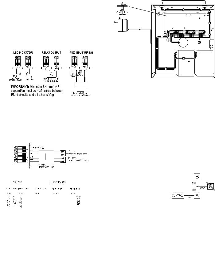
PGM2 is a high current output (300mA) and operates similarly to PGM1. If more than 300 mA of current is required, a relay must be used. Refer to the diagram. PGM2 can also be configured as an input.
A minimum ¼” (6.4mm) separation must be maintained at all points between power limited and non-power limited wiring and connections.
|
|
North America Only |
|
|
|
|
|
|
POWER LIMITED |
|
|
|
|
PC Board |
Stand Off |
|
|
|
|
|
|
|
Cable Tie (not supplied) recommended |
|
|
||
Cabinet |
|
|
|
|
|
|
|
Primary:120VAC/60Hz. |
|
UA503 |
|
|
DSC |
|
PC1616/1832/1864 |
|
|
|||
|
DSCPTD 1640U |
|
|
|||
|
Secondary: 16.5VDC 40VA |
|
|
|
|
|
|
Class II Transformer |
|
WARNING: |
|
|
|
|
NOTE: Do not connect |
|
|
|
|
|
|
High Voltage. Disconnect AC Power |
|
|
|||
|
transformer to receptacle |
and telephone lines before servicing |
|
|
||
|
controlled by a switch |
|
|
|||
|
|
|
|
|
|
|
|
|
|
PC1864 |
PC1864 |
|
|
|
|
|
Only |
PC1832 |
|
|
|
CON1 |
|
|
Only |
|
TB-2 |
|
BAT+BAT- |
|
|
|
|
|
|
|
AUX+ BELL+ |
PGM1 PGM3 |
Z7 COM Z8 EGND |
RING |
R-1 |
|
AC AC |
AUXBELLRED BLK YEL GRN |
PGM2 PGM4 Z1 COM Z2 Z3 COM Z4 Z5 COM Z6 |
TIP |
T-1 |
|
|
12V / 7 AHr |
12V / 7 AHr |
|
BLACK |
|
|
RED |
|
NON-POWER LIMITED |
DSC Model BD7-12 |
|
or equivalent |
|
|
|
|
|
|
Battery |
|
|
StandbyTime: |
|
|
24Hrs min. |
|
NOTE: Wire entry for power limited wiring must be separated by a different entry access from non-power limited wiring.
Zone Input Terminals - Z1 to Z8
Each detection device must be connected to a zone terminal on the system. It is suggested that each zone have one detection device however it is possible to wire multiple detection devices to the same zone.
For zone wiring details, see section 2.10 ’Zone Wiring’ .
Telephone Connection Terminals - TIP,RING,T-1,R-1
If a telephone line is required for central station communication or downloading, connect an RJ-31X jack in the following manner:
Connect the PC1616/PC1832/PC1864 and modules that use the telephone line(s) in the following order:
|
|
|
|
|
|
|
|
|
|
|
|
|
|
|
|
PC1616 |
|
|
|
|
|
|
|
|
|
|
|
PC5900 |
||||||||||||
|
|
|
|
|
|
|
|
|
|
|
|
|
|
|
|
PC18xx |
|
|
|
|
|
|
|
|
|
|
|
|||||||||||||
|
|
|
|
|
|
|
|
|
|
|
|
|
|
|
|
|
|
|
|
|
|
|
|
|
|
|
|
|
|
|
|
|
|
|||||||
|
|
|
|
|
|
|
|
|
|
|
|
|
|
|
|
|
|
|
|
|
|
|
|
|
|
|
|
|
|
|
|
|
|
|
|
|
|
|
|
|
|
|
|
|
|
|
|
|
|
|
|
|
|
|
|
|
|
|
|
|
|
|
|
|
|
|
|
|
|
|
|
|
|
|
|
|
|
|
|
|
|
|
|
|
|
|
|
|
|
|
|
|
|
|
|
|
|
|
|
|
|
|
|
|
|
|
|
|
|
|
|
|
|
|
|
|
|
|
|
|
|
|
|
|
|
|
|
|
|
|
|
|
|
|
|
|
|
|
|
|
|
|
|
|
|
|
|
|
|
|
|
|
|
|
|
|
|
|
|
|
|
|
|
NOTE: Ensure that all plugs and jacks meet the dimension, tolerance and metallic plating requirements of 47 C.F.R. Part 68, SubPart F. For proper operation there must be no other telephone equipment connected between the control panel and the telephone company facilities.
NOTE: Do not connect the alarm panel communicator to telephone lines intended for use with a FAX machine. These lines may incorporate a voice filter which disconnects the line if anything other than FAX signals are detected, resulting in incomplete transmissions.
2.4 Keybus Operation and Wiring
The Keybus is used by the panel to communicate with all modules connected and by the modules to talk to the panel. The RED and BLK terminals are used to provide power while YEL and GRN are clock and data.
The 4 Keybus terminals of the panel must be connected to the 4 Keybus terminals or wires of all modules.
The following conditions apply:
•Keybus should be run with minimum 22 gauge quad (0.5mm), two pair twisted preferred
•The modules can be home run to the panel, connected in series or can be T-tapped
•Any module can be connected anywhere along the Keybus, you do not need a separate Keybus wire run for keypads, zone expanders etc.
•No module can be more than 1,000'/305m (in wire length) from the panel
NOTE: Shielded wire should not be used for Keybus wiring.
Example of Keybus Wiring
Module (A) is wired correctly as it is within 1,000'/305m of
the panel, in wire distance.
Module (B) is wired correctly as it is within 1,000'/305m of the panel, in wire distance.
Module (C) is NOT wired correctly as it is further than
1,000'/305m from the panel, in wire distance.
2.5 Current Ratings - Modules & Accessories
In order for the PC1616/PC1832/PC1864 system to operate properly, the power output capabilities of the main control and expansion devices must not be exceeded. Use the data presented below to ensure that no part of the system is overloaded and cannot function properly.
2.3 Wire Routing for Power & Non-Power Limited
All wiring entry points are designated by the arrows. All circuits are classified UL installation power limited except for the battery leads which are not power limited.
WWW.DIYALARMFORUM.COM
6
PC1616/PC1832/PC1864 Device Ratings
|
|
Max |
Device |
Description |
Rating |
|
|
@12VDC |
|
|
|
PK5500 |
LCD Keypad |
125mA |
|
|
|
PK5501 |
ICON Keypad |
125mA |
|
|
|
PK5508 |
8 Zone LED Keypad |
125mA |
|
|
|
PK5516 |
16 Zone LED Keypad |
125mA |
|
|
|
RFK5500 |
LCD Keypad with Wireless Module |
135mA |
|
|
|
RFK5501 |
ICON Keypad with Wireless Module |
135mA |
|
|
|
RFK5508 |
8 Zone LED Keypad With Wireless |
135mA |
|
Module |
|
|
|
|
RFK5516 |
16 Zone LED Keypad With Wireless |
135mA |
|
Module |
|
|
|
|
LCD5500Z |
LCD Keypad |
85mA |
|
|
|
LCD5501Z |
ICON Keypad |
45mA |
|
|
|
LCD5501Z32-433 |
ICON Keypad with Wireless Module |
260mA |
|
|
|
LCD5511 |
ICON Keypad |
100mA |
|
|
|
LED5511Z |
8 Zone LED Keypad |
100mA |
|
|
|
PC5532Z |
32 Zone LED Keypad |
85mA |
|
|
|
PC5516Z |
16 Zone LED Keypad |
85mA |
|
|
|
PC5508Z |
8 Zone LED Keypad |
85mA |
|
|
|
PC5108 |
Zone Module |
35mA |
|
|
|
PC5132 |
Wireless Module |
125mA |
|
|
|
PC5200 |
Output Module |
20mA |
|
|
|
PC5204 |
Output Module |
20mA |
|
|
|
PC5208 |
Output Module |
50mA |
|
|
|
PC5320 |
Multiple Receiver Interface Module |
55mA |
|
|
|
Escort5580(TC) |
Voice Prompting Module |
150mA |
|
|
|
PC5400 |
Printer Module |
65mA |
|
|
|
PC5401 |
Data Interface Module |
35mA |
|
|
|
PC5700 |
Fire Module |
150mA |
|
|
|
PC5900 |
Audio Verification Module |
50mA |
|
|
|
PC5904 |
Central Station Talk/Listen Module |
175mA |
|
|
|
PC5921 |
Intercom Audio Station |
20mA |
|
|
|
PC5921 EXT |
Door Box Audio Station |
20mA |
|
|
|
PC5921 EXT/R |
Door Box Audio Station |
35mA |
|
|
|
System Output Ratings
Device |
Output |
Rating (12VDC) |
PC1616 |
AUX: |
500mA (700 mA for UL/ULC). |
PC1832 |
|
Subtract the listed rating for each keypad, |
PC1864 |
|
expansion module and accessory connected to |
|
|
AUX or Keybus. |
|
BELL: |
700 mA. Continuous Rating. |
|
|
|
|
|
2.0 A. Short Term. Available only with stand-by |
|
|
battery connected. |
|
|
|
PC5200 |
AUX: |
1.0 A.Continuous Rating. Subtract for each |
|
|
device connected. |
|
|
|
|
|
3.0 A. Short Term. Available only with stand-by |
|
|
battery connected. |
|
|
|
PC5204 |
AUX: |
1.0 A. Continuous Rating. Subtract for each |
|
|
device connected. |
|
|
|
|
|
3.0 A. Short Term. Available only with stand-by |
|
|
battery connected. |
|
|
|
PC5208 |
AUX: |
250 mA. Subtract for each device connected. |
|
|
Subtract the total load on this terminal from the |
|
|
PC1616/PC1832/PC1864 AUX/Keybus output. |
|
|
|
PC5108 |
VAUX: |
100 mA. Subtract for each device connected. |
|
|
Subtract the total load on this terminal from the |
|
|
PC1616/PC1832/PC1864 AUX/Keybus output. |
|
|
|
Other Devices
Read the manufacturer’s literature carefully to determine the maximum current requirement (during activation or alarm) and use this value for loading calculations. Do not allow connected devices to exceed the system capabilities during any possible operational mode.
2.6 Assigning Zones to Zone Expanders
The main panel contains zones 1 to 8. Additional zone expanders may be added to increase the number of zones on the system. Each zone expander consists of one group of 8 zones. Each module must be set to assign the specific zones to the expander. To do this, set the jumpers located on the expander to the proper settings (see chart below).
NOTE: PC5108 v1.0 and lower modules can only support the first 32 zones on the PC1616/PC1832/PC1864 system. PC5108 v1.0 and lower, PC5700 enrolls as two expander modules.
NOTE: Do not use PC5108 v1.0 and v2.0 simultaneously on the same PC1616/PC1832/PC1864 panel.
NOTE: Before a zone expander will work properly, you must set the jumpers so the panel can determine the correct zone assignment.
The following are jumper settings for different zone assignments for PC5108 v2.0 modules. If you need to enroll PC5108 v1.0 or PC5700 modules, refer to the appropriate module Installation Sheet for the correct jumper settings.
|
Module Jumpers |
|
System Zones Assigned |
||
J1 |
|
J2 |
|
J3 |
|
|
|
|
|
|
|
ON |
|
ON |
|
ON |
Zones disabled |
|
|
|
|
|
|
OFF |
|
ON |
|
ON |
Zones 09 - 16 |
|
|
|
|
|
|
ON |
|
OFF |
|
ON |
Zones 17 - 24 |
|
|
|
|
|
|
OFF |
|
OFF |
|
ON |
Zones 25 - 32 |
|
|
|
|
|
|
ON |
|
ON |
|
OFF |
Zones 33 - 40 |
|
|
|
|
|
|
OFF |
|
ON |
|
OFF |
Zones 41 - 48 |
|
|
|
|
|
|
ON |
|
OFF |
|
OFF |
Zones 49 - 56 |
|
|
|
|
|
|
OFF |
|
OFF |
|
OFF |
Zones 57 - 64 |
|
|
|
|
|
|
The following is a diagram of the PC5108 zone expander module and where the jumper switches are located. Refer to the PC5108 Installation Instruction sheet for the module for more information.
NOTE: Only jumpers J1, J2, and J3 determine the zone assignment for the module.
2.7 Keypad Assignment
There are 8 available slots for keypads. LED and ICON keypads by default are assigned to slot 1. LCD keypads are assigned by default to slot 8. Keypads can each be assigned to a different slot (1 to 8) which offers two advantages. The panel can supervise the keypad connection to indicate a trouble condition if it is removed. Also keypads can be assigned to operate on a specific partition, or to operate as a global keypad.
How to Assign Keypads
1.Enter Installer Programming
2.Press [000] for Keypad Programming
3.Press [0] for Partition and Slot Assignment
4.Enter a two digit number to specify the partition and slot assignment.
•1st digit - enter 0 for Global operation, or enter 1-8 for Partitions 1-8
•2nd digit - enter 1 to 8 for Slot Assignment
5.Press the [#] key twice to exit programming.
6.Continue this procedure at each keypad until all have been assigned to the correct slot and partition (see section [902].
WWW.DIYALARMFORUM.COM
7

NOTE: All keypad assignments must be done at each keypad on the system. When using LCD keypads, one keypad must remain in slot 8 to upload/download LCD information. Do not assign more than one keypad to the same slot.
NOTE: The following keypad versions can only be used on the Partition 1 & Partition 2, and the first 8, 16, or 32 zones: PC5508(Z), PC5516(Z), PC5532(Z) versions v2.0 & lower, LCD5500(Z) versions 3.x and lower. To assign a keypad to a slot and select the partition it will operate in, enter the following:
Function Key Programming
Each of the 5 function keys on each keypad may be programmed for different operations.
1.Enter Installer Programming.
2.Press [000] for Keypad Programming.
3.Enter [1] to [5] to select function key to program.
4.Enter a 2-digit number for function key option - [00] - [32].
5.Continue from step 3 until all function keys are programmed.
6.Press [#] key twice to exit Installer Programming.
Keypad Function Keys
[00] - Null |
[10] - Alarm Memory |
[24] - Bypass Group Recall |
|
|
|
[01] - Partition 1 Select |
[11] - User Programming |
[26] - Time & Date Program |
|
|
|
[02] - Partition 2 Select |
[12] - User Functions |
[27] - Partition 3 Select |
|
|
|
[03] - Stay Arm |
[13] - Command Output 1 |
[28] - Partition 4 Select |
|
|
|
[04] - Away Arm |
[14] - Command Output 2 |
[29] - Partition 5 Select |
|
|
|
[05] - No Entry Arm |
[16] - Quick Exit |
[30] - Partition 6 Select |
|
|
|
[06] - Chime On/Off |
[17] - Activate Stay/Away |
[31] - Partition 7 Select |
|
|
|
[07] - System Test |
[19] - Command Output 3 |
[32] - Partition 8 Select |
|
|
|
[08] - Bypass Mode |
[21] - Command Output 4 |
|
|
|
|
[09] - Trouble Display |
[23] - Bypass Recall |
|
|
|
|
For details on the operation of Function Keys, see section
4.3’Function Keys’ .
2.8Confirming Module Supervision
By default, all modules are supervised upon installation. Supervision is enabled at all times so that the panel can indicate a trouble if a module is removed from the system.
To check which modules are currently connected and supervised:
1.Press [*][8][Installer Code] to enter Installer Programming.
2.Press [903] to display Module Supervision Field.
3.On an LCD keypad, use the arrow keys to scroll through the modules the panel has found on the system.
On LED/ICON keypads, zone lights will be turned on according to what modules the panel has found on the system. Refer to the following chart:
Light |
Module/Device |
Light |
Module/Device |
[1] |
Keypad 1 |
[16] |
Zones 57 to 64 |
|
|
|
|
[2] |
Keypad 2 |
[17] |
Wireless Receiver |
|
|
|
|
[3] |
Keypad 3 |
[18] |
PC5208 |
|
|
|
|
[4] |
Keypad 4 |
[19] |
PC5204 |
|
|
|
|
[5] |
Keypad 5 |
[20] |
PC5400 |
|
|
|
|
[6] |
Keypad 6 |
[21] |
PC5900 |
|
|
|
|
[7] |
Keypad 7 |
[22] |
Alternate Communicator |
|
|
|
|
[8] |
Keypad 8 |
[23] |
Future Use |
|
|
|
|
[9] |
Zones 9 to 16 |
[24] |
Escort5580(TC) |
|
|
|
|
[10] |
Zones 17 to 24 |
[25] |
Future Use |
|
|
|
|
[11] |
Zones 25 to 32 |
[26] |
PC520X-1 |
|
|
|
|
[12] |
Zones 33 to 40 |
[27] |
PC520X-2 |
|
|
|
|
[13] |
Zones 41 to 48 |
[28] |
PC520X-3 |
|
|
|
|
[14] |
Zones 49 to 56 |
[29] |
PC520X-4 |
|
|
|
|
[15] |
PC5100 |
|
|
|
|
|
|
If a module is connected but does not show as being present, it may be due to any of the following reasons:
•it is not connected to the Keybus
•there is a Keybus wiring problem
•the module is more than 1,000'/305m from the panel
•the module does not have enough power
•the wireless receiver does not have any devices added
NOTE: Module supervision will not display correctly at an LCD5500Z v2.x and lower keypad.
2.9 Removing Modules
If a module is no longer required on the system, the panel must be told to stop supervising the module. To do this:
1.Power down the panel by removing the backup battery and AC.
2.Remove the module from the Keybus.
3.Power up the panel by connecting the backup battery and AC.
4.Press [*][8][Installer Code] to enter Installer Programming.
5.Press [902] to enable supervision. The panel will automatically search for all modules connected to the system for the next 60 seconds. Do not perform any other operations during this 60 second period.
6.Once the search is complete enter section [903] to confirm that the correct modules are supervised on the system.
2.10Zone Wiring
For a complete description of the operation of all zone types, see section 5.2 ’Basic Programming’ section [001]-[004]. The panel can be programmed to supervise normally closed, End of Line, or Double End of Line loops. Refer to the following sections to study each type of individually supervised zone wiring.
NOTE: Any zone programmed for Fire or 24 Hour Supervisory must be wired with a single End of Line (EOL) resistor regardless of the type of zone wiring supervision selected for the panel (section [013], options [1] and [2]). See Zone Definitions [001]-[004]. If you change the zone supervision options from DEOL to EOL or from NC to DEOL (section [013], options [1] or [2]), power the system down completely, and then power it back up for correct operation.
NOTE: For UL Listed Installations use SEOL or DEOL only. NOTE: Use minimum 22 AWG wire, maximum 18 AWG wire. NOTE: Do not use shielded wire.
NOTE: Wire run resistance shall not exceed 100Ω.
Burglary Zone Wiring Chart
Wire Gauge |
Maximum Wire length to End of Line Resistor |
|
|
24 |
1900 feet / 579 meters |
|
|
22 |
3000 feet / 914 meters |
|
|
20 |
4900 feet / 1493 meters |
|
|
19 |
6200 feet / 1889 meters |
|
|
18 |
7800 feet / 2377 meters |
|
|
Normally Closed (NC) Loops
To enable normally closed loops, program section [013], option [1] to ON.
NOTE: Do not use Normally Closed Loops for UL Listed systems.
ANY Z ANY COM |
ANY Z ANY COM |
TERMINAL TERMINAL |
TERMINAL TERMINAL |
WWW.DIYALARMFORUM.COM
8

The following chart shows zone status under certain conditions for NC Loops:
Loop Resistance |
Loop Status |
|
|
0Ω(shorted wire, loop shorted) |
Secure |
|
|
Infinite (broken wire, loop open) |
Violated |
|
|
Normally Closed Loops . . . . . . . . . . . . . . Section [013], Option [1]
Single End Of Line (EOL) Resistors
To enable panel detection of single end-of-line resistors, program section [013], options [1] and [2] to OFF.
NOTE: This option should be selected if either Normally Closed (NC) or Normally Open (NO) detection devices or contacts are being used.
The following chart shows zone status under certain conditions for SEOL:
Loop Resistance |
Loop Status |
|
|
0Ω(shorted wire, loop shorted) |
Violated |
|
|
5600Ω(contact closed) |
Secure |
|
|
Infinite (broken wire, loop open) |
Violated |
|
|
End of Line Resistors . . . . . . . . . . . . . . . . Section [013], Option [1] Single End of Line Resistors . . . . . . . . . . . Section [013], Option [2]
Double End of Line (DEOL) Resistors
Double End of Line resistors allow the panel to determine if the zone is in alarm, tampered or faulted.
To enable panel detection of double end of line resistors, program section [013], option [1] to OFF and option [2] to ON.
NOTE: If the Double EOL supervision option is enabled, all hardwired zones must be wired for Double EOL resistors, except for Fire and 24 Hour Supervisory zones. Do not use DEOL resistors for Fire zones or 24 Hour Supervisory zones.
NOTE: Do not wire Fire zones to keypad zone terminals if the DEOL supervision option is selected.
NOTE: This option can only be selected if Normally Closed (NC) detection devices or contacts are being used. Only one NC contact can be connected to each zone.
The following chart shows zone status under certain conditions for DEOL:
Loop Resistance |
Loop Status |
|
|
0Ω(shorted wire, loop shorted) |
Fault |
|
|
5600Ω(contact closed) |
Secure |
|
|
Infinite (broken wire, loop open) |
Tamper |
|
|
11200Ω(contact open) |
Violated |
|
|
End-of-Line Resistors . . . . . . . . . . . . . . . . Section [013], Option [1] Double End-of-Line Resistors . . . . . . . . . . Section [013], Option [2]
Fire Zone Wiring - 4-wire Smoke Detectors
All zones defined as Fire (see section 5.2 ’Basic Programming’ ) must be wired according to the following diagram:
For a complete description of how fire zones operate, see section 5.2 ’Basic Programming’ sections [001]-[004] option 07 and 08.
NOTE: Smoke detectors must be latching type. To reset smoke detector, enter [*][7][2].
Compatible 4-Wire Smoke Detectors
Model |
|
Model |
|
|
Model |
FAS-410x |
|
FSA-410xLST |
|
|
FSA-410xRST |
|
|
|
|
|
|
FSA-410xT |
|
FSA-410xR |
|
|
FSA-410xLRST |
|
|
|
|
|
|
FSA-410xS |
|
FSA-410xRT |
|
|
|
|
|
|
|
|
|
FSA-410xST |
|
FSA-410xRS |
|
|
|
|
|
|
|
|
|
For model numbers above: x=A (ULC) |
x=B (UL) x=C (CE) |
||||
|
|
|
|
|
|
Fire Zone Wiring - 2-wire Smoke Detectors
If PGM 2 has been programmed for 2-Wire Smoke Detector connection (see section 5.2 ’Basic Programming’ ) , the detectors must be wired according to the following diagram:
For a complete description of how fire zones operate, see section 5.2 ’Basic Programming’ section [009] option 04.
NOTE: Do not combine models from different manufacturers on the same circuit. Operation may be impaired.
NOTE: Refer to smoke detector installation sheet when positioning detectors.
WWW.DIYALARMFORUM.COM
9
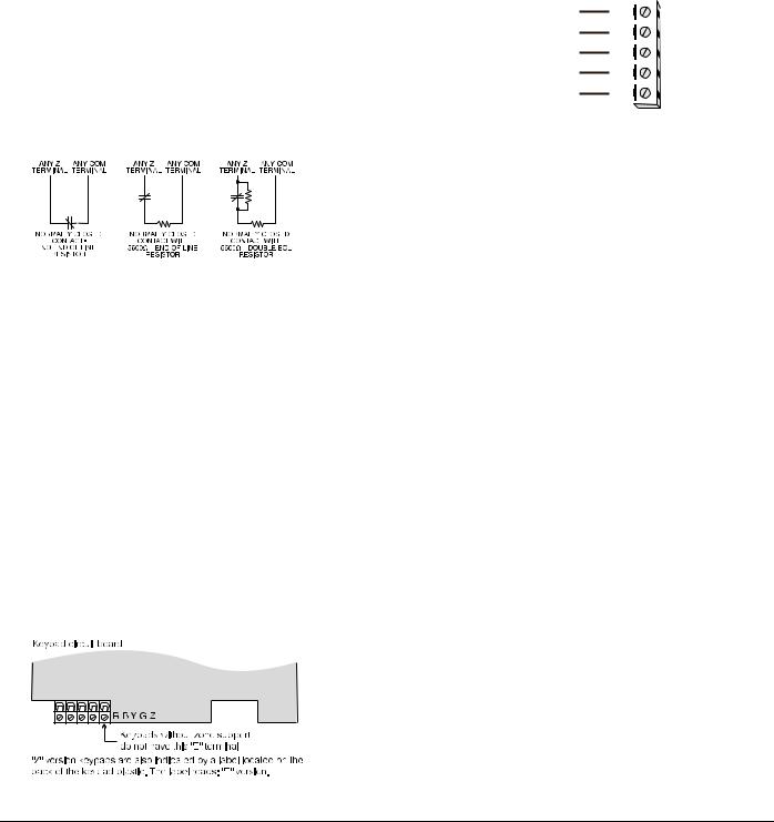
Compatible 2-Wire Smoke Detectors
Model |
|
Model |
|
|
Model |
FAS-210B |
|
FSA-210BLST |
|
|
FSA-210BRST |
|
|
|
|
|
|
FSA-210BT |
|
FSA-210BR |
|
|
FSA-210BLRST |
|
|
|
|
|
|
FSA-210BS |
|
FSA-210BRT |
|
|
|
|
|
|
|
|
|
FSA-210BST |
|
FSA-210BRS |
|
|
|
|
|
|
|
|
|
For model numbers above: x=A (ULC) |
x=B (UL) x=C (CE) |
||||
|
|
|
|
|
|
2-Wire Smoke Detector Initating Circuit
Item |
Specification |
|
|
Style/Class, Supervised, Power Limited |
Style B (Class B) |
|
|
Compatibility Identifier |
PC18-1 |
|
|
DC Output Voltage |
9.8-13.8 VDC |
|
|
Detector Load |
2mA (MAX) |
|
|
Single End of Line Resistor (SEOL) |
2200Ω |
|
|
Loop Resistance |
24Ω(MAX) |
|
|
Standby Impedance |
1020Ω(NOM) |
Alarm Impedance |
570Ω(MAX) |
|
|
Alarm Current |
89mA (MAX) |
|
|
Keyswitch Zone Wiring
Zones may be programmed to be used as keyswitch arming zones and must be wired according to the following diagram:
For a complete description of how keyswitch zones operate, see section 5.2 ’Basic Programming’ sections [001]-[004] option 22 and 23.
2.11 Keypad Zone/PGM
Keypads with zone inputs can be connected to devices such as door contacts. This saves you from running wires back to the control panel for every device.
To install the keypad, open the keypad plastic. Refer to the Installation Sheet that came with the keypad for instructions on how to open the keypad. Locate the terminals on the keypad circuit board. Connect the four Keybus wires from the control panel: the red wire to R, the black to B, the yellow to Y and the green to G.
LCD55XXZ
To connect the zone input on an LCD55XXZ keypad, run one wire to the Z terminal and the other to B. For powered devices, use red and black to supply power to the device. Run the red wire to the R (positive) terminal and the black wire to the B (negative) terminal.
When using end of line supervision, connect the zone according to one of the configurations outlined in section 2.10 ‘Zone Wiring‘ on page 8.
NOTE: LCD55XXZ zones do not support DEOL resistors.
LCD55XXZ
PK55XX/RFK55XX
PK55XX/RFK55XX keypad comes with a Z/P terminal. This terminal can be configured as an input (zone) or output (PGM).
To connect the zone input on a PK55XX/RFK55XX keypad, run one wire to the Z/P terminal and the other to B. For powered devices, use red and black to supply power to the device. Run the red wire to the R (positive) terminal and the black wire to the B (negative) terminal. The PK55XX/ RFK55XX keypad zone supports Normaly Closed Loops, Single End of Line and Double End of Line.
To connect the PGM output on a PK55XX/RFK55XX keypad, run one wire to the Z/P terminal and the other to R.
PK55XX/RFK55XX
|
PK55xx |
|
RED |
R |
|
|
||
BLK |
B |
|
YEL |
Y |
|
GRN |
G |
|
To zone or |
Z/P |
|
PGM output |
|
|
|
|
NOTE: End of line resistors must be placed on the device end of the loop, not at the keypad.
Assigning Keypad Zones
When using keypad zone inputs, each input used must be assigned a zone number in Installer’s Programming.
First, ensure that you have enrolled all installed keypads into the desired slots (see section 2.7 ’Keypad Assignment’ ) to assign the keypad to a slot.
Next, enter programming section [020] to assign the zones. There are eight programming locations in this section, one for each keypad slot. Enter a 2-digit zone number for each of the keypad zones. This number must be entered in the location corresponding to the keypad to which each zone is connected.
NOTE: If a keypad zone input is assigned to zone number 1 to 8, the corresponding zone cannot be used on the main control panel.
Once the keypad zones are assigned, you must also program zone definitions and zone attributes (see Section 5.2 Basic Programming PWS Sect 3 [001]-[004] and Section 5.3 Advanced System Programming PWS Sect 4 [101]-[164]).
2.12 Zone Activity Log
This feature stores the date stamp of each zone activation event. It stores the last day, month and year a zone was violated. This data can be retrieved during the installer’s DLS access.
NOTE: If the panel is powered down, this data will be lost.
WWW.DIYALARMFORUM.COM
10
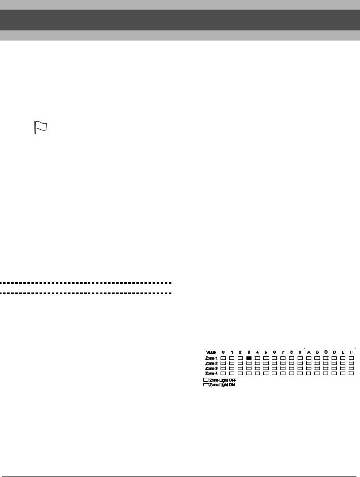
Section 3: How to Program
The following section of the manual describes how to enter Installer Programming and how to program the various sections.
NOTE: It is extremely important that you read the following section of the manual to completely understand how to program the panel.
3.1 How to Enter Installer Programming |
NOTE: It is important to watch the Ready light. If the |
|||||||||||||||||||||||||||||||||||||||||||||||||||||
Installer Programming is used to program all communicator |
light is flashing any number you enter will be pro- |
|||||||||||||||||||||||||||||||||||||||||||||||||||||
and panel options. The Installer Code is [5555] at default, |
grammed as the HEX equivalent. |
|||||||||||||||||||||||||||||||||||||||||||||||||||||
but should be changed to prevent unauthorized access to |
Example: To enter ‘C1’ for a closing by user 1, you would |
|||||||||||||||||||||||||||||||||||||||||||||||||||||
programming. |
enter [*] [3] [*], [1] |
|||||||||||||||||||||||||||||||||||||||||||||||||||||
NOTE: Once the Installer’s Mode is exited, the system will |
[*] to enter Hexadecimal mode (Ready light flashes) |
|||||||||||||||||||||||||||||||||||||||||||||||||||||
reset. This will take 15 seconds. Do not attempt to per- |
[3] to enter C |
|||||||||||||||||||||||||||||||||||||||||||||||||||||
form any system function during this reset period. In addi- |
[*] to return to decimal mode (Ready light is solid) |
|||||||||||||||||||||||||||||||||||||||||||||||||||||
tion, all outputs will return to their normal, deactivated |
[1] to enter digit 1 |
|||||||||||||||||||||||||||||||||||||||||||||||||||||
state (or activated if inverted). |
If you enter information into a section and make a mistake, |
|||||||||||||||||||||||||||||||||||||||||||||||||||||
|
|
|
press the [#] key to exit the section. Select that section again |
|||||||||||||||||||||||||||||||||||||||||||||||||||
NOTE: |
EN |
EN installations will restrict access to the Mas- |
and re-enter the information correctly. |
|||||||||||||||||||||||||||||||||||||||||||||||||||
|
If you are using a pulse communications format, a decimal |
|||||||||||||||||||||||||||||||||||||||||||||||||||||
ter code section [007] in installers programming. The |
||||||||||||||||||||||||||||||||||||||||||||||||||||||
zero [0] does not transmit. Programming a zero [0] tells the |
||||||||||||||||||||||||||||||||||||||||||||||||||||||
Installer may view the Master Code via DLS. |
||||||||||||||||||||||||||||||||||||||||||||||||||||||
panel not to send any pulses for that digit. Decimal zero [0] is |
||||||||||||||||||||||||||||||||||||||||||||||||||||||
LED Keypad |
||||||||||||||||||||||||||||||||||||||||||||||||||||||
a filler digit. To make a zero [0] transmit, it must be pro- |
||||||||||||||||||||||||||||||||||||||||||||||||||||||
Step 1: From any keypad enter [*][8][Installer Code]. |
grammed as a Hexadecimal ‘A’. |
|||||||||||||||||||||||||||||||||||||||||||||||||||||
• The ‘Program’ light will flash to indicate you are in pro- |
Example: for the three digit account number ‘403’, you would |
|||||||||||||||||||||||||||||||||||||||||||||||||||||
gramming |
enter [4], [*] [1] [*] [3], [0]. |
|||||||||||||||||||||||||||||||||||||||||||||||||||||
• The ‘Armed’ light will turn on to indicate the panel is |
[4] to enter the digit 4 |
|||||||||||||||||||||||||||||||||||||||||||||||||||||
waiting for the 3 digit Section number to program |
[*] to enter Hexadecimal mode (Ready light flashes) |
|||||||||||||||||||||||||||||||||||||||||||||||||||||
Step 2: Enter the 3 digit Section number you want to pro- |
[1] to enter A |
|||||||||||||||||||||||||||||||||||||||||||||||||||||
gram. |
|
|
[*] to return to decimal mode (Ready light is solid) |
|||||||||||||||||||||||||||||||||||||||||||||||||||
• The Armed light will turn off |
[3] to enter the digit 3 |
|||||||||||||||||||||||||||||||||||||||||||||||||||||
• The Ready light will turn on to indicate the panel is ready |
[0] to enter the digit 0 as a filler digit. |
|||||||||||||||||||||||||||||||||||||||||||||||||||||
for the information for the selected Section |
3.4 Programming Toggle Options |
|||||||||||||||||||||||||||||||||||||||||||||||||||||
NOTE: If the 3 digit section number entered is not valid or |
||||||||||||||||||||||||||||||||||||||||||||||||||||||
Some Sections contain several toggle options. The panel will |
||||||||||||||||||||||||||||||||||||||||||||||||||||||
the module that pertains to the Section is not present, the |
||||||||||||||||||||||||||||||||||||||||||||||||||||||
use zone lights 1 through 8 to indicate if the different options |
||||||||||||||||||||||||||||||||||||||||||||||||||||||
keypad will sound a 2 second error tone. |
||||||||||||||||||||||||||||||||||||||||||||||||||||||
are enabled or disabled. Refer to the Programming Work- |
||||||||||||||||||||||||||||||||||||||||||||||||||||||
LCD Keypad |
||||||||||||||||||||||||||||||||||||||||||||||||||||||
sheets to determine what each option represents and |
||||||||||||||||||||||||||||||||||||||||||||||||||||||
Step 1: From any keypad enter [*][8][Installer Code]. |
whether the light should be ON or OFF for your application. |
|||||||||||||||||||||||||||||||||||||||||||||||||||||
The Keypad will display ‘Enter Section’ followed by three |
Press the number corresponding to the option to toggle the |
|||||||||||||||||||||||||||||||||||||||||||||||||||||
dashes. |
|
|
light ON or OFF. |
|||||||||||||||||||||||||||||||||||||||||||||||||||
Step 2: Enter the 3 digit Section number you want to pro- |
Once all the toggle options have been selected correctly |
|||||||||||||||||||||||||||||||||||||||||||||||||||||
gram. The keypad will now display information for the section |
press the [#] key to exit the Section and save the changes. |
|||||||||||||||||||||||||||||||||||||||||||||||||||||
entered. |
|
|
The panel will turn off the Ready light and turn on the Armed |
|||||||||||||||||||||||||||||||||||||||||||||||||||
Installer Code |
. . . . . . . . . . . . . . . . . . . . . . . . . . . . . . Section [006] |
light. |
||||||||||||||||||||||||||||||||||||||||||||||||||||
3.5 Viewing Programming |
||||||||||||||||||||||||||||||||||||||||||||||||||||||
|
|
|
||||||||||||||||||||||||||||||||||||||||||||||||||||
3.2 Programming Decimal Data |
LED and ICON Keypads |
|||||||||||||||||||||||||||||||||||||||||||||||||||||
When the Ready light is ON the panel is waiting for the infor- |
Any programming section can be viewed from an LED or |
|||||||||||||||||||||||||||||||||||||||||||||||||||||
mation to be programmed for the selected Section. Enter the |
ICON keypad. When a programming section is entered, the |
|||||||||||||||||||||||||||||||||||||||||||||||||||||
information written in the boxes for the Section found in the |
keypad will immediately display the first digit of information |
|||||||||||||||||||||||||||||||||||||||||||||||||||||
Programming Worksheets. |
programmed in that section. |
|||||||||||||||||||||||||||||||||||||||||||||||||||||
If a digit is entered for each program box in a Section the |
The keypad displays the information using a binary format, |
|||||||||||||||||||||||||||||||||||||||||||||||||||||
panel will automatically exit from the Section. It will turn OFF |
according to the following chart: |
|||||||||||||||||||||||||||||||||||||||||||||||||||||
the Ready light and turn the Armed light back ON. |
|
|
|
|
|
|
|
|
|
|
|
See Hex data entry instructions |
||||||||||||||||||||||||||||||||||||||||||
You can also press the [#] key to exit a Section before enter- |
|
|
|
|
|
|
|
|
|
|
|
|
|
|
|
|
|
|
|
|
|
|
|
|
|
|
|
|
|
|
|
|
|
|
|
|
|
|
|
|
|
|
|
|
|
|
|
|
|
|
|
|||
|
|
|
|
|
|
|
|
|
|
|
|
|
|
|
|
|
|
|
|
|
|
|
|
|
|
|
|
|
|
|
|
|
|
|
|
|
|
|
|
|
|
|
|
|
|
|
|
|
|
|
||||
ing data for every box. This is handy if you only need to |
|
|
|
|
|
|
|
|
|
|
|
|
|
|
|
|
|
|
|
|
|
|
|
|
|
|
|
|
|
|
|
|
|
|
|
|
|
|
|
|
|
|
|
|
|
|
|
|
|
|
|
|||
|
|
|
|
|
|
|
|
|
|
|
|
|
|
|
|
|
|
|
|
|
|
|
|
|
|
|
|
|
|
|
|
|
|
|
|
|
|
|
|
|
|
|
|
|
|
|
|
|
|
|
||||
|
|
|
|
|
|
|
|
|
|
|
|
|
|
|
|
|
|
|
|
|
|
|
|
|
|
|
|
|
|
|
|
|
|
|
|
|
|
|
|
|
|
|
|
|
|
|
|
|
|
|
||||
change the first few program boxes. All other locations in the |
|
|
|
|
|
|
|
|
|
|
|
|
|
|
|
|
|
|
|
|
|
|
|
|
|
|
|
|
|
|
|
|
|
|
|
|
|
|
|
|
|
|
|
|
|
|
|
|
|
|
|
|||
|
|
|
|
|
|
|
|
|
|
|
|
|
|
|
|
|
|
|
|
|
|
|
|
|
|
|
|
|
|
|
|
|
|
|
|
|
|
|
|
|
|
|
|
|
|
|
|
|
|
|
||||
Section will remain unchanged. If the [#] key is pressed the |
|
|
|
|
|
|
|
|
|
|
|
|
|
|
|
|
|
|
|
|
|
|
|
|
|
|
|
|
|
|
|
|
|
|
|
|
|
|
|
|
|
|
|
|
|
|
|
|
|
|
|
|||
|
|
|
|
|
|
|
|
|
|
|
|
|
|
|
|
|
|
|
|
|
|
|
|
|
|
|
|
|
|
|
|
|
|
|
|
|
|
|
|
|
|
|
|
|
|
|
|
|
|
|
||||
|
|
|
|
|
|
|
|
|
|
|
|
|
|
|
|
|
|
|
|
|
|
|
|
|
|
|
|
|
|
|
|
|
|
|
|
|
|
|
|
|
|
|
|
|
|
|
|
|
|
|
||||
panel will turn OFF the Ready light, turn ON the Armed light |
|
|
|
|
|
|
|
|
|
|
|
|
|
|
|
|
|
|
|
|
|
|
|
|
|
|
|
|
|
|
|
|
|
|
|
|
|
|
|
|
|
|
|
|
|
|
|
|
|
|
|
|||
|
|
|
|
|
|
|
|
|
|
|
|
|
|
|
|
|
|
|
|
|
|
|
|
|
|
|
|
|
|
|
|
|
|
|
|
|
|
|
|
|
|
|
|
|
|
|
|
|
|
|
||||
and exit you from the Section. |
|
|
|
|
|
|
|
|
|
|
|
|
|
|
|
|
|
|
|
|
|
|
|
|
|
|
|
|
|
|
|
|
|
|
|
|
|
|
|
|
|
|
|
|
|
|
|
|
|
|
|
|||
3.3 Programming Hexadecimal Data |
|
|
|
|
|
|
|
|
|
|
|
|
|
|
|
|
|
|
|
|
|
|
|
|
|
|
|
|
|
|
|
|
|
|
|
|
|
|
|
|
|
|
|
|
|
|
|
|
|
|
|
|||
Press any of the Emergency Keys (Fire, Auxiliary or Panic) |
||||||||||||||||||||||||||||||||||||||||||||||||||||||
On occasion, hexadecimal (HEX) digits may be required. To |
||||||||||||||||||||||||||||||||||||||||||||||||||||||
to advance to the next digit. |
||||||||||||||||||||||||||||||||||||||||||||||||||||||
program a HEX digit press the [*] key. The panel will enter |
||||||||||||||||||||||||||||||||||||||||||||||||||||||
When all the digits in a section have been viewed, the panel |
||||||||||||||||||||||||||||||||||||||||||||||||||||||
HEX programming and Ready light will begin to flash. |
||||||||||||||||||||||||||||||||||||||||||||||||||||||
will exit the section: the Ready Light will turn OFF, and the |
||||||||||||||||||||||||||||||||||||||||||||||||||||||
The following table indicates which number should be |
||||||||||||||||||||||||||||||||||||||||||||||||||||||
Armed light will turn ON, waiting for the next three-digit pro- |
||||||||||||||||||||||||||||||||||||||||||||||||||||||
pressed to enter the corresponding HEX digit: |
||||||||||||||||||||||||||||||||||||||||||||||||||||||
gramming section number to be entered. |
||||||||||||||||||||||||||||||||||||||||||||||||||||||
1 = A 2 = B 3 = C 4 = D 5 = E 6 = F |
||||||||||||||||||||||||||||||||||||||||||||||||||||||
Press the [#] key to exit the section. |
||||||||||||||||||||||||||||||||||||||||||||||||||||||
After the correct HEX digit is entered the Ready light will |
||||||||||||||||||||||||||||||||||||||||||||||||||||||
LCD Keypad |
||||||||||||||||||||||||||||||||||||||||||||||||||||||
continue to flash. If another HEX digit is required press the |
||||||||||||||||||||||||||||||||||||||||||||||||||||||
corresponding number. If a decimal digit is required press |
When a programming section is entered, the keypad will |
|||||||||||||||||||||||||||||||||||||||||||||||||||||
the [*] key again. The Ready light will turn on solid and the |
immediately display all the information programmed in that |
|||||||||||||||||||||||||||||||||||||||||||||||||||||
panel will return to regular decimal programming. |
section. Use the arrow keys (< >) to scroll through the data |
|||||||||||||||||||||||||||||||||||||||||||||||||||||
being displayed. To exit the section, scroll past the end of the data displayed, or press the [#] key.
WWW.DIYALARMFORUM.COM
11

Section 4: Keypad Commands
Use any system keypad to enter commands, or to program the PC1616/PC1832/PC1864 security system. The LED keypad uses function and zone indicator lights to represent alarm functions and status. The LCD keypad provides a written description on the liquid crystal display and uses function indicator lights to communicate alarm status to the user. The PC1616/PC1832/PC1864 User’s Guide provides basic directions for arming and disarming the system, bypassing zones and performing user functions from the keypads. The following sections provide additional details on these functions.
4.1Arming and Disarming
Arming
The system cannot be armed unless the ‘Ready’ light is on. If the ‘Ready’ light is not on, ensure all protected doors and windows are secure and stop movement in areas covered by motion detectors.
When the ‘Ready’ light is on, enter a valid access code. As each digit is pressed the keypad will beep. If an incorrect code is entered, the keypad will emit a steady 2 second beep to indicate that the code was not correct. If the code is correct but the ‘Ready’ light was not on, the panel will beep six times rapidly followed by a long two second beep to indicate the system was not ready.
When the correct code is entered and the system is ready, the panel beeps six times rapidly, and the ‘Armed’ light turns on. The panel begins counting down the exit delay. If the Audible Exit Delay option is enabled, the keypad will beep every second until the exit delay expires. The keypad will beep rapidly for the last 10 seconds of exit delay to warn the user the system is about to arm. Exit the premises through the designated entry/exit door before the exit delay expires.
Users can restart the exit delay while it is counting down by pressing the Away key. The system will not log the user who re-started the exit delay, unless the Quick Arming Disabled/Function Keys Require Code option is turned on (section [015], option [4]).
NOTE: If the system has been Stay armed, or armed with no entry delay ([*][9]), pressing the Away key will not restart an exit delay.
NOTE: If the system is armed while an alarm is in memory, the mode cannot be changed.
Other methods of arming are available (See section “[*][0] Quick Arm”, “[*][9] Arming without Entry Delay”, and section 4.4 “Function Keys”).
NOTE: The PC1616/PC1832/PC1864 has a built-in feature called Audible Exit Fault (see Section [013], option 6 for more information).
NOTE: For SKAFOR Installations, the keypad will sound a steady tone for 5 seconds when the system is armed while a trouble is present. Exit delay should continue normally (silent or audible) after 5 seconds.
Stay and Away Arming
When a user arms the system with an access code, if any zones on the system have been programmed as Stay/Away, the panel will immediately turn on the ‘Bypass’ light. The panel will then monitor all zones programmed as Delay 1 and Delay 2. If no delay type zone is violated by the end of the exit delay (e.g. nobody leaves through the entry/exit door), the panel will bypass all Stay/Away type zones. The panel is now “Stay” armed. The ‘Bypass’ light will remain on to inform the home owner that the interior protection is bypassed. This is a convenience for users that want to arm the panel while at home. Using this method, users do not have to bypass the interior zones manually.
Users can add Stay/Away zones back into the system at any time by entering [*][1] (see section ’[*][1] Zone Bypassing’ ), or by using the Away button.
If a delay zone is violated during the exit delay (e.g. somebody leaves through the designated entry/exit door), all zones will be active after the exit delay expires. The panel is now “Away” armed. The Bypass light on the keypad will be off. Other methods of Stay and Away arming are available (see section 4.3 ’Function Keys’ ).
NOTE: The buzzer will not sound during “Stay Arming”.
Stay Arming
When a user arms the system by pressing the Stay button, if any zones on the system have been programmed as Stay/ Away, the panel will immediately turn on the ‘Bypass’ light. After the exit delay the panel will bypass all Stay/Away type zones. The panel is now “Stay” armed. The ‘Bypass’ light will remain on to inform the home owner that the interior protection is bypassed. This is a convenience for users that want to arm the panel while at home. Using this method, users do not have to bypass the interior zones manually.
Users can add Stay/Away zones back into the system at any time by entering [*][1] (see section ’[*][1] Zone Bypassing’ ), or by using the Away button.
Away Arming
When a user arms the system by pressing the Away button, the panel will begin the exit delay. All zones will be active after the exit delay expires. The panel is now “Away” armed. The Bypass light on the keypad will be off.
Using the Away Button While Stay Armed
If a partition is armed in Stay mode and a user wishes to leave the premises without having to disarm and re-arm the system, they may press the Away button. The system will begin counting the standard exit delay, allowing the user to leave without actually disarming. The panel will log “Armed in Away Mode” upon completion of the Exit Delay. This feature is useful for users with Wireless Keys with Stay/Away buttons, and who wish to have their panel armed at all times.
Using the Stay Button While Away Armed
Pressing the Stay key while a partition is Away armed will begin the Exit Delay again. The panel will log “Armed in Stay Mode”. This feature is useful for users with Wireless Keys with Stay/Away buttons, and who wish to have their panel armed at all times.
NOTE: If Function Keys require the entering of an access code, a valid access code must be entered to toggle between arming modes. The access code used to perform this function will be logged with “User Log User XX”. Swinger Shutdown will be reset if the Away button is pressed while the system is armed.
Inhibit Arming EN
EN
All troubles on the panel will prevent the system from arming and it will force the Ready LED to shut off. Press [9] in the Trouble Menu to clear Troubles.
NOTE: With this feature disabled, Bell Trouble will still inhibit arming.
WWW.DIYALARMFORUM.COM
12

Disarming
To disarm the panel, enter the premises through the designated entry/exit door. The keypad will emit a steady beep to warn that you must disarm the system. During the last 10 seconds of entry delay the panel will pulse the keypad beeper on and off rapidly to warn the entry delay is about to expire.
Enter a valid Access Code at the keypad. If an error is made, re-enter the code correctly. When a correct code is entered the keypad will turn off the ‘Armed’ light and stop the keypad buzzer.
If an alarm occurred while the panel was armed the ‘Memory’ light and the zones which caused the alarm will be flashing. Press the [#] key to return the keypad to the Ready state.
Event Buffer (Event Log)
The panel will store the last 500 events that have occurred on the system. Each event will contain the time, date, partition and the event itself along with the zone number, access code number or any other information pertaining to the event.
If the Event Buffer Follows Swinger Shutdown feature is enabled (Section [013], option 7) the event buffer will not store events after the swinger shutdown level has been reached. This will prevent the panel from overwriting the entire buffer if a problem exists. The event buffer can be viewed three different ways. It can be viewed through an LCD keypad, printed on-site using the PC5400 printer module or it can be uploaded through the DLS software.
Viewing the Event Buffer
The following is the procedure for viewing the event buffer through the LCD keypad:
•Step 1 - Enter [*] [6] [Master/Access Code]
•Step 2 - Select ‘View Event Buffer’
The keypad will display the Event Number, Partition, Time and Date of the event in question. Use the [*] key to toggle between this information and the event itself. Use the arrow keys (< >) to scroll through the events in the buffer. When you have finished viewing the event buffer press the [#] key to exit.
NOTE: When viewing events for partitions 3 to 8 on an LCD5500 v2.x and lower keypad, they will show as being logged in the “System Area”.
4.2 [*] Commands
[*][1] Zone Bypassing
Users can bypass individual zones using the [*][1] keypad command. This command can be used if users want to have access to an area while the Partition is armed, or to bypass a defective zone (bad contact, damaged wiring) until service can be provided.
A bypassed zone will not cause an alarm.
When the partition is disarmed, all zones that were bypassed using [*][1] will be unbypassed, except for 24-hr zones.
If the Code Required for Bypass option is enabled, an access code will be required to enter the Bypass mode. Only access codes with the Bypass attribute enabled will be able to bypass zones (see section ’[*][5] Programming Access Codes’ ).
Bypassing Zones with an LCD keypad:
Start with disarming the system.
1.Press [*] to enter the function menu. The keypad will display “Press [*] for < > Zone Bypass”.
2.Press [1] or [*], then your [access code] (if required). The keypad will display “Zone Search < > Zone Name”.
3.Enter the two-digit number of the zone(s) to be bypassed (01-64). You can also use the < > keys to find the zone to be bypassed, and then press [*] to select the zone.
The keypad will display “Zone Search < > “Zone Name?”. “B” will appear on the display to show that the zone is bypassed. If a zone is open (e.g., door with door contact is open), the keypad will display “Zone Search < > “Zone Name” O”. If you bypass the open zone, a “B” will replace the “O”.
4.To unbypass a zone, enter the two-digit number of the zone(s) to be bypassed (01-64). You can also use the < > keys to find the zone, and then press [*] to select the zone. The “B” will disappear from the display to show that the zone is no longer bypassed.
5.To exit bypassing mode and return to the Ready state, press [#].
Bypassing Zones with a LED/ICON keypad:
Start with disarming the system
1.Press [*][1], then your [access code] (if required).
2.Enter the two-digit number of the zone(s) to be bypassed (01-64). On LED keypads, the zone light will turn on to indicate that the zone is bypassed.
3.To unbypass a zone, enter the two-digit number of the zone (01-64). On LED keypads,the zone light will turn off to indicate that the zone is not bypassed.
4.To exit bypassing mode and return to the Ready state, press [#].
Other Bypass Features:
The following features are also available on the [*][1] zone bypassing menu:
• Bypass Recall: Press [99] while in the [*][1] menu to recall the last set of bypassed zones.
•Clear Bypasses: Press [00] while in the [*][1] menu to clear all bypassed zones.
•Bypass Groups: Users can program a group of zones to be bypassed (bypass group). Each partition can have a different bypass group. To program a bypass group, in the [*][1] menu, select the zones to be bypassed. Press
[95]to save the group. To recall the group, press [*][1] followed by [91].
If the Code Required for Bypass option is enabled, the Master code or Supervisor codes must be used to access this feature.
NOTE: The zone attribute for zone bypassing must be enabled (see Section [101]-[164] Zone Attributes, Option 4).
NOTE: Hold-up zones should not be part of Bypass Groups.
NOTE: A zone that is manually bypassed via [*][1] will bypass the alarm, fault, and tamper conditions when DEOL is used.
NOTE: If a 24-hour zone is bypassed, ensure that the zone is restored or disabled before removing the bypass.
Code required for bypass . . . . . . . . . . . . . Section [015], Option [5]
[*][2] Trouble Display
The panel constantly monitors itself for several different trouble conditions. If a trouble condition is present, the Trouble light will be ON and the keypad will beep twice every 10 seconds. The trouble beep can be silenced by pressing any key on any keypad. If Bell Squawk on Trouble is enabled (section [014], option[5]), the bell will squawk every 10 seconds when a trouble condition is present.
NOTE: If there is an AC trouble, the keypad will not beep for a General System Trouble.
To view trouble conditions from an LED or ICON keypad:
1.Press [*][2] to enter the trouble menu.
2.The keypad will flash the Trouble light. The zone indicator lights corresponding to the present trouble conditions will be ON.
WWW.DIYALARMFORUM.COM
13

.
Light |
Trouble |
|
|
|
|
|
|
||||
Light [1] |
Service Required: Press [1] to determine the specific trouble. Lights 1 - 8 will light up to indicate the trouble: |
||||
|
• |
Light [1] |
Low Battery: Main panel backup battery charge is low (below 11.5 volts under load).Trouble is restored when the battery charges over |
||
|
|
12.5 volts. |
|
|
|
|
• |
Light [2] |
Bell Circuit Trouble: The bell circuit is open (see section 2.2 ’Terminal Descriptions’ ). |
||
|
• |
Light [3] |
General System Trouble: One or more of the following troubles has occurred: the PC5204 Power Supply module has an AUX failure, |
||
|
|
PC5204 Output #1 Trouble, Home Automation Trouble on the Escort5580(TC), or a printer connected to the PC5400 Printer module has a fault and |
|||
|
|
is off-line, or T-Link Troubles. Users can view specific conditions in the Event Buffer. |
|||
|
• |
Light [4] |
General System Tamper: Tamper has been detected from a module. |
||
|
• |
Light [5] |
General System Supervisory: The panel has lost communication with a module connected to the Keybus (See section 2.8 ‘Confirming |
||
|
|
Module Supervision‘ on page 8). The event buffer will log the event. |
|||
|
• |
Light [6] |
RF Jam: Please refer to the PC5132 Installation Manual for more information. |
||
|
• |
Light [7] |
PC5204 Low Battery: The PC5204 module has a low backup battery. |
||
|
• |
Light [8] |
PC5204 AC Failure: The PC5204 module has lost AC power. |
||
|
NOTE: If you remove and then restore power to the main panel in order to service any PC5204 module, or any module being powered by a |
||||
|
PC5204, you must also remove and then restore power to the PC5204 and any connected modules. This ensures that any troubles present |
||||
|
on the module are correctly logged and/or annunciated. |
||||
|
|
||||
Light [2] |
AC Failure: AC power is no longer being supplied to the control panel. The Trouble light will flash if an AC Failure is present, if the Trouble Light |
||||
|
Flashes if AC Fails option is programmed (section [016], option [2]). This trouble will not be displayed if the AC Trouble Displayed option is disabled |
||||
|
(section [016], option [1]). |
|
|||
|
|
||||
Light [3] |
Telephone Line Monitoring Trouble (TLM): There is a problem with the telephone line. If the system has an Alternate Communicator, this trouble |
||||
|
can be reported to the central station by programming reporting codes in sections [345] and [346]. |
||||
|
|
||||
Light [4] |
Failure to Communicate (FTC): The communicator failed to communicate with any of the programmed telephone numbers (see section 5.6 ‘Com- |
||||
|
municator Programming’). |
|
|||
|
|
||||
Light [5] |
Zone Fault (including Fire Zone): A zone on the system is experiencing trouble, meaning that a zone could not provide an alarm to the panel if |
||||
|
required to do so (e.g. a fire zone is open, or there is a short on a DEOL zone, or a supervisory fault on a wireless zone). When a zone fault occurs, |
||||
|
the keypad(s) on the system will start to beep. Press [5] while in Trouble mode to view the affected zones. |
||||
|
NOTE: A Fire zone trouble will be generated and displayed in the armed state. |
||||
|
|
||||
Light [6] |
Zone Tamper: A zone configured for Double End Of Line resistor supervision has a tamper condition, or the tamper switch is open on a wireless |
||||
|
device. When a tamper condition occurs, the keypad(s) will start to beep (if the system is armed, an alarm will occur). Press [6] while in the Trouble |
||||
|
mode to view the affected zones. If a zone is tampered or faulted, it must be fully restored to clear the trouble. |
||||
|
|
||||
Light [7] |
Device Low Battery/RF Delinquency: A wireless device has a low battery condition. Press [7] one, two, or three times to view which devices are |
||||
|
experiencing battery failure. Press the [7] key an additional time to view zones in RF Delinquency trouble. An LED keypad will indicate battery failure |
||||
|
using zone lights. The following will occur: |
|
|||
|
|
|
|
Keypad beeps: |
Keypad displays: |
|
Press [7] |
|
1 |
Zones with low batteries (LED keypad - zone lights 1 to 32) |
|
|
Press [7] again |
2 |
Handheld keypads with low batteries (LED keypad - zone lights 1 to 4) |
||
|
Press [7] again |
3 |
Wireless keys with low batteries (LED keypad - zone lights 1 to 16) |
||
|
Press [7] again |
4 |
Zones in RF Delinquency trouble (LED keypad - zone lights 1 to 32) |
||
|
|
||||
Light [8] |
Loss of System Time: When the panel is powered up, the internal clock needs to be set to the correct time. This trouble is cleared when an attempt |
||||
|
is made to reset the clock. This is set in [*][6] [Master Code] Programming on page 16. |
||||
|
|
|
|
|
|
Trouble Menu Acknowledgement  EN
EN
Press [9] for Trouble Menu Acknowledgement. This will acknowledge and override existing troubles so the system can be armed. An override event will also be generated and logged, identifying the user. To override open zones, use the Zone Bypass feature [*][1].
If a zone fault/tamper occurs, press [*][2][9] to override the trouble, then [*][1] to override the open zone.
NOTE: When using the Trouble Menu Acknowledgement feature, Section [022] Option 3 has to be enabled.
When using an LCD keypad, the trouble conditions will be listed on the display. Users can scroll through the list of present trouble conditions using the arrow (< >) keys.
NOTE: Troubles can be viewed while armed using the LCD keypad, provided the keypad is version 2.0 or later. Older keypads will incorrectly display “Fire Trouble”. If using older LCD keypads, program section [013], option [3] as OFF to ensure that troubles are displayed correctly.
NOTE: If a trouble is present when the system is armed, the trouble LED will remain on during Exit Delay but will turn off once the exit delay timer expires.
[*][3] Alarm Memory
The ‘Memory’ light will be on if any alarm occurred during the last armed period or if an alarm occurred while the panel was disarmed (24 hour zones). Press [*][3] to view zones in alarm memory. To clear the memory, arm and disarm the system.
[*][4] Door Chime On/Off
If enabled the keypad will beep 6 times rapidly when a zone is tripped and restored. The panel will only do this for zones with the Door Chime attribute enabled and if the door chime feature is enabled. The door chime attribute for each zone is programmed in sections [101] to [164].
[*][5] Programming Access Codes
Access codes are required in order to perform various functions on the system such as arm, disarm, activate command outputs etc.
Program New Access Code
To program an access code enter [*][5][Master Code] followed by a two digit number corresponding to the access code you want to program, then enter a new access code.
The available access codes are as follows:
General Access Codes - Access Codes [01] to [32]
Each access code can be used to arm and disarm the assigned partitions. Additional access code attributes are also programmable to determine what abilities the code will have. You can program partition assignments and access code attributes by following the instructions in this section.
Supervisor Codes - Access Codes [41] and [42]
Supervisor Codes can program additional access codes. By default, Supervisor codes have the same partition and attribute programming as the Master code. You can change the partition and attribute programming for these codes by following the instructions in this section.
WWW.DIYALARMFORUM.COM
14
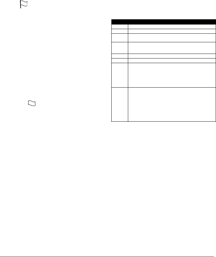
System Master Code - Access Code [40]
By default the System Master Code is enabled to operate on all partitions and can perform any keypad function. This code can be used to program all access codes, including the Supervisor Codes and Duress Codes.
If the Master Code Not Changeable option is enabled the System Master Code can only be changed using Installer Programming.
NOTE: EN For EN installations the installer will not have
access to Master Code Programming. In order to return the master code to the factory default setting enter the Special Installer Function [989][Installer's Code][989] (Master Code Factory Default Programming). This will allow the installer to default the Master Code.
Duress Codes - Access Codes [33] and [34]
Duress codes are standard user codes that will transmit the Duress Reporting Code whenever the code is entered to perform any function on the system.
NOTE: Duress codes are not valid when entering [*][5], [*][6] or [*][8] sections.
NOTE: Duress codes cannot be programmed as a duplicate of another code or as a “Code + 1”.
Maintenance Code
The maintenance code can only be used to arm and disarm the system. It cannot be used to bypass zones, to access the Escort5580(TC), or to cancel or postpone automatic arming. The code can only be programmed in Installer’s Programming. The Maintenance code cannot bypass zones, use [*][9] to arm the system, cancel auto-arming, or perform [*][7] command functions. There will be no arm/disarm bell squawks when the Maintenance code is used.
Guard Code C
C
The Guard Code can arm the panel at any time. However, the Guard code can only disarm the system after an alarm, tamper, fault or trouble condition has occurred. It can also be used to bypass zones and activate Command Outputs. The Guard Code may be programmed in Section [008].
Arming and disarming using the Guard Code will log as "Closing (Opening) by Maintenance Code". If a Command Output that requires a code is activated with the Guard Code, no User Log will be made. When zones are bypassed with the Guard Code, the panel will log "[*][1] Access by User".
NOTE: The Latching Trouble feature should be used with the Guard Code feature in order disarm with Trouble Present.
Partition Assignments and Access Code Attributes
You can enable or disable each access code to work on each partition. Additional access code attributes are also programmable. Attributes determine what abilities the code will have.
By default, each code has the attributes of the code used to program it. For example, if you use the Master code to program other access codes, the new codes will have the same attributes as the Master code. You can change the partition and attribute programming by following the instructions described below.
You cannot change Master code partition or attribute programming. The Master code has all partitions and all attributes turned on, except for the Bell Squawk on Arming/ Disarming and One Time Use Code Attributes.
Access Code Partition Assignment
To program which partition(s) each code will work on:
1.Enter [*][5][Master Code][8] for partition programming.
2.Enter the 2-digit number of the access code you want to edit.
3. Enter the partition number (1-8) to toggle it on or off.
NOTE: Partition programming is NOT supported by the following keypads: PC5508(Z), PC5516(Z), PC5532(Z) versions v2.00 and lower; LCD5500(Z) version 2.x and lower; LCD5501Z version 1.x and lower.
Access Code Attributes
To program each attribute:
1.Enter [*][5][Master Code][9] for attribute programming.
2.Enter the 2-digit number of the access code you want to edit.
3.Enter the attribute number to toggle it on or off.
Programmable Attributes
Attribute Description
[1]For Future Use
[2]For Future Use
[3]Zone Bypass enabled.
This attribute allows the user to bypass zones.
[4]Escort5580(TC) Remote Access
This attribute allows the user to access the security system via the Escort, if installed.
[5]For Future Use
[6]For Future Use
[7]Bell Squawk on Arming/Disarming. When this attribute is ON, the bell will squawk when the access code is entered to arm or disarm the system. For example, you can use the arm/disarm bell squawk attribute to have wireless key access codes squawk the bell, while other codes are silent. To do this, enable attribute [7] on all access codes associated with wireless keys.
[8]One Time Use Code. This attribute will only affect Access Codes 01-16. If the panel is disarmed with this code, the code will be erased at the end of the Exit Delay the next time that the panel is armed, regardless of which code is used to arm the system. The code will also be erased at the end of the Exit Delay when used to arm the panel. If the panel is disarmed during the Exit Delay when armed with a One Time Use Code, it will still be valid after the next time the panel is armed (unless the same One Time Code is used to arm the second time).
NOTE: If you enable the Bell Squawk on Arming/Disarming option (section [014], option [1]), the bell will sound arm/ disarm bell squawks for all access codes, regardless of the programming for attribute [7] (see Section 5.3 Basic Programming PWS Sect 3 [001]-[004] (see Section 5.4 ‘Advanced Programming’).
Installer’s Programming - Codes and Options
There are three codes which can be programmed by the installer in Installer’s Programming: the Installer’s code,
Master Code and a Maintenance Code/Guard Code. All other access codes can be programmed through the [*][5] command, as described previously in this section.
The master code can also be programmed by the user as access code (40). However, if the Master Code Not Changeable option is enabled, the master code can only be accessed in Installer’s Programming.
General access codes can arm and disarm the system. When the Code Required for Bypassing option is enabled, users will need to enter a valid access code in order to bypass zones. Individual access codes can have the Zone Bypassing attribute disabled under Access Code Attribute programming, as described previously in this section.
If the 6-Digit User Access Codes option is enabled, all the access codes are programmed with six digits instead of four. The Installer’s Code will become [555555]. If 4-digit codes are already programmed and this option is selected, the first four digits of the programmed codes will remain as programmed and the last two digits will be [00].
If the 4-Digit User Access Codes is selected, all codes will be 4-Digits in length, with the exception of the Panel ID code and the Downloading Access Code. If 6-digit codes were
WWW.DIYALARMFORUM.COM
15

previously programmed and this option is enabled, the first four digits of each code will be used.
Installer’s Code . . . . . . . . . . . . . . . . . . . . . . . . . . . . . Section [006] Maintenance Code . . . . . . . . . . . . . . . . . . . . . . . . . . Section [008] Master Code Not Changeable . . . . . . . . . . . . . . . Section [015]: [6] Code Required for Bypassing . . . . . . . . . . . . . . . Section [015]: [5] 6-digit User Access Codes . . . . . . . . . . . . . . . . . . Section [701]: [5]
NOTE: Only one keypad at a time can use [*][5] programming.
[*][6] User Functions
NOTE: Only one keypad at a time can use [*][6] programming.
To program user functions, perform the following:
1.Press [*][6][Master Code]. The keypad will flash the ‘Program’ light.
2.Press the number [1] to [8] for the item to be programmed.
•[1] - Time and Date
Enter 4 digits for 24 Hour System Time (HH-MM). Valid entries are 00-23 for the hour and 00-59 for minutes. Enter 6 digits for the Month, Day and Year (MM-DD-YY)
•[2] - Auto-arm Enable/Disable
Pressing [2] while in the User Function menu will enable auto-arm (3 beeps) or disable auto-arm (one long beep). The auto-arm feature needs to be enabled on each partition individualy. With this feature enabled, the panel will automatically arm in the Away mode (Stay Away zones active) at the scheduled time. The auto-arm time is programmed with the [*][6][Master Code][3] command.
•[3] - Auto-arm Schedule
Enter [3] to change the Auto-arm time for each day of the week. Scroll to the day of the week you want to change, or enter the number of the day (1-7 for Sunday to Saturday). On an LED keypad, zone lights 1-7 will represent Sunday to Saturday.
When you have selected a day, enter the Auto-arm time in 24-hour format (i.e. enter a 4-digit number in [hhmm] format).
The system will return you to the day selection menu. Scroll to the next day you want to program, or to exit auto-arm programming, press [#].
NOTE: To change the auto-arm schedule at another partition, users with access to that partition will have to select the partition on the keypad before entering the auto-arm schedule menu.
NOTE: Only LCD5500 v2.0 or greater keypads support the [*][6][3] menu option.
•[4] - System Test
When System test is initiated the panel will perform the following.
-Sound the alarm output for two seconds
-Light all lights and display pixels on the keypad
-Sound the keypad buzzer for two seconds
-Test the main panel/PC5200/PC5204 battery
-Send a System Test Reporting code, if programmed.
•[5] - Enable DLS / Allow System Service
If enabled, the installer will be able to access Installer Programming by DLS. In case of DLS access this provides a window where rings will be detected by the panel. The DLS window will remain open for 6hrs, during which time the installer will be able to enter DLS an unlimited number of times. After the 6-hr window has expired, Installer’s Programming will be unavailable again until the window is re-opened.
•[6] - User Initiated Call-Up
When [6] is pressed, the panel will initiate a call to the
downloading computer. The panel will make 1 attempt to call the downloading computer.
NOTE: The downloading computer must be waiting for the panel to call before downloading can be performed.
•[7] - For Future Use
•[8] - User Walk Test EN
EN
[*][6] User Functions allows the user to enable/disable the User Walk Test mode. The User Walk Test functionality and operation are based on the Installer Walk Test however there are some relevant differences between them regarding fire zone violation handling or communication during the test. Fire zones, [F] Key and 2-wire Smoke Detectors are excluded from User Walk Test. If any of these zones is violated or activated during User Walk Test, the system will exit from Walk Test mode and generate an alarm condition for the violated fire zone. To provide support for event communication new Programming Sections are added for the Walk Test Begin/End reporting codes.
The User Walk Test mode operates with a 15 minute time out. If there is no zone violation for 15 minutes, the system restores from User Walk Test mode.
The Bell will sound a squawk instead of a 2-second pulse.
LCD Keypad User Functions
Additional features are available using on the LCD keypad. These features do not have numbers assigned. Use the arrow keys (< >) to scroll through the [ ][6] menu and press the [ ] key to select the following commands.
•View Event Buffer: The 500 Event Buffer can be viewed through any LCD keypad.
•Brightness Control: When this option is selected the keypad will allow you to scroll through 10 different backlight level options. Use the arrow keys (<>) to scroll to the desired backlight level and press the [#] key to exit.
•Contrast Control: When this option is selected the keypad will allow you to scroll through 10 different contrast level options. Use the arrow keys (< >) to scroll to the desired contrast level and press the [#] key to exit.
•Keypad Buzzer Control: When this option is selected the keypad will allow you to scroll through 21 different keypad sounder tone options. Use the arrow keys (< >) to scroll to the desired keypad beeper level and press the [#] key to exit. This function can be achieved on LED keypads by holding the [*] key.
[*][7] Command Output Functions
There are four output functions available to the user. Entering [*][7] [1-4] [Access Code, if required] will activate any output programmed as [19]-[22] (respectively). Each function can be performed when the system is either armed or disarmed.
[*][8] Installer Programming
Enter [*][8] followed by the Installer Code to enter Installer Programming.
[*][9] Arming Without Entry Delay
When a partition is armed with the [*][9] command the panel will remove the entry delay from the partition. After the exit delay, Delay 1 and Delay 2 type zones will behave as instant and Stay/Away zones will remain bypassed. The entry delay can be activated or deactivated at any time while the system is armed by pressing [*][9].
NOTE: If the panel is armed using [*][9], disarming will only be possible from the keypad inside the premises.
NOTE: Global Delay zones will always have an entry delay, even if the system is armed using [*][9].
WWW.DIYALARMFORUM.COM
16
[*][0] Quick Arm
If the Quick Arm Enable option is enabled the panel can be armed by entering [*][0]. This is a useful method of arming a Partition when someone without a access code will be required to arm a Partition.
NOTE: The Quick Arm feature must be enabled in order for the Stay/Away function keys to operate as intended. If the feature is not enabled, the user will be required to enter their access code after pressing the Stay or Away function key in order to arm the system in the stay or away mode.
[*][0] Quick Exit
Quick Exit will allow someone to leave an armed premise through a Delay type zone without having to disarm and rearm the system.
When [*][0] is entered, if the Quick Exit Enabled option is enabled, the panel will provide a two minute window to exit. During this time the panel will ignore the first activation of a Delay type zone. When the Delay zone is secured the panel will end the two minute time period.
If a second Delay zone is tripped, or if the zone is not restored after two minutes, the panel will start entry delay.
NOTE: If Quick Exit is used on a partitioned system, Keypad Blanking and Access Code Required to Remove Blanking should be enabled.
Quick Arm Enable . . . . . . . . . . . . . . . . . . Section [015], Option [4] Quick Exit Enable. . . . . . . . . . . . . . . . . . . Section [015], Option [3]
4.3 Function Keys
There are 5 function keys on the PC1616/PC1832/PC1864 keypads. The function is activated by pressing and holding the key for 2 seconds. The programming of any function key on any keypad may be changed to one of the options listed below. (See section 2.7 ‘Keypad Assignment‘ on page 7 for instructions on changing function key programming.)
[00] - Null Key
The key is not used and will perform no function when pressed.
[01] - Select Partition 1
Provides an easy way to select Partition 1. This is the same as pressing and holding the [#] key then pressing and holding the [1] key to select Partition 1 (see section 4.4 ’Global and Partition Keypad Operation’ ).
[02] - Select Partition 2
Provides an easy way to select Partition 2. This is the same as pressing and holding the [#] key then pressing and holding the [2] key to select Partition 2 (see section 4.4 ’Global and Partition Keypad Operation’ ).
[03] - Stay Arm
Arms the partition to which the keypad is assigned. All Stay/ Away type zones will be automatically bypassed. Delay type zones will provide entry and exit delay. The Quick Arm feature must be enabled for this key to function (Section [015], Option [4]). If Quick Arming is not enabled, the user must enter their access code after pressing the function key in order to arm the system in the Stay mode.
[04] - Away Arm
Arms the partition to which the keypad is assigned. All Stay/ Away type zones will be active at the end of the exit delay. Delay type zones will provide entry and exit delay. The Quick Arm feature must be enabled for this key to function (Section [015], Option [4]). If Quick Arming is not enabled, the user must enter their access code after pressing the function key in order to arm the system in the Away mode.
[05] - [*]+[9] No-Entry Delay Arm
After this function key is pressed the user must enter a valid access code. The Partition will arm and remove entry delay
from the partition when the exit delay expires (see section ’[*][9] Arming Without Entry Delay’ ).
[06] - [*]+[4] Door Chime On/Off
Pressing the key will toggle the Door Chime feature ON or OFF. One solid beep means the feature has been disabled, three short beeps means it has been enabled.
[07] - [*]+[6]...[4] System Test
This function key provides the user with a simple method for testing the system (see section ’[*][6] User Functions’ ). A valid Master Code is required to perform this command.
[08] - [*]+[1] Bypass Mode
This function key provides the user with a simple method for entering the Bypass Mode. If a access code is required it must be entered before bypassing can be performed (see section ’[*][1] Zone Bypassing’ ).
[09] - [*]+[2] Trouble Display
This function key provides the user with a simple method for entering the Trouble Display Mode (see section ’[*][2] Trouble Display’ ).
[10] - [*]+[3] Alarm Memory
This function key provides the user with a simple method for entering the Alarm Memory Display Mode (see section ’[*][3] Alarm Memory’ ).
[11] - [*]+[5] Programming Access Codes
This function key provides the user with a simple method for programming access codes. After this key is pressed a valid System Master or Supervisor Code will have to be entered before the panel will allow programming to be performed (see section ’[*][5] Programming Access Codes’ ).
[12] - [*]+[6] User Functions
This function key provides the user with an easy method for programming user functions. After keys are pressed a valid System Master or Partition Master must be entered before the panel will allow user functions to be performed (see section ’[*][6] User Functions’ ).
[13] - [*]+[7]+[1] Command Output Option 1
This function key provides the user with a simple method for activating a PGM Output programmed as Command Output Option 1 (See Section 5.8 Programmable Output Programming PWS Sect 8). By default, after this key is pressed a valid access code must be entered (see section ’[*][7] Command Output Functions’ ).
[14] - [*]+[7]+[2] Smoke Detector Reset
Pressing this key will cause the panel to activate for 5 seconds any output programmed as Sensor Reset. (see section ’[*][7] Command Output Functions’ ).
[15]- For Future Use
[16]- [*]+[0] Quick Exit
Pressing this key will cause the panel to activate the Quick Exit feature (see section ’[*][0] Quick Exit’ ).
[17] - [*]+[1] Reactivate Stay/Away Zones
This function key provides the user with a simple method for adding Stay/Away zones back into the system (see section ’[*][1] Zone Bypassing’ ).
[18]- For Future Use
[19]- [*]+[7]+[3] Command Output 3
This function key provides the user with a simple method for activating a PGM Output programmed as Command Output Option 3
WWW.DIYALARMFORUM.COM
17
 Loading...