

Page 1
Medical Air Compressor
Operating Instructions
MT-763-90a
Page 2

NOTICE
Proprietary Information
This document contains information in which Dräger Medical, Inc.
claimed proprietary rights. The information may not be reproduced in
whole or in part except as authorized in writing by Dräger. This information is the property of Dräger Medical, Inc., it is provided solely for the
use intended.
Repairs/Modifications
Repairs on this device shall be performed only by Dräger Service or its
Authorized Service Centers. Information about repairs can be obtained
from Dräger or Authorized Dealers. Dräger Medical, Inc. will not be
responsible for injury to persons or damage to property arising directly or
indirectly out of unauthorized repairs or modifications to this device.
Furthermore, any unauthorized repairs or modifications void any warranty
extended by Dräger.
This document is provided for your information only. It will not be
exchanged or updated without request.
Trademarks
The Dräger name and logo are registered trademarks of
Drägerwerk Aktiengesellschaft, Lübeck, Germany
Dräger Medizintechnik GmbH,1998
All rights reserved, Subject to modifications
Page 3

Contents
Contents
Important Safety Information READ THIS FIRST........4
Operator's Responsibility for Patient Safety..................4
Limitation of Liability..................................................... 4
Warranty......................................................................5
Definitions.................................................................... 6
General WARNINGS and CAUTIONS......................... 6
Precautions During Preparation.................................... 7
Precautions During Care.............................................. 7
Precautions During Maintenance.................................. 8
Precautions During Installation......................................8
Intended Use.............................................................. 9
Preparation................................................................10
Before First Use......................................................... 10
Connecting Compressor............................................ 10
Standby Mode (Option).............................................. 11
Operation.................................................................. 12
Standby Mode............................................................12
Switching Off............................................................. 12
Care...........................................................................13
Wipe Disinfection....................................................... 13
Installation Procedures............................................. 20
Installing Compressor On the Ventilator Cart or
Standalone cart.......................................................... 22
Installing the Power Cord........................................... 23
Preventive Maintenance Procedures........................ 24
Removing the Filter Assembly.....................................24
Changing the Prefilter.................................................25
Changing the Main Filter.............................................25
Changing the Intake Filter...........................................27
Installing the Filter Assembly.......................................28
Replacing a Fuse........................................................28
Ordering Information................................................ 29
Index......................................................................... 30
Maintenance..............................................................14
Preventive Maintenance Intervals................................ 14
Troubleshooting........................................................15
What's What.............................................................. 16
Technical Data.......................................................... 17
Ambient Conditions.................................................... 17
Performance Characteristics...................................... 17
Operating Characteristics...........................................18
Theory of Operation..................................................19
Operating Instructions Medical Air Compressor
3
Page 4

Important Safety Information
Operator's Responsibility for Patient Safety
Limitation of Liability
Important Safety Information
Operator's Responsibility for Patient Safety
For correct and effective use of the product and in
order to avoid hazards it is mandatory to carefully
read and to observe all portions of this manual.
The design of this device, accompanying literature, and
the labeling on the equipment, take into consideration
that the purchase and use of the equipment are
restricted to trained professionals, and that certain
inherent characteristics of the equipment are known to
the trained operator. Instructions, warnings, and
caution statements are limited, therefore, largely to the
specifics of the Dräger design. This publication
excludes references to various hazards which are
obvious to a medical professional and operator of
respiratory care equipment, to the consequences of
misuse of such equipment, and to potentially adverse
effects in patients with abnormal conditions. Product
modification or misuse can be dangerous.
Dräger Medical, Inc. disclaims all liability for the consequences of product alterations or modifications, as well
as for the consequences which might result from uses
of the product not covered by its intended use or from
the combination of this product with other products
whether supplied by Dräger or by other manufacturers
if such a combination is not endorsed by
Dräger Medical, Inc.
Limitation of Liability
Dräger Medical, Inc.'s liability, whether arising out of or
related to manufacture and sale of the goods, their installation, demonstration, sales representation, use,
performance, or otherwise, including any liability based
upon Dräger Medical, Inc.'s Product Warranty, is subject to and limited to the exclusive terms and conditions
as set forth, whether based upon breach of warranty or
any other cause of action whatsoever, regardless of
any fault attributable to Dräger Medical, Inc. and
regardless of the form of action (including, without limitation, breach of warranty, negligence, strict liability, or
otherwise).
THE STATED EXPRESSED WARRANTlES ARE IN
LlEU OF ALL OTHER WARRANTIES, EXPRESSED
OR IMPLIED, INCLUDING, WITHOUT LIMITATION,
WARRANTlES OF MERCHANTABILITY, FITNESS
FOR ANY PARTICULAR PURPOSE, OR
NONINFRINGEMENT.
Dräger Medical, Inc. shall not be liable for, nor shall
buyer be entitled to recover any special incidental, or
consequential damages or for any liability incurred by
buyer to any third party in any way arising out of or
relating to the goods.
The operators of ventilator systems must recognize
their responsibility for choosing appropriate and reliable
electrical and gas supplies for the support of all systems. Backups for the supplies and alarm functions in
case of a supply failure are mandatory while using lifesupporting ventilators. Patient safety may be achieved
through a wide variety of different means ranging from
electronic surveillance of equipment performance and
patient condition to simple, direct observation of clinical
signs. The responsibility for the selection of the best
level of patient monitoring lies solely with the equipment
operator.
4
Operating Instructions Medical Air Compressor
Page 5

Valid for US and Canada
Warranty
Important Safety Information
Warranty
All Dräger products are guaranteed to be free of
defects for a period of one year from date of delivery.
The following are exceptions to this warranty:
1. The defect shall be a result of workmanship or
material. Defects caused by misuse, mishandling,
tampering, or by modifications not authorized by
Dräger Medical, Inc. or its representatives are not
covered.
2. Rubber and plastic components and materials are
warranted to be free of defects at time of delivery.
3. Oxygen sensors capsules have a six-month limited
warranty from the date of delivery.
Any product which proves to be defective in workmanship or material will be replaced, credited, or repaired
with Dräger Medical, Inc. holding the option.
Dräger Medical, Inc. is not responsible for deterioration,
wear, or abuse. In any case, Dräger Medical, Inc. will not
be liable beyond the original selling price.
Application of this warranty is subject to the following
conditions:
1. Dräger Medical, Inc. or its authorized representative must be promptly notified, in writing, upon
detection of the defective material or equipment.
2. Defective material or equipment must be returned,
shipping prepaid, to Dräger or its authorized
representative.
3. Examination by Dräger Medical, Inc. or its authorized representative must confirm that the defect is
covered by the terms of this warranty.
4. Notification in writing of defective material or equipment must be received by Dräger Medical, Inc. or
its authorized representative no later than two (2)
weeks following expiration of this warranty.
The above is the sole warranty provided by
Dräger Medical, Inc. No other warranty expressed or
implied is intended. Representatives of Dräger are not
authorized to modify the terms of this warranty.
Dräger Medical, Inc., Telford, PA
Operating Instructions Medical Air Compressor
5
Page 6

Important Safety Information
Definitions
General WARNINGS and CAUTIONS
Definitions
WARNING !
A WARNING statement refers to conditions
with a possibility of personal injury if disregarded.
CAUTION !
A CAUTION statement designates the possibility
of damage to equipment if disregarded.
NOTE: A NOTE provides additional information
intended to avoid inconveniences during operation.
Inspection = examination of actual condition
Service = measures to maintain specified
condition
Repair = measures to restore specified
condition
Maintenance = inspection, service, and repair,
where necessary
General WARNINGS and CAUTIONS
WARNING !
Strictly follow Operator's Instruction Manual!
Use of the compressor requires full under-
standing and strict observation of all portions
of these instructions. The equipment is only to
be used for the purpose specified under
"Intended Use" (page 9). Observe all
WARNINGS and CAUTIONS as rendered
throughout this manual and on labels on the
equipment.
WARNING !
DANGER, risk of explosion if used in the
presence of flammable anesthetics.
The equipment is neither approved nor certified for use in areas where combustible or
explosive gas mixtures are likely.
WARNING !
Do not spray flammable liquids near the
compressor. Fire hazard!
Preventive = Maintenance measures at regular
Maintenance intervals
Typing conventions in this manual
Controls are designated as »Control Name«, e.g. »NNNN«
WARNING !
Air supply to life-supporting ventilators:
If the compressor is used to supply air to life-
supporting ventilators, an adequate alternative
supply of medical air must be ensured in case
of a malfunction of the compressor!
Life-supporting ventilators supplied with air
from the compressor must be equipped with a
alarm function that is activated if the supply
pressure drops too low!
Operating Instructions Medical Air Compressor
CAUTION !
Accessories
Use only accessories listed in the Ordering
Information (page 29).
6
Page 7

Important Safety Information
Precautions During Preparation
Precautions During Care
Precautions During Preparation
WARNING !
Installation of the Medical Air Compressor
may be performed by factory trained service
personnel only. Follow installation procedures
on pages 20 to 23 of this manual.
WARNING !
To maintain grounding integrity, connect only
to a "hospital grade" power outlet. Always
disconnect supply before servicing.
CAUTION !
The medical air compressor must not be started
up before it has been properly installed on a
mobile cart.
The compressor unit may be damaged as a
result of poor air circulation if disregarded!
Precautions During Care
CAUTION !
The compressor housing consist of materials that
are sensitive to certain organic solvents sometimes used for cleaning and disinfecting
(e.g., phenols, halogen releasing compounds,
oxygen releasing compounds, strong organic
acids, etc.). Exposure to such substances may
cause damage that is not always immediately
apparent.
CAUTION !
Follow all accepted hospital procedures for
disinfecting parts contaminated by body fluids
(protective clothing, eyewear, etc.).
CAUTION !
Do not connect more than one ventilator to the
compressor!
Compressor overload may result.
CAUTION !
Do not operate compressor in salty air, as this
may cause the non-return valves in the
compressor to corrode.
Operating Instructions Medical Air Compressor
7
Page 8

Important Safety Information
Precautions During Maintenance
Precautions During Installation
Precautions During Maintenance
WARNING !
To avoid any risk of infection, clean and disinfect compressor and accessories before any
maintenance according to established hospital
procedures - this applies also when returning
compressors or parts for repair.
WARNING !
To avoid the risk of an electrical shock always
disconnect from power supply before
servicing.
WARNING !
Preventive Maintenance work on the Dräger
Medical Air Compressor may be performed by
factory trained and authorized personnel only.
CAUTION !
Maintenance
In case of malfunction of this device, contact
your local Dräger Service or our Factory
Authorized Technical Service Center.
The device must be inspected and serviced
(preventive maintenance) by factory trained and
authorized technical service representatives at
regular intervals. A record must be kept on this
preventive maintenance. We recommend
obtaining a service contract through your vendor.
Maintenance or repair of Dräger Medical Air
Compressors shall be performed only by Dräger
authorized technical service representatives.
Precautions During Installation
WARNING !
Installation of the Medical Air Compressor
may be performed by factory trained and
authorized service personnel only.
WARNING !
To avoid risk of electric shock, verify that
compressor is disconnected from line power.
CAUTION !
The transport braces must always be removed
before using the compressor, otherwise major
vibrations may develop in the compressor,
damaging the compressor unit!
CAUTION !
The internal transport braces must be installed
whenever the compressor is transported without
its cart, otherwise the rubber feet of the compressor unit may be damaged.
CAUTION !
Restriction of Distribution
Federal Law and Regulations in the United
States and Canada restrict this device to sale by
or on the order of an physician.
8
Operating Instructions Medical Air Compressor
Page 9

Intended Use
Air compressor supplying compressed air for medical
ventilators.
WARNING !
DANGER, risk of explosion if used in the
presence of flammable anesthetics.
The equipment is neither approved nor certified for use in areas where combustible or
explosive gas mixtures are likely.
WARNING !
Do not spray flammable liquids near the
compressor. Fire hazard!
Intended Use
WARNING !
Air supply to life-supporting ventilators:
If the compressor is used to supply air to life-
supporting ventilators, an adequate alternative
supply of medical air must be ensured in case
of a malfunction of the compressor!
Life-supporting ventilators supplied with air
from the compressor must be equipped with a
alarm function that is activated if the supply
pressure drops too low!
CAUTION !
Accessories
Use only accessories listed in the Ordering
Information (page 29).
Operating Instructions Medical Air Compressor
9
Page 10
Preparation
Before First Use
Connecting Compressor
Preparation
Before First Use
The compressor is supplied without cart. It can be
installed on the ventilator cart (eg. EvitaMobil) or on its
own standalone cart.
CAUTION !
The medical air compressor must not be started
up before it has been properly installed on a
mobile cart.
The compressor unit may be damaged as a
result of poor air circulation if disregarded!
WARNING !
Installation of the Medical Air Compressor
may be performed by factory trained and
authorized service personnel only. Follow
installation procedures on pages 20 to 23 of
this manual.
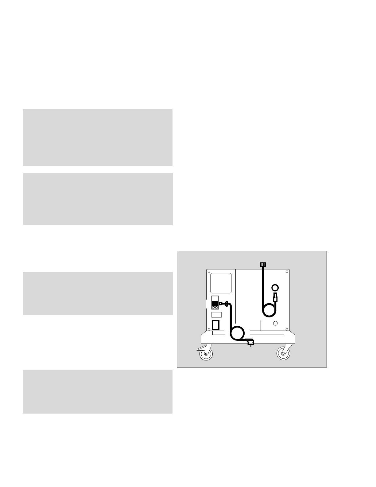
Connecting Compressor
1 Check that the operating voltage specified on the
rating plate matches the line voltage.
WARNING !
To maintain grounding integrity, connect only
to a "hospital grade" power outlet. Always
disconnect supply before servicing.
4 Plug the connector into a grounded outlet socket;
do not use an adapter ("cheater plug").
5 Screw DISS pressure hose connector to the ventilator
»Air « inlet port.
CAUTION !
Do not connect more than one ventilator to the
compressor!
Compressor overload may result.
5
2
6
3
1
4
Operating Instructions Medical Air Compressor
02129080
6 Firmly insert the connector on the pressure hose into
the quick-connect coupling on the compressor - until
it engages.
10
Page 11

● Place the compressor in a cool place, away from
radiators and other sources of heat.
Ensure that air can circulate freely around the
compressor.
CAUTION !
Do not operate compressor in salty air, as this
may cause the non-return valves in the
compressor to corrode.
Standby Mode (Option)
For emergency supply if the hospital's medical air system
fails.
Preparation
Connecting Compressor
1 Screw the pressure hose to the compressor inlet port.
2 Plug quick-connect adapter into wall outlet of the
medical air pipeline system.
1
2
02229080
Operating Instructions Medical Air Compressor
11
Page 12

Operation
Standby Mod
Switching Off
e
Operation
If the compressor has been stored at temperatures below
3 °C (38 °F):
● Wait approx. 2 hours for the compressor to warm up.
1 Press main switch on the rear.
3
02329080
2 The green LED » NN
NN
« in the front of the top cover will
light up = ON.
● Switch ventilator on now.
Refer to "Troubleshooting" on page 15 in the event of
fault conditions.
Standby Mode (Option)
For backup air supply if the hospital's medical air system
fails.
● Always leave the main switch ON .
● Green power status LED » NN
compressor top remains lit.
While switched on, the compressor continuously
monitors pressure in the central medical air system.
If the pressure drops below 40-5 psi (2,7-0,3 bar), the
compressor will automatically supply medical air to the
ventilator to which it is connected. The compressor
switches off its supply and remains on standby when the
pressure in the medical air pipeline system returns and
rises above 50 psi (3,4 bar).
NN
« in the right front of the
4
01029080
Operating Instructions Medical Air Compressor
Switching Off
After switching off the ventilator:
● Press main switch on the rear.
● Green power status LED » NN
NOTE: The compressor is vented automatically.
12
NN
« goes out = OFF.
Page 13

Care
If the filter mat is soiled:
1 Remove filter mat, shake out any dirt and insert mat
again.
● Wipe off any dirt on the compressor housing with a
disposable cloth.
Care
Wipe Disinfection
1
02429080
Wipe Disinfection
CAUTION !
The compressor housing consist of materials that
are sensitive to certain organic solvents sometimes used for cleaning and disinfecting
(e.g., phenols, halogen releasing compounds,
oxygen releasing compounds, strong organic
acids, etc.). Exposure to such substances may
cause damage that is not always immediately
apparent.
CAUTION !
Follow all accepted hospital procedures for disinfecting parts contaminated by body fluids (protective clothing, eyewear, etc.).
To prevent any damage, we recommend that only detergents and disinfectants are used that are compatible with
the materials used in the compressor and its accessories,
e.g. surface disinfectants on the basis of aldehydes,
alcohol, or quarternary ammonia compounds for
disinfection of the main unit.
Ensure that all disinfectants are registered with the U.S.
Environmental Protection Agency for use as intended.
● Wipe compressor housing, hoses and cable with
disinfectant. Always follow the instruction labels
specifically with respect to prescribed concentrations
and the necessary exposure times.
Operating Instructions Medical Air Compressor
13
Page 14

Maintenance
Preventive Maintenance Intervals
Maintenance
WARNING !
To avoid any risk of infection, clean and disinfect compressor and accessories before any
maintenance according to established hospital
procedures - this applies also when returning
compressors or parts for repair.
WARNING !
Always disconnect from power supply before
servicing.
WARNING !
Preventive Maintenance work on the Dräger
Medical Air Compressor may be performed by
factory trained and authorized personnel only.
CAUTION !
Maintenance
In case of malfunction of this device, contact
your local Dräger Service or our Factory
Authorized Technical Service Center.
The device must be inspected and serviced
(preventive maintenance) by factory trained and
authorized technical service representatives at
regular intervals. A record must be kept on this
preventive maintenance. We recommend
obtaining a service contract through your vendor.
Maintenance or repair of Dräger Medical Air
compressors shall be performed only by Dräger
authorized technical service representatives.
Preventive Maintenance Intervals
Every 6000 hours Change filter inserts in:
(see operating - prefilter,
hour meter): - main filter
- intake filter
Operating Instructions Medical Air Compressor
Perform preventive maintenance at shorter intervals
where necessary.
If the compressor is used less than 6000 hours per year:
● Perform preventive maintenance at least once a year.
See pages 24 to 28, "Preventive Maintenance
Procedures".
14
Page 15

Troubleshooting
Problem Likely Causes Remedy
Troubleshooting
Compressor vibrating
excessively
Compressor runs, but
builds up too little or no
pressure
Red LED »Temp [[[[«
lights up together with
audible alarm
Internal transport
braces have not been
removed
Rubber feet on
compressor unit
defective
Intake filter clogged Replace intake filter,
Leaks in the
compressor
components
High ambient
temperature
Filter mat clogged Shake dirt out of filter
Fan defective Call DrägerService
Remove braces,
page 22, 23
Call DrägerService
page 27
Call DrägerService
Place compressor in a
cool place and ensure
free air circulation
mat or install a new
filter mat
Compressor will not
start
For units with Standby
option:
Compressor starts up
although pressure in
medical air pipeline
system is over 40
Operating Instructions Medical Air Compressor
-5 psi
No power or
line voltage too low
Fuses defective Replace fuses, page 28
Compressor defective Call DrägerService
Pressure switch
defective
Check line voltage
Call DrägerService
15
Page 16

What's What
DANGER !
RISK OF EXPLOSION IF USED IN THE PRESENCE
OF FLAMMABLE ANESTHETICS
WARNING !
DISCONNECT SUPPLY BEFORE SERVICING
REPAIRS ON THIS EQUIPMENT TO BE PERFORMED
ONLY BY DRÄGER SERVICE OR ITS AUTHORIZED
SERVICE CENTERS
CAUTION !
TO MAINTAIN GROUNDING INTEGRITY, CONNECT
ONLY TO A "HOSPITAL GRADE" RECEPTACLE
What's What
1 Red alarm status LED »Temp [[[[«,
lit when temperature is too high
2 Green power status LED » NNNN«
indicates power on / standby
12
3 Filter mat
4 Main switch
5 Power cable
6 Fuses
7 Operating hour meter
8 Rating plate
9 Exhaust air duct
10 Connection for pressure hose from medical air
pipeline system (standby option only)
11 Main WARNING/CAUTION label
12 Quick-connect coupling for pressure hose from
ventilator
3
4
5
6
7
8
9
MT-780-97
12
11
10
Operating Instructions Medical Air Compressor
MT-781-97
16
Page 17

Technical Data
Ambient Conditions
Operation:
Temperature 50 to 104 °F (10 to 40 °C)
Relative humidity 30 to 95%
Height above sea level 0 to 13,000 ft (0 to 4000 m)
Storage:
Temperature -4 to 158 °F (-20 to 70 °C)
Relative humidity 0 to 99%
Height above sea level 0 to 52,500 ft (0 to 16,000 m)
Technical Data
Performance Characteristics
Operating pressure 59 psi + 7 psi (4 bar + 0.5 bar)
Continuous flow Minimum 30 L/min at 44 psi (3.0 bar)
Peak flow 180 L/min for max. 0.8 seconds while not
exceeding a total of max. 30 L/min
Dew point depression 9 °F (5 °C) below ambient temperature at > 30 L/min
at operating pressure and max. ambient temperature 104 °F (40 °C).
27 °F (15 °C) below ambient temperature at 15 L/min and
max. ambient temperature 104 °F (40 °C).
Air quality Dust-free and oil-free compressed air
Filter ≤ 1 micron
Compressed air outlet Quick-connect coupling with check valve
Alarm High temperature alarm, visual (red LED)
and audible (continuous buzzer)
Standby option - pressure monitoring
Compressor - medical air ON < 40-5 psi (2,7-0,3 bar)
Compressor - medical air OFF > 50 psi (3,4 bar)
Operating Instructions Medical Air Compressor
17
Page 18

Technical Data
Operating Characteristics
Physical Characteristics
Operating Characteristics
Connection for medical air NIST1) or DISS2) connection
pipeline system
Line supply voltage
Mains connection Current Fuses
consumption
230 V 50/60 Hz 2,2 A...2,4 A 4 A slow-blow
Other versions
100/ 110/ 115/ 127 V
50/60 Hz 4,2 A...5,9 A 8 A slow-blow
Electromagnetic Tested to EN 60601-1-2
compatibility EMC
Physical Characteristics
Sound pressure level Typically 46 - 49 dB(A)
Weight Approximately 45 kg (100 lbs)
Dimensions
(W x H x D) 50 x 38 x 41 cm (20 x 15 x 16 inches)
Classification II a
as per EC Directive 93/42/EEC
Annex IX
UMDNS-Code 10-972
Universal Medical Device
Nomenclature System –
Nomenclature for medical products
Operating Instructions Medical Air Compressor
1)
NIST = Non Interchangeable Screw Thread
2)
DISS = Diameter Indexed Safety System
18
Page 19

Theory of Operation
2
1
15
Theory of Operation
12
4
5
3
16
6
8
7
17
9
10
11
13
14
1 Intake filter
2 Compressor unit
3 Cooling coil
4 Solenoid valve
5 Prefilter
6 Water trap
7 Heat exchanger
8 Pressure limiter
9 Membrane drier
10 Pneumatic resistor
11 Non-return valve
12 Pressure vessel
13 Medical air outlet
14 Relief valve
15 Input for standby mode
16 Pressure switch
17 Non-return valve
Ambient air drawn via intake filter 1 is compressed in the
compressor unit 2 and cooled in the cooling coil 3.
Solenoid valve 4 briefly opens the system when the
compressor starts up.
The compressed air is cleaned by prefilter 5. Condensate
is collected and removed via water trap 6.
Heat exchanger 7 re-heats the purified air in order to
prevent further condensation before the air reaches membrane drier 9, where it is dehumidified to a dew point at
least 9 °F (5 °C) below ambient temperature.
The dehumidified air flows via resistor orifice 10 and
non-return valve 11 to the pressure vessel 12, where it is
dispensed at relief valve protected connector 14.
In standby mode, the ventilator draws air from the
medical air pipeline system via port 15, non-return valve
17 and self-closing coupling 13. The compressor unit 2 is
in standby.
Whenever the pressure in the medical air supply drops
below 40-5 psi (2,7-0,3 bar), pressure switch 16 will activate compressor unit 2.
When pressure in the supply pipeline returns to 50 psi
(3,4 bar), pressure switch 16 will switch compressor
unit 2 off again.
Operating Instructions Medical Air Compressor
Pressure regulator 8 limits system pressure to 59 psi
(4 bar) and relief valve 14 protects the unit against
excessively high pressure from the medical air pipeline
system.
19
Page 20

Installation Procedures
Installing Compressor On the Evita Ventilator Cart
Installation Procedures
WARNING !
Installation of the Medical Air Compressor
may be performed by factory trained and
authorized service personnel only.
Tools required:
5 mm hex key (Allen) wrench
#2 Phillips screwdriver
19 mm open end wrench
Installing Compressor on the
Evita Ventilator Cart
● Remove ventilator from the Ventilator cart.
● Place cart on the floor upside down so that the
underside of the cart is accessible.
1 Secure exhaust air cover to the cart frame with
enclosed Phillips head screws.
1
1
11
● Turn cart upright again.
2 Remove foam mat from cart.
● Cut foam mat off along the prepared line.
3 Place both parts in the cart.
01429080
2
Operating Instructions Medical Air Compressor
01529080
33
20
✂
01629080
Page 21

4 Undo the two screws and remove cover.
● Undo the two screws below the battery compartment
cover.
On the compressor:
1 Undo the four hex head screws on the rear of the
compressor unit.
Installation Procedures
Installing Compressor On the Ventilator Cart
44
1
1
01729080
WARNING !
To avoid risk of electric shock, verify that
compressor is disconnected from line power.
2 Carefully draw top cover forward approx. 4 inches
(10 cm) so that internal leads to the status light are
not pulled off.
1
1
00129080
approx. 4 inch
2
00129081
Operating Instructions Medical Air Compressor
21
Page 22

Installation Procedures
Installing Compressor On the Ventilator Cart or
Standalone cart
3 Undo Phillips head screw on the motor connector,
unplug connector and remove top cover completely.
4 Place compressor on the cart with the pressure
vessel alongside the column.
3
01829080
5 Tightly secure compressor unit to the cart with the
four hex head screws and washers.
6 Undo the four hex head screws securing the internal
transport braces.
4
55
5
1
6
5
00529080
Operating Instructions Medical Air Compressor
1
6
22
1
6
1
6
01929080
Page 23

1 Pull the two tabs from the braces.
2 Plug in the motor connector and secure it with the
Phillips head screw.
Installation Procedures
Installing the Power Cord
Keep tabs and screws from the internal transport
braces for future use.
CAUTION !
The transport braces must always be removed
before using the compressor, otherwise major
vibrations may develop in the compressor,
damaging the compressor unit!
CAUTION !
The internal transport braces must be installed
whenever the compressor is transported without
its cart, otherwise the rubber feet of the compressor unit may be damaged.
● Install the top cover, plug in its connector and secure
it with the Phillips head screw.
● Close the top cover and screw down the four hex
head screws on the rear of the unit.
1
2 2
2
3
1
02029080
Installing the Power Cord
3 Check that the operating voltage specified on the
rating plate matches the line voltage.
4 Unscrew cable clamp.
5 Plug in compressor power connector, pull cable
gently until taut, secure under clamp, and
4 screw clamp back into place.
Operating Instructions Medical Air Compressor
5
2
4
5
3
3
1
4
6
02129080
23
Page 24

Preventive Maintenance Procedures
Removing the Filter Assembly
Preventive Maintenance Procedures
Removing the Filter Assembly
Remove housing, see page 21.
1 Undo both Phillips head screws.
1
1
2 Disconnect tubing:
Push release ring towards the fitting body and hold
while pulling the tubing from the fitting at the same
time.
● Remove filter assembly.
03029080
2
2
2
02829080
Operating Instructions Medical Air Compressor
24
Page 25

Changing the Prefilter
1 Unscrew housing by hand.
2 Unscrew recessed-head screw and remove
screw and plastic washer.
3 Remove filter case and replace with a new one.
3 Install new filter case.
2 Screw tight with recessed-head screw and
plastic washer.
Preventive Maintenance Procedures
Changing the Prefilter
Changing the Main Filter
1
2
4 Remove old O-ring and install new O-ring.
● Tighten housing fully by hand.
Changing the Main Filter
5 Pull and hold catch while simultaneously
6 turning the housing until the marks ( II ) line up.
● Remove housing.
3
4
03129080
66
Operating Instructions Medical Air Compressor
5
02629080
25
Page 26

Preventive Maintenance Procedures
Changing the Main Filter
1 Remove old O-ring from housing and install new
O-ring.
1
03729080
2 Unscrew old filter case by hand and screw in new
filter case.
● Insert housing so that the marks line up, then turn until
the catch audibly engages.
● Lightly pull on the housing to verify that it has
engaged.
2
02729080
Operating Instructions Medical Air Compressor
26
Page 27

Changing the Intake Filter
1 Remove the two hex head screws on the front of the
mounting brackets of the compressor unit. Undo the
two rear hex head screws two turns.
2 Unscrew pressure hose with a 19 mm open end
wrench. Hold the connector to the heat exchanger
with a second wrench to prevent it from turning loose.
● Pull compressor unit out from its enclosure until the
outlet pipe at the rear of the filter housing no longer
protrudes from its hole.
3 Turn filter housing clockwise and remove.
Preventive Maintenance Procedures
Changing the Intake Filter
2
3
4 Remove old intake filter and insert a new filter in the
filter housing.
● Position filter housing with its outlet pipe facing to the
rear in approximately 11 o'clock position.
3 Turn filter housing counterclockwise until locked.
The pipe should now be positioned horizontally.
● Pull gently to check that the filter housing is secure.
● Push compressor unit back into its enclosure, guiding
the outlet pipe into the hole at the same time.
1
1
03329080
4
03229080
2 Secure pressure hose with a 19 mm open end
wrench and hold connector to the heat exchanger
with a second wrench to prevent it from turning.
1 Secure compressor unit with the front and rear hex
head screws.
Operating Instructions Medical Air Compressor
27
Page 28

Preventive Maintenance Procedures
Installing the Filter Assembly
Replacing a Fuse
Installing the Filter Assembly
● Connect tubing to the filter group, see page 24.
● Screw filter assembly into place, see page 24.
● Install top cover, plug in its connector and secure it
with the Phillips head screw.
● Close the top cover and screw down the four hex
head screws on the rear of the unit.
Replacing a Fuse
● Unplug power cord from wall outlet.
WARNING !
Always disconnect from power supply before
servicing.
1 Turn fuse caps counterclockwise with a screwdriver
and remove.
2 Remove blown fuses from their caps and insert new
fuses. Always use fuses of correct type and rating,
see "Technical Data" on page 18.
1 Screw caps with the new fuses back into place.
2
1
03529080
Operating Instructions Medical Air Compressor
28
Page 29

Ordering Information
Name/Description Order No.
Medical air compressor 84 13 890
Standard version 230 V, 50 Hz
Standby option 84 13 939
Pressure hoses for operating the
compressor on the Ventilator cart:
NIST connecting hose 0.8 m (31 "), black 84 11 517
NIST connecting hose 0.8 m (31 "), 84 11 538
gas color-coding to ISO 32
Ordering Information
Parts set
for 6000-hours’ maintenance for medical 84 14 501
air compressors from ARMJ 0020
(see rating plate)
The following hoses may be ordered
instead of the 0.8 m hose:
NIST connecting hose 5 m (16 ft 5"), black 84 11 519
NIST connecting hose 5 m (16 ft 5"), 84 11 541
gas color-coding to ISO 32
For standby mode:
NIST medical air connecting hose 3 m (5 ft) M 34 408
NIST medical air connecting hose M 34 409
5 m(16 ft 5")
Mobile cart (standalone) 84 11 520
Technical documentation on request
Operating Instructions Medical Air Compressor
29
Page 30

Index
Ambient conditions.....................................................17
Accessories........................................................... 6, 29
Cart, Evita..................................................................20
Cart, mobile............................................................... 23
Cautions...................................................................... 6
Cleaning/disinfection.................................................. 13
Connecting................................................................ 10
Disinfection, wipe.......................................................13
DISS..........................................................................18
Electrical supply.........................................................18
Electromagnetic compatibility......................................18
End of operation.........................................................12
Environmental Protection Agency................................13
Explosion hazard.......................................................... 6
Filter assembly..................................................... 24, 28
Filter, intake......................................................... 14, 27
Filter, main........................................................... 14, 25
Filter, mat...................................................................20
Fuse, replacing...........................................................28
Gas supply, connecting to..........................................11
Standby option...............................................11, 12, 29
Storage...................................................................... 17
Temperature, high................................................15, 16
Transport braces........................................................ 23
Troubleshooting..........................................................15
Wall pipeline, gas supply from.................................... 12
Warnings..................................................................... 6
Warranty......................................................................5
What's what...............................................................16
Wipe disinfection........................................................13
Index..........................................................................30
Inspection and maintenance....................................6, 14
Installation.................................................................. 10
Installation procedures................................................20
Intended use................................................................ 9
Intervals, maintenance................................................ 14
Main filter.............................................................14, 25
Maintenance intervals............................................. 6, 14
Maintenance, routine procedures................................24
Medical air..................................................................19
Operating hours...................................................14, 16
Operation...................................................................12
Ordering information...................................................29
NIST..........................................................................18
Packaging, for transport.......................................22, 23
Performance characteristics....................................... 17
Prefilter...................................................................... 25
Responsibility, operator's ...for patient safety................4
Operating Instructions Medical Air Compressor
30
Page 31

31
Page 32

These Instructions for Use apply only to
Medical Air Compressor
with Serial No.:
If no Serial No. has been filled in by
Dräger these Instructions for Use are
provided for general information only and
are not intended for use with any specific
machine or device.
Manufactured by
Dräger Medizintechnik GmbH
Germany
H Moislinger Allee 53 – 55
D-23542 Lübeck
T (4 51) 8 82 - 0
X 26 80 70
FAX (4 51) 8 82-20 80
! http://www.draeger.com
Valid for USA and Canada only
Distributed by
Dräger Medical, Inc.
H 3136 Quarry Road
Telford, PA 18969
T 215-721-6910
FAX 215-721-6915
90 29 081 - GA 5692.200 en US
Dräger Medizintechnik GmbH
4th edition - July 2000
Subject to alteration
9000-607-22
 Loading...