

Druck PC6-AV Operating Manual

Pressure Calibrator
PC6-AV
MENU
operating
PC6-AVPC6-AV
manual
SI Pressure Instruments, Druck Ltd., Fir tree Lane, Leicester, LE6 0FH. UK. Tel: +44 (0)116 231 7500 Fax: +44 (0)116 231 7102 sales@si-pressure.com Groby,
Part No: 31-0353 Iss.3.
PRINT
LOG
ON/OFF
ENTER
ZERO
PRESSURE
INSTRUMENTS

CONTENTS
Welcome .................................................i
Safety Warning ........................................ ii
Quick Reference ..................................... iii
Manufacturer's Specifications ............... iv
Description
1.0 Introduction ...................................... 1
1.1 General ............................................. 1
1.2 Keypad ............................................. 1
1.3 LCD .................................................. 2
1.4 Connection Panel ............................. 2
1.4.1 Quick connect coupling ............. 2
1.4.2 RS232 ......................................... 2
1.4.3 Charger ....................................... 2
Arrangement of PC6......................................3
Functions (menu 1) .................................... 4
Functions (menu 2) .................................... 5
Functions (menu 3) .................................... 6
Operating Instructions
Connections:
1.5 Switch test ....................................... 7
1.6 RS232 ............................................... 7
1.6.1 Charger ............................................ 7
1.7 Messages & Parameters:
1.7.1 Retained parameters on switch of ......8
1.7.2 Battery low state ................................ 8
1.7.3 Tare Value ..........................................8
1.7.4 Maximum / Minimum .........................8
1.7.5 Void leak test ..................................... 8
1.7.6 Switch Off .......................................... 8
1.7.7 Auto Switch Off ................................ 8
1.7.8 Pressure Overload ............................ 8
1.7.9 Low Battery Detect ............................ 8
1.7.10 Pressure Switch State Change............. 8
1.7.11 Printer Busy ........................................ 9
1.7.12 Outside User Set Alarm Value ............ 9
1.7.13 Display Hold .......................................9
1.7.14 RS232 Output Format .........................9
1.7.15 Alarm Flag........................................... 9
1.7.16 Symbols ............................................. 9
1.7.17 Alt (height) warning ............................. 9
1.7.18 Knots (limits) ....................................... 9
How to Select Functions (menu 1)
1.8 Units ................................................... 10
1.9 Alt (ft) .................................................. 10
1.91 Alt (m) ................................................. 10
2.0 QFF ..................................................... 10
2.1 Max, Min, Date & Time, % ...................10
2.11 Tare .....................................................10
2.12 Knots (absolute) ................................ 10
2.2 Leak Test ............................................ 11
2.3 File (logged files) ................................ 12
Set-menu (menu 2)
2.4 Alt - Datum, ISA .................................. 14
2.5 QFF - height, Temperature .................. 14
2.6 Alarm Settings - High / Low ................ 14
2.7 Display light, ........ ............................. 15
2.8 Resolution ...........................................15
2.9 Event ...................................................15
3.0 Log ..................................................... 16
3.1 RS232 ................................................ 18
3.2 Date & Time ....................................... 19
3.3 Zero .................................................... 19
3.4 Language...........................................20
3.5 Power off............................................ 20
Cal-menu (menu 3)
3.6 Span ................................................. 22
3.7 History (overload, zero/span) ........... 23
3.8 Language......................................... 23
3.9 Units................................................... 23
Flowcharts
Menu 1, Menu 2, Menu 3 .24
Menu 1 Alt(ft),Alt(m),QFF, Max, Min,%,Tare,
Switch, TempC, Date & Time, ........ 24
Units, Leak Test .............................. 25
File ......................................... 26
Menu 2 Alt, Datum, ISA ........................... 27
QFF - Height, Temp ....................... 27
High & Low .....................................28
Display light, Resolution ............... 29
Event, RS232 ............................... 30
Log .............................................. 31
Date & Time, language,Zero......... 32
Port,Power Off................................. 33
Menu 3 Span.............................................. 34
History .......................................... 35
Language...................................... 36
Units............................................... 37
Pressure Generation
Operating Instructions for Pneumatic .......... 34
Test Pump TP1
Operating Instructions for Low Pressure ...... 37
Hand Pump LTP1
Index ............................................................40

WELCOME
This detailed operating manual will help you to become familiar with the
many features of the PC6-AV Calibrator , the simple step by step instructions
will quickly guide you through the procedures for using the calibrator and
other items needed for accurately testing and calibrating numerous types
of instruments. Please take time to carefully read the whole manual before
you begin to use the PC6-AV .
© 2003
SI Pressure Instruments
Issue 3 Page i

SAFETY WARNING!
HIGH PRESSURE:
Uncontrolled release of high pressure is hazardous to personnel and may cause
damage to equipment. Before connection of any pressure component to the Pc6
ensure that the component(s) is/are isolated from the pressure supply and any
internal pressure is released slowly .
RECHARGEABLE Ni-MH BATTERIES
Rechargeable Ni-MH batteries must be recycled or disposed of properly.
May explode if damaged or disposed of in fire. DO NOT short-circuit.
CAUTION: Use charger supplied by SI Pressure Instruments only.
Ni-MH
Issue 3 Page ii
QUICK REFERENCE
Keys
ON/OFF
MENU
Activating Functions
Select menu position cursor press the Enter key
Exit
To exit out of any menu select 'Exit' option,
or press key.
Press to turn unit on and off
Press to access the menus
Press to accept functions or settings
Press to move cursor up/left or increase values
Press to move cursor down/right or decrease values
Press to print/log/start event depending on previous
setting
MENU
under function
MENU
Menu Selection
Pressure
Display
1st Press for Menu 1
2nd Press for Menu 2
3rd Press back to Pressure Display
MENU
MENU
MENU
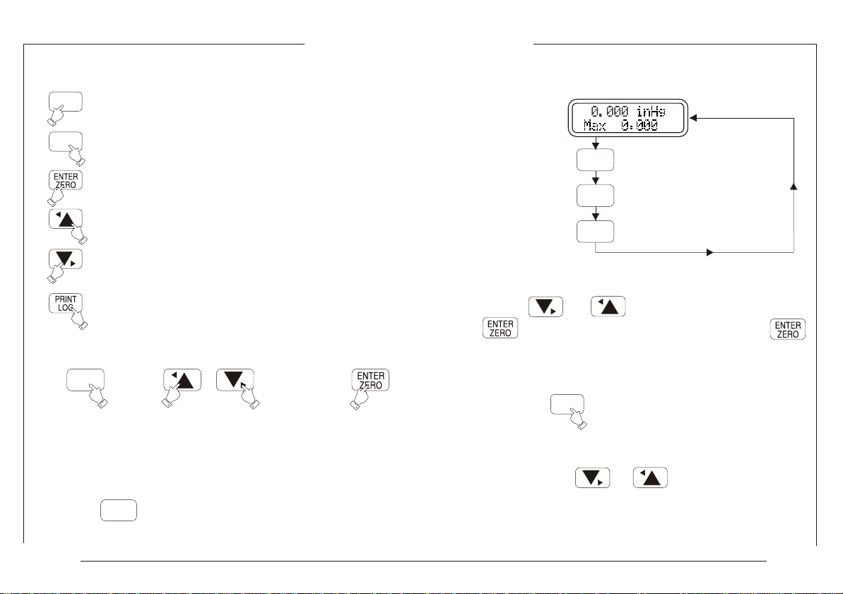
Data Entry
Press or to position cursor and press
to select required alphanumeric. Press
key to release cursor.
For next data entry, repeat the above procedures
then press once all data is entered
Note: To quickly scroll through alphanumeric lists
hold down the or key.
MENU
Issue 3 Page iii
MANUFACTURER'S SPECIFICATIONS
Model
PC6-0002A-I-1-P-AV
Pressure Range (FS)
0 to 2 bar (+60 inHg)
absolute
0 to 600 knots*
Overload
Pressure (FS)
10%
Pressure Units mbar, inHg,knots, kPa,MPa,psi,kg/cm2,atm,
inH 0, mH 0, mmH 0, bar, mmHg, unit, unit2
22 2
Overload Warning Flashing display and audible tone at 110%
of FS
Resolution 6 digits
Temperature Display Temperature of pressure sensor module
Operating Temperature -20 to 70°C
Calibration Temperature 20°C ± 2°C
Storage Temperature -40°C to 70°C
Temperature Effects 0.001% of reading/°C between 10-40°C
RS232 Parameters baud rate 1200, 2400, 4800, 9600, stop bits
1 or 2, status ON/OFF
Zero Reset Manual keyboard operation
Data Capacity 436 records into a maximum of 20 files, 32k
memory additional 585 records, ( 32k
memory option available )
Display Backlit LCD, 16 character x 2 line alpha
numeric
Humidity 5 to 95% Relative Humidity non condensing
Resolution Select Increase or decrease by a factor of 10
Power Supply 6V Ni-MH rechargeable battery pack (see
warning page ii)/ mains operation via
charger (supplied).
Battery Life Fully charged - 10 hours
Recharge Time 14-16 hours for full charge
Accuracy (FS)
Better than
0.025%
Resolution (FS)
Better than
0.01%
Low Battery Continuous check, audio and visual
warning
Dimensions 92 x 110 x 59mm
Weight 850 grams (Calibrator head only)
Microprocessor H8/2138
Recommended Recalibration Period 1 Year
Electrical Connections
Battery 2 pole miniature round connector
RS232 8 pole miniature round connector
Pressure Media Non-corrosive gases
(for other media, contact SI)
Pressure Connections 3/8“BSP Quick-fit.
8mm O/D hose connector
Pressure Switch Input Standard 2mm sockets
Software (optional) The ‘SiCal PRO’ software will present
downloaded data in various graphical
forms such as gauges or a scrolling bar
& remotely control the PC6-PRO via
the RS232 cable linked to a PC. The
downloaded data can be stored in a
variety of file types compatible with
most analysis database and word
processing programs.
Cal. procedures can be uploaded to
the PC6-PRO.
System requirements: 486 with maths coprocessor.
Windows 95 or higher is required.
®
knots
Pressure to airspeed conversion for the range 0 to 600 knots using
‘British Standard 2G 199 :1984’
Issue 3 Page iv

DESCRIPTION

1.0 Introduction
The unit is a microprocessor controlled, precision instrument powered by an internal 6V rechargeable battery
pack. It is portable and capable of accurate pressure measurement. This section describes the equipment
from an external viewpoint, allowing the user to become familiar with the various controls and connections
provided.
1.1 General
The PC6 is housed in a three part anodised aluminium case with a liquid crystal display unit at the front and a
six button membrane keyboard. The main body contains the circuitry, connections, internal transducer and
battery pack.
1.2 Keypad
The Keypad is a non-tactile membrane keyboard with six buttons. The keyboard layout is shown below.
Note: An audible bleep accompanies
every key operation.
MENU
PRINT
LOG
ON/OFF
ENTER
ZERO
Issue 3 Page 1
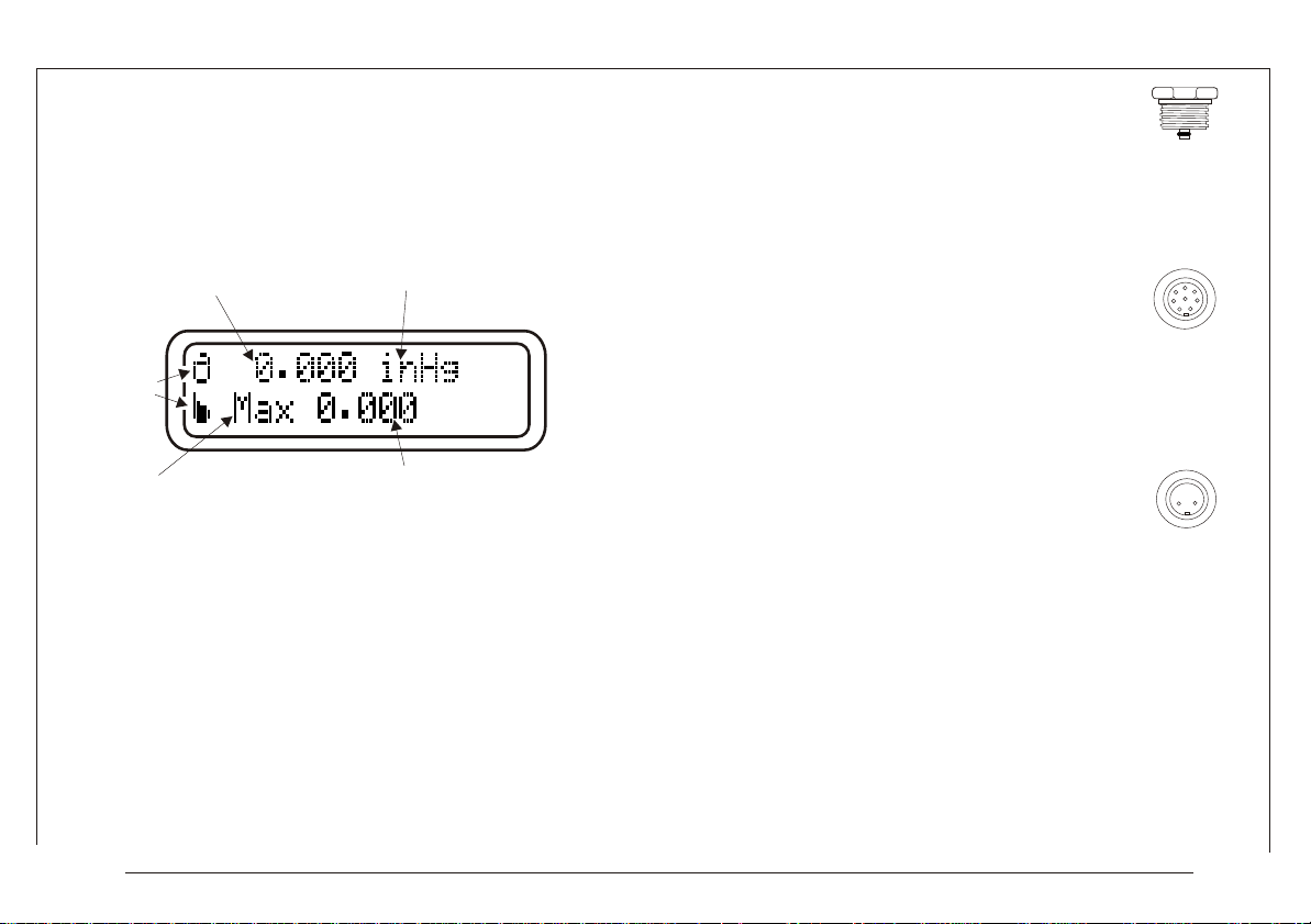
1.3 Liquid Crystal Display (LCD)
The LCD is a 16 character x 2 line alphanumeric LED
backlit display which is capable of displaying special
characters.
Pressure reading Unit of measurement
Special
Symbols
1.4.1 A 3/8“BSP ‘Quick-fit’ coupling to
accommodate the hand pump.
8mm O/D hose fitting on pump to connect
to item under test.
1.4.2 An 8 way circular miniature
connector is used for communication with
RS232 standard communication
protocols/equipment. The user software
‘SiCalPro’ (optional) can be used to
remotely monitor or download data from
the PC6 via this connector.
(Optional RS232 cable - Part No. 01-0625)
COUPLING
RS232
CHARGER
CHARGER
Function Function Value
1.4.3 The 2 way circular miniature
connector is used for the battery charger
(provided).
1.4 Connection Panel (See Page 3, Fig 2)
The connection panel is located at the top of the case and
provides input / output connections as detailed in Fig.2
Issue 3 Page 2

ARRANGEMENT OF PC6-AV
Front View: LCD & keypad
Keypad
See Page 1
MENU
Fig 1
Display.
PRINT
LOG
PC6-A V
ENTER
ZERO
ON/OFF
‘Quick-Fit’ Coupling.
Top View: connection panel
Fig 2
BATTERY
Battery Charger Input Socket
CHARGER
++
--
See Page 7
RS232 Communication
Socket See Page 7
CHARGER RS232
GND
GND Common Ground Socket
SWITCH Pressure Switch Input.
SWITCH
Issue 3 Page 3

PRESSURE DISPLAY - Allows the user to operate the PC6 for pressure measurements. (Display Functions)
FUNCTIONS (MENU 1)
Menu 1
Issue 3 Page 4
UNITS Selection of pressure unit.
ALT (ft) Altitude in feet
ALT (m) Altitude in metres
QFF Airfield barometric pressure at sea level.
MAX Displays the maximum pressure measured since the last reset.
MIN Displays the minimum pressure measured since the last reset.
% Displays the pressure as a percentage between user pre-set high and low alarm values.
TARE Displays the pressure at the time of tare.
Switch Indicates the status of the pressure switch (OPEN/CLOSED)
Leak Allows the PC6 to measure pressure changes over time.
Temp °C Allows the user to monitor the temperature around the selected pressure transducer in pressure display mode.
Date & Time Allows the user to monitor the date & time of the on board real time clock in pressure display mode.
File Allows the user to view or manipulate a file previously stored in the filing system.
Exit Returns to Pressure Display mode. (SHORTCUT: To abort any menu level, simply press the MENU key).
mbar millibar
inHg Inches of Mercury (at 4°C)
knots knots (for absolute units see item 2.12, page 10)
kPa kiloPascals
Mpa Mega paskals
psi pound force per square inch
kg/cm2 Kilogrammes force per square centimeter
atm atmospheres
inH O inches of Water (at 4°C)
2
mH O meters of water (at 4°C)
2
mmH O millimeters of water (at 4°C)
2
bar bar
mmHg mm of Mercury (at 0°C)
Unit1 First user defined unit
Unit2 second user defined unit
Exit Returns to menu 1
Start Starts the leak test.
Set-Time Sets the leak test time.
Exit Reverts back to pressure display mode.
View Allows the user to see stored file.
Export Outputs a stored file.
Import Imports a file from Sicalpro
Delete Deletes a stored file.
Exit Reverts back to pressure display mode.
Please see 3.6 page 23
}
Refer to item 2.12, page 10
}
when using ‘knots’.

FUNCTIONS (MENU 2)
SETTING MENU - To set user specific functions. (Set Functions)
Menu 2
ALT Configure altitude settings
QFF Configure QFF mode
High Allows the user to set a High Pressure Alarm Limit.
Low Allows the user to set a Low Pressure Alarm Limit.
Display Light Switches ON or OFF the LED back light.
Resolution Selects high, normal or low resolution.
Event Sets up the event status for RS232 output and for logging functions.
Log Allows the user to setup, amend and view files for logging.
RS2332 Settings for RS232 communications.
Date/Time Sets up Date & Time parameters
Language Allows user to change language
Issue 3 Page 5
Datum User defined setting
View Allows user to view current datum
Set Allows user to define current datum
ISA Displays ‘International Standard Pressure’.
Exit Reverts back to pressure display mode.
Height Sets Local height
Temp Sets local temperature
Exit Reverts back to pressure display mode.
(by using the increase/decrease facility above which an alarm sounds.)
(by using the increase/decrease facility below which an alarm sounds.)
Key Sets key driven output.
Timed Sets timed output defined by the user.
Exit Reverts back to pressure display mode.
Log To select a log file and start logging.
View To look at a file.
Delete Deletes a file.
Status To enable or disable logging.
Export To export logged files.
Import To import files from a PC. (see ‘SiCalpro’ software instructions for exporting files to the PC6)
Status To enable RS232 communication.
Baud-rate To select the baud rate.
Stop-bits To select the number of stop bits.
Exit Reverts back to pressure display mode.
Set Sets the date & time.
View To look at date & time.
Exit Reverts back to pressure display mode

Zero Will reset pressure reading to Zero. ( This will remove Zero offset permanently / NOT available for
Port Selects current pressure modules (P1,P2,DPM)
Power_Off Allows the user to set Power_Off time or to switch the function on or off.
Key Switches the auto-power function off.
Timed Allows the user to set the auto-power off time in minutes.
Exit Reverts back to Pressure Display.
Exit Reverts back to pressure display mode.
absolute units ).
FUNCTIONS (MENU 3)
CAL MENU
Menu 3
SPAN Allows user to set span.
CONTINUE Starts span calibration procedure.
EXIT Returns to Cal Menu.
HISTORY Allows user to see overload and zero-span history.
OVERLOAD Displays period of time over which overload occurred.
ZERO-SPAN Displays date last calibrated, last span set, range and overload value.
PC6 S/No Displays the unit’s
PM S/No Displays the serial number of the currently selected pressure module.
EXIT Returns to Cal Menu.
Language Allows user to download different languages.
UNITS
View Displays the two current user-defined units.
Alter Allows user to modify the conversion factor and/or text for the two user-defined units.
Exit Returns to Cal Menu
EXIT Returns to Pressure Display.
Issue 3 Page 6
serial number.

OPERATING
INSTRUCTIONS
1.5 Switch Test Activate ‘Switch’ function in menu 1. The
switching pressure of a pressure switch can now be
monitored by connecting the contacts of the pressure
switch between the INPUT 'GND' and 'SWITCH' sockets on the
connection panel and pressurizing the pressure switch.
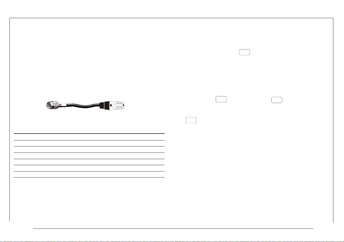
1.6 RS232
If the RS232 facility is to be used then connections to the 8way socket must be made to the specifications given in the
table below. Alternatively an RS232 communication cable
can be purchased from SI suitable for most RS232
applications as shown below.
To RS232 Standard 9-way
socket on PC6 'D'type female
Cable Part No: 01-0625
connector
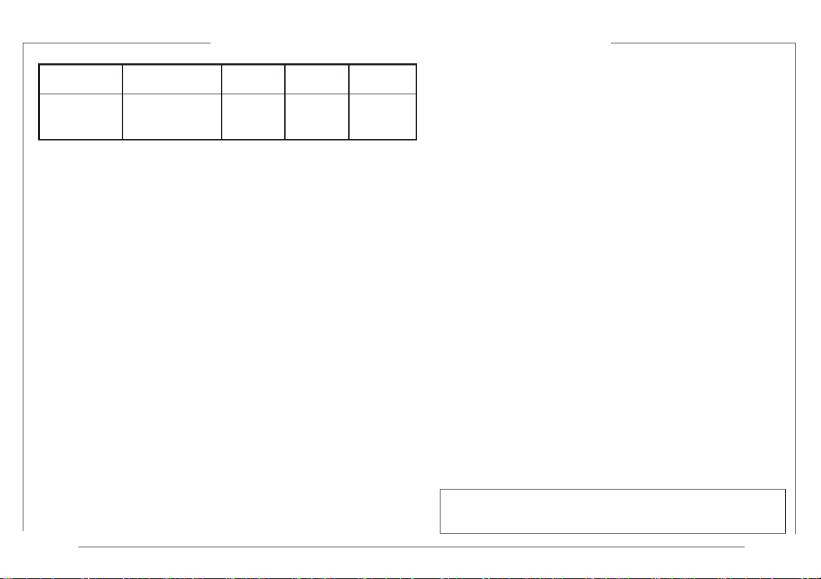
RS232 Connections Table
PIN No.
Note: 1. Pin 6 and pin 8 should not be used.
INPUT/OUTPUT
1
2
3
4
5
6
7
8
Output
Output
Input
Output
Input
Output
Common
Input
Data Terminal Ready (DTR)
SIGNAL
Transmit Data (TxD)
Receive Data (RxD)
Request To Send (RTS)
Clear To Send (CTS)
Do not use
Ground
Do not use
STATE
Held High
Active High
be obtained as ‘single shot' or ‘timed' as follows:
Single Shot - This output is always available in Display mode
when RS232 status & Log status are OFF. The output is
obtained each time the key is pressed (provided any
PRINT
LOG
previous output is complete).
Warning: The PC6-PRO must be switched off prior to
connecting or disconnecting the RS232 cable.
Timed - This output is available in Display mode when RS232
status is ON & Log status is OFF. The output cycle is initiated
by pressing the key. Pressing the key cancels the
PRINT
LOG
MENU
output. Once initiated, the output is repeated at the
selected time interval (see ‘Event' function, page 26 ) until
MENU
the key is pressed.
1.6.1 Charger The internal battery pack may be recharged
(when indicated by the battery low message) by plugging the
charger (supplied) into the 'CHARGER' socket of the PC6.
CAUTION: When recharging internal batteries, only the
charging unit supplied with the PC6 should be used.
RS232 Output
Connect the PC6 to a printer or computer using a suitable
cable (not supplied) as detailed above and set the
parameters as detailed in Para. 2.9 & 3.1. The output can now
Issue 3 Page 7

1.7 Messages & Parameters
The PC6 registers pressure input at switch on after the initial
start-up message. The pressure reading is displayed in the top
left hand corner of the LCD (Fig.3 Page 2). Pressure values are
monitored, alarm values are compared, alarm warnings and
other information messages displayed until the PC6 is switched
off.
Memory Errors:
Any read / write errors to memory detected at switch on will be reported
as: Memory Error ‘Error No.’
Error Numbers:-
0 - Onboard eeprom; 8 - RTC; 9 - 2nd Onboard
eeprom.
Errors with Pressure Modules will be indicated by the message: "No P1
(or P2 or DPM) Module" preceeded by "PM EEPROM ERROR" at power
on.
1.7.1 When switched on, the PC6 registers the same state as
when last switched off. The display mode (Operating/Set), units
of measurement, function and parameter settings, alarm limits
and RS232 output control, logged parameters are all retained
at switch off, with the exception of the following conditions :
1.7.2 A battery low state occurring prior to the switch off.
When switched on, the PC6 registers the latest retained set of
parameters.
1.7.3 Any TARE value set during use is not retained and
therefore should be set, if required, each time the PC6 is
switched on.
1.7.4 Maximum and Minimum values are not retained.
Current values reflect pressure monitored from the start of the
pressure input.
1.7.5 If the PC6 is switched off during a LEAK test then the test
will be void. When switched on again the PC6 will start up in
LEAK test mode.
1.7.6 Switch off When the key is pressed the 'switch
ON/OFF
off' message is displayed for five seconds accompanied by
an audible bleep. Normal operation may be resumed by
pressing any key during switch off.
1.7.7 Auto Switch off The PC6-PRO will automatically turn itself of
after a set period (See Page 20 for instructions)
1.7.8 Pressure Overload (Bleep rate 4 Hz) ‘OVERLOAD'
occurs when input pressure exceeds overload pressure level.
1.7.9 Low Battery Detect (Bleep rate 1 Hz). ‘Low Battery'
occurs when internal battery pack drops below 5.5V. Message
flashes for 4 seconds, after a further 30 seconds, low battery
detection is re-enabled.
1.7.10 Pressure Switch State Change (Bleep rate 2 Hz)
Occurs in pressure mode with the pressure switch state display being
selected. When the connected pressure switch changes state, the
pressure value (upper line) is frozen and the pressure switch state (lower
line) display is flashed at 1 Hz unless a log file is open. Normal display
update resumes when the key is pressed.
ENTER
ZERO
Issue 3 Page 8

1.7.11 Printer Busy (Bleep rate 1 Hz) the various pressure alarm conditions as given below:
If the receiving device is not ready for input (e.g. device not
connected or handshake LOW), 10 seconds after starting an
output cycle (single shot or timed output) the message 'Printer
Busy' is flashed on the display, together with an audible
warning. If the device does not accept input within the next 5
seconds then the output cycle is canceled and output is
stopped until the key is pressed again.
PRINT
LOG
1.7.16 Display Symbols
* overload pressure level exceeded
(pressure warnings, 1.7.8 & 1.7.12)
> pressure exceeds user set high limit
< pressure below user set low limit
“ ” a space if no alarms apply.
1.7.12 Outside User Set Alarm Values (Bleep rate 2 Hz)
Occurs when measured pressure is lower than the user set Low
Log Log Status ON RS232 Output
File open Status ON
DPM
Status ON
alarm value or greater than the user set High alarm value and
the ’outside limits’ message is flashed. Indication ceases when
pressure is equal to either alarm value or between the values.
1.7.13 Display Hold (Bleep rate 2 Hz)
Occurs in pressure mode. If the key is pressed once (less
ENTER
ZERO
than 1 second) the pressure value (upper line) is frozen and the
lower line is flashed with the ‘Display Hold’ message at 1 Hz.
Normal display update resumes when any top row key is
Top line symbols
Timed Keyed log/output
Log/output
Pressure
Port 1
selected
Note: If two (or more) conditions occur which require a
message display, the highest priority condition in the above list
will be displayed. The sequence of messages given above set
the priority except 'Switch Off' which comes last.
pressed.
1.7.17 Alt (height) warning
1.7.14 RS232 Output Format The output format is as follows:
LF
An “Out of Range” message is displayed if the height is
exceeds 105,000 ft or is less than -3000 ft (32004m, -914.4m)
Time & date 23:13:30 220997 +LF
display top line (16 characters ) + LF
display lower line (16 characters ) + LF
alarm flag (1 character ) + LF
1.7.18 Knots (limits)
An “Outside limits” message is displayed if the reading exceeds
600 knots.
Null terminator ( 0 )
1.7.15 Alarm Flags A single character is output to indicate
Issue 3 Page 9
 Loading...