

Page 1
GE Industrial
Sensing
Druck DPI 104
Digital pressure indicator
User manual - K394
Page 2
A1.1 A1.2
1
A2
2
3
6
5
4
A1.3
B1
B2
7
8
9
10
A2
K394 Issue 1
13 11
14
15
12
16
Page 3
Table of Contents
Introduction ......................................................................... 1
Safety .................................................................................... 1
Marks and symbols on the DPI 104 ....................................... 1
To Start ................................................................................. 2
Location of items ........................................................................... 2
Items on the display .................................................................... 2
Prepare the instrument ............................................................... 2
Power on or off ................................................................................ 2
Menu operation ............................................................................... 3
Installation ........................................................................... 4
Battery.................................................................................................. 4
Position ................................................................................................ 4
Pressure connections ................................................................... 4
Electrical connections .................................................................. 4
Operation ............................................................................. 5
Menu: Set units ................................................................................ 5
Menu: Set tare .................................................................................. 5
Menu: Monitor maximum/minimum ..................................... 5
Menu: Monitor a pressure switch ............................................ 6
Menu: Calibration ........................................................................... 6
Menu: Set low/high alarm .......................................................... 6
Menu: Supply voltage output (Vout) ...................................... 6
Menu: Set Vout scale factor ...................................................... 7
Menu: Set automatic power OFF ............................................. 7
Menu: Set lock code ....................................................................... 7
Menu: Set scan rate ....................................................................... 7
Menu: Monitor external IDOS .................................................... 7
Menu: Set FSO low/high registers ........................................... 8
Set up a DPI 104 network ........................................................... 8
Error indications .............................................................................. 8
Maintenance ........................................................................ 9
Replace the batteries .................................................................... 9
Restore the original configuration .......................................... 9
Calibration ............................................................................ 9
Equipment and conditions ......................................................... 9
Procedures ......................................................................................... 9
Specification data ............................................................. 11
General ............................................................................................. 11
Pressure measurement ............................................................ 11
Electrical .......................................................................................... 11
Customer service ............................................... Back cover
© 2005 General Electric Company. All rights reserved.
Trademarks
All product names are trademarks of their respective companies.
Introduction
The Druck DPI 104 is a digital pressure indicator that
measures the pressure of liquid, gas or vapour and shows
the pressure value on a liquid crystal display (LCD). It also
has the Intellige nt Digital Output Sensor (IDOS) technology
to use data from a Universal Pressure Module (UPM).
The DPI 104 includes these functions:
Function
* Measure pressure - Accuracy: 0.05% full scale (FS)
Large 5-digit main displa y with 11 pressure units
Adjustable Full Scale Output (FSO)
20 segment analogue dial in increments of 5% FSO
(large division marks = 10% increments).
2.5 digit percentage indicator (0 -100% FSO)
8-pin connector port: For RS232, **IDOS UPM, external power
supply
Alarm output for high/low pres sure conditions
Switch input to monitor an external pressure switch
Analogue voltage output (Vout): 0 - 5 Vdc
Other functions: Maximum/minimum, tare, Vout scale factor,
automatic power off
* Refer to “Specification data”.
** Optional item
Safety
Before you use the DPI 104, make sure that you read and
understand all the related data. This includes: all local
safety procedures, and this publication.
• Some liquid and gas mixtures are dangerous. This
includes mixtures that occur because of
contamination. Make sure that the DPI 104 is safe to
use with the necessary media.
• It is dangerous to ignore the specified limits for the
DPI 104 or to use the DPI 104 when it is not in its
normal condition. Use the applicable protection and
obey all safety precautions.
• To prevent a dangerous release of pressure, isolate
and bleed the system before you disconnect a
pressure connection.
• Do not use the DPI 104 in locations with explosive
gas, vapour or dust. There is a risk of an explosion.
Before you start an operation or procedure, make sure
that you have the necessary skills (if necessary, with
qualifications from an approved training establishment).
Follow good engineering practice at all times.
Safety - Marks and symbols on the DPI 104
Complies wi th European Union di rectives
WARNING
K394 Issue 1
[EN] English - 1
Page 4
To Start
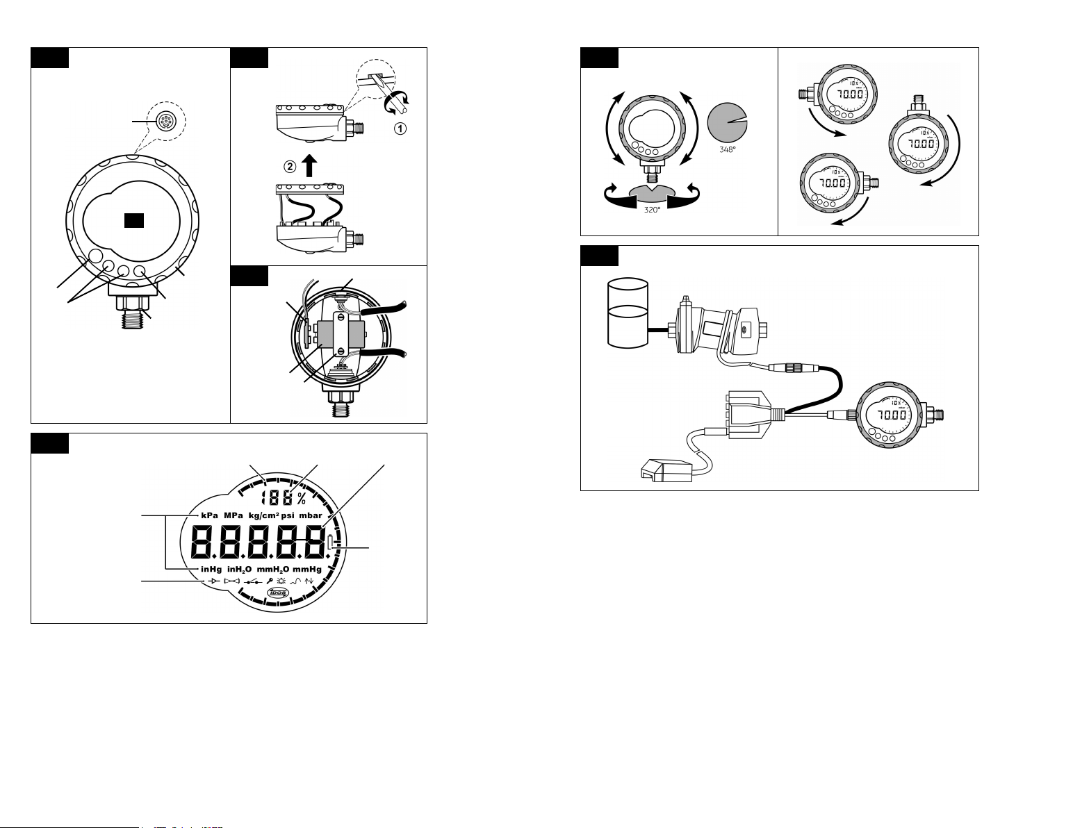
To start - Location of items
Item Description
1. 8-pin connector for external power supplies,
2.
3. In menu mode:
4. Pressure sensor and connector with 320° of turn:
5.
6. Display bezel with 348° of turn.
7. O-ring.
8. Battery connector
9. Battery: 9 V Alkaline (supplied but not installed). Refer
10. Battery clamp with two screws.
RS232/UPM connections an d signal input/output.
Power on button
•
Menu mode: Press for 2 seconds to show the first
•
menu option. To move down the menu structure,
press again and again, or press and hold.
Reject or stop the change to a value.
•
In Maximum/minimum mode. Press to show the
•
maximum and minimum values since the last reset.
- On/OFF selection
- Increase/decrease a value
- Move the decimal left/right
gauge (g), absolute (a) or Sealed gauge (sg). Refer to
“Specification data”.
In menu mode:
•
- Accepts a menu selection
- Shows the next menu level
- Accepts a value
In Tare mode: Tare the pressure value on the display.
•
In Maximum /minimum mode. Reset the
•
maximum/minimum values.
to “Installation”.
To start - Items on the display
Item Description
11. 5-digit main display.
12. 2.5-digit percentage indicator (0-100% FSO).
%FSO = [ Applied Pressure/ (FSOHigh —FSOL ow)] * 100
13. 20 segment analogue dial in increments of 5% FSO
(large division marks = 10% increments).
%FSO = [ Applied Pressure/ (FSOHigh —FSOL ow)] * 100
14.
The units of measurem ent: kPa, MPa, kg/cm
mbar, bar, mmHg, mmH
A1
= maximum = minimum
A2
2
O, mH2O, inH2O, inHg
2
, psi,
Continued
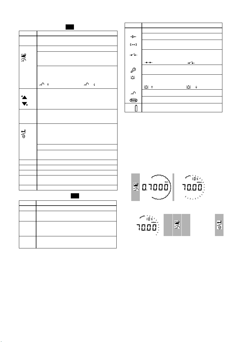
Item Desc ription
15. Mode indication.
Voltage output (V out) mode - On.
RS232 connectio n. The data transmit/receive function
is active.
Switch mode - On. To monitor an external pressure
switch.
= switch closed = switch open
Menu Lock mode - On. To restrict access to the menu
function s.
Alarm mode - On. The symbol flashes when the
measured value satisfies one of the alarm conditions.
= High alarm = Low alarm
Maximum/minimum mode - On.
IDOS UPM mode - On. To monitor pressure from a UPM
16. Low ba ttery power indication: Ba ttery life ≤ 15%.
To start - Prepare the instrument
Before you use the instrument for the first time:
• Make sure that there is no damage to the instrument,
and that there are no missing items.
• Install the battery (refer to “Installation”). Then
re-attach the display bezel [A1: item 6].
To start - Power on or off
Press the buttons in the sequence shown below.
• Power on sequence:
1
First displ ay =
FS limit
Then:
Normal output
• Power off sequence:
Normal output 1 Menu: 2
OFF
(For 2 sec onds)
When the power is of f, the last set of c onfiguration options
stays in memory.
Note: The DPI 104 uses a small quantity of power while it is
OFF. If you put it into storage for a long period, disconnect
the battery (refer to “Installation”).
2 - [EN] English
K394 Issue 1
Page 5
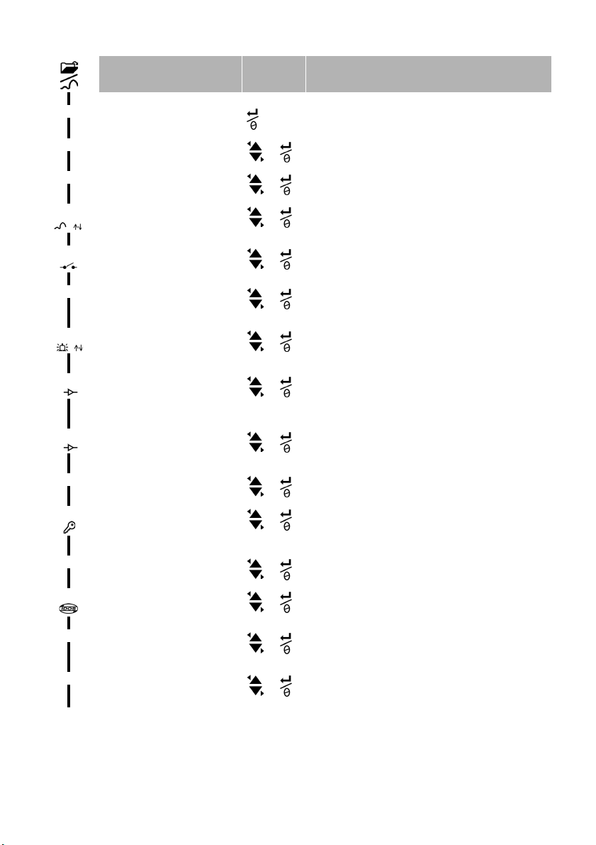
To start - Menu operation
Menu Description Steps Result/Subsequent steps
1 2
OFF = Power supply: OFF only
unitS = Set units: (A2: item 14). Pressure value changes to the applicable units:
t OFF = Set tare: Set to On or OFF. On ➤ tA 00.000 : Set a tare valu e (Refer to Table 4)
= Monitor maximum/minimum:
OFF
OFF
C _ _ _ _ = Calibration: To continue, set the
A OFF =Set low/high alarm: Set to On or OFF. On ➤ 000.0 ↓ ➤ 100.0 ↑
S 1.00 = Set Vout scale factor: A V out
Au On = Set automatic power OFF:
L OFF = Set lock code: A menu protection
Set to On or OFF
= Monitor a pressure switch:
Set to On or OFF.
correct calibration access code =
Serial number: Last four digits.
OFF = Supply volta ge output (Vout):
Set to OFF, P-V, or US.
adjustment.
Set to On or OFF.
facility. Set to On or OFF.
- Power goes off
psi, mbar, bar ...
Monitor function is set on or off
Monitor function is set on or off
C0 (Correct the zero offset value) ➤
C2 (Do a two-point pressure calibration) ➤
V2 (Do a two-point voltage calibration). Refer to “Calibration”.
Set a value for the low and/or high alarm (0 to 105% FSO).
P-V: Vout is proportional to the pressure value on the display. Make
sure the Vout scale factor is correct.
US ➤ 000.0: Set a V out value (0 to 100%) to control an external
pressure regulator. Make sure the Vout scale factor is correct.
If applicable, set a new V out scale factor (0.01 to 9.99).
Factory value = 1.00
On ➤ Au 15 : Set the period for automatic power OFF (1 to 99
minutes). Factory value = 15 minutes.
On ➤ L 000 : Set a new lock code (If necessary).
Factory code = 000.
Sc 02 =
Normal
display
Set scan rate: A rate to update the
maximum/minimum values
OFF = Monitor external IDOS: Set to O n or
OFF.
FS ↓ =Set FSO low register: To set a
different range for these functions:
analogue display, %, alarm.
FS ↑ =Set FSO high register: To set a
different range for these functions:
analogue display, %, alarm.
K394 Issue 1
Set an ap plicable rate (02 to 10 Hz).
Factory value = 02 Hz.
Monitor function is set on or off
Set a value for the low end of the range (Refer to Table 5).
Factory value = Factory calibration value.
Set a value for the high end of the range (Refer to Table 5).
Factory value = Factory calibration value.
[EN] English - 3
Page 6

Installation
This section shows how to install and connect the DPI 104.
Before you start:
• Read and understand the “Safety” section.
• Do not use a damaged DPI 104.
Installation - Battery ...
Use the procedures in Table 1 to install or replace the
battery.
Table 1: Installation procedures - Battery
Step Procedure
1 If applicable, set the power to off and isolate the
2 Remove the display bezel (Figure A1.2).
3 Make sure that the o-ring [A1 : item 7] and the related
4 Remove the battery clamp [A1: item 10].
5 If applicable, disconnect the battery connector
6 Attach the battery connector [A1: item 8] to the new
7 Install the new battery (Figure A1.3) and re-attach
8 Push the display bezel [A1: item 6] back into po sition
* Use an applicable recycling facility.
Installation - Position
Make sure that you attach the DPI 104 in a safe
configuration that prevents unwanted stress (for example
vibration, physical impact, shock, mechanical and thermal
stresses).
To get the best installation position, you can turn the
pressure connector (A1: item 4) and the display bezel
(A1: item 6) to give the best view of the display (Figure B1).
End stops set the limits in each axis.
CAUTION: To prevent damage when you are setting the
best view of the display, do not use force to turn the
pressure connector or the bezel farther than the end
stops.
Installation - Pressure connections
CAUTION: To prevent damage, d o not use the body of the
DPI 104 to tighten the pressure connection. Use the flat
faces on the pressure connector.
Use an applicable method to seal the pressure
connections, and then tighten to the applicable torque
(Figure 1 and Table 2).
A1.2 A1.3
external power supply.
surfaces are serviceable. Us e only original parts
supplied by the manufacturer.
[A1: item 8] and *discard the used battery.
battery.
the battery clamp [A1: item 10].
until it is fully engaged.
1
2
1
3
1
a) 1/4 NPT:
Pressure
<
1000 bar (15000 psi)
b) G1/4:
<
1000 bar (15000 psi)
Pressure
c) 9/16 x 18 UNF cone:
≥
1000 bar (15000 psi)
Pressure
Figure 1: Connection methods
Table 2: Key to figure 1
Item Des cription
1. Applicable DPI 104 pressure connector. Maximum
2. (1/4 N PT only) Thread wi th an applicable sea lant
3. (G1/4 only) Applicable bonded seal
torque:
1/4 NPT: 68 Nm (50 lbf.ft)
G1/4: 20 Nm (15 lb f.ft)
9/16 x 18 UNF cone: 34 Nm (25 lbf.ft)
Installation - Electrical connections
The DPI 104 includes an 8-pin electrical connector
(A1: item 1). Table 3 shows the pin connections.
Table 3: Connections for the 8-Pin connector
Connector Pin Input/
Output
1. Input 12- 24V dc power supply
2. Input Signal ground
3. Output RS232 transmit
4. Input RS232 receive
5. Output Voltage output
6. Output Alarm outpu t
7. Input Pressure switch input
8. Output No connection
Descriptio n
These optional accessories use the connector:
• RS232 PC connection
• external IDOS UPM connection + power supply adaptor
Note: Use only original parts supplied by the manufacturer.
You can also use the RS232 interface to make a serial
network of units (maximum: 99). Refer to “Operation - Set
up a DPI 104 network”.
Electrical connections - External power
We recommend you use an external power supply for
these functions and operations:
• Functions: Maximum/minimum, Switch,
Low/high alarm, Vout, IDOS
• Operations that use the DPI 104 for long periods
4 - [EN] English
K394 Issue 1
Page 7

Operation
This section shows how to use the DPI 104. Before you
start:
• Read and understand the “Safety” section.
• Make sure that the installation is complete (Ref er to the
“Installation” section).
• Do not use a damaged DPI 104.
Operation - Menu: Set units
There are 11 different units to measure pressure. Refer to
the “Specification data” section.
Units - Set up
Refer to “To start - Menu operation”.
Operation - Menu: Set tare
Use the tare function to adjust the pressure value on the
display. For example: To make an adjustment for
atmospheric pressure. Refer to Table 4.
Table 4: Permitted tare values
Range Permitted tare values
g: 0.7 bar (10 psi) -0.7 bar (-10 psi) to 105% FS
a, sg, g: ≥ 2 bar (30 psi) -1 bar (-15 psi) to 105% FS
If you set a value that is not in the permitted range, the
value is rejected and the number entry prompt reverts to
the last accepted value.
Tare - Set up and use
Menu: Set this function to On (Refer to “To start - Menu
operation”).
When this function is On, there are two optio ns to set a tare
value (tA):
• Menu option: Set the menu “t On”, then set a tA value:
tA display 12 tA display
To make sure that there is an indication of the correct
pressure while tare is On, the analogue dial and %
indication show values calculated from the calibrated
range without the tare adjustment.
Tare - With Lock
If the menu lock is On with a lock code set < 500, the zero
option is rejected - Error code (E0002).
Tare - With Alarm and/or Vout
If you set a tare value (tA) while the alarm and/or V out
functions are On, the display counts down from:
tArE9 to tArE0.
If the tA value is set, the alarm and V out functions start to
use values calculated from the calibrated range.
To cancel the specified tA value, press this button.
To continue with the specified tA value, press this
button OR let the count complete.
Tare - With FSO values
To make sure that there is an indication of the correct
pressure while tare is On, the FSO Low and/or FSO High
values are not used.
Operation - Menu: Monitor maximum/minimum
When this function is On, it updates its data at five times
the specified scan rate (02 to 10 Hz). Refer to “To start Menu operation”.
To save battery power, we recommend that you use an
external power supply with this function.
Maximum/minimum - Set up and use
Menu: Set this function to On (Refer to “To start - Menu
operation”).
When this function is On, use steps 1 + 2 to show the
maximum/minimum since the last reset.
1 maximum 2 minimum 3
0 to 9, or - 0 to 9
Repeat steps 1 + 2 for each digit and for the decimal
point.
• Zero option: Step 1 lets you set a value for tA. Press and
hold.
Normal
output
tA = 0 tA = 70 mbar
1
donE
Normal
output
When tA is not zero, the last segment on the analogue dial
flashes.
K394 Issue 1
donE
Reset
Step 3 lets you reset the values for maximum/ minimum.
Press and hold.
[EN] English - 5
Page 8

Operation - Menu: Monitor a pressure switch
Use this function to measure the performance of a
pressure switch (mechanical operation and hysteresis).
To save battery power, we recommend that you use an
external power supply with this function.
Pressure switch input - Set up and use
1. Connect the instrument (Figure 2/Table 3).
2. Menu: Set this function to On (Refer to “To start - Menu
operation”).
Pin 1 (+), 2 (GND)
12- 24V dc
Pin 7 (Switch)
Pin 2 (GND)
Figure 2: Example configuration - Switch input
Figure 2 shows the display when the switch condition
changes (open or closed). The analogue dial and the %
indication continue to monitor the normal pressure.
The switch symbol and the value on the main display flash
to give the switch condition and the switch pressure.
To reset the monitor function, press this button.
Operation - Menu: Calibration
Refer to the “Calibration” section.
Operation - Menu: Set low/high alarm
Use the alarm function to show when the pressure is not in
the specified limits for the system.
Set applicable values in the range 0 to 105% FSO:
%FSO = [ Applied Pressure / (FSO High — FSO Low) ] * 100
Note: If you set a tare value, the alarm function uses the
calibrated range (Refer to “Operation - Menu: Set tare”).
The alarm indication is available on the display and as a
signal output (Table 3).
While there is an alarm condition, the applicable alarm
symbol (high or low) flashes on the display (A1: Item 15).
To save battery power, we recommend that you use an
external power supply with this function.
Low/high alarm - Set up and use
Menu: Set this function to On (Refer to “To start - Menu
operation”). Then use these steps to set the low and/or
high alarm.
Alarm
(% FSO)
Digit = 0 or 1 Digit = 0 to 9
12
Alarm
(% FSO)
34
5. To finish, repeat steps 3 + 4 for each digit.
If the value you enter is not correct, the value resets to the
nearest permitted value. That is:
• a value in the range 0 to 105% FSO
• a low alarm value < high alarm value
To accept or change the new value, repeat steps 1 to 5.
To cancel the new value, press this button.
Operation - Menu: Supply voltage output (Vout)
Use the Vout function to supply a voltage output (0 to 5V)
to an external system. There are two options:
P-V: Vout is proportional to the pressure value on the
display.
US: User mode. Set a value in the Vout register (0 to
100%) to control an external pressure regulator.
To save battery power, we recommend that you use an
external power supply with this function.
P-V mode voltage calculation
Example DPI 104: FSO = 20 bar (or 300 psi),
Vout scale factor = 1.00.
If you apply 10 bar (or 150 psi) to this DPI 104:
Vout = ( 10/20 * 5V ) / 1.0 OR ( 150/300 * 5V) / 1.0 = 2.5V
US mode voltage calculation
This calculation uses the values set up for the V out register
and the Vout scale factor.
If the pressure ranges for the DPI 104 and the regulator are
different, set a new V out scale factor (refer to “Operation Menu: Set Vout scale factor”).
Vout = ( Vout register / 100 ) * 5V
Vout scale factor
Example if the Vout register is set to 25%, and the V out
scale factor is set to 0.5:
Vout = ( 25/100 * 5V ) / 0.5 = 2.5 V
Voltage output (V out) - Set up and use
1. Connect the instrument (Figure 3).
2. Menu: Set this function to OFF, P-V, US (Refer to “To
start - Menu operation”).
6 - [EN] English
K394 Issue 1
Page 9

Pin 1 (+), 2 (GND)
12- 24V dc
Vout: 0 to 5V
Pin 5 (Vo)
Pin 2 (GND)
Figure 3: Example configuration: V out
Operation - Menu: Set V out scale factor
When the V out function is set to P-V or US mode, the Vout
scale factor becomes part of the V out calculation (refer to
“Operation - Menu: Supply voltage output (Vout)”).
If the pressure ranges for the DPI 104 and the external
pressure regulator are different, you must set an
applicable scale factor (0.01 to 9.99).
Example - To get a 25 bar (or a 375 psi) line pressure with:
• an External pressure regulator:
FSO = 100 bar (or 1500 psi)
• a DPI 104: FSO = 200 bar (or 3000 psi)
In this example:
Scale factor = 100/200 OR 1500/3000 = 0.5
Vout register (%)
(DPI 104)
= (25/200) * 100 OR (375/3000) * 100
= 12.5%
To get a 25 bar (or a 375 psi) line pres sure, the DPI 104 uses
these values to supply the Vout value shown below:
Vout = ( 12.5/100 * 5V ) / 0.5 = 1.25 V
Operation - Menu: Set automatic power OFF
Use this function to save battery power. The power goes
off a specified period after the last button or external
software operation. To get the maximum battery life, we
recommend you use this function.
Note: The DPI 104 uses a small quantity of power while it is
OFF. If you put it into storage for a long period, disconnect
the battery (refer to “Installation”).
Automatic power OFF - Set up and use
Menu: Set this function to On. Then set an applicable value
in the range 1 to 99 minutes. Refer to “To start - Menu
operation”.
Note: If continuous operation is important, set this function
to OFF and use an external power supply.
Operation - Menu: Set lock code
Use the lock function to prevent accidental changes to the
configuration. There are two options:
• Lock code < 500: This locks the menu and the tare
function. Factory code = 000
• Lock code > 499: This locks the menu but you can still
use the zero option to set a tare value.
Refer to “Operation - Menu: Set tare”.
Lock code - Set up and use
Menu: Set this function to On (Refer to “To start - Menu
operation”). Then use these steps to set a new code.
Lock 12 Lock
Digit = 0 or 9 Digit = 0 to 9
3. To finish the lock code, repeat steps 1 + 2 for each digit.
The next time you want to change the menu options, the
display shows: L - - Enter the applicable code. To reset the code to the factory
code, you must do a restore operation. Refer to
“Maintenance”.
Operation - Menu: Set scan rate
Use the scan rate function to set the rate used to update
the maximum/minimum values.
Note: When you increase the scan rate, you increase the
power consumption. The maximum/minimum function
updates its data at five times the specified scan rate.
The rate for the normal pressure display is always 2 Hz.
Scan rate - Set up and use
Menu: Set an applicable value in the range 2 to 10 Hz. Refer
to “To start - Menu operation”.
Operation - Menu: Monitor external IDOS
Use this function to read the pressure from an external
IDOS UPM. The calib ration function is not available but you
can use all the other DPI 104 pressure functions. Example:
Set tare, Monitor maximum/minimum.
This function does not supply power to the IDOS UPM. To
use it, you must have the optional external IDOS UPM
connection + power supply. This optional accessory uses
the RS232 connections in the 8-pin connector (Table 3).
Monitor external IDOS - Set up and use
1. Connect the instrument (Figure B2).
2. Menu: Set this function to On (Refer to “To start - Menu
operation”).
3. If necessary, set the applicable additional functions
specified in this manual.
K394 Issue 1
[EN] English - 7
Page 10

Operation - Menu: Set FSO low/high registers
Use the FSO low/high registers to set a different range for
these functions: analogue display, % indication, low/high
alarm.
Initially, these register values are set to the factory
calibration values. Example:
Calibrated range: 0.7 bar (10 psi) gauge.
Selected units: mbar
FSO low FS O high
12- 24V dc
PC: 9-way, D-type
connector
GND Tx
RxGND+ve
0 bar (0 psi) 700 mbar (10 psi)
Table 5 gives the permitted alternative values you can use.
Table 5: Permitted FSO values
Range Permitted FSO values
All ranges: a, sg 0 to 105% FS
g: 0.7 bar (10 psi) -0.7 bar (-10 psi) to 105% FS
g: ≥ 2 bar (30 psi) -1 bar (-15 psi) to 105% FS
All ranges FSO low < FSO high
FSO low/high registers - Set up and use
Menu: Set the menu option to the FSO low register (Refer to
“To start - Menu operation”). Then use these ste ps to set an
applicable value in the permitted range (Table 5):
FSO low 12 FSO low
0 to 9, or - 0 to 9
3. Repeat steps 1 + 2 for each digit and for the decimal
point.
If the value you enter is not correct, the value resets to the
nearest permitted value (Table 5).
To accept or change the new value, repeat steps 1 to 3.
To cancel the new value, press this button.
4. If necessary, repeat the procedure for the FSO high
register.
Operation - Set up a DPI 104 network
You can set up a network of up to 99 units in series (‘daisy
chain’). Figure 4 shows the electrical connections to do this
(Refer to Table 3).
DPI 104 (2)
DPI 104 (1)
Figure 4: Connections for a DPI 104 network
Operation - Error indications
Table 6: Error codes/indications
Code Description
E0001 Incorrect unlock code. U se the correct code.
E0002 The tare facility is not available because the menu
E0004 Start up error. Do a restore operation (Refer to
E0005 External IDOS UPM not found. Make sure that all the
E0006 Incorrect calibration access code. Use the correct
E0007 The power supply is too low to do a calibration. Use an
E0009 Unable to supply the specified Vout. Example:
OLoAd Applied pressure ≥ 110% FS. Reduce the pressure.
99999/
-9999
lock is On and the lock code < 500. Change the menu
configuration.
“Maintenance ”).
related equipment an d connections are serviceable.
code.
external power supp ly or replace the battery.
• Low battery. Use an external power supply or
replace the battery.
• Bad connection. Make sure that all the related
equipment and connections are serviceable.
There are not enou gh digits in the main display to give
the correct pressure value. Change the measurement
units.
8 - [EN] English
K394 Issue 1
Page 11

Maintenance
Clean the case with a moist, lint-free cloth and a weak
detergent. Do not use solvents or abrasive materials.
Make sure that there is no damage to the threads and
O-rings, and that they are free of grit and other
obstructions.
You must return the unit to the supplier for all repairs.
Maintenance – Replace the batteries
To replace the batteries, refer to “Installation”. All the
configuration options stay in memory.
Maintenance – Restore the original configuration
If it is necessary to restore the unit to the original factory
configuration, press and hold all four buttons until the
display goes off ( ≈ five seconds). The unit then restarts.
“To start - Menu ope ration” shows the factory settings. T he
lock code is reset to the factory code (000).
Calibration
Note: GE can provide a calibration service that is traceable
to international standards.
We recommend that you return the DPI 104 to the
manufacturer or an approved service agent for
calibration.
If you use an alternative calibration facility, make sure that
it uses these standards.
Calibration - Equipment and conditions
To do an accurate calibration, you must have:
• the calibration equipment specified in Table 7.
• a stable temperature environment: 20 ± 1°C (68 ± 2°F)
Table 7: Calibration equipment
Function Calibration equipment
Pressure An applicable pressure standard (primary or
Volts (V) Volts calibrator.
Calibration - Procedures
1. Connect the applicable calibration equipment (Table 7).
2. Menu: Set the menu option to C _ _ _ _ . Then set the
secondary) with a total uncertainty of 0.01% reading
or better.
Make the pressure conne ction to A1 - item 4. Refer to
“Installation”.
Accuracy: 0.025% reading or better.
Make the Vout connection to A1 - item 1. Refer to
“Installation”
calibration access code = last four digits of the serial
number (Refer to “To start - Menu operation”).
There are three calibration options (Table 8):
Table 8: Calibration options
Option Descrip tion
C0: Set the necessary offset value for the instrument to give
the correct pressure related to zero:
All ranges g or sg: Zero (bar/psi);
Ranges a: Ambient pressure*
C2: Do a two-point pressure calibration.
All ranges g or sg: P1 = Zero (bar/psi); P2* = FS
Ranges a: P1* = Ambient pressure; P2* = FS
V2: Do a two-point voltage calibration.
All ranges: P1** = 0.1000 V; P2** = 5.0000 V
* adjustable by 5% FS; ** adjustable by 50 mV
To move to the next option without a change to the
values, press this button.
To stop and make changes to a value, press this
button.
To return to the normal display, wait eight seconds.
Calibration - C0 (Zero offset)
The DPI 104 shows these displays:
1. The calibration point to be used for C0. This value is
only adjustable for an absolute type DPI 104 (Table 8).
C0 - Gauge = 0000.0
C0 - Absolute 2 C0 - Absolute 34
8 seconds 0 to 9
5. Repeat steps 3 + 4 for each digit and for the decimal
point. The value is ignored if it is not in the permitted
limits (Table 8).
This value is then used as the Set Point (SP) on the
subsequent displays.
6. This sequence of displays will follow:
C0
Example sequence: A bsolute type
The SP value is followed by the measured pressure Current Pressure (CP). This sequence continues until you
accept or reject the offset value.
7. When the pressure is stable:
To accept the new offset value, press this button.
The display shows “donE”, and then the next
calibration option (C2).
To reject the new offset value and move to the next
calibration option (C2), press this button.
The value is ignored if it is not in the permitted limits (5% FS)
or if the CP value is not stable.
K394 Issue 1
[EN] English - 9
Page 12

Calibration - C2 (two-point pressure calibration)
Point 1 (P1) - The DPI 104 shows these displays:
1. The calibration point to be used for C2 - Point 1. This
value is only adjustable for an absolute type DPI 104
(Table 8). C2 - Point 1 (Gauge) = 0000.0
C2 - Absolute 2 C2 - Absolut e 34
8 seconds 0 to 9
5. Repeat steps 3 + 4 for each digit and for the decimal
point. The value is ignored if it is not in the permitted
limits (Table 8).
This value is then used as the Set Point (SP) for point 1
on the subsequent displays.
6. This sequence of displays will follow:
P1
Example sequence: Absolute type
The SP value is followed by the measured pressure - CP.
This sequence continues until you accept or reject the
point 1 value.
7. When the pressure is stable:
To accept the new P1 value, press this button. The
display shows the calibration point C2 - point 2 (C2).
To reject the new P1 value and move to the next
calibration option (V2), press this button.
The value is ignored if it is no t in the permitted limits (5% FS)
or if the CP value is not stable.
Point 2 (P2) - Use the same steps (1 to 5 above) to set
C2 - Point 2. This is the FS value and it is adjustable for the
absolute and gauge type DPI 104 (Table 8).
6. This sequence of displays will follow:
Calibration - V2 (two-point voltage calibration)
Point 1 (P1) - The DPI 104 shows these displays:
1. The calibration point to be used for V2 - Point 1.
234
8 seconds 0 to 9
After step 2, the DPI 104 sets Vout to 0.1 V. Correct the
value (P1) to the value shown on the voltage calibrator.
5. Repeat steps 3 + 4 for each digit. The value is ignored if
it is not in the permitted limits (Table 8).
Point 2 (P2) - If P1 has a permitted value, the DP I 104 shows
these displays:
1. The calibration point to be used for V2 - Point 2.
234
8 seconds 0 to 9
After step 2, the DPI 104 sets Vout to 5.0 V. Correct the
value (P2) to the value shown on the voltage calibrator.
5. Repeat steps 3 + 4 for each digit. The value is ignored if
it is not in the permitted limits (Table 8).
6. If P2 has a permitted value, the DPI 104 uses the new
P1/P2 values to adjust the output (Vt):
To accept the V2 calibration, press this button. The
display shows “donE”. The instrument then restarts.
To reject the V2 calibration and move to the next
menu option, press this button.
P2
Example sequence: Absolute type
The SP value is followed by the measured pressure - CP.
This sequence continues until you accept or reject the
point 2 value.
7. When the pressure is stable:
To accept the new P2 value, press this button. The
display shows “donE”, and does a two-point
calibration. The instrument then restarts.
To reject the new P2 value and move to the next
calibration option (V2), press this button.
The value is ignored if it is no t in the permitted limits (5% FS)
or if the CP value is not stable.
10 - [EN] English
K394 Issue 1
Page 13

Specification data
Specification - General
Operating temperature -10 to 50°C (14 to 122°F)
Storage temperatur e -20 to 70°C (-4 to 158°F)
Ingress Protection IP65 (Dust-tight, jets of water)
Materials Case: Acrylonitrile Butadiene Styrene (ABS)
Humidity 0 to 95% without condensation
Shock/Vibration BS EN 61010:2001; Def Stan 66-31, 8.4 cat III
EMC BS EN 61326-1:1998 + A2:2001
Safety Electrical - BS EN 61010:2001;
Approved CE Marked
Size Diameter = 95 mm (3.74 in); Depth = 55 mm (2.2 in)
Weight 350 g (12.5 oz)
Power supply 9V, Alkaline (MN1604) - Supplied; OR Use an external 12-24 V dc supply
Battery life Up to one year for pressure measurements: Au (power save facility) - On;
Specification - Pressure measurement
Range: gauge (g), absolute (a),
bar* psi* Type mbar psi bar p si
(-0.7) 0 to 0.7 (-10.0) 0 to 10 g* 0.01 0.001 0.77 11.2
(-1.0) 0 to 2.0 (-15.0) 0 to 30 g* or a 0.1 0.001 2.2 32
(-1.0) 0 to 7.0 (-15.0) 0 to 100 g* or a 0.1 0.01 7.7 111.7
(-1.0) 0 to 20 (-15.0) 0 to 300 g* or a 1 0.01 22 319
(-1.0) 0 to 70 (-15.0) 0 to 1000 g* or a 1 0.1 77 1117
0 to 200 0 to 3000 sg 10 0.1 220 3190
0 to 350 0 to 5000 sg 10 0.1 385 5583
0 to 700 0 to 10000 sg 10 1 770 11165
0 to 1000 0 to 15000 sg 100 1 1100 15950
0 to 1400 0 to 20000 sg 100 1 1540 22330
* Negative ranges shown in ( ... ) - gauge units only.
Media notes:
1. Non-corrosive, non-conductive liquid or Non-corrosive, dry gas
2. Media applicable to stainless steel (316)
3. Media applicable to Inconel 625
Accuracy (0 to FS) 0.7 bar (10 psi): 0.15% FS
Units
Pressure
connections
Specification - Electrical
Switch input Maximum impedance: 200Ω (mechanical contact only)
Alarm output Type: Open drain Field Effect Transistor (FET)
Analogue output 0 to 5 V dc; M inimum load: 500 Ω; Maximum zero offset error: 50 mV
RS232/Network capacity For: IDOS UPM, external software, or up to 99 units in series (‘daisy chain’).
sealed gauge (sg)
All ranges ≥ 2 bar (30 psi): 0.05% FS
kPa, MPa, kg/cm
Ranges ≤ 700 bar (10000 psi): 1/4 NPT male OR G1/4 male
Ranges > 700 bar (10000 psi): 9/16 x 18 male cone
Refer also to Media notes.
(Def Stan 66-31, 8.6 c at III)
Pressure Equipment Directive - Class: Sound Engineering Practice (SEP);
Typical length (with connector) ≈ 120 mm (4.7 in)
Note: For maximum battery life, u se a 9V, Li (MN1604).
maximum/minimum, alarm, Vout, switch - All set to OFF
Resolution Maximum Work ing
2
, psi, mbar, bar, mmHg, mmH2O, mH2O, inH2O, inHg
Maximum (mA): 250 mA; Maximum (V): 24 V dc
Accuracy: 0.1% FS at 20°C (68°F) - User mode only.
Temperature coefficient: 0.007% FS / °C (0.0039% FS / °F)
Pressure (MWP)
Media
notes
1
1
2
2
2
2
2
2
3
3
K394 Issue 1
[EN] English - 11
Page 14

12 - [EN] English
K394 Issue 1
Page 15

Customer Service
Visit our web site: www.gesensing.com
 Loading...