

Dremel ADVANTAG 9000, ADVANTAGE 9000 Owner's Manual
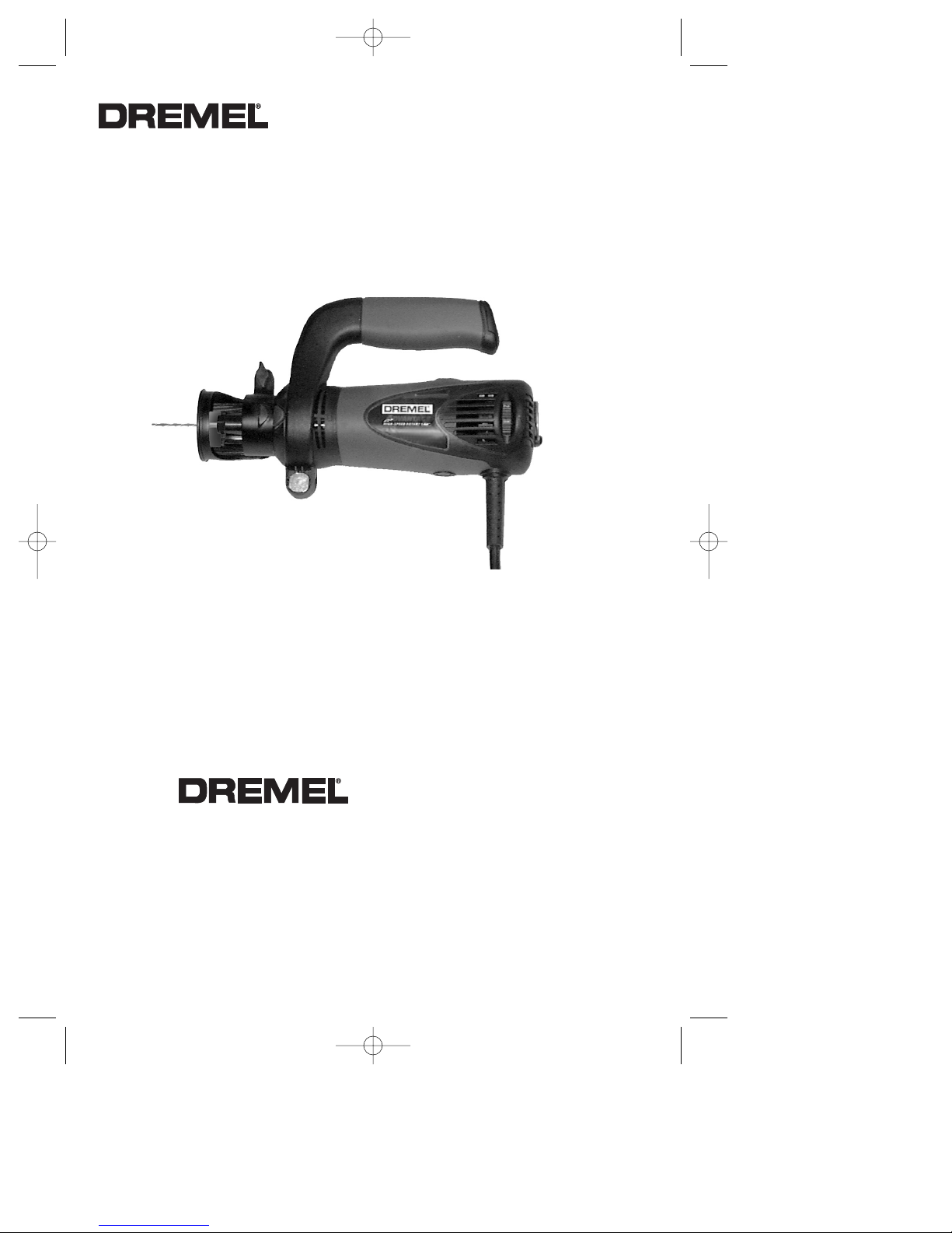
Owner’s Manual
ADVANTAGE
™
High Speed Rotary Saw
™
Model 9000
• Safety
• Descriptions
• Assembly
• Operation
• Maintenance and Service
• Warranty
2610930129 4/05 Printed in Mexico
P.O. Box 1468
Racine, Wisconsin 53401
1-800-437-3635
www.dremel.com
Parlez-vous français?
Voir page 13
¿Habla español?
Vea página 25
Dremel brand products are manufactured and sold by the
Dremel Division of Robert Bosch Tool Corporation
DM 2610930129 4-05 pt.1 4/4/05 9:29 PM Page 1

Page 2
Read and understand all instructions. Failure to follow all instructions listed
below, may result in electric shock, fire and/or serious personal injury.
SAVE THESE INSTRUCTIONS
Power Tool Safety Rules
Work Area
Keep your work area clean and well lit.
Cluttered benches and dark areas invite
accidents.
Do not operate power tools in explosive
atmospheres, such as in the presence of
flammable liquids, gases, or dust. Power
tools create sparks which may ignite the dust
or fumes.
Keep by-standers, children, and visitors
away while operating a power tool.
Distractions can cause you to lose control.
Electrical Safety
Double Insulated tools are equipped with
a polarized plug (one blade is wider than
the other.) This plug will fit in a polarized
outlet only one way. If the plug does not
fit fully in the outlet, reverse the plug. If it
still does not fit, contact a qualified
electrician to install a polarized outlet. Do
not change the plug in any way. Double
Insulation eliminates the need for the
three wire grounded power cord and
grounded power supply system.
Before
plugging in the tool, be certain the outlet
voltage supplied is within the voltage marked
on the nameplate. Do not use “AC only” rated
tools with a DC power supply.
Avoid body contact with grounded
surfaces such as pipes, radiators, ranges
and refrigerators. There is an increased risk
of electric shock if your body is grounded. If
operating the power tool in damp locations is
unavoidable, a Ground Fault Circuit Interrupter
must be used to supply the power to your tool.
Electrician’s rubber gloves and footwear will
further enhance your personal safety.
Don't expose power tools to rain or wet
conditions. Water entering a power tool will
increase the risk of electric shock.
Do not abuse the cord. Never use the cord
to carry the tools or pull the plug from an
outlet. Keep cord away from heat, oil, sharp
edges or moving parts. Replace damaged
cords immediately. Damaged cords increase
the risk of electric shock.
When operating a power tool outside, use
an outdoor extension cord marked "W-A"
or "W." These cords are rated for outdoor use
and reduce the risk of electric shock. Refer to
“Recommended sizes of Extension Cords” in
the Accessory section of this manual.
Personal Safety
Stay alert, watch what you are doing and
use common sense when operating a
power tool. Do not use tool while tired or
under the influence of drugs, alcohol, or
medication. A moment of inattention while
operating power tools may result in serious
personal injury.
Dress properly. Do not wear loose clothing
or jewelry. Contain long hair. Keep your
hair, clothing, and gloves away from
moving parts. Loose clothes, jewelry, or long
hair can be caught in moving parts. Keep
handles dry, clean and free from oil and
grease.
Avoid accidental starting. Be sure switch is
“OFF” before plugging in. Carrying tools with
your finger on the switch or plugging in tools
that have the switch “ON” invites accidents.
Remove adjusting keys or wrenches before
turning the tool “ON”. A wrench or a key that
is left attached to a rotating part of the tool may
result in personal injury.
Do not overreach. Keep proper footing and
balance at all times. Proper footing and
balance enables better control of the tool in
unexpected situations.
Use safety equipment. Always wear eye
protection. Dust mask, non-skid safety shoes,
hard hat, or hearing protection must be used
for appropriate conditions.
Tool Use and Care
Use clamps or other practical way to
secure and support the workpiece to a
stable platform. Holding the work by hand or
against your body is unstable and may lead to
loss of control.
Do not force tool. Use the correct tool for
your application. The correct tool will do the
job better and safer at the rate for which it is
designed.
!
WARNING
DM 2610930129 4-05 pt.1 4/4/05 9:29 PM Page 2

Page 3
Do not use tool if switch does not turn it
“ON” or “OFF”. Any tool that cannot be
controlled with the switch is dangerous and
must be repaired.
Disconnect the plug from the power source
before making any adjustments, changing
accessories, or storing the tool. Such
preventive safety measures reduce the risk of
starting the tool accidentally.
Store idle tools out of reach of children and
other untrained persons. Tools are
dangerous in the hands of untrained users.
Maintain tools with care. Keep cutting tools
sharp and clean. Properly maintained tools,
with sharp cutting edges are less likely to bind
and are easier to control. Any alteration or
modification is a misuse and may result in a
dangerous condition.
Check for misalignment or binding of
moving parts, breakage of parts, and any
other condition that may affect the tools
operation. If damaged, have the tool
serviced before using. Many accidents are
caused by poorly maintained tools. Develop a
periodic maintenance schedule for your tool.
Use only accessories that are recommended by the manufacturer for your
model. Accessories that may be suitable for
one tool, may become hazardous when used
on another tool.
Service
Tool service must be performed only by
qualified repair personnel. Service or
maintenance performed by unqualified
personnel could result in a risk of injury. For
example: internal wires may be misplaced or
pinched, safety guard return springs may be
improperly mounted.
When servicing a tool, use only identical
replacement parts. Follow instructions in
the Maintenance section of this manual.
Use of unauthorized parts or failure to follow
Maintenance Instructions may create a risk of
electric shock or injury. Certain cleaning
agents such as gasoline, carbon tetrachloride,
ammonia, etc. may damage plastic parts.
Rotary Saw Safety Rules
Hold tool by insulated gripping surfaces
when performing an operation where the
cutting tool may contact hidden wiring or
its own cord. Contact with a "live" wire will
make exposed metal parts of the tool "live"
and shock the operator.
If cutting into
existing walls or other blind areas where
electrical wiring may exist is unavoidable,
disconnect all fuses or circuit breakers
feeding this worksite.
Always make sure the work surface is
free from nails and other foreign objects.
Cutting into a nail can cause the bit and the
tool to jump and damage the bit.
Never hold the workpiece in one hand
and the tool in the other hand when in
use. Never place hands near or below
cutting surface. Clamping the material and
guiding the tool with both hands is safer.
Never lay workpiece on top of hard
surfaces, like concrete, stone, etc...
Protruding cutting bit may cause tool to jump.
Always wear safety goggles and dust
mask. Use only in well ventilated area.
Using personal safety devices and working in
safe environment reduces risk of injury.
After changing the bits or making any
adjustments, make sure the collet nut and
any other adjustment devices are
securely tightened. Loose adjustment
device can unexpectedly shift, causing loss
of control, loose rotating components will be
violently thrown.
Never start the tool when the bit is
engaged in the material. The bit cutting
edge may grab the material causing loss of
control of the cutter.
Always hold the tool with two hands
during start-up. The reaction torque of the
motor can cause the tool to twist.
The direction of feeding the bit into the
material is very important and it relates to
the direction of bit rotation. Most materials
should be cut in a clockwise direction. An
DM 2610930129 4-05 pt.1 4/4/05 9:29 PM Page 3
Page 4
exception is when cutting around an outlet
box in drywall, which should be cut counterclockwise. Steering the tool in the wrong
direction, causes the cutting edge of the bit
to climb out of the work and pull the tool in
the direction of the feed.
Never use dull or damaged bits. Sharp
bits must be handled with care. Damaged
bits can snap during use. Dull bits require
more force to push the tool, possibly causing
the bit to break.
Never touch the bit during or immediately
after the use. After use the bit is too hot to
be touched by bare hands.
Never lay the tool down until the motor
has come to a complete standstill. The
spinning bit can grab the surface and pull the
tool out of your control.
Never use bits that have a cutting
diameter greater than the opening in the
base.
Do not use the tool for drilling purposes.
This tool is not intended to be used with drill
bits.
Some dust created by
power sanding, sawing,
grinding, drilling, and other construction
activities contains chemicals known to
cause cancer, birth defects or other
reproductive harm. Some examples of
these chemicals are:
• Lead from lead-based paints,
• Crystalline silica from bricks and cement
and other masonry products, and
• Arsenic and chromium from chemically-
treated lumber.
Your risk from these exposures varies,
depending on how often you do this type of
work. To reduce your exposure to these
chemicals: work in a well ventilated area, and
work with approved safety equipment, such
as those dust masks that are specially
designed to filter out microscopic particles.
Always use the tool with the depth guide
securely attached and positioned flat
against material being cut. The guide
securely positioned on the material improves
the stability and control of your tool.
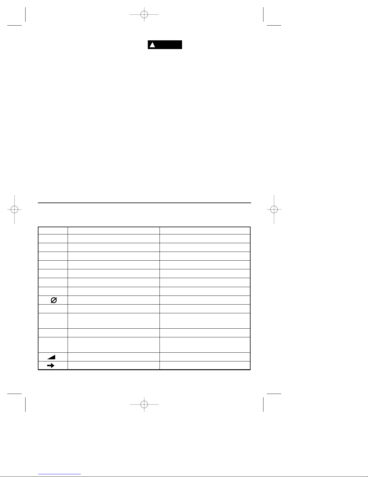
Symbols
IMPORTANT: Some of the following symbols may be used on your tool. Please study them
and learn their meaning. Proper interpretation of these symbols will allow you to operate the
tool better and safer.
Symbol Name Designation/Explanation
V Volts Voltage (potential)
A Amperes Current
Hz Hertz Frequency (cycles per second)
W Watt Power
kg Kilograms Weight
min Minutes Time
s Seconds Time
Diameter Size of drill bits, grinding wheels, etc.
n
0
No load speed Rotational speed, at no load
.../min Revolutions or reciprocation per minute Revolutions, strokes, surface speed,
orbits etc. per minute
0 Off position Zero speed, zero torque...
1, 2, 3, ... Selector settings Speed, torque or position settings.
I, II, III, Higher number means greater speed
Infinitely variable selector with off Speed is increasing from 0 setting
Arrow Action in the direction of arrow
0
!
WARNING
DM 2610930129 4-05 pt.1 4/4/05 9:29 PM Page 4
Model number 9000
Voltage rating 120V 50 - 60Hz
Amperage rating 4.5 A
No load speed n0 10,000-35,000/min
Collet capacities 1/8", 1/4"
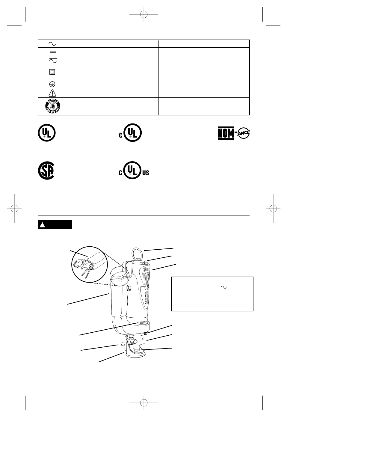
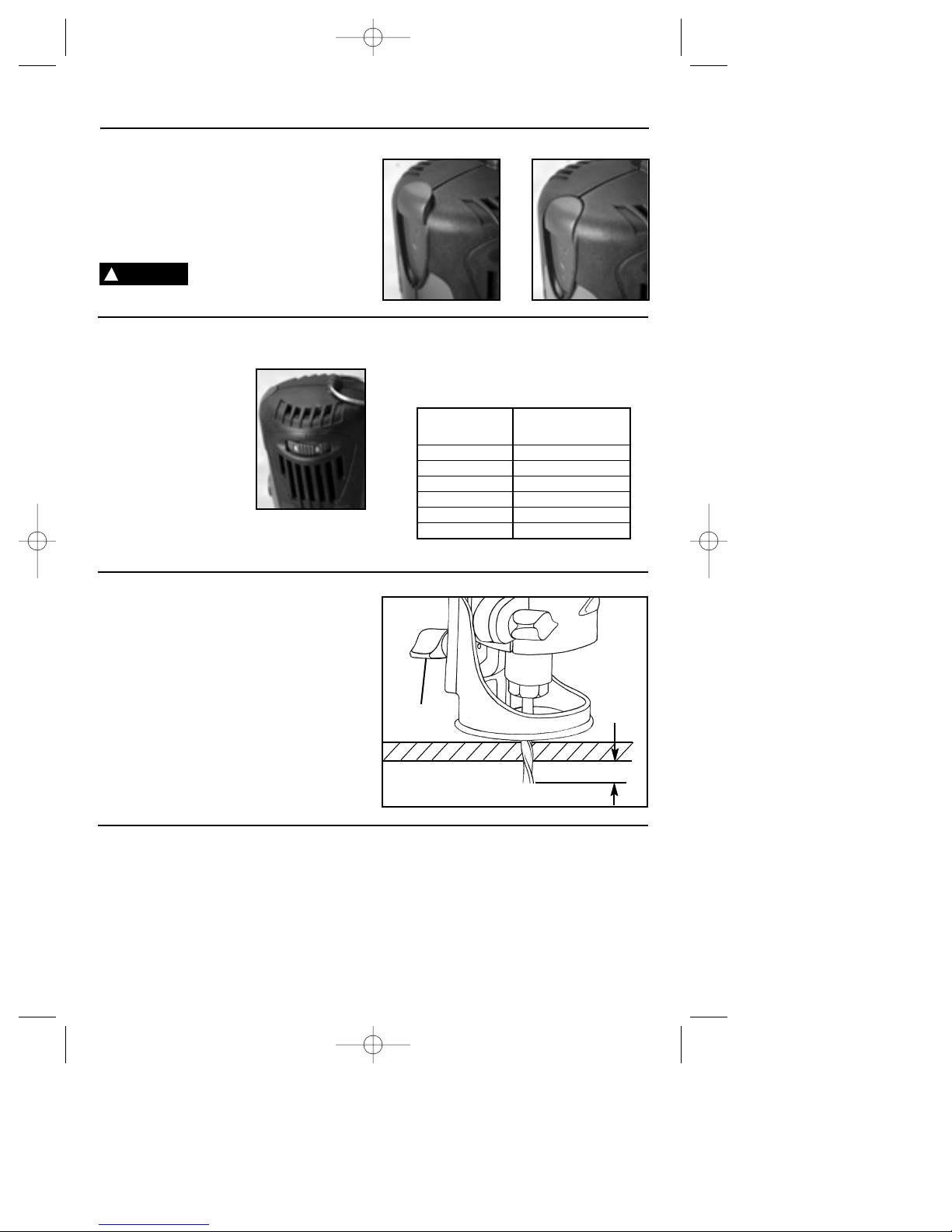
Functional Description and Specifications
SPEED DIAL
SHAFT LOCK
INTAKE AIR VENTS
HANG BAIL
DEPTH GUIDE
DEPTH GUIDE BRACKET
COLLET NUT
Disconnect the plug from the power source before making any
assembly, adjustments or changing accessories. Such preventive safety
measures reduce the risk of starting the tool accidentally.
Alternating current Type or a characteristic of current
Direct current Type or a characteristic of current
Alternating or direct current Type or a characteristic of current
Class II construction Designates Double Insulated
Construction tools.
Earthing terminal Grounding terminal
Warning symbol Alerts user to warning messages
Ni-Cad RBRC seal Designates Ni-Cad battery recycling
program
This symbol designates
that this tool is listed by
Underwriters Laboratories.
This symbol designates
that this tool is listed by
the Canadian Standards
Association.
This symbol designates
that this tool is listed to
Canadian Standards by
Underwriters Laboratories.
This symbol
designates
that
this tool
complies
to NOM
Mexican
Standards.
This symbol designates that
this tool is listed by
Underwriters Laboratories,
and listed to Canadian
Standards by Underwriters
Laboratories.
Page 5
AUXILIARY
HANDLE
TOOL
STORAGE
EXHAUST
AIR VENTS
DEPTH GUIDE
LOCKING WINGNUT
!
WARNING
DM 2610930129 4-05 pt.1 4/5/05 1:44 AM Page 5
Make certain that the collet
nut is securely tightened,
auxiliary handle and the depth guide are
installed properly before turning the tool
on.
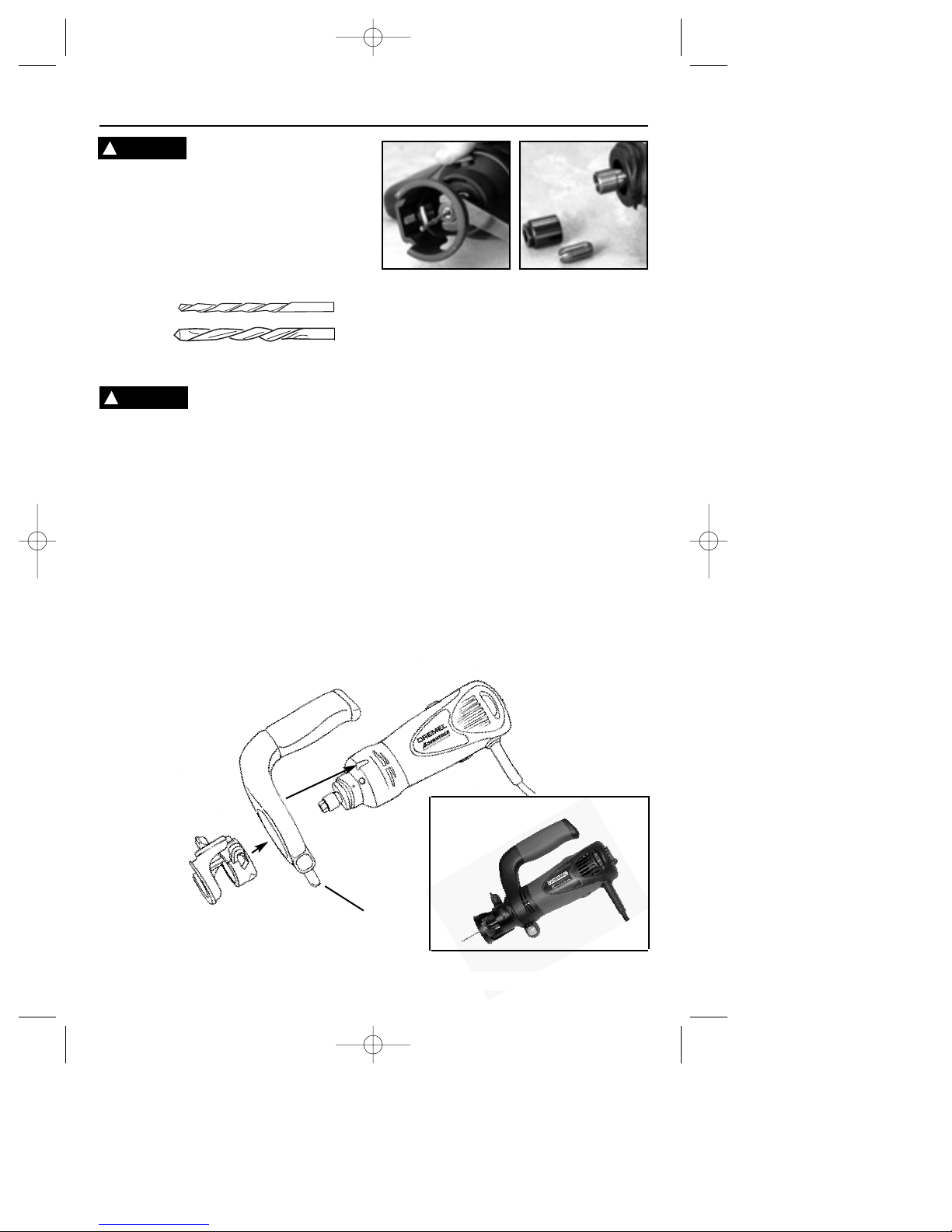
INSTALLING BITS
The bits are held by a collet system. Use
either a 1/8" or 1/4" collet (not included)
depending on the size of the bit shank.
The bit flutes are sharp and
should be handled with
caution.
Depress and hold the shaft-lock in and rotate
the collet nut and shaft until the shaft-lock
engages and holds the shaft. Use the
standard equipment wrench to loosen nut
(counter-clockwise). Remove the old bit (if
there is one) insert the new bit as far as
possible, but not so far that the bit flutes
engage the collet (leave approximately 1/8"
of shank exposed). Re-engage the shaft-lock
and tighten the nut (clockwise) by hand and
then with the wrench until bit is held securely.
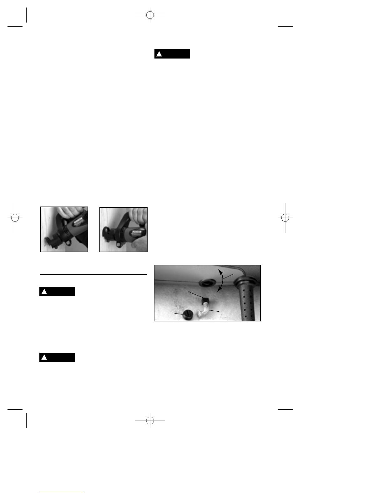
REMOVING AND INSTALLING DEPTH
GUIDE ASSEMBLY
The depth guide assembly consists of the
depth guide and depth guide bracket. To
detach, loosen the bracket nut and twist the
whole assembly 1/4 turn and pull straight off
the tool. To reattach the assembly, align the
two pegs inside the bracket with the grooves
on the tool collar and twist 1/4 turn, then
tighten the bracket nut.
REMOVING AND INSTALLING
AUXILIARY HANDLE
To remove, first detach the depth guide
assembly. Then release the locking lever and
pull handle off tool. To install the handle, first
detach the depth guide assembly. Align the
two wedges inside the handle with the two
notches on the housing and slide the handle
onto the housing until fully seated. Flip the
lever closed.
Assembly
1/8"
1/4"
(not included)
Handle slides onto notches
LOCKING LEVER
Removing and installing the handle
Tool with
handle
!
WARNING
!
WARNING
Page 6
DM 2610930129 4-05 pt.1 4/4/05 9:29 PM Page 6
Page 7
Operating Instructions
SLIDE "ON/OFF" SWITCH
This tool is switched "ON" by the slide switch
located on the top of the motor housing.
TO TURN THE TOOL "ON" slide the switch
button up.
TO TURN THE TOOL "OFF" slide the switch
button down or "0" position.
Hold the tool with both hands
while starting, since torque
from the motor can cause the tool to twist.
VARIABLE SPEED CONTROL
The variable speed control feature allows
motor speed to be
matched to cutter size
and material hardness for
improved finish, extended
bit life, and h i g h e r
performance. Speed
changes are achieved b y
ro tating Control Dial
RIGHT to increase speed,
LEFT to decrease as
indicated on housing (Fig.
1). Speed may be changed while tool is on.
The reference numbers on the dial facilitate
re-setting control to desired speed.
DEPTH GUIDE ADJUSTMENT
Use the depth guide to adjust the depth of
cut. Simply loosen (counter clockwise) the
wingnut a little (approximately 1/8 turn) and
slide the depth guide in or out to the desired
depth of cut (about 1/8" greater than material
thickness) and retighten the wingnut
(clockwise).
Speed Dial Approximate
Setting Speed (RPM)
1 10,000
2 18,000
3 23,000
4 27,000
5 31,000
6 35,000
“ON”
The chart below indicates the approximate
speed (RPM) of the tool at the dial settings.
Use the arrow next to the dial to select the
desired speed.
“OFF”
wingnut
MAKING DRYWALL CUT-OUTS
After assembling the bit into the tool as
described earlier, it will be necessary to
review the instructions provided below and
make some practice cut-outs with this tool
before attempting an actual job. The best
method is to take some scrap pieces and
nail or screw them in place over wall studs
which have an electrical box or other feature
in place. A few such exercises will give you
the necessary practice to make clean,
professional cutouts around whatever is
behind the drywall you are installing.
!
WARNING
1/8”
DM 2610930129 4-05 pt.1 4/4/05 9:29 PM Page 7
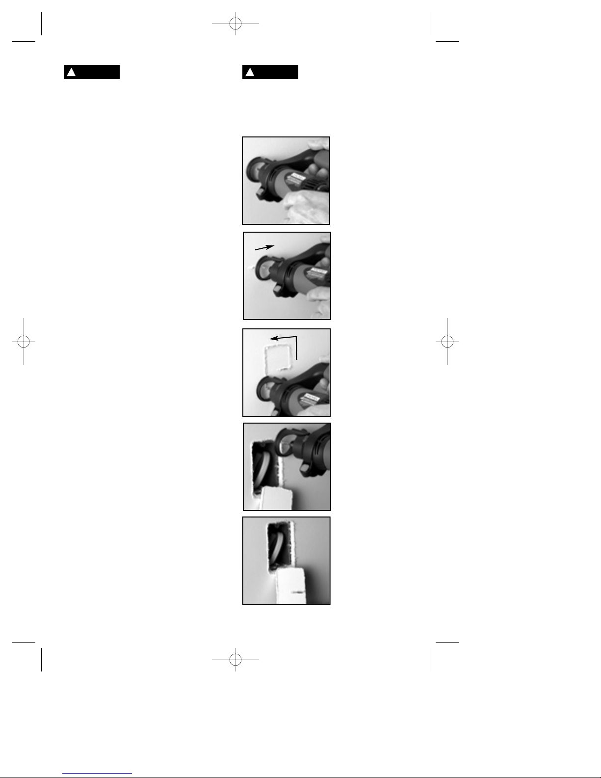
Do not attempt to use this
tool to make cut-outs
around any fixture or opening which has
live electrical wires, or on any wall which
may have live electrical wiring behind it,
as the bit could conduct current to the
tool, creating an electrocution hazard for
the operator. Shut off breakers or remove
fuses to disconnect the circuit. Always hold
the tool by its thermoplastic housing, and
always wear eye protection when operating
this device.
• Step 1: Be certain that the box or fixture
which requires a cut-out is firmly mounted
and all wires or other obstructions around the
opening are pushed back out of the way. The
drywall cut-out bit uses the outer edge of the
box or fixture as a guide, so it is important
that there is nothing in the way which can
prevent it from guiding completely around the
opening. For the purposes of this instruction
manual, the procedure discussed will be to
make a cut-out around a standard 2 1/8" x 3
3/4" electrical box.
• Step 2: Before fastening the drywall sheet,
make a mark close to the center of the
opening in the box on the side of the drywall
facing you. You may then begin to screw or
nail the sheet to the wall, but do not install
fasteners closer then about 15" to the box, or
the sheet will likely bulge and crack before
you cut the opening.
• Step 3: Holding the tool firmly switch the
tool to the "ON" position as described earlier.
• Step 4: Holding the tool firmly with both
hands, push the bit through the drywall at the
mark you made in step 2. Guide the bit to the
right until you feel it make contact with the
inside edge of the box. Then retract the bit
slightly, (do not pull entirely out) to allow it to
penetrate through the drywall and contact the
outside edge of the box by continuing to
move the tool slightly to the right as you cut.
• Step 5: Keeping the bit in contact with the
outside of the box, move the tool counterclockwise to create the opening. When
rounding a corner, keep applying light
pressure towards the center of the box while
moving the bit steadily and smoothly around
the whole box until the entire cut has been
completed. Slide the switch to the "OFF"
position, and pull the bit free of the drywall.
You may then remove the piece you have
cut, and you will have a smooth opening. The
rest of the screws or nails may now be put in
place on the drywall sheet, and the task is
completed.
The motor may stall if
improperly used or overloaded. Reduce the pressure or feed rate to
prevent possible damage to the tool. Do not
attempt to start the tool when the bit is
engaged in the workpiece. Always be sure the
collet nut is tightened securely before use.
Page 8
!
WARNING
!
CAUTION
DM 2610930129 4-05 pt.1 4/4/05 9:29 PM Page 8
Page 9
MAKING CUT-OUTS IN MATERIALS
OTHER THAN DRYWALL
Your tool is capable of cutting many types of
building materials in addition to drywall.
There are several different bits available for
use on these materials. Most materials can
be cut with the "multipurpose" bit, however
the "carbide" burr bits must be used for hard,
abrasive materials such as ceramic wall tile
(will not work on ceramic floor grade tile),
cement board, plaster etc.
To make cut-outs, insert and adjust the
proper bit according to previous instructions.
Hold the tool firmly and turn it on. Place the
depth guide at about a 45º angle against the
work surface and tilt the tool to an upright
position with the bit entering the scrap portion
of the area being cut. Move the bit to the line
you wish to follow and cut in a clockwise
direction. Cutting at a slow even rate will
make following a line easier and will put less
stress on the bit.
NOTE: When cutting on a vertical surface,
avoid ending your cut at the bottom of the
hole. If possible, start and end your cut at the
top so the scrap part will not drop onto the
rotating bit. Turn the tool off and remove it
from the cut out hole.
CLEANING
To avoid accidents always
disconnect the tool from the
power supply before cleaning or performing
any maintenance. The tool may be cleaned
most effectively with compressed dry air.
Always wear safety goggles when cleaning
tools with compressed air. Ventilation
openings and switch levers must be kept clean
and free of foreign matter. Do not attempt to
clean by inserting pointed objects through
openings.
Certain cleaning agents and
solvents damage plastic
parts. Some of these are: gasoline, carbon
tetrachloride, chlorinated cleaning solvents,
ammonia and household detergents that contain
ammonia.
SERVICE
Preventive maintenance pe-
rformed by unauthorized
personnel may result in misplacing of
internal wires and components which could
cause serious hazard. We recommend that all
tool service be performed by a Dremel Service
Facility.
CARBON BRUSHES
The brushes and commutator in your tool have
been engineered for many hours of dependable
service. To maintain peak efficiency of the
motor, we recommend every two to six months
the brushes be examined. Only genuine Dremel
replacement brushes specially designed for
your tool should be used.
MAINTENANCE OF REPLACEABLE
BRUSHES Model 9000
The brushes should be inspected frequently
when tools are used continuously. If your tool
runs sporadically, loses power, makes unusual
noises or runs at a reduced speed, check the
brushes. To continue using the tool in this
condition will permanently damage your tool.
With the cord unplugged, remove the brush
caps one at a time with a small screwdriver by
rotating cap counter-clockwise and check each
brush.
If the brush is less than 1/4" long and the end
surface of the brush that contacts the
commutator is rough and/or pitted, they should
be replaced. Check both brushes. Usually the
brushes will not wear out simultaneously. If one
brush is worn out, replace both brushes. Make
sure the brushes are installed as illustrated. The
curved surface of the brush must match the
curvature of the commutator.
After replacing brushes the tool should be run at
no-load; place it on a clean surface and run it
freely for 5 minutes before loading (or using) the
tool. This will allow the brushes to “seat”
properly and will give you more hours of life
from each set of brushes. This will also extend
the total life of your tool since the commutator
surface will “wear” longer.
Bearings - Model 9000 is equipped with ball
bearing construction. Under normal use no
additional lubrication is required.
!
CAUTION
Maintenance Information
!
WARNING
CURVATURE
OF HOUSING
BRUSH
CAP
CURVED END OF
BRUSH MUST
MATCH CURVATURE
OF HOUSING
BRUSH &
SPRING
ASSEMBLY
!
WARNING
DM 2610930129 4-05 pt.1 4/4/05 9:29 PM Page 9
Page 10
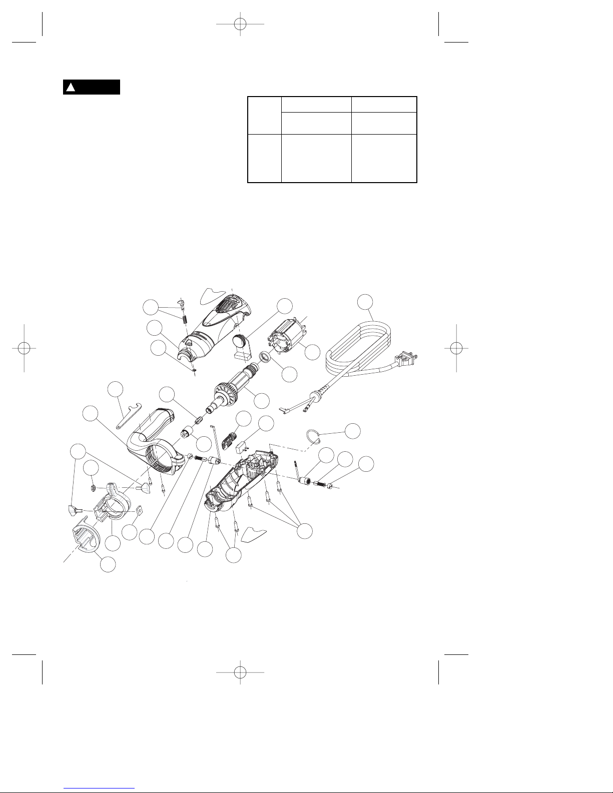
Dremel Advantage™ Service Parts Diagram
Tool’s
Ampere
Rating
Cord Size in A.W.G.
Wire Sizes in mm
2
3-6
6-8
8-10
10-12
12-16
18 16 16 14 0.75 0.75 1.5 2.5
18 16 14 12 0.75 1.0 2.5 4.0
18 16 14 12 0.75 1.0 2.5 4.0
16 16 14 12 1.0 2.5 4.0 —
14 12 — — — — — —
25 50 100 150 15 30 60 120
Cord Length in Feet Cord Length in Meters
RECOMMENDED SIZES OF EXTENSION
CORDS 120 VOLT ALTERNATING
CURRENT TOOLS
Extension Cords
If an extension cord is
necessary, a cord with
adequate size conductors that is capable
of carrying the current necessary for your
tool must be used. This will prevent
excessive voltage drop, loss of power or
overheating. Grounded tools must use 3-wire
extension cords that have 3-prong plugs and
receptacles.
NOTE: The smaller the gauge number, the
heavier the cord.
!
WARNING
DM 2610930129 4-05 pt.1 4/4/05 9:29 PM Page 10
9
24
10
8
23
2
5
7
6
15
18
21
19
16
20
13
12
17
25
11
3
11
4
1
12
14
24
22
22
Page 11
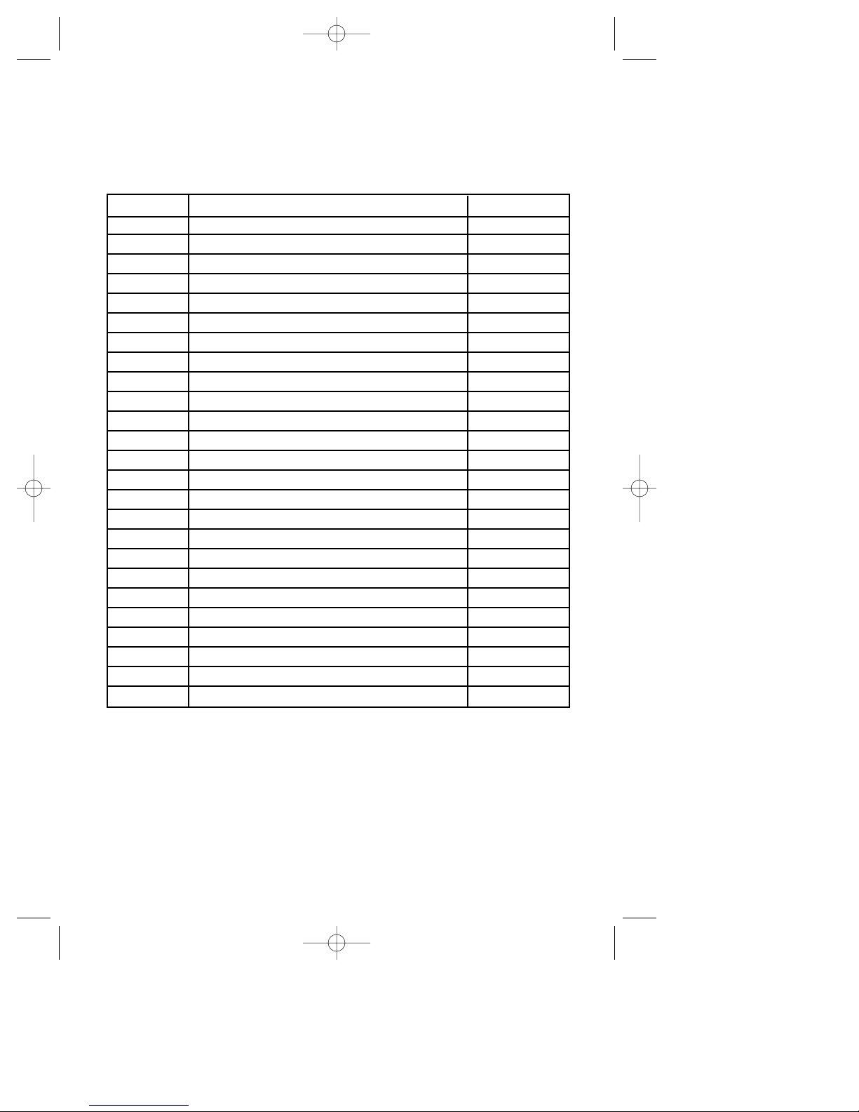
Ref. No. Part Part No.
1 Depth Guide Cutting Base Plate 2610916273
2 Depth Guide Wingnut (pair) 2610914431
3 Depth Guide Nut Plate 2610913184
4 Depth Guide Retainer 2610916274
5 Retainer nut 3603301505
6 Collet nut 2610913319
7 1/8" Collet 2615295093
8 Wrench 2615295097
9 Shaft lock assembly 2610907116
10 Shaft lock retaining ring 2610909201
11 Brush caps (pair) 2610913159
12 Motor brushes and springs (pair) 2610913160
13 Motor brush holder with straight lead 2610915244
14 Motor brush holder with right angle lead 2610915245
15 Cap for on/off switch 2610913156
16 On/off switch 2610996245
17 Power cord 2610913157
18 Speed control assembly 2610913155
19 Motor assembly 2610914664
20 Field assembly 2604220677
21 Rubber isolator ring 2615297373
22 Screws (five) 2610326578
23 Handle assembly 2610913023
24 Housing set with labels 2610907339
25 Tool hanger 2610913164
Order by part number, not reference number.
Write for current price or call 1-800-4 DREMEL
Dremel Advantage™
Service Parts List
DM 2610930129 4-05 pt.1 4/4/05 9:29 PM Page 11
 Loading...