

Page 1
Repair Instructions Service strategy
Repair Instructions
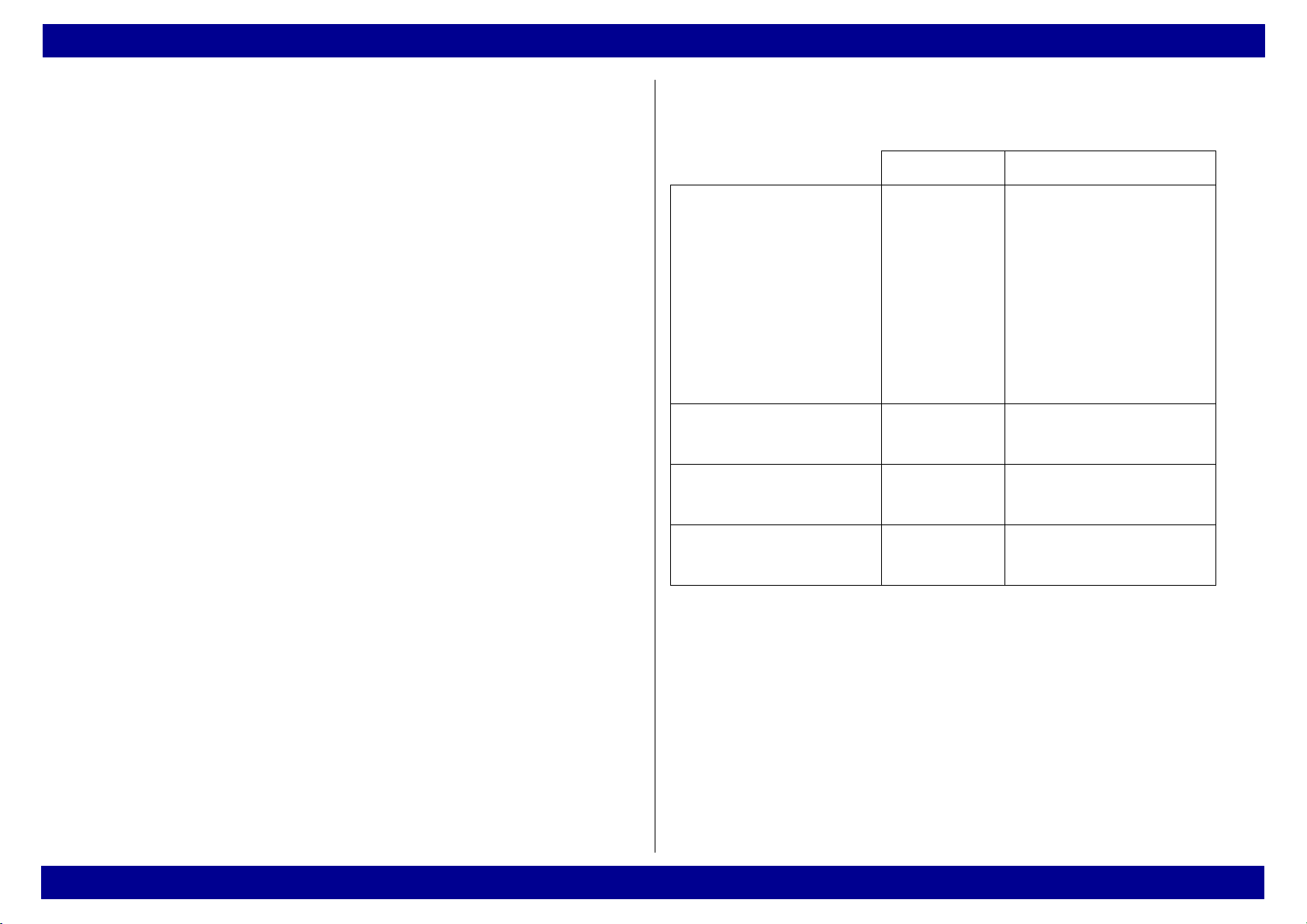
1 Service strategy
Test Repair
Inspection PMS
Procedure
On-site repair PMS
Procedure
Branch/Agency
(workshop)
Lübeck (workshop) PMS
PMS
Procedure
Procedure
Minor repair
Filter replacement,
if necessary
Hoses
Fuses
Assembly
replacement
Assembly
replacement
Assembly
replacement
All rights reserved. Copyright reserved • R5692200_Repair_Instructions_L2.fm 28.11.02 •
Dräger Medical AG & Co. KGaA • Medical Air Compressor •Version 2.0
1
Page 2
Repair Instructions Front view of the medical air compressor
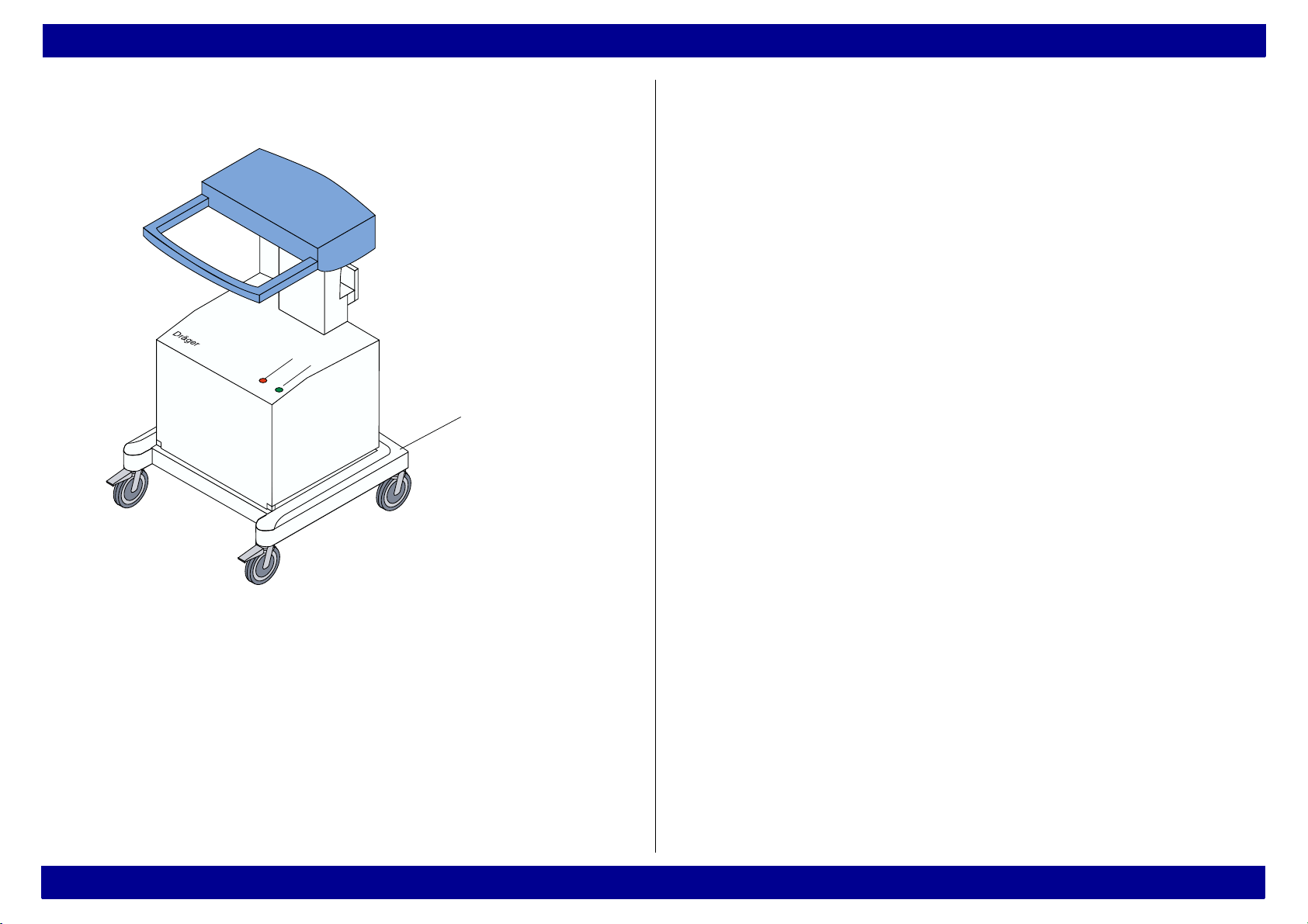
2 Front view of the medical air compressor
1
2
3
Fig. 1 Front view of the medical air compressor
All rights reserved. Copyright reserved • R5692200_Repair_Instructions_L2.fm 28.11.02 •
Legend
1 Red "Overheat" indicator lamp
2 Green "Standby" indicator lamp
3 Trolley
Dräger Medical AG & Co. KGaA • Medical Air Compressor •Version 2.0
2
Page 3
Repair Instructions Rear view of the medical air compressor
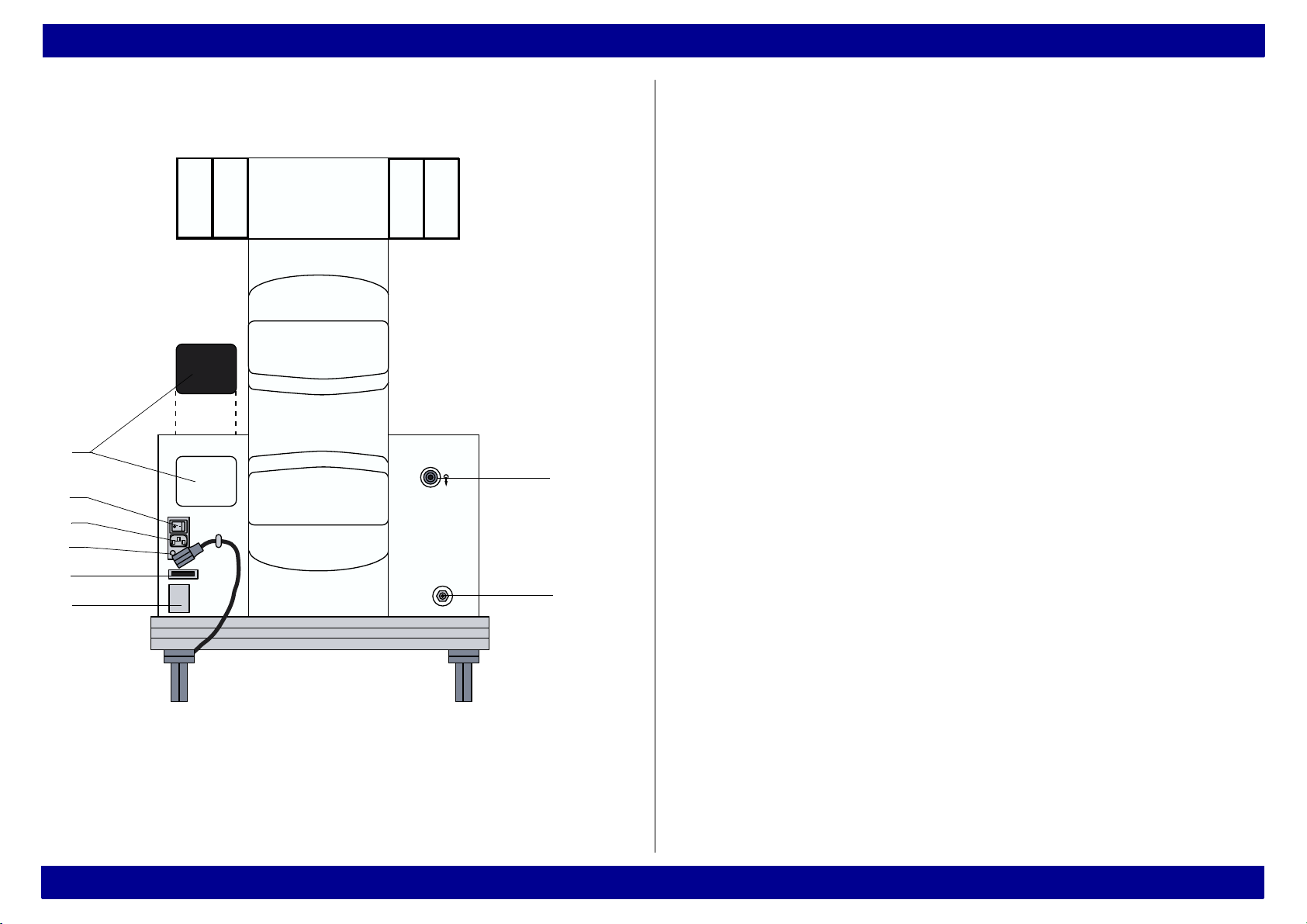
3 Rear view of the medical air compressor
8
1
7
6
5
Legend
1 Connection for a ventilator
2 Standby (optional connection for central supply
system)
3 Typeplate
4 Operating hours counter
5 Power fuses
6 Mains connection
7 ON/OFF switch
8 Suction channel with filter
4
3
All rights reserved. Copyright reserved • R5692200_Repair_Instructions_L2.fm 28.11.02 •
Fig. 2 Rear view of the medical air compressor
Dräger Medical AG & Co. KGaA • Medical Air Compressor •Version 2.0
2
3
Page 4
Repair Instructions Layout of the assemblies (1)
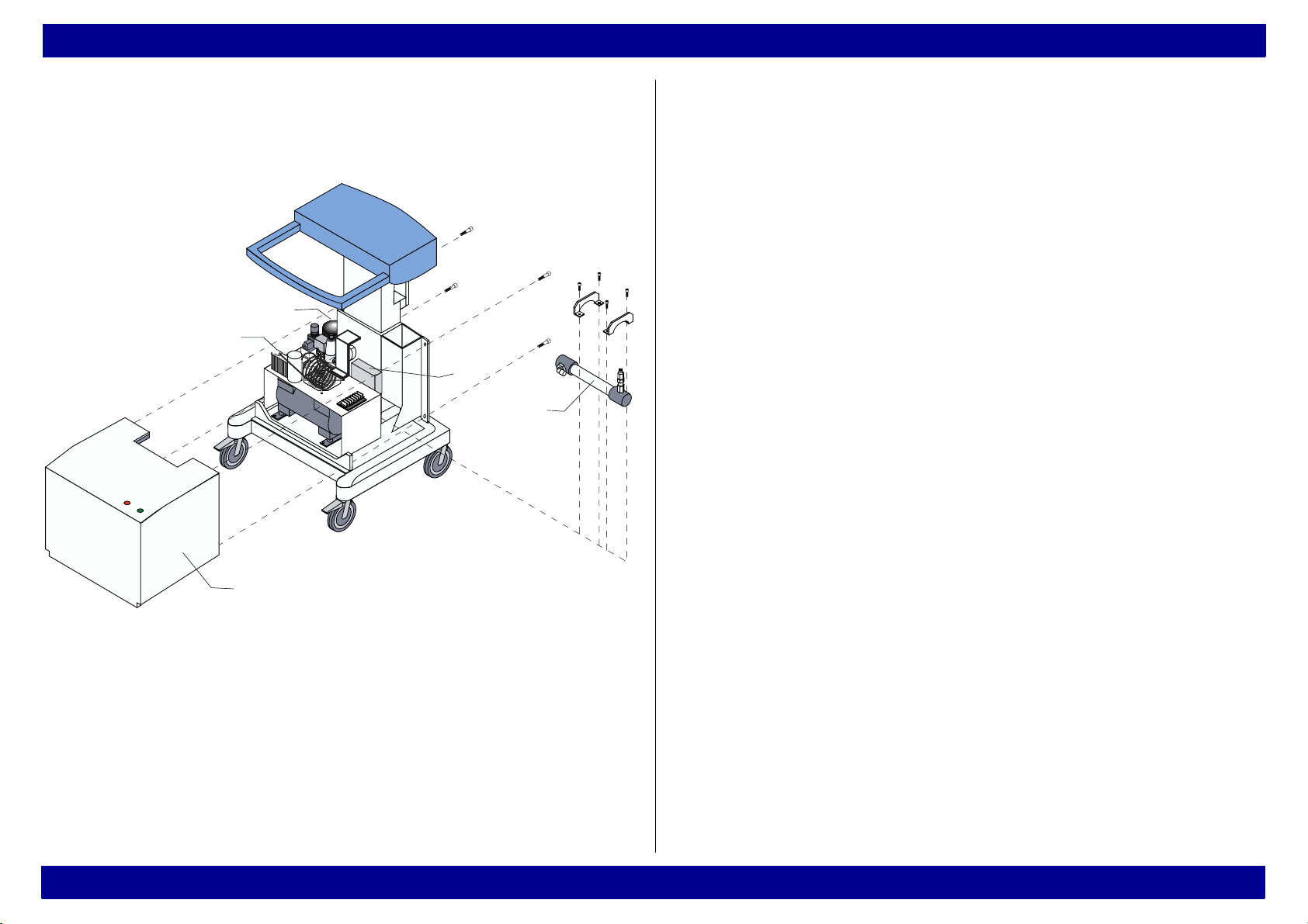
4 Layout of the assemblies (1)
3
2
D
Legend
1 Protective cover
2 Heat exchanger
4
4
4
3 Pressure vessel
4 Fixing screws
5 Diaphragm drier
4
6
5
6 Pressure switch (switchover optional)
1
All rights reserved. Copyright reserved • R5692200_Repair_Instructions_L2.fm 28.11.02 •
Fig. 3 Layout of the assemblies (1)
Dräger Medical AG & Co. KGaA • Medical Air Compressor •Version 2.0
4
Page 5
Repair Instructions Layout of the assemblies (2)
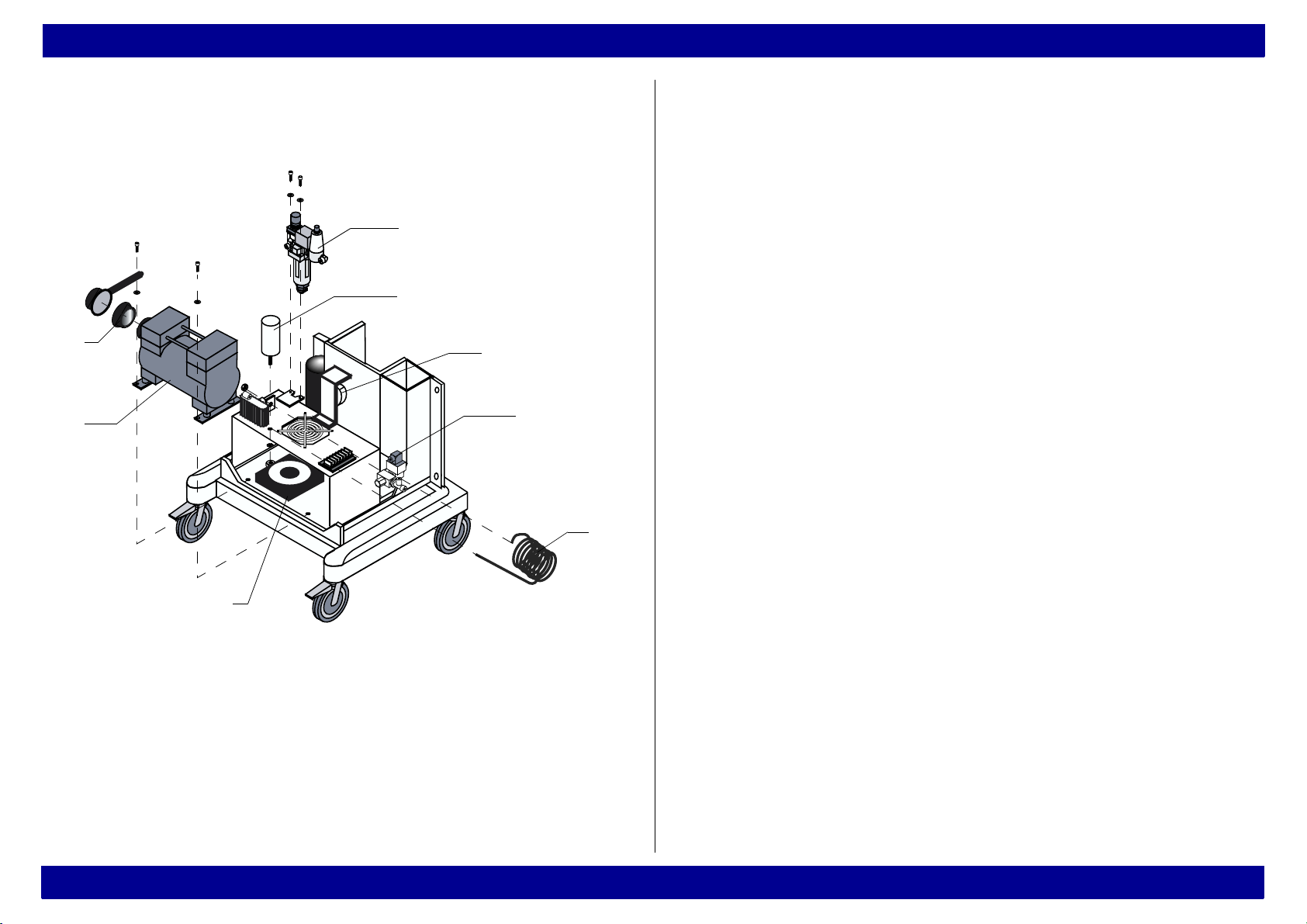
5 Layout of the assemblies (2)
3
4
2
1
Legend
1 Compressor
2 Suction filter
3 Filter assembly (prefilter and main filter)
4 Starting capacitor
5 Buzzer
6 Solenoid
5
7 Cooling coil
8Fan
6
7
8
All rights reserved. Copyright reserved • R5692200_Repair_Instructions_L2.fm 28.11.02 •
Fig. 4 Layout of the assemblies (2)
Dräger Medical AG & Co. KGaA • Medical Air Compressor •Version 2.0
5
Page 6

Repair Instructions Opening the medical air compressor
6 Opening the medical air compressor
Hazardous voltage. Touching live components can
lead to serious injury or death.
Pull the power plug out of the AC outlet before
opening the device.
1 Remove the fixing screws from the cover, see Fig. 3.
2 Carefully pull the protective cover back until the cable
of the indicator lamp can be accessed.
3 Unscrew the Phillips screw (Fig. 5/1) from the
connector.
4 Pull out the connector (Fig. 5/2).
5 Remove the protective cover completely.
1
All rights reserved. Copyright reserved • R5692200_Repair_Instructions_L2.fm 28.11.02 •
2
Fig. 5 Indicator lamp connector
Dräger Medical AG & Co. KGaA • Medical Air Compressor •Version 2.0
6
Page 7

Repair Instructions Replacing the filter sleeves of the prefilter and main filter
7 Replacing the filter sleeves of the prefilter
and main filter
The following replacement description of the prefilter
and main filter refers to the maintenance kit 84 11 546
(see also ”Change information” and PMS procedure).
For a replacement description of the new prefilter and
mainfilter (maintenance kit 84 14 501), see the
Instructions for Use under "Maintenance
intervals/Removing the filter group".
7.1 Removing the filter assembly
1 Unscrew fixing screws of protective cover, for fixing
screws see Fig. 3.
2 Open the unit, see 6.
3 Unscrew both Phillips screws (Fig. 6/1).
4 Push ring (Fig. 7/2) back and hold.
5 Remove hoses (Fig. 7/3).
6 Remove the filter assembly.
2
3
3
2
2
3
All rights reserved. Copyright reserved • R5692200_Repair_Instructions_L2.fm 28.11.02 •
1
1
Fig. 6 Removing the filter assembly
Dräger Medical AG & Co. KGaA • Medical Air Compressor •Version 2.0
Fig. 7 Removing the filter assembly
7
Page 8

Repair Instructions Replacing the filter sleeves of the prefilter and main filter
7.2 Replacing the filter sleeve of the prefilter
Prefilter
1 Unscrew housing (Fig. 9/1) by hand.
2 Unscrew clasp nut (Fig. 9/2).
3 Remove filter sleeve (Fig. 9/3) and replace with new
one.
4 Tighten clasp nut (Fig. 9/2).
5 Remove O-ring (Fig. 9/4) from housing and replace it
with a new one.
6 Tighten housing (Fig. 9/1) by hand.
Fig. 8 Prefilter
All rights reserved. Copyright reserved • R5692200_Repair_Instructions_L2.fm 28.11.02 •
Dräger Medical AG & Co. KGaA • Medical Air Compressor •Version 2.0
Fig. 9 Replacing the filter sleeve
8
Page 9

Repair Instructions Replacing the filter sleeves of the prefilter and main filter
7.3 Replacing the filter sleeve of the main filter
Main filter
Fig. 10Main filter
1 Pull interlock (Fig. 11/1) downwards and hold.
2 Rotate housing (Fig. 11/2) until markings (II) are
aligned.
3 Remove housing (Fig. 11/2).
1
2
Fig. 11Removing the main filter housing
All rights reserved. Copyright reserved • R5692200_Repair_Instructions_L2.fm 28.11.02 •
Dräger Medical AG & Co. KGaA • Medical Air Compressor •Version 2.0
9
Page 10

Repair Instructions Replacing the filter sleeves of the prefilter and main filter
4 Unscrew clasp nut (Fig. 12/4).
5 Remove filter sleeve (Fig. 12/3) and replace with new
one.
6 Tighten clasp nut (Fig. 12/4).
3
4
Fig. 12Replacing the filter sleeve
7 Remove O-ring (Fig. 13/5) from housing and replace it
with a new one.
5
Fig. 13O-ring of the main filter
All rights reserved. Copyright reserved • R5692200_Repair_Instructions_L2.fm 28.11.02 •
Dräger Medical AG & Co. KGaA • Medical Air Compressor •Version 2.0
10
Page 11

Repair Instructions Replacing the filter sleeves of the prefilter and main filter
8 Fit housing (Fig. 14/6) and rotate until markings (II) are
aligned and interlock (Fig. 14/7) engages audibly.
9 Pull housing (Fig. 14/6) slightly downwards to check
whether it is securely engaged.
7
6
Fig. 14Locking the main filter housing in place
All rights reserved. Copyright reserved • R5692200_Repair_Instructions_L2.fm 28.11.02 •
Dräger Medical AG & Co. KGaA • Medical Air Compressor •Version 2.0
11
Page 12

Repair Instructions Replacing the filter sleeves of the prefilter and main filter
7.4 Replacing the suction filter
1 Unscrew both Allen screws (Fig. 15/1).
2 Unscrew pressure hose (Fig. 15/2) using open-end
wrench WAF 19.
3 Pull compressor out until filter housing (Fig. 15/3)
becomes accessible.
4 Rotate filter housing (Fig. 15/3) clockwise and remove.
5 Remove suction filter (Fig. 15/4) and replace with new
one.
2
3
7.5 Fitting the filter assembly
Fit the filter assembly using the reverse method as
used for disassembly.
All rights reserved. Copyright reserved • R5692200_Repair_Instructions_L2.fm 28.11.02 •
1
3
Fig. 15Replacing the suction filter
6 Re-install the suction filter (Fig. 15/4).
7 Re-install the compressor.
Dräger Medical AG & Co. KGaA • Medical Air Compressor •Version 2.0
4
12
Page 13

Repair Instructions Standby switch of the medical air compressor (8413419)
8 Standby switch of the medical air
compressor (8413419)
8.1 Resetting the working pressure range
1 Set up a ventilator including test circuit.
2 Connect to gas supply.
3 Connect external pressure regulator/gauge to standby
inlet. (Gas inlet connector is located at rear panel in the
upper right area)
4 Connect the AIR central supply hose to the pressure
regulator hose.
Fig. 16Medical air compressor, open
5 Connect the AIR supply of the compressor/ventilator.
9 Connect ventilator and compressor to mains power
Do not connect to the O2 central supply. Do
not connect to mains power supply yet.
supply.
10 Switch compressor on.
11 Switch ventilator to standby mode and activate Service
6 Remove the four screws from the rear panel of the
Mode to monitor internal pressures.
All rights reserved. Copyright reserved • R5692200_Repair_Instructions_L2.fm 28.11.02 •
compressor.
12 Measure current switching points and set delta P to
7 Slide protective cover of compressor open (about 25
<15psi (<1 bar) (adjusting screws is located in the
cm).
lower portion of the switch).
8 Remove dark plastic cover from standby switch
(located directly behind the transformer on the right
side and is secured with 2 screws).
Dräger Medical AG & Co. KGaA • Medical Air Compressor •Version 2.0
13
Page 14

Repair Instructions Standby switch of the medical air compressor (8413419)
With compressors that were shipped world-wide,
proceed to work steps 13 to 17.
With compressors that were sold in the USA (as
of serial number ARSB-0001), proceed to work
steps 18 to 22.
13 Measure switching point and set starting pressure to 35
psi / 2.4 bar using external pressure regulator
(adjusting screw is located in the center portion of the
switch).
Compressor should start before the "AIR
supply insufficient" alarm is triggered.
14 Measure switching point and set switch-off pressure to
50 psi / 3.4 bar using external pressure regulator
(adjusting screw is located in the center portion of the
switch).
15 Check settings of starting pressure (35 psi / 2,4 bar)
and switch-off pressure (50 psi / 3,4 bar) under flow
conditions as specified in the PMS Procedure
(ventilator settings: CMV, flow max. (AutoFlow off) , Vt
max., rate 15, FiO2: 21).
16 Reassemble standby switch and compressor.
17 Remove external pressure regulator/gauge.
All rights reserved. Copyright reserved • R5692200_Repair_Instructions_L2.fm 28.11.02 •
Fig. 17Setting the working pressure
Dräger Medical AG & Co. KGaA • Medical Air Compressor •Version 2.0
18 Measure switching point and set starting pressure to 40
psi +
1.5psi (2.7 bar +0.1 bar) using external pressure
regulator (adjusting screw is located in the center
portion of the switch).
14
Page 15

Repair Instructions Standby switch of the medical air compressor (8413419)
20 Check settings of starting pressure (40 psi / 2.7 bar)
and switch-off pressure (46 psi / 3.2 bar) under flow
conditions as specified in the PMS procedure
(ventilator settings: CMV, flow max. (AutoFlow off) , Vt
max., rate 15, FiO2: 21).
21 Reassemble standby switch and compressor.
22 Remove external pressure regulator/gauge.
Fig. 18Setting the working pressure
Compressor should start before the "AIR supply
All rights reserved. Copyright reserved • R5692200_Repair_Instructions_L2.fm 28.11.02 •
insufficient" alarm is triggered.
19 Measure switching point and set switch-off pressure to
46 psi +
1.5 psi (3.2 bar +0.1 bar) using external
pressure regulator (adjusting screw is located in the
center portion of the switch).
Dräger Medical AG & Co. KGaA • Medical Air Compressor •Version 2.0
15
Page 16

Repair Instructions Change information
9 Change information
This change information is for information
only, built-in components are only replaced
with new versions in case of repair.
9.1 Prefilter housing
As of serial number ARML-0020, the prefilter housing
is made of metal.
9.2 Thermostat (part of starter relay 84 12 856)
To avoid frequent alarms, the thermostat has been set
from 40 °C to 75 °C. This change has been
implemented in devices from serial number ARMM0054 (84 13 900) or ARMN-0101 (84 13 419),
respectively.
Due to a change to the cable harness, only the green
110 V glow lamp is used in US compressors as of serial
number ARSB-0001.
9.4 Starter relay
The starter relay has been provided with a new timer.
This change has implemented in series units starting
with the following serial numbers: ARNJ-0088
(8413900), ARNJ-0017 (8413419), and ARNK-0031
(8413893).
9.5 Filter unit, new (84 14 502 / see also Service Bulletin no. 1)
To protect the diaphragm drier more efficiently, the filter
unit has been equipped with a finer fine filter. A new
maintenance kit is also available for the new filter unit.
This change has been implemented in series units
starting with serial number ARMJ-0020.
All rights reserved. Copyright reserved • R5692200_Repair_Instructions_L2.fm 28.11.02 •
9.3 Glow lamps
Due to a change in the circuit of 110 V compressors,
defective glow lamps will be replaced only with 230 V
glow lamps (Red glow lamp: 8413869, green glow
lamp: 8413870).
Dräger Medical AG & Co. KGaA • Medical Air Compressor •Version 2.0
Further information: According to Technical Service
Bulletin no. 1, this filter unit has to be replaced as well
when a faulty diaphragm drier is replaced (a notice to
do so has to be attached to the outside of the unit)
because the new maintenance kit, P/N 8413501, has to
be installed, too.
16
Page 17

Repair Instructions Change information
9.6 Standby, changed setting of working pressure range
The pressure range has been changed (as described
in the Repair Instructions, section 8) due to the
pressure supply of 3 bar available in different countries.
The pressure range has been changed in compressors
as of serial number ARPB-0001. At the same time, a
modified non-return valve (no spare part) has been
installed in the storage.
9.7 Registration of compressors
As of serial number ARPD-0001, compressors are
subject to registration. The units are shipped with new
Instructions for Use/Operating Instructions containing
the changed pressure settings.
All rights reserved. Copyright reserved • R5692200_Repair_Instructions_L2.fm 28.11.02 •
Dräger Medical AG & Co. KGaA • Medical Air Compressor •Version 2.0
17
 Loading...