

Drager Medical Air Compressor Repair Instructions

Dräger Medizintechnik
D
Contents
Repair Instructions
1 Service strategy 2
2 Front view of the medical air compressor 3
3 Rear view of the medical air compressor 4
4 Location of medical air compressor assemblies (1) 5
5 Location of medical air compressor assemblies (2) 6
6 Opening the medical air compressor 7
7 Replace the filter sleeves of the prefilter and main filter. 8
7.1 Removing the filter assembly ........................................................................................8
7.2 Replacing the prefilter sleeve ....................................................................................... 9
7.3 Replacing the main filter sleeve .................................................................................11
7.4 Replacing the suction filter ......................................................................................... 13
7.5 Installing the filter assembly ....................................................................................... 13
8 Standby switch of the medical air compressor (84 13 419) 14
8.1 Resetting the operating pressure range ..................................................................14
9 Change information 16
9.1 Prefilter housing ........................................................................................................... 16
9.2 Thermostat (part of starter relay 84 12 856) .......................................................... 16
9.3 Glow lamps .................................................................................................................... 16
R5692200T01IVZ.fm
9.4 Starter relay ................................................................................................................... 16
9.5 Filter unit, new (84 14 502 / see also Service Bulletin no. 1) ............................ 16
9.6 Standby, changed setting of operating pressure range .......................................17
9.7 Registration of compressors .......................................................................................17
For internal use only. Copyright reser ved.
5692.200 Medical Air Compressor09/00 Repair Instructions Page I
Repair Instructions
1 Service strategy
Test Re pair
Inspection Test Certificate Minor repair
Filter replacement, if
necessary
Tube s
Fuses
On-site repair Test Certificate Assembly replacement
Branch/Agency (workshop) Test Certificate Assembly replacement
Lübeck (workshop) Test Certificate Assembly replacement
R5692200T01.fm 08.11.00
For internal use only. Copyright reserved.
5692.200 Medical Air Compressor 09/00 Repair Instructions Page 2
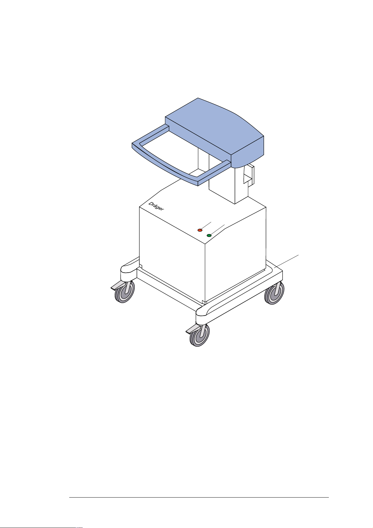
2 Front view of the medical air compressor
1
2
Fig. 1: Front view of the medical air compressor
Key
1 Red "Overheat" indicator lamp
2 Green "Standby" indicator lamp
3 Trolley
3
R5692200T01.fm 08.11.00
For internal use only. Copyright reserved.
5692.200 Medical Air Compressor 09/00 Repair Instructions Page 3
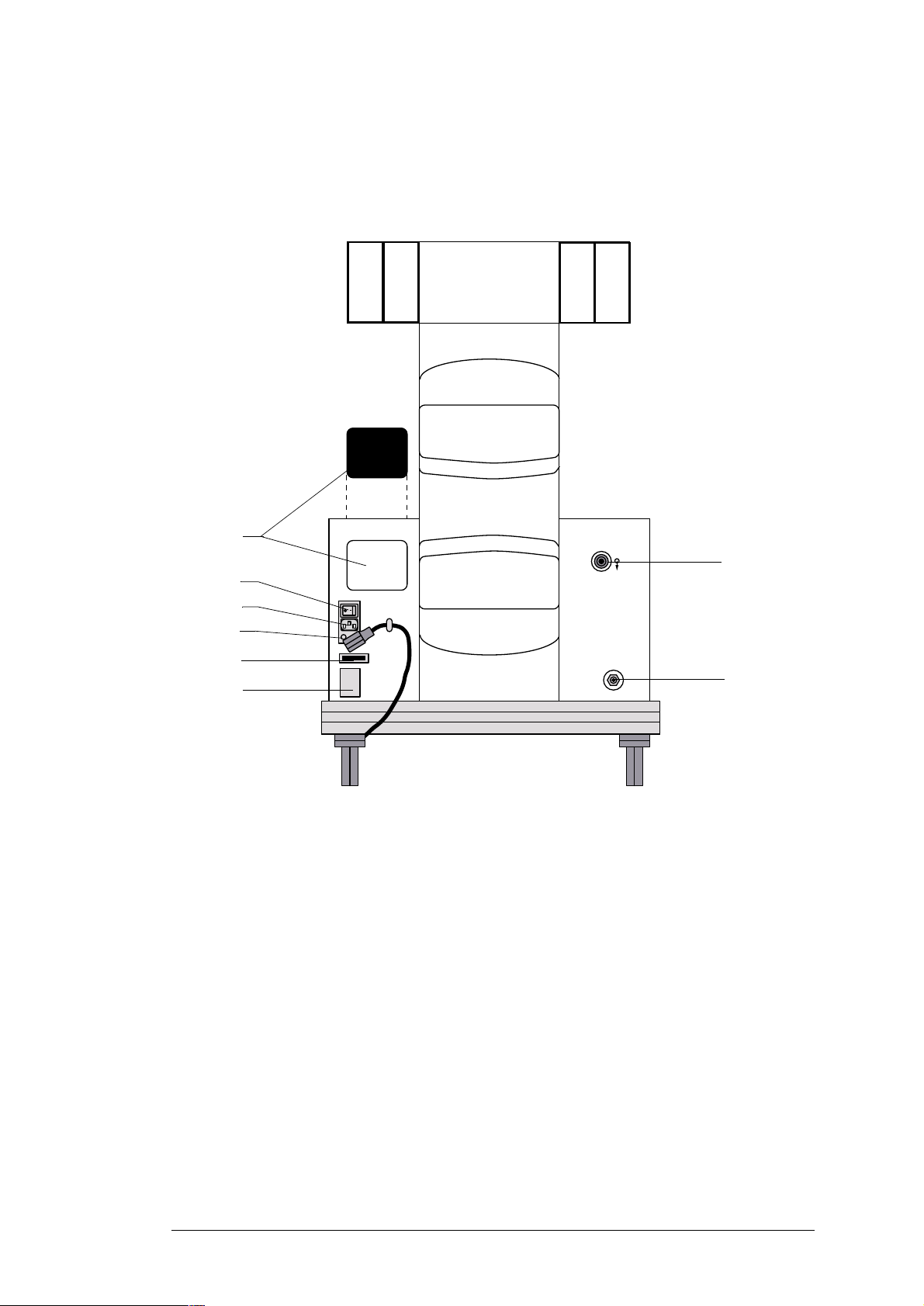
3 Rear view of the medical air compressor
8
7
6
5
1
4
3
Fig. 2: Rear view of the medical air compressor
Key
1 Connection for a ventilator
2 Standby (optional connection for central supply system)
3 Typeplate
4 Operating hours counter
5 Power fuses
6 Mains power connection
2
R5692200T01.fm 08.11.00
7 ON/OFF switch
8 Suction channel with filter
For internal use only. Copyright reserved.
5692.200 Medical Air Compressor 09/00 Repair Instructions Page 4
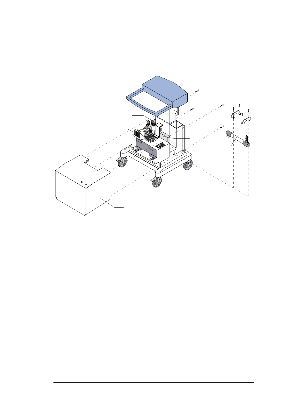
4 Location of medical air compressor assemblies (1)
4
4
3
2
6
D
4
4
5
1
Fig. 3: Location of medical air compressor assemblies (1)
Key
1 Protective cover 4 Fixing screws
2 Heat exchanger 5 Diaphragm drier
3 Pressure vessel 6 Pressure switch (switchover optional)
R5692200T01.fm 08.11.00
For internal use only. Copyright reserved.
5692.200 Medical Air Compressor 09/00 Repair Instructions Page 5
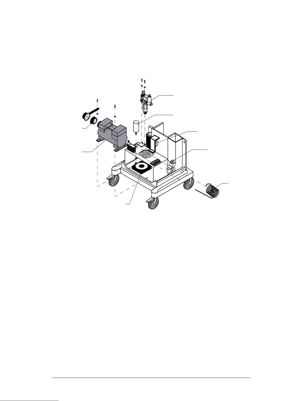
5 Location of medical air compressor assemblies (2)
3
4
2
1
8
Fig. 4: Location of medical air compressor assemblies (2)
Key
1 Compressor 5 Buzzer
2 Suction filter 6 Solenoid
5
6
7
R5692200T01.fm 08.11.00
3 Filter assembly (prefilter and main
7 Cooling coil
filter)
4 Starting capacitor 8 Fan
For internal use only. Copyright reserved.
5692.200 Medical Air Compressor 09/00 Repair Instructions Page 6
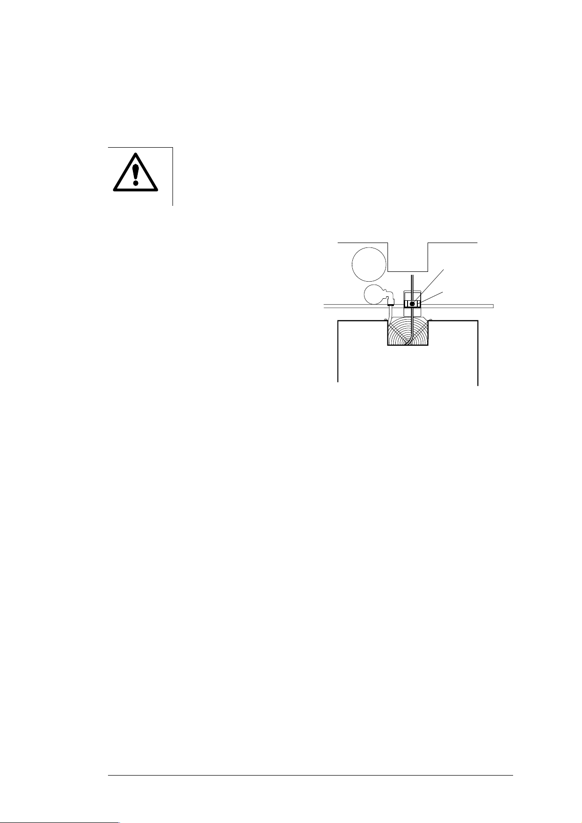
6 Opening the medical air compressor
Hazardous voltage. Touching live components can lead to serious injury or
death.
Pull the power plug out of the AC outlet before opening the device.
• Remove the fixing screws from the
cover (see "Location of medical air
compressor assemblies (1)" on page
5)
• Carefully pull the protective cover
back until the cable of the indicator
lamp can be accessed.
• Unscrew the Phillips screw 1 from the
connector.
• Remove the connector 2.
1
2
Remove the protective cover completely.
Fig. 5: Indicator lamp connector
R5692200T01.fm 08.11.00
For internal use only. Copyright reserved.
5692.200 Medical Air Compressor 09/00 Repair Instructions Page 7
 Loading...