

Page 1
Drager
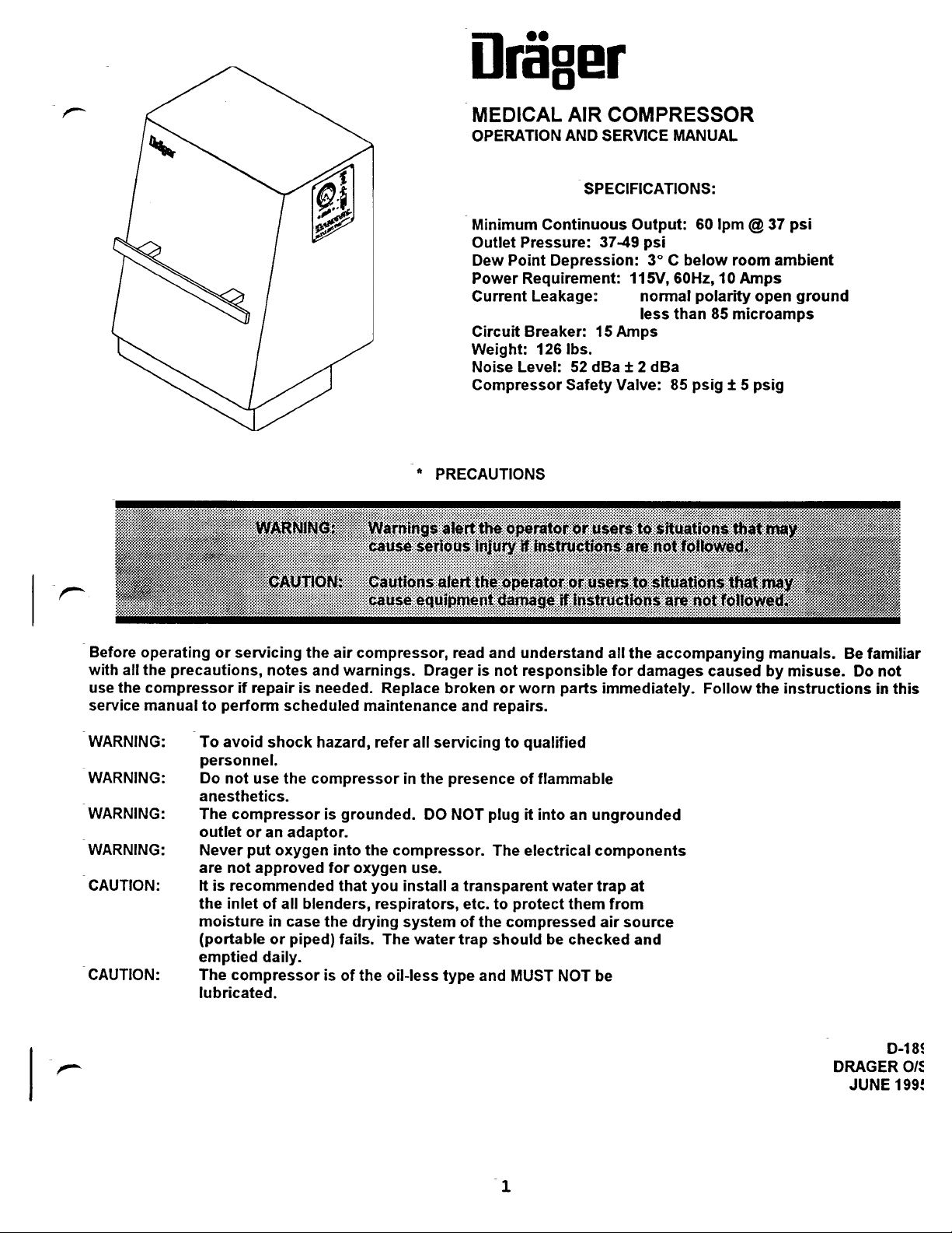
“MEDICAL
OPERATION
Minimum
Outlet
Dew
Power
Current
Circuit
Weight:
Noise
Compressor
*
PRECAUTIONS
AIR
AND
Continuous
Pressure:
Point
Depression:
Requirement:
Leakage:
Breaker:
126
Ibs.
Level:
52
Safety
COMPRESSOR
SERVICE
SPECIFICATIONS:
37-49
15
Amps
dBa + 2
Valve:
MANUAL
Output:
psi
3° C below
115V,
60Hz,
normal
less
than
dBa
85
psig t 5
60
Ipm © 37
room
10
Amps
polarity
85
microamps
ambient
open
psig
psi
ground
Before
with
all
use
the
service
WARNING:
-
WARNING:
-
WARNING:
WARNING:
-
CAUTION:
|
CAUTION:
operating
the
precautions,
compressor
manual
To
personnel.
Do
anesthetics.
The
outlet
Never
are
It
the
moisture
(portable
emptied
The
lubricated.
or
servicing
if
to
perform
avoid
not
compressor
not
is
recommended
inlet
compressor
notes
repair
scheduled
shock
use
the
or
an
adaptor.
put
oxygen
approved
of
all
in
case
or
daily.
the
air
and
is
needed.
hazard,
compressor
is
into
for
blenders,
the
piped)
is
compressor,
warnings.
Replace
maintenance
refer
grounded.
the
compressor.
oxygen
that
you
respirators,
drying
fails.
The
of
the
oil-less
read
and
understand
Drager
all
in
the
DO
use.
install a transparent
system
water
is
not
broken
and
repairs.
servicing
presence
NOT
plug
The
etc.
to
of
the
trap
should
type
and
responsible
or
worn
to
qualified
of
it
electrical
protect
compressed
MUST
parts
flammable
into
an
ungrounded
components
water
them
be
checked
NOT
be
all
the
accompanying
for
damages
immediately.
trap
at
from
air
source
and
caused
Follow
manuals.
by
misuse.
the
instructions
Be
familiar
Do
ОКАСЕК
JUNE
not
in
0-18
this
ОЛ
199!
Page 2
|
TABLE
OF
CONTENTS
ROUTINE
WEEKLY
QUARTERLY
YEARLY
BETWEEN
TROUBLE
A.
B.
C.
D.
E.
F.
-
SERVICE
A.
B.
EXTERNAL
A.
B.
REPLACEMENT
WIRING
SCHEMATIC
PNEUMATIC
MAINTENANCE
8000-9000
SHOOTING
PRESSURE
GAUGE
OVERHEATING
NOISE/EXCESSIVE
WATER
HIGH
LOW
TO
ADJUSTING
AIR
AIR
INSTALLING
PROBLEMS
PRESSURE
PRESSURE
If
the
If
the
CHECK
RESERVOIR
OUTLET
PARTS
compressor
compressor
FOR A FAULTY
THE
MODIFICATIONS
OPTIONAL
LIST
SCHEMATIC
HOURS
NEEDLE
VIBRATION
is
is
PRESSURE
KIT
EXTERNAL
STICKS
not
running
running
SOLENOID
SWITCH
ROUTINE
OR
VIBRATES
AIR
RESERVOIR
MAINTENANCE
KIT
NN
Mn
OO
Y“
Y“
Y
“Y
00
© © © ©
©
O
Note:
WEEKLY
Remove
and
the
reinstall.
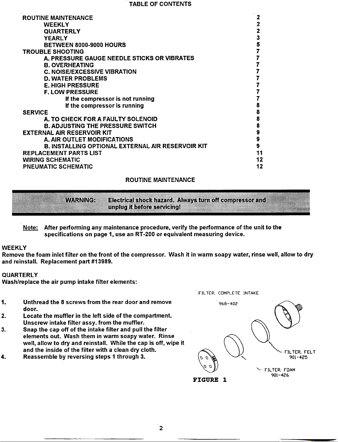
QUARTERLY
Wash/replace
1.
_Unthread
door.
Locate
Unscrew
Snap
elements
well,
and
4.
Reassemble
After
performing
specifications
foam
inlet
Replacement
the
air
pump
the 8 screws
the
muffler
intake
the
cap
out.
allow
to
the
inside
by
filter
part
intake
in
filter
off
of
the
Wash
dry
and
of
the
reversing
any
maintenance
on
page
on
the
front
#13989.
filter
from
the
the
left
side
assy.
from
intake
them
in
warm
reinstall.
filter
with a clean
steps 1 through
1,
use
of
the
elements:
rear
of
the
the
muffler.
filter
and
soapy
While
procedure,
an
RT-200
compressor.
door
and
compartment.
pull
the
water.
the
cap
is
dry
cloth.
3.
or
equivalent
remove
filter
Rinse
off,
verify
Wash
wipe
the
it
it
performance
measuring
in
warm
“FILTER,
FIGURE
device.
soapy
COMPLETE
968-402
i
of
the
water,
INTAKE
unit
rinse
—
to
the
well,
allow
“
FILTER,
901-426
to
FILTER,
901-425
FOAM
dry
FELT
Page 3
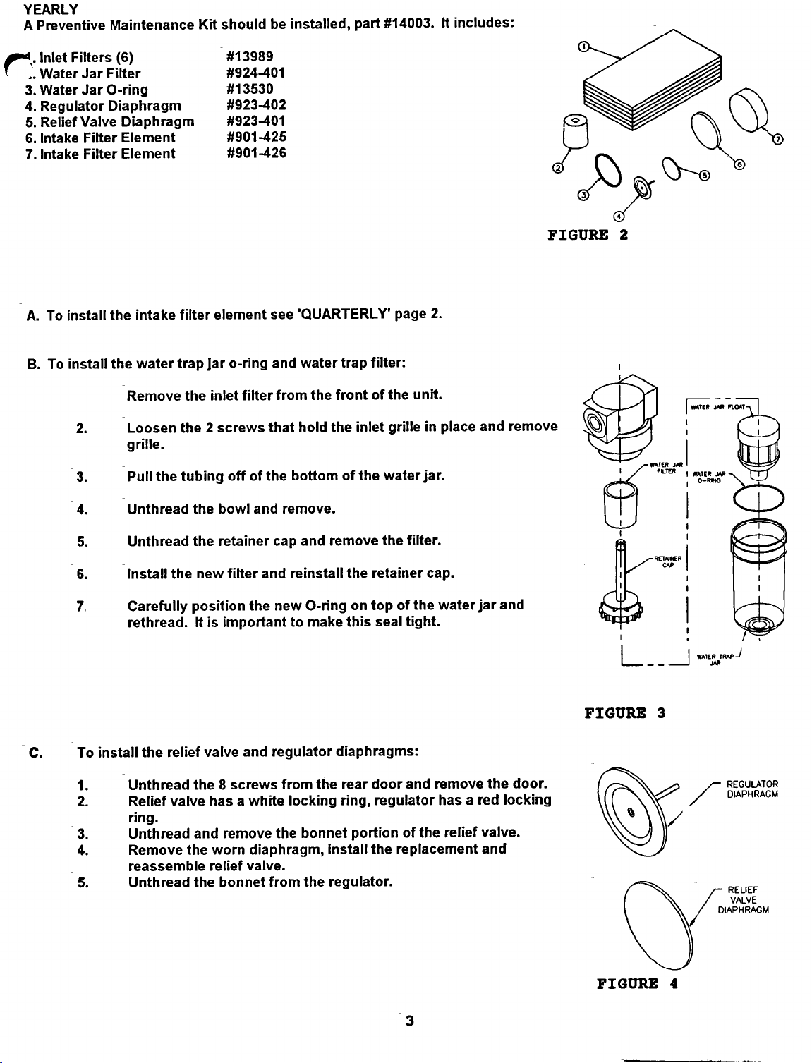
YEARLY
Preventive
A
|.
Inlet
..
Water
3.
Water
4.
Regulator
5.
Relief
6.
Intake
7.
Intake
Maintenance
Filters
Jar
Filter
Jar
O-ring
Diaphragm
Valve
Filter
Filter
(6)
Diaphragm
Element
Element
Kit
should
be
#13989
#924-401
#13530
#923-402
#923-401
#901-425
#901-426
installed,
part
#14003.
includes:
It
=
No
À,
A.
B.
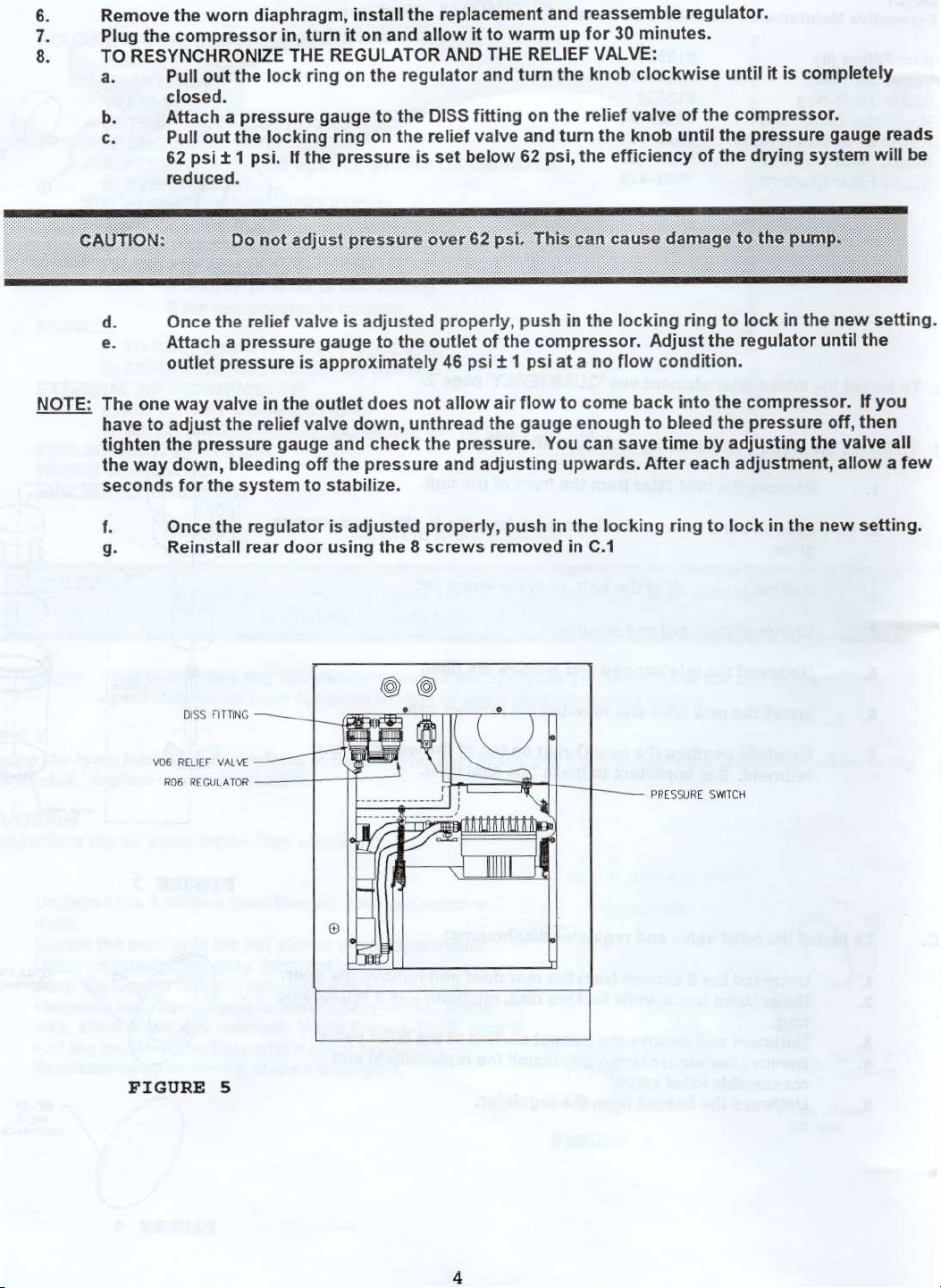
To
install
To
install
2.
3
4.
5
6
7
the
intake
the
water
‘Remove
‘Loosen
grille.
Pull
the
'Unthread
‘Unthread
Install
Carefully
rethread.
filter
element
trap
jar
o-ring
the
inlet
the 2 screws
tubing
the
off
the
bowl
the
retainer
new
filter
position
!t
is
important
see
and
filter
that
of
the
and
cap
and
the
new
'QUARTERLY'
water
from
the
hold
bottom
remove.
and
reinstall
O-ring
to
make
trap
front
the
inlet
of
the
remove
the
on
this
page
filter:
of
the
unit.
grille
water
the
filter.
retainer
top
of
the
seal
tight.
2.
in
jar.
cap.
place
water
and
jar
remove
and
FIGURE
2
©
“To
1
2.
|
3.
4.
.
5.
install
the
‘Unthread
Relief
ring.
Unthread
Remove
reassemble
Unthread
relief
valve
the 8 screws
valve
has a white
and
the
worm
relief
the
and
remove
diaphragm,
valve.
bonnet
regulator
from
the
locking
the
bonnet
from
the
diaphragms:
rear
door
ring,
regulator
portion
install
the
regulator.
and
remove
has a red
of
the
relief
replacement
the
door.
locking
valve.
and
L
FIGURE
O
FIGURE
ーー
=
mues
que)
3
Y
-
REGULATOR
DIAPHRAGM
RELIEF
VALVE
DIAPHRAGM
A
/
4
Page 4
6.
&
8.
Remove
Plug
the
TO
RESYNCHRONIZE
a.
b.
c.
the
worn
diaphragm,
compressor
out
Pull
closed.
Attach a pressure
Pull
out
+
psi
62
reduced.
the
the
psi.
1
in,
turn
THE
lock
locking
the
If
it
REGULATOR
on
ring
gauge
ring
pressure
install
on
the
on
and
to
the
regulator
the
the
replacement
allow
it
AND
and
DISS
fitting
relief
valve
below
set
is
to
THE
warm
RELIEF
turn
on
and
62
and
reassemble
up
for 30
knob
the
the
relief
turn
the
psi,
minutes.
VALVE:
clockwise
valve
the
knob
efficiency
regulator.
until
of
the
compressor.
until
the
pressure
drying
the
of
completely
is
it
system
gauge
reads
be
will
AA
CAUTION:
NOTE:
d.
e.
The
one
have
tighten
the
way
seconds
TE
3.
E
not
Do
©
Once
the
relief
Attach a pressure
outlet
to
the
Once
Reinstall
way
valve
adjust
pressure
down,
for
the
the
Diss
FITTING
pressure
the
relief
bleeding
system
regulator
rear
一 一
adjust
valve
is
in
the
valve
gauge
off
to
door
|
en
pressure
is
adjusted
gauge
approximately
outlet
to
the
does
down,
and
check
the
pressure
stabilize.
is
adjusted
using
the 8 screws
not
unthread
psi,
62
over
properly,
outlet
of
46 psi t 1
allow
air
the
the
pressure.
and
adjusting
properly,
removed
ne
This
push
the
compressor.
psi
flow
gauge
You
push
in
e
cause
can
in
the
at a no
to
come
enough
can
upwards.
the
locking
in
C.1
damage
locking
Adjust
flow
condition.
back
to
bleed
save
time
After
ring
LE
ring
the
into
by
each
to
the
to
P
to
lock
in
regulator
the
compressor.
the
pressure
adjusting
adjustment,
lock
in
pump.
the
new
until
off,
the
valve
allow a few
the
new
setting.
the
If
you
then
all
setting.
vo6
R06
FIGURE
REUEF
wLvE 一 一 一 |
REGULATOR
5
|
ーー
PRESSURE
SWITCH
Page 5
©
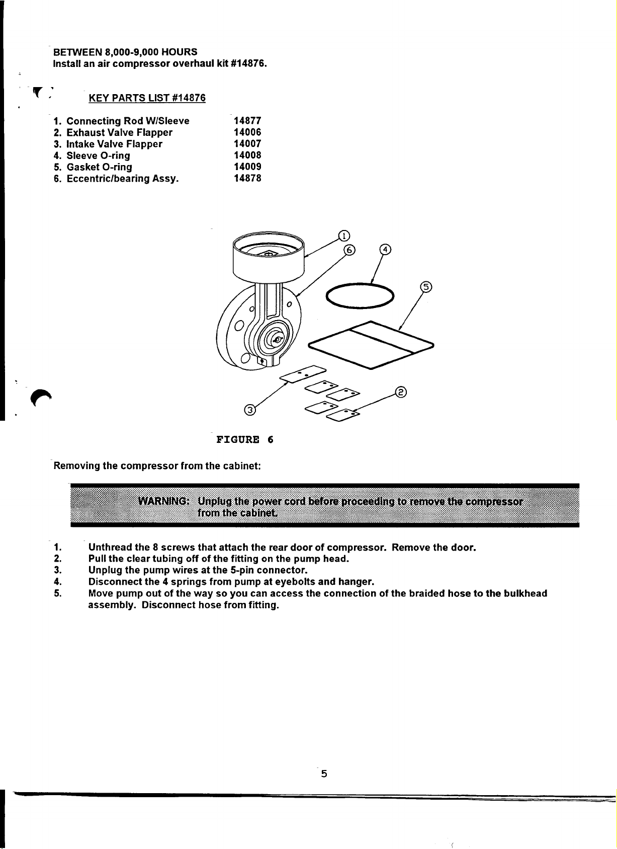
BETWEEN
Install
8,000-9,000
an
air
compressor
HOURS
overhaul
kit
#14876.
T.
KEY
PARTS
1.
Connecting
2.
Exhaust
3.
Intake
4.
Sleeve
5.
Gasket
6.
Eccentric/bearing
Valve
Valve
O-ring
O-ring
LIST
Rod
W/Sleeve
Flapper
Flapper
£14876
Assy.
14877
14006
14007
14008
14009
14878
‘Removing
Unthread
Pull
Unplug
Disconnect
Move
apenp
assembly.
the
compressor
the
clear
the
pump
from
the 8 screws
tubing
pump
wires
the 4 springs
out
of
the
Disconnect
off
way
the
that
of
at
the
from
hose
the
FIGURE
cabinet:
attach
fitting
5-pin
pump
so
you
from
fitting.
6
the
rear
on
the
connector.
at
eyebolts
can
access
door
pump
of
compressor.
head.
and
the
connection
hanger.
of
Remove
the
braided
the
door.
hose
to
the
bulkhead
Page 6

pra
10.
11.
12.
13.
Install
|
Unthread
Remove
Remove
drop
Unthread
fan.
Using
screw
With
connecting
eccentric/bearing.
out
Using
screws
can
Slide
motor
eccentric/bearing
shaft.
shaft,
allow
on
the
Install
assembly
cap
15
in-lbs
Reinstall
O-ring
Reinstall
through
Turn
to
allow
shaft.
screws
Reinstall
on
the 6 screws
the
valve
flapper
the
of
loctite
the
long
a
the
on
slotted
a
rod.
through
be
the
the
screw
the
page 5 in
the
long
a
in
the
removed
new
shaft
so
Turn
the
then
turn
eccentric/bearing
shaft.
new
the
with
to
(1.7
the
gasket
the
the
hole
motor
the
eccentric
Tighten
to
80
compressor
fan
5/32"
lower
5/32”
eccentric/bearing.
eccentric/
N-m).
valve
fan,
in-ibs
reverse.
the
Overhaul
and
plate
assembly.
screws
#271
on
flapper
screw.
screwdriver
Pull
top
by
that
line
set
them
connecting
sleeve
using
putting
in
with
the
Remove
of
end
the
connecting
of
the
Allen
the
spread
connecting
housing.
Allen
(4mm)
The
(4mm)
twisting
bearing
the
set
screws
up
with
screws
back
out
O-ring
plate,
and
six
screws.
the
the
fan
the
fan
to
self-align
eccentric/bearing
(9.0
N-m)
by
following
Kit
#14876
remove
replace
and
screws
the
wrench,
connecting
the
.
rod
wrench,
The
side
from
onto
in
the
flats
in
against
just
enough
to
slide
rod/sleeve
and
tighten
head
with a new
fan
screw
marked:
approx.
on
steps 1 to
head.
flappers.
when
reinstalling.
screw,
bottom
rod
eccentric/bearing
to
the
the
the
in
and
1007.
12
set
loosen
rod
off
can
loosen
side
on
the
out
the
times
the
washer
the
assembly.
the
of
the
of
be
now
the
slightly.
to
5
a
Place
and
GASKET
一
———
一
ンー
ー
ТИ
—
ーー
EXHAUST
FLAPPERS
VALVE
o
INTAKE
SLEEVE
SCREWS
&
0-RING
cap
lifted
set
2
|
CONNECTING
WITH
ROD
SLEEVE
"ECCENTRIC
BEARING
“FIGURE
7
Page 7

A.
SYSTEM
PERFORMANCE
GAUGE
NEEDLE,
“TROUBLE
STICKING
SHOOTING
OR
VIBRATING
Aemove
the
setting
-B.
the 4 screws
needle
is
important
OVERHEATING
The
The
The
The
Φος
The
_C.
NOISE/EXCESSIVE
1
|
2.
2.
_
4.
D.
1
3
|
WATER
The
and
Hose
The
The
The
section
Flowrate
valve
clockwise
inlet
filter
unit
is
operating
inlet
filter
cooling
cabinet
fan
air
compressor
inspected.
to
intake
PROBLEMS
compressor
regulator
automatic
B of
is
exceeding
that
in
preventing
is
clogged
is
blocked
is
not
outlet
VIBRATION
is
SEE
muffler
(
Water
has
is
out
float
YEARLY,
secure
will
worn,
in
the
eliminate
damage
and
needs
in a hot,
working
is
unventilated
by
curtains,
blocked.
making a loud
page
5,
“BETWEEN
is
disconnected
coming
overheated.
of
synchronization.
the
water
page 3 for
compressor
control
vibration.
to
the
to
properly.
out
of
See
trap
is
access
limits
panel,
remove
Counter
performance
be
cleaned.
area.
bedding,
clattering
8,000-9,000
from
the
OVERHEATING.
To
etc.
noise
HOURS".
the
compressor.
air
outlets)
resynchronize
malfunctioning.
to
the
water
jar.
and
pressure
the
control
clockwise
gauge.
in
the
see
Check
gauge
panel
and
rotation
compressor
YEARLY
to
see
if
needle
is
locate
will
correct
chamber.
section
the
water
no
longer
the
needle
sticking. A proper
it
C.8,
page
jar
is
in
the
should
4.
full
of
green
valve.
water.
Turning
be
removed
See
section.
|
pe.
(F.
“Hf
2.
i
3.
-
1.
2.
the
1.
4.
5.
HIGH
PRESSURE
The
The
LOW
PRESSURE
compressor
The
The
compressor
The
30
overload
a.
b.
The
Low
regulator
regulator
power
circuit
thermal
minutes.
protector
Any
A
motor
levels
power
line
voltage
is
set
diaphragm
motor
cord
is
breaker
back
overload
If
the
of
the
defect
should
from
the
too high.
is
not
running:
unplugged.
needs
on.
If
the
protector
power
causes
is
caused
switch
is
not
wall
outlet
at
wail
outlet.
See section C of
needs
causing
exceed
to
be
unit
by:
listed
to
be
reset
continues
in
the
is
left
in
OVERHEATING
it
to
10
amps
has
been
Plug
cleaned
(push
compressor
on,
draw
reset
to
the
too
or
trip
fan
during
interrupted.
compressor
YEARLY,
page
replaced.
button
the
will
much
normal
circuit
motor
cool
page
power.
on
has
the
7.
compressor
into a separate
3.
See
section
control
breaker,
activated.
motor
This
electrical
C.8
panel).
call
It
faster.
will
quickly
usage.
of
YEARLY,
Wait
your
dealer
will
automatically
Activation
overheat
circuit.
5-10
page
seconds
or
Drager.
of
the
the
4.
then
reset
thermal
motor.
turn
within
Current
the
20-
Page 8

If
the
compressor
is
running:
1.
4.
A
.
TO
>
en
P
NAA
The
outlet
The
water
O-ring
The
An
internal
compressor's
The
a.
b.
с.
regulator
The
solenoid
The
pressure
The
CHECK
Unplug
Remove
Locate
Disconnect
Attach
Plug
the
Submerge
plunger
is
leaking.
trap
jar
is
water
the
on
brass
fitting
pop-off
lock
Loosen
Adjust
Tighten
the
the
is
the
set
end
lock
dump
gauge
FOR A FAULTY
the
compressor
the 8 screws
solenoid
long
a
power
inside
the
piece
other
the
valve,
hose
cord
end
valve
improperly
trap
is
leaking.
valve
nut
nut
with a 7/16"
nut.
low.
too
leaking
is
valve
needle
is
SOLENOID
from
that
secure
near
from
the
tubing
1/4"
of
in
and
turn
1/4"
the
of
probably
is
installed.
is
jar
is
the
on
section
See
stuck.
the
wall
lower
solenoid
the
tube
improperly
defective.
pop-off
wrench.
C.8
stuck
or
section
See
VALVE
outlet
the
rear
left
of
cabinet.
valve
fitting
to
compressor
water
in
causing
dirty
installed
Replace
valve
of
open.
SERVICE
before
door
outlet.
the
on
and
or
the
a
with
YEARLY,
See
TROUBLE
of
A
servicing.
and
remove
solenoid
on.
check
valve
the
missing.
valve
wrench.
1/2"
page
section
door.
valve
bubbles
for
to
readjust
or
4.
SERVICE.
of
A
SHOOTING.
and
to
Replace
leak.
to
run
appear.
to
the
85
outside
If
the
5
psit
bubbles
solenoid
psi:
the
of
appear,
valve.
compressor.
the
B.
ADJUSTING
NOTE:
PRD?
THE
cut-in/cut-out
The
differential
Unplug
Remove
Locate
There
screw
system
turns
The
the
the 8 screws
the
an
is
adjusts
on
compressor
the
difference
COMPRESSOR
deadband
pressure
compressor
is
compressor
adjustment
the
both
pressure
the
when
between
DISCONNECT
or
3.5
PSI
from
the
that
secure
disconnect
screw
and
cut-in
system
off
these
differential
with
a
maximum
wall
outlet
the
rear
switch
disconnect
the
on
cut-out
the
when
readings
to
attached
two
PRESSURE
pressure
of
5.0
before
door
and
upper
the
in
switch
pressures.
"WALL"
the
pressure
is
the
differential
SWITCH
adjustable,
not
is
PSI.
servicing.
remove
left
door.
hand
above
cut-in
The
fitting
attached
compartment
terminal
the
pressure
below
falls
the
to
pressure.
is
it
setting
that
"WALL"
of
the
preset.
factory
connections
turns
setting.
fitting
rises
typical
The
compressor.
fig.
(see
compressor
the
cut-out
The
above
that
This
8).
pressure
setting.
Page 9

5
Attach
air
inlet
adjustment
supply
Turn
the
click.
switch
Slowly
an
air
supply
fitting
screw
pressure
adjustment
turn
click
again.
with a self-relieving
marked
"WALL"
counter-clockwise
to
30.0
psi + .5
screw
the
The
clockwise
adjustment
cut-in
on
the
two
psi.
screw
pressure
regulator
back
of
full
until
you
counter-clockwise
is
now
and
the
compressor.
turns
hear
set
at
pressure
and
the
30.0
then
adjust
pressure
until
psi.
gauge
Turn
switch
you
the
the
hear
to
the
the
-
Adjustment
Screw
Note:
“A.
AİR
Factory
OUTLET
1
2
set
Cut-in
pressure
MODIFICATIONS:
‘Remove
(Clean
“Clean
(Clean
‘Install
‘Install
fitting
connects
the
threads
all
residue
threads
the
air
this
assembly
without
by
air
of
of
DISS
hose
DISS
the
from
the
fitting
check
to
is
30
(See
figure
fitting
DISS
the
tee
assembly
into
should
the
psi + 0.5
psi.
EXTERNAL
9)
with
check
fitting
with
the
ventilator.
and
internal
check
bulkhead
point
threads
and apply
down when
AIR
from
apply
into
fitting
RESERVOIR
the
bulkhead
teflon
the
of
the
teflon
tee
tape
bulkhead
assembly.
that the
this
KIT
fitting
to
the
tape
to
air
DISS
assembly
marked
clean
fitting.
the
male
fitting
is
in
male
threads
was
it's
final
FIGURE
"OUT"
threads
removed
position.
on
8
the
cabinet.
from.
This
The
DISS
fitting
`В.
INSTALLING
1.
THE
OPTIONAL
"Remove
cabinet
Reinstall
‘Remove
‘Install
included
‘Install
with
Connect
assembly.
‘Check
the
the
this
all
EXTERNAL
the
(4)
cord
beside
and
(8)
the
screws
retain
reservoir and
with
this
reservoir
kit.
one
end
Connect
new
connections
door.
into
the
kit.
tie
of
the
the
wraps
the
(4)
connector
down
air
other
AIR
that
are
mounting
screws
strap
hose
end
for
leaks.
RESERVOIR:
attached
holes
that
occupy
assembly
to
the
door
included
of
this
with
hose
(See
to
the
on the
the
to
the
assembly
this
to
the
figure
door
and
door.
mounting
door
assembly
using
kit
to
the
DISS
9)
reinstall
holes
(2)
DISS
fitting
them
for
the
using
of
the
fitting
without
on
the
reservoir
(2)
of
the
flat
head
on
the
reservoir
check
on
compressor
brackets.
flat
head
screws
the
included
connector
tee
assembly.
screws
Page 10

INSTALL
TEE
AIR
WITHOUT
AIR
ASSEMBLY
DISS
FITTING
CHECK
ο
DISS
o
FITTING
VALVE
OUT
WITH
WALL
AIR
Le]
Y
CHECK
AIR
DISS
BULKHEAD
“a
SC
FITTING
FITTING
2
[e
WITH
|
CHECK
ο
VALVE
ο ο
A]
^
LOT
RESERVOIR
DOWN
STRAP
FLATHEAD
SCREWS
RESERVOIR
ASSEMBLY
TIE
10-32
CONN.
Figure
10
9
Page 11

#8134
PART
#
510-502
11477
11530
8628
8629
901-408
901-425
901-426
903-401
903-402
911-411
923-401
923-402
924-401
968-402
990-434
991-420
13530
13979
14003
14876
14852
14767
S122-176-001-RPL
DESCRIPTION
Power
Elapsed
Indicator
Indicator
Current
Solenoid
Water
Felt
Foam
Relief
Regulator
Water
Relief
Regulator
Water
Intake
Pop-off
Water
Water
Cord
Preventive
Pump
External
Compressor
Compressor
Switch
Time
Sensing
Jar
Intake
Intake
Valve
Jar
Valve
Jar
Filter,
Valve
Jar
Jar
Hook
Overhaul
Air
Light,
Light,
Valve
Assy.
(FIG.5)
Float
Diaphragm
Filter
w/bushing
O-ring
Indicator
Green
Red
Relay
Complete
Filter
Element
Filter
Element
(FIG.5)
Assy.
Diaphragm
(FIG.3)
Complete
(FIG.3)
Maint.
Kit
Kit
Reservoir
Assembly
Disconnect
_REPLACEMENT
(FIG.3)
(FIG.1)
(FIG.1)
(FIG.3)
(FIG.4)
(FIG.4)
(FIG.1)
and
nut
(FIG.3)
(FIG.2)
(FIG.6)
and
Connector
Pressure
PARTS
Assembly
Switch
LIST
11
 Loading...