

Page 1

Dräger Medizintechnik
D
Contents
Function description
1 General 3
2 Mechanical system 3
2.1 Trolley ..................................................................................................... 3
2.2 Base plate for resting surface ................................................................. 3
2.3 Socket strip ............................................................................................. 4
2.4 Resting surface ....................................................................................... 5
2.4.1 Tilt mechanism for resting surface ............................................ 6
2.4.2 Pneumatic system (extraction) ................................................. 6
3 Mattress heating 7
3.1 Resting-surface heating concept ............................................................ 7
3.1.1 Mattress .................................................................................... 7
3.1.2 Heating panel ............................................................................ 8
3.1.3 Control unit ............................................................................... 8
3.1.4 Block diagram of mattress heating ........................................... 9
3.2 Functional description and software specifications ............................... 10
3.2.1 Front panel .............................................................................. 10
3.2.2 Measurement of mattress temperature ....................................11
3.2.3 Alarms ......................................................................................11
3.2.4 Software safety features ......................................................... 13
3.3 Mattress heating electronics ................................................................. 15
3.3.1 Design and general overview ................................................. 15
3.3.2 Block diagram of mattress heating ......................................... 17
3.3.3 Power PCB ............................................................................. 18
3.3.4 Controller PCB ........................................................................ 23
Schutzvermerk DIN 34 beachten. Copyright reserved.
F6132200T01IVZ.fm 09.03.01
6132.200 Babytherm 8000 Version 2.0 Contents Page 1 of 28
Page 2

Dräger Medizintechnik
D
Contents
3.3.5 Display PCB and keypad ........................................................ 27
3.3.6 Mains switch with auxiliary contacts ....................................... 27
3.3.7 Transformer and mains voltage conversion ............................ 28
4 Radiant heater 600 W 28
Schutzvermerk DIN 34 beachten. Copyright reserved.
F6132200T01IVZ.fm 09.03.01
6132.200 Babytherm 8000 Version 2.0 Contents Page 2 of 28
Page 3

Dräger Medizintechnik
Function description
1 General
The Babytherm 8000 is a modular system for providing:
− Heat therapy
− Oxygen and aerosol therapy
− Reanimation
− Intensive care for premature babies, new-born babies and infants.
D
2 Mechanical system
2.1 Trolley
The Babytherm 8000 is available with various trolleys:
Units with no electrical height adjustment:
Small base plate for heated cot
Large base plate for intensive-care model or reanimation unit. This version permits
installation of a radiant heater.
Units with electrical height adjustment
Small trolley for heated cot
Large trolley for intensive-care module or reanimation unit. This version permits
installation of a radiant heater.
2.2 Base plate for resting surface
The resting surface is attached to the base plate. The Babytherm 8000 is available
with various base plates:
− Small base plate and small trolley for heated cot.
− Large base plate and large trolley for intensive-care model or reanimation unit.
This version permits installation of a radiant heater
Schutzvermerk DIN 34 beachten. Copyright reserved.
F6132200T01.fm 09.03.01
6132.200 Babytherm 8000 Version 2.0 Function description Page 3 of
28
Page 4

Dräger Medizintechnik
D
2.3 Socket strip
Caution: The 3x socket strip beneath the base plate of the resting surface is only
intended for:
− Babytherm mattress heating
− Dräger radiant heater 600W
− Babytherm height adjustment
Other loads are not permitted!
Electrical safety is checked by way of the common power cord.
Schutzvermerk DIN 34 beachten. Copyright reserved.
F6132200T01.fm 09.03.01
6132.200 Babytherm 8000 Version 2.0 Function description Page 4 of
28
Page 5

Dräger Medizintechnik
D
2.4 Resting surface
The resting-surface assembly is made up of the following:
− Resting surface
− Tilt-mechanism bottom section, bolted to base plate
− Mechanical system for tilt mechanism
− 4 corners for holding glass
Various side panels can be attached to the resting surface:
− 23 cm high side panels for heated cot or
− 15 cm deep side panels for reanimation unit
The resting surface comes with (heated cot and without reanimation unit) mattress
heating:
With mattress heating:
− Gel mattress 2M 20 827
The mattress heating panel is only intended for the gel mattress 2M 20 827!
Danger:
The gel mattress 2M 20 827 may only be used in the Babytherm 8000 if
resting-surface heating has been fitted!
The gel mattress 2M 20 827 is not to be used in the Babytherm 4200 or in
other heated cots with a heating-panel temperature in excess of 40 °C
danger of burns!
Keep sharp objects away from gel mattress danger of damage!
Without mattress heating:
− Foam mattress 2M 21 012
− Openings which are not needed are sealed with dummy plugs.
Schutzvermerk DIN 34 beachten. Copyright reserved.
F6132200T01.fm 09.03.01
6132.200 Babytherm 8000 Version 2.0 Function description Page 5 of
28
Page 6
Dräger Medizintechnik
D
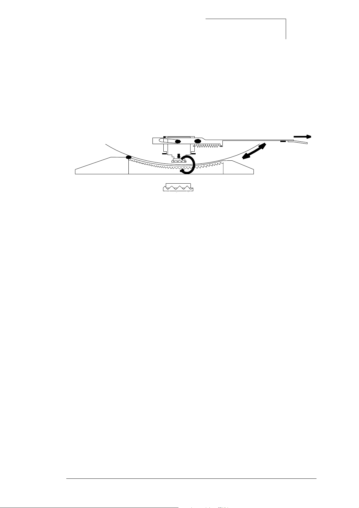
2.4.1 Tilt mechanism for resting surface
The bottom section of the resting-surface tilt mechanism is connected to the base
plate by means of 4 hexagon socket-head bolts. The resting surface is positioned in
this section and is supported on one side by rollers and on the other by teflon strips as
anti-friction bearings. The resting surface is fixed by means of gear teeth in the bottom section and the mechanical-system latch of the resting-surface tilt mechanism.
A
B
C
E
F
G
D
Fig. 1: Tilt mechanism for resting surface
Pulling the lever A presses the latch B downwards out of the gear teeth C and the resting surface D can be swivelled +15° to -20° out of the basic position. The lever is
pulled back again in each case by 2 springs and the resting surface thus fixed in position.
2.4.2 Pneumatic system (extraction)
Two extractors are provided for the Babytherm 8000:
− Extractor -0.9 bar 2M 85 040
− Extractor -0.5 bar 2M 85 045
The infinite vacuum is generated by an ejector. The extractor is supplied by way of
the O2 or compressed-air system. All plastic parts subject to contamination can be
sterilised in an autoclave at temperatures up to 134 °C.
Schutzvermerk DIN 34 beachten. Copyright reserved.
F6132200T01.fm 09.03.01
6132.200 Babytherm 8000 Version 2.0 Function description Page 6 of
28
Page 7
Dräger Medizintechnik
D
3 Mattress heating
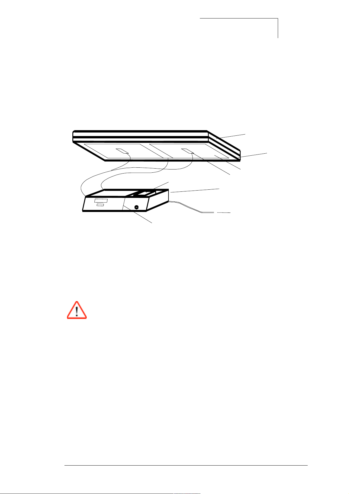
3.1 Resting-surface heating concept
The heated cot and OC versions feature a new resting-surface heater. The heating
system is made up of the following components:
HHT Gel Mattress
Aluminium plate 6mm
Heating foil
Temp. Sensors(2x2 NTCs)
Control unit
Power cord
Partition of prim./ sec. voltage
Fig. 2: Heating system
3.1.1 Mattress
The mattress consists of a thermally conductive gel (HHT = high heat transfer).
Danger:
This gel mattress is not to be used in the Babytherm 4200!
Schutzvermerk DIN 34 beachten. Copyright reserved.
F6132200T01.fm 09.03.01
6132.200 Babytherm 8000 Version 2.0 Function description Page 7 of
28
Page 8
Dräger Medizintechnik
D
3.1.2 Heating panel
The heating panel is inserted from above into the resting surface and secured with 4
screws. An all-round seal prevents the ingress of dirt and moisture. The heating
panel is made of a backing plate (6 mm aluminium) with bonded -on heating foil
24V/120W and 2 bolted-on twin temperature sensors.
3.1.3 Control unit
This unit is secured in position in the resting-surface housing with 2 slide locks.
The control unit is made up of the following components:
Connection protective
ground PCB Power + PCB Controller
V2 V11
Transformer
Connection heating
Mains input with fuses
PCB Power
R22
Horn
Relay
Connection
Sensors
Keyboard
Fuses
F2 F1
EPROM
Test points
Gold Cap
PCB Controller
4 Service-LEDs
Switch
PCB Display
Fig. 3: Control unit
− Touch-sensitive keys with LEDs
− Transformer with 4KV isolation
− Controller PCB (P 68332, EPROM, I/Os, AD conversion ...)
− Power PCB (actuation of heating, voltage regulator ...)
− Display PCB (7-segment displays with actuation, keypad interrogation)
− Accessory set for voltage version (adapter 100-127 V and other fuse links in
mains input)
Schutzvermerk DIN 34 beachten. Copyright reserved.
F6132200T01.fm 09.03.01
6132.200 Babytherm 8000 Version 2.0 Function description Page 8 of
28
Page 9
3.1.4 Block diagram of mattress heating
Main switch
120V
Voltage selection *
100V
0V
100V
24V
120V
9V
120V
0V
9V
Transformer
+5VD
100 V = Adapter YY YY YYY
230 / 240 V = no adapter necessary
110 / 127 V = Adapter XX XX XXX
* Voltage selection
0V
24V
PCB Power
Dräger Medizintechnik
D
Heater 24V/120W
Feedb. Heater
RS232
Overtemp.
+5VA
Heater Control
and monitoring
Relay on
Heater on
&
Heater
Mono
Comp.
41,6 C
+5VD
Power supply
+5VD
+9VDC
SQ
&
+5VD
Powerfail
Reset
Akku test
RQ
Q
12 bit ADC
CPU
68332
12 bit ADC
41,6 C
Horn
Gold Cap (Battery)
Horn on
1
INOP
&
Q
Mono
INOP LED
SQ
RQ
&
+5VA
Amplifier (2x)
and LED control
Powerfail monitoring
Powerfail
Powerfail
4x Service LEDs
Decoder
7-Segment-Display
Display and Key Controller
INOP
+5VD
Powerfail LED
LEDs
Keys
INOP LED
PCB Display
+9VDC
2 NTCs (2x)
PCB Controller
Keyboard
Fig. 4: Block diagram of mattress heating
Schutzvermerk DIN 34 beachten. Copyright reserved.
F6132200T01.fm 09.03.01
6132.200 Babytherm 8000 Version 2.0 Function description Page 9 of
28
Page 10

Dräger Medizintechnik
D
3.2 Functional description and software specifications
3.2.1 Front panel
The front panel contains the following components:
Touch-sensitive keys
− Range expansion
− Positive setpoint temperature and negative setpoint temperature. The setpoint
can be adjusted in 0.1 °C increments: 35.0 °C - 37.0 °C (standard range without
expansion) or 30.0 °C - 38.5 °C (with range expansion)
− 15 min. suppression for active alarms
− "Check" key for testing display elements and horn
Mains on/off switch
7-segment displays
− 3-digit display for measured value. Display range 5 °C - 45 °C.
− 3-digit display for setpoint. 35.0 °C - 37.0 °C (standard range without expansion)
or 30.0 °C - 38.5 °C (with range expansion)
LEDs
− Range expansion on (in range expansion key)
− Alarm tone suppression on (in alarm tone suppression key)
− Excess temperature
− Desired/actual-value difference 1.0 °C
− Power failure
− Heating status optional: A heating LED can be called up as decimal point by
jointly pressing for 5s the positive and negative setpoint keys in the 7-segment
display of the setpoint display. The display is generated from the heating checkback signal.
Schutzvermerk DIN 34 beachten. Copyright reserved.
F6132200T01.fm 09.03.01
6132.200 Babytherm 8000 Version 2.0 Function description Page 10 of
28
Page 11

Dräger Medizintechnik
3.2.2 Measurement of mattress temperature
The temperatures are measured at two different locations on the heating panel. The
higher temperature in each case is displayed:
T Mattress = T Display = T Meas. - T Offset
T Offset = 1.0 °C over entire measuring range
A second temperature sensor in each case at the measurement location supplies redundant measured values. A sensor warning is given in the case of a deviation of
more than 0.5 °C at a measurement point.
To avoid temperatures which could endanger patients, a processor-independent
deactivation path ensures that the maximum heating-panel temperature of 42 °C is
not exceeded.
D
3.2.3 Alarms
The mattress heating features a graded warning system. Faults detected are reported in line with their significance.
A setpoint deviation results in an intermittent alarm tone which can be acoustically
suppressed for 15 minutes by way of the "alarm suppression" key. All other faults
lead to a continuous alarm tone which cannot be suppressed. Corresponding alarm
LEDs or the measured value display flash(es) with all alarms.
Setpoint deviation alarm
− Measured value display flashes
− Appropriate alarm LED flashes
− Intermittent alarm tone (can be suppressed for 15 minutes)
The alarm tone for inadequate mattress temperature is suppressed automatically following cold start for a maximum of one hour. If the value is more than 1.0 °C below
the setpoint during this period, the alarm is displayed during the suppression period
by the corresponding LED; the measured value display does not flash and the horn is
not active.
The warning suppression time is prematurely cancelled if the measured value is not
more than 1.0 °C below the setpoint.
The LED "alarm tone suppression" lights continuously if acoustic alarms have been
suppressed.
If a further alarm situation arises during the alarm tone suppression time, the acoustic
warning is reactivated and the alarm tone suppression period cancelled.
Schutzvermerk DIN 34 beachten. Copyright reserved.
F6132200T01.fm 09.03.01
6132.200 Babytherm 8000 Version 2.0 Function description Page 11 of
28
Page 12

Dräger Medizintechnik
Excess temperature alarm 40.0 °C
− Measured value display flashes
− Appropriate alarm LED flashes
− Continuous horn tone cannot be suppressed
− Heating off
The alarm is automatically retracted if the displayed value is 0.5 °C over the setpoint.
Safety shutdown 42 °C
If a heating panel temperature of 42.0 °C is reached, the heating is automatically shut
down via a processor-independent deactivation path employing a safety relay.
− Measured value display flashes
D
− Appropriate alarm LED flashes
− INOP LED lights
− Continuous horn tone cannot be deactivated
This alarm can only be reset with the on/off switch.
Sensor alarm
Faults in the temperature sensors or in the sensing procedure in the following alarm
message:
− The three centre segments flash in the measured value display
− Continuous horn tone cannot be deactivated
− Heating off
INOP
Serious hardware or software errors, which make operation impossible for technical
or safety reasons, lead to total failure of the mattress heating. The independent shutdown path ensures that the heating is always deactivated. The following alarm message is given:
− INOP LED lights
− Continuous horn tone cannot be deactivated
− Where technically possible, the current measured value flashes on the display
The unit is inoperative.
Schutzvermerk DIN 34 beachten. Copyright reserved.
F6132200T01.fm 09.03.01
6132.200 Babytherm 8000 Version 2.0 Function description Page 12 of
28
Page 13

Dräger Medizintechnik
3.2.4 Software safety features
All errors detected in the course of the tests described below produce an INOP error
message.
RAM test
The address area of the RAM is tested in the time period between switch-on and
bootstrapping of the operating system.
EEPROM test
The EEPROM is checked following switch-on of the unit by interrogating one test cell.
The test cells are then rewritten and compared to the reference pattern again if there
is a lack of coincidence with the reference pattern. An INOP alarm is triggered if the
reference pattern can still not be read back.
D
ROM test
After switching on the unit, the ROM contents is checked by way of signature formation (CRC). ROM tests are executed cyclically during operation.
Watchdog tests
The run time of the two watchdogs is checked by way of a software counter.
Display driver test
The internal RAM of the keypad and display module 82C79 is read back immediately
after display writing and compared to the data request.
Logic monitoring of program run
The function of tasks relevant to safety are checked logically by a monitoring task.
Schutzvermerk DIN 34 beachten. Copyright reserved.
F6132200T01.fm 09.03.01
6132.200 Babytherm 8000 Version 2.0 Function description Page 13 of
28
Page 14

Dräger Medizintechnik
10-minute test
The 10-minute test is a routine in which the function of all testable hardware safety
features is checked at intervals of 10 minutes:
− Excess temperature comparator and independent shutdown path for heating
− Accuracy of mattress-temperature sensor circuit
− A/D converter and multiplexer
− Heating watchdog
− Analog +5 V voltage monitoring
Switch-on test
Switch on unit:
D
− All displays and horn are actuated for approx. 2 s
A self-test which checks the function of the processor and its peripherals is implemented during this period.
Following completion of the self-test, a setpoint of 37.0 °C is indicated with the
measured value and the label "SEt" being alternately presented on the measured
value display. The "SEt" display is a prompt for adjusting or acknowledging the setpoint.
The first ten minute test is implemented after the self-test as can be heard from the
safety relay switching.
Schutzvermerk DIN 34 beachten. Copyright reserved.
F6132200T01.fm 09.03.01
6132.200 Babytherm 8000 Version 2.0 Function description Page 14 of
28
Page 15

3.3 Mattress heating electronics
3.3.1 Design and general overview
Integration of electronics in housing
Dräger Medizintechnik
D
Fig. 5: Electronic module
The electronics module is held in place in the opening in the housing by two locks on
the side. The mains input is located on the back with the connectors for the sensors
and the heating being provided on the cover.
Schutzvermerk DIN 34 beachten. Copyright reserved.
F6132200T01.fm 09.03.01
6132.200 Babytherm 8000 Version 2.0 Function description Page 15 of
28
Page 16

Dräger Medizintechnik
D
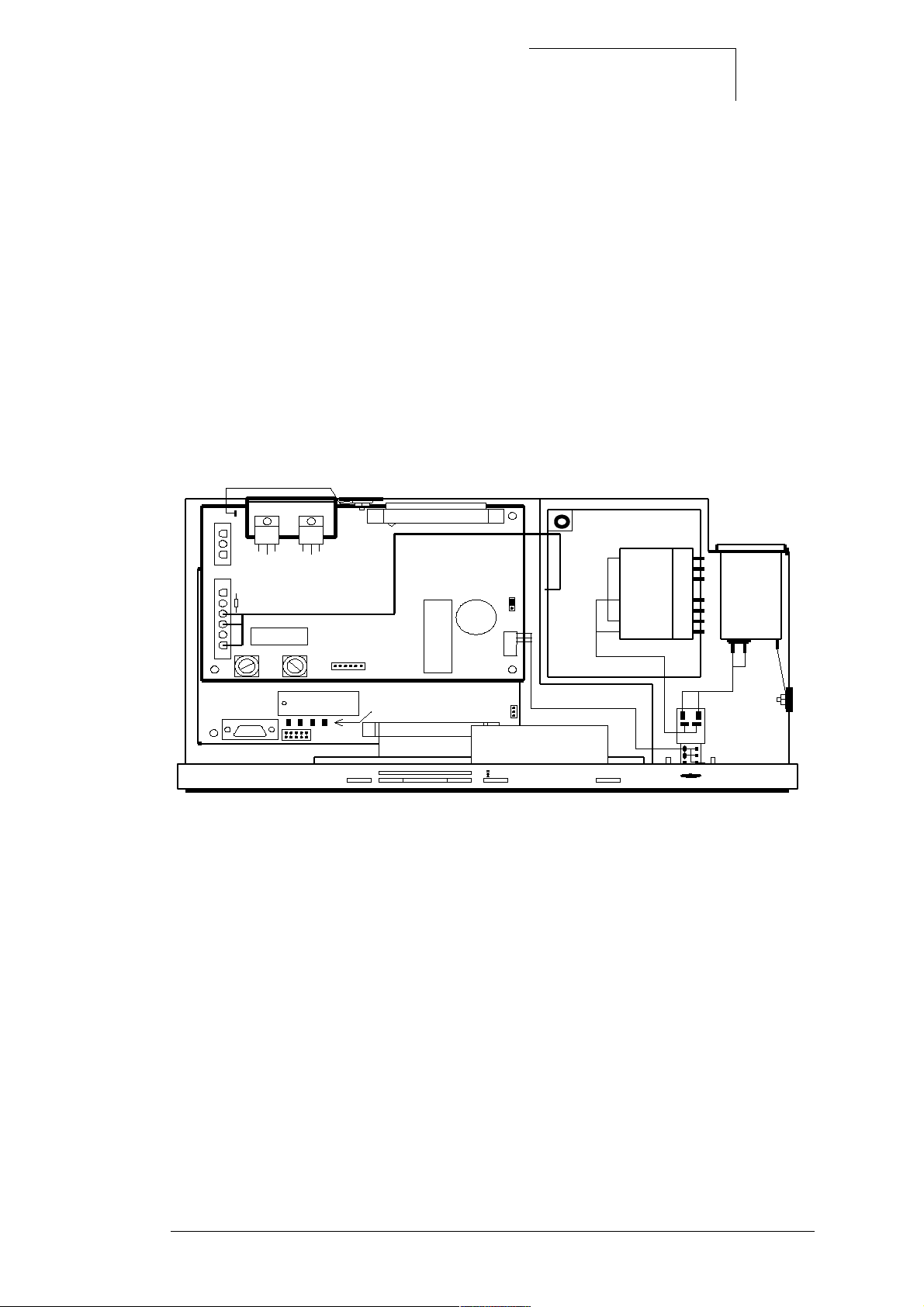
Mechanical integration of electronic components into electronics module
In the illustration below the keypad with the display PCB has been tilted forwards and
the power PCB (which is above the controller PCB in the installed condition) swivelled
out:
V2 V11
Connection
heating
R22
Relay
Fuses
F2 F1
Connection protective
conductorr PCB Power
+ PCB Controller
Connection
Sensors
Keyboard
PCB Power
Test points
PCB Controller
EPROM
RS232
Gold Cap
4 Service-LEDs
PCB Display
Horn
Mains input with fuses
Transformer
Switch
Fig. 6: Electronic components
Schutzvermerk DIN 34 beachten. Copyright reserved.
F6132200T01.fm 09.03.01
6132.200 Babytherm 8000 Version 2.0 Function description Page 16 of
28
Page 17

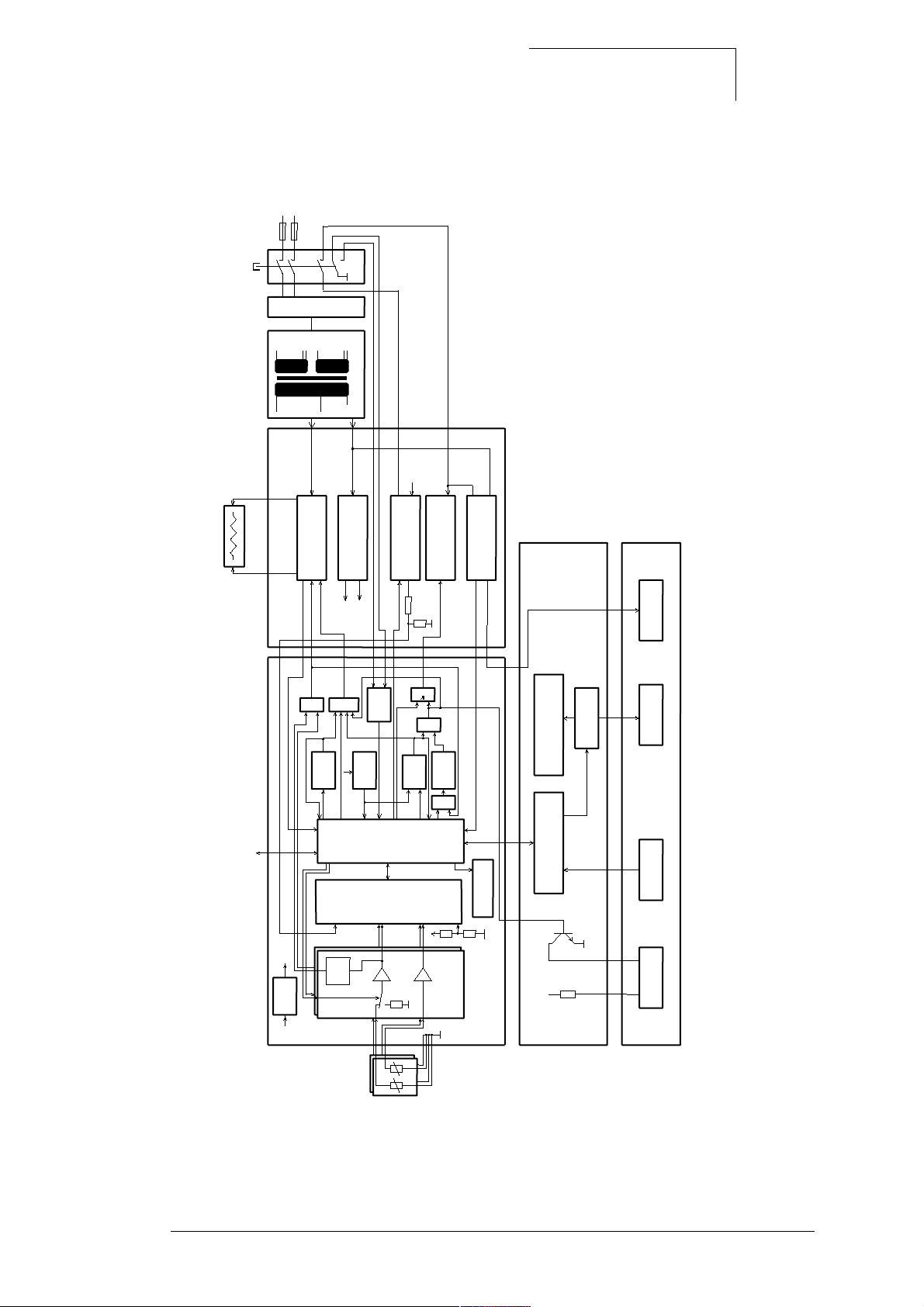
3.3.2 Block diagram of mattress heating
Main switch
120V
Voltage selection *
100V
0V
100V
120V
9V
24V
120V
0V
9V
Transformer
+5VD
230 / 240 V = no adapter necessary
* Voltage selection
0V
24V
PCB Power
Dräger Medizintechnik
100 V = Adapter YY YY YYY
110 / 127 V = Adapter XX XX XXX
D
Heater 24V/120W
Feedb. Heater
RS232
Overtemp.
+5VA
Heater Control
and monitoring
Relay on
Heater on
&
Heater
Mono
Comp.
+5VD
Power supply
+5VD
+9VDC
&
+5VD
Powerfail
Reset
41,6 C
Akku test
SQ
RQ
Q
12 bit ADC
CPU
68332
12 bit ADC
Gold Cap (Battery)
Horn on
1
&
Q
Mono
SQ
RQ
+5VA
41,6 C
Horn
INOP
INOP LED
&
Amplifier (2x)
and LED control
Powerfail monitoring
Powerfail
Powerfail
4x Service LEDs
Decoder
7-Segment-Display
Display and Key Controller
INOP
+5VD
Powerfail LED
LEDs
Keys
INOP LED
PCB Display
+9VDC
2 NTCs (2x)
PCB Controller
Keyboard
Fig. 7: Block diagram of mattress heating
Schutzvermerk DIN 34 beachten. Copyright reserved.
F6132200T01.fm 09.03.01
6132.200 Babytherm 8000 Version 2.0 Function description Page 17 of
28
Page 18

Dräger Medizintechnik
3.3.3 Power PCB
The power PCB features the following function blocks:
− Heating actuation and monitoring
− Voltage generation 5 V DC
− Actuation of horn and power failure recognition
D
Schutzvermerk DIN 34 beachten. Copyright reserved.
F6132200T01.fm 09.03.01
6132.200 Babytherm 8000 Version 2.0 Function description Page 18 of
28
Page 19

Heating actuation and monitoring
+ 5 VD
K1
Relay on
+ 5 VD
Heating on
Dräger Medizintechnik
F2
V2
24 V AC
D
Feedback
heating
Mono
Heating
24 V / 5 A
Fig. 8: Heating actuation and monitoring
− The heating runs on 24 VAC.
− The heating circuit is electrically isolated from the remainder of the electronic
system
− The heating circuit is fused (F2) on the power PCB.
− The safety relay K1 can interrupt the heating circuit in the event of a fault.
− In normal operation the heating is switched by the triac VA. An upstream zero-
voltage and phase-group switch ensures that the heating is only switched on in a
positive AC voltage pass and switched off when negative.
− The voltage drop at the heating generates pulses by way of a parallel optocoup-
ler which in turn actuate a monoflop. The output of the mono indicates the operating status of the heating.
Schutzvermerk DIN 34 beachten. Copyright reserved.
F6132200T01.fm 09.03.01
6132.200 Babytherm 8000 Version 2.0 Function description Page 19 of
28
Page 20

Voltage generation 5 V DC
F1
9 V AC
Dräger Medizintechnik
V11
+ 5 V
Regl.
D
+ 5 VD
GNDD
+ 5 V
Regl.
PCB Controller
+ 5 VA
GNDA
Fig. 9: Voltage generation 5 V DC
− The voltage supply for the 5 V is fused (F1) on the power PCB.
− The + 5 V digital supply voltage (+ 5 VD) is regulated on the power PCB.
− The + 5 V analog supply voltage (+ 5 VA) is regulated on the controller PCB.
Schutzvermerk DIN 34 beachten. Copyright reserved.
F6132200T01.fm 09.03.01
6132.200 Babytherm 8000 Version 2.0 Function description Page 20 of
28
Page 21

Dräger Medizintechnik
Actuation of horn and mains failure recognition
+ 5 VD
D
9 V AC
Batt.-Test
Test VGC
+ 5 VD
V15
VGC
Horn
V4
Gold CAP
Mono
Mains-switch auxiliary contact
Mains failure
V10
Horn
Test
mains failure
ResetQ
PCB Controller
V12 V14
V13
+ 5 VD
Fig. 10: Actuation of horn and mains failure recognition
Schutzvermerk DIN 34 beachten. Copyright reserved.
F6132200T01.fm 09.03.01
6132.200 Babytherm 8000 Version 2.0 Function description Page 21 of
28
Page 22

Dräger Medizintechnik
− The signal "mains failure" is generated if there are no rectified 9 VAC half-waves
and the monoflop is not retriggered.
− The supply for the horn and the mains failure LED is provided by a "gold cap" 3.3
F capacitor with the voltage VGC by way of the mains-switch auxiliary contact
which is made during operation.
− The voltage of the gold cap "VGC" can be measured by way of the deactivation
of the charging voltage via V15 (battery test) using a voltage divider (VGC test).
− The horn is normally switched by the processor via V12.
− In the event of mains failure, actuation of the horn and mains failure LED is by
way of the controller PCB using the signals "ResetQ" or "Mains failure test":
ResetQ ==> + 5 VD is less than 4.6 V
Mains failure test ==> Test signal from processor
Using these low-active signals the horn is actuated via V13 and V14 with the mains
failure LED being actuated via V13 and V10. The mains failure LED is located on the
keypad.
D
Schutzvermerk DIN 34 beachten. Copyright reserved.
F6132200T01.fm 09.03.01
6132.200 Babytherm 8000 Version 2.0 Function description Page 22 of
28
Page 23

Dräger Medizintechnik
3.3.4 Controller PCB
The following function blocks are located on the controller PCB:
− Processor
− Processor clock pulse generation
− RAM, EPROM
− EEPROM
− I/O lines
− LEDs
− INOP watchdogs
− Voltage monitoring
− Measured value acquisition
D
− Read-in of position of mains-switch auxiliary contacts
Processor
Use is made as Processor D1 of the MC68332 microcontroller. This controller is part
of the 683XX Motorola family. The 68332 features the following in addition to a 32-bit
CPU.
"SIM" (system integration module) with:
− Timer
− Chip-select decoder
− Bus-error decoder
− DTACK generator
2K-byte static RAM
"QSM" (Queued serial module) with:
− Asynchronous interface
− Synchronous interface
TPU (Timing processor unit), which provides time-controlled functions on 16 channels. For example pulse-duration modulation for actuation of heating.
Schutzvermerk DIN 34 beachten. Copyright reserved.
F6132200T01.fm 09.03.01
6132.200 Babytherm 8000 Version 2.0 Function description Page 23 of
28
Page 24

Dräger Medizintechnik
Processor clock pulse generation
The circuit with the quartz clock generator G1 corresponds to the recommendation
given in the Motorola user's manual. This clock pulse is multiplied in the 68332 by a
PPL up to a level of max. 16.67 MHz. The voltage supply for the internal PPL is provided by way of the PIN VDDSyn.
RAM, EPROM
The RAM (D3) and EPROM (D2) both feature 128K-bytes. The EPROM range can be
extended with 0 ohm resistors to 512K-bytes.
EEPROM
The serial EEPROM (N9) has a memory capacity of 128-words and is used to store
non-volatile data such as warm/cold-start recognition.
D
I/O lines
The following lines of the processor D1 are used as simple outputs for the Babytherm
mattress heating.
Signal name Pin Significance
ANASW1 IRQ1 Signal "analog switch 1" switches analog
channel 0 between sensor and reference
resistance 41.6 °C:
Low = Reference resistance
High = Temperature sensor, resting surface
ANASW2 IRQ2 Signal "analog switch 2" switches analog
channel 2 between sensor and reference
resistance 41.6 °C :
Low = Reference resistance
High = Temperature sensor, resting surface
HUPE1Q SIZO Actuation, horn
LED1 DSACK1Q Actuation, service LED 1
LED2 AVECQ Actuation, service LED 2
LED3 RMCQ Actuation, service LED 3
NTZAUSFTST DSQ Horn and mains failure LED test
TP2 TP2 Heating on (linked to AND gate with emer-
gency stop = excess temperature comparators and watchdog)
OUTNTZ0 IRQ5 Gold cap test
Schutzvermerk DIN 34 beachten. Copyright reserved.
F6132200T01.fm 09.03.01
6132.200 Babytherm 8000 Version 2.0 Function description Page 24 of
28
Page 25

Dräger Medizintechnik
LEDs
There are four service SMD LEDs on the controller PCB:
− Reset LED (V14):
off when processor is in "halt" or "reset" status
lights in normal operation
− LED 1 - 3 (V1, V2, V3):
Assigned by software depending on operating status.
INOP watchdogs
There are two watchdogs (D21, D22) on the controller PCB as safety features. Both
watchdogs take the form of counters which have an independent 32.678 KHz quartz
oscillator (G2) as time base.
The watchdog D21 switches off the heating if there is no retriggering. This watchdog
is tested during operation.
D
The watchdog D22 activates the INOP LED and the horn if there is no retriggering.
This watchdog is tested during operation.
Voltage monitoring
A voltage detector (V50) monitors the 5 V digital voltage. If this voltage drops below
4.6 V, the horn and INOP LED are actuated and the heating switched off independently of the processor.
Schutzvermerk DIN 34 beachten. Copyright reserved.
F6132200T01.fm 09.03.01
6132.200 Babytherm 8000 Version 2.0 Function description Page 25 of
28
Page 26

Measured value acquisition
V5
+ 5 VA
Vref
Temp.Hybrid M1
Dräger Medizintechnik
Comp.
41,6 C
UETEMP1Q
D
V8
V4
41,6 C
V9
41,6 C
+ 5 VA
V6
Temp.Hybrid M2
Temp.Hybrid M3
V7
ANASW1
Vref
Vref
ANASW2
+ 5 VA
Comp.
41,6 C
Vref
Vref
-
+
N6
UETEMP2Q
Vref
Temp.Hybrid M4
ADC
+ 5 VD + 5 VA
Test VGC
Fig. 11: Measured value acquisition
The four temperature sensors are read in on the controller PCB via four temperature
hybrids and a serial 12-bit A/D converter with integrated multiplexer.
Schutzvermerk DIN 34 beachten. Copyright reserved.
F6132200T01.fm 09.03.01
6132.200 Babytherm 8000 Version 2.0 Function description Page 26 of
28
Page 27

Dräger Medizintechnik
With two temperature channels the temperature hybrids can be switched via FETS
with the signals "ANASW1" and "ANASW2" by the NTCs to 41.6 °C resistors, so as to
be able to test the comparators with the processor-independent heating deactivation
path (excess temperature test):
ANASW1/2 = LOW ==> Reference resistance
ANASW1/2 = High ==> Measurement resistance
The outputs of the comparators are additionally read in by the processor. The temperature hybrids and the A/D converter have their own reference voltage. Furthermore,
the gold cap voltage from the power PCB and a test channel can be read in by the
A/D converter.
The +5 V analog voltage is generated on the controller PCB (refer also to block diagram in Voltage generation 5 V DC.
D
Read-in of position of mains-switch auxiliary contacts
The flip-flop D9 is used to read in the position of the mains-switch auxiliary contacts
for mains failure recognition.
3.3.5 Display PCB and keypad
The display PCB has an intelligent display and keypad controller for reading in the
keys and actuating the displays. All LEDs are located on the keypad. The LED
"INOP" is actuated by the controller PCB and the "Mains failure" LED by the power
PCB.
3.3.6 Mains switch with auxiliary contacts
The mains switch in the keypad has four switching/changeover contacts:
− 2 switching contacts for mains voltage
− 1 switching contact for mains failure alarm
− 1 changeover contact for readout of switch position for warm/cold-start recogni-
tion
Schutzvermerk DIN 34 beachten. Copyright reserved.
F6132200T01.fm 09.03.01
6132.200 Babytherm 8000 Version 2.0 Function description Page 27 of
28
Page 28

Dräger Medizintechnik
3.3.7 Transformer and mains voltage conversion
The two-chamber transformer has a minimum insulation voltage of 4 KV. By way of
an adapter the mattress heating can be switched from 230/240 V to 100 V or 120 V on
the primary side. Caution: Other mains input fuses are then required.
Note: The electrical height adjustment of Babytherm cannot be switched over.
24 V/5 A can be tapped for the heating on the secondary side. The supply voltages for
the electronics are generated by way of the 9 V centre tap.
D
4 Radiant heater 600 W
Refer to technical documentation radiant heater RH 600.
Schutzvermerk DIN 34 beachten. Copyright reserved.
F6132200T01.fm 09.03.01
6132.200 Babytherm 8000 Version 2.0 Function description Page 28 of
28
 Loading...