

Doosan D35S-5, D439E, D40S-5, D45S-5, D40SC-5 Service Manual
...
Service Manual
D439E Diesel Engine
D35S-5, D40S-5, D40SC-5, D45SC-5
D45S-5, D50C-5, D55C-5, D50SC-5, D55SC-5
D60S-5, D70S-5
D80S-5, D90S-5
SB4323E00
Nov. 2008


1
Important Safety Information
Most accidents involving product operation, maintenance and repair are caused by failure to observe basic
safety rules or precautions. An accident can often be avoided by recognizing potentially hazardous situations
before an accident occurs. A person must be alert to potential hazards. This person should also have the
necessary training, skills and tools to perform these functions properly.
Read and understand all safety precautions and warnings before operating or performing lubrication,
maintenance and repair on this product.
Basic safety precautions are listed in the “Safety” section of the Service or Technical Manual. Additional safety
precautions are listed in the “Safety” section of the owner/operation/maintenance publication.
Specific safety warnings for all these publications are provided in the description of operations where hazards
exist. WARNING labels have also been put on the product to provide instructions and to identify specific
hazards. If these hazard warnings are not heeded, bodily injury or death could occur to you or other persons.
Warnings in this publication and on the product labels are identified by the following symbol.
WARNING
Improper operation, lubrication, maintenance or repair of this product can be dangerous and could
result in injury or death.
Do not operate or perform any lubrication, maintenance or repair on this product, until you have read
and understood the operation, lubrication, maintenance and repair information.
Operations that may cause product damage are identified by NOTICE labels on the product and in this
publication.
DOOSAN cannot anticipate every possible circumstance that might involve a potential hazard. The warnings
in this publication and on the product are therefore not all inclusive. If a tool, procedure, work method or
operating technique not specifically recommended by DOOSAN is used, you must satisfy yourself that it is
safe for you and others. You should also ensure that the product will not be damaged or made unsafe by the
operation, lubrication, maintenance or repair procedures you choose.
The information, specifications, and illustrations in this publication are on the basis of information available at the
time it was written. The specifications, torques, pressures, measurements, adjustments, illustrations, and other
items can change at any time. These changes can affect the service given to the product. Obtain the complete and
most current information before starting any job. DOOSAN dealers have the most current information available.


D439E Service Manual Index 3
Index
1. General Information
General................................................................. 7
General........................................................... 7
General Precautions for Servicing ................. 11
2. Engine Mechanical System (D439E)
General............................................................... 16
Description.................................................... 16
Specification ................................................. 20
Tightening Torque......................................... 24
Special Tool.................................................. 28
Diagnosis...................................................... 30
Adjustment.................................................... 32
Timing System ................................................... 33
Timing Gear Assembly.................................. 33
Removal ....................................................... 35
Inspection ..................................................... 39
Replacement................................................. 42
Installation .................................................... 43
Cylinder head Assembly.................................... 49
Components ................................................. 49
Removal ....................................................... 51
Disassembly ................................................. 54
Inspection ..................................................... 55
Replacement................................................. 59
Reassembly.................................................. 61
Installation .................................................... 63
Crankcase .......................................................... 65
Flywheel ....................................................... 65
Removal ....................................................... 66
Inspection ..................................................... 66
Installation .................................................... 67
Cylinder Block Assembly .................................. 69
Components ................................................. 69
Removal ....................................................... 71
Disassembly ................................................. 74
Inspection ..................................................... 75
Reassembly.................................................. 81
Installation .................................................... 82
Intake and Exhaust System............................... 86
Specifications................................................ 86
Troubleshooting ............................................ 87
Turbocharger......................................................89
Components ..................................................89
Removal ........................................................91
Inspection......................................................92
Installation .....................................................93
Intake Manifold ...................................................95
Components ..................................................95
Removal ........................................................96
Installation .....................................................97
Exhaust Manifold................................................98
Components ..................................................98
Removal ........................................................99
Installation ...................................................100
Lubrication System ..........................................101
Description ..................................................101
Specification................................................105
Troubleshooting ...........................................107
Adjustment ..................................................109
Oil Pump ...........................................................111
Components ................................................111
Disassembly................................................113
Oil Cooler ..........................................................114
Components ................................................114
Disassembly................................................115
Inspection....................................................115
Reassembly.................................................116
Cooling System ................................................117
Description ..................................................117
Specification................................................118
Trouble Shooting .........................................120
Water pump ......................................................122
Components ................................................122
Removal ......................................................123
Inspection....................................................124
Installation ...................................................125

D439E Service Manual Index 4
3. Engine Electrical System (D439E)
General............................................................. 126
Specification ............................................... 126
Service Standards....................................... 128
Troubleshooting .......................................... 129
Charging System ............................................. 131
Description.................................................. 131
Adjustment.................................................. 132
Alternator ......................................................... 136
Components ............................................... 136
Disassembly ............................................... 137
Inspection ................................................... 139
Reassembly................................................ 140
Starting System ............................................... 141
Description.................................................. 141
Inspection ................................................... 142
Preheating System........................................... 144
Preheating Plug .......................................... 144
4. Fuel System
General............................................................. 145
Specification ............................................... 145
Sealant ....................................................... 146
Tightening Torque....................................... 146
Troubleshooting .......................................... 146
Engine control............................................. 148
Engine Starting System............................... 148
Fuel Tank and Fuel Line.............................. 149
Troubleshooting Procedure ......................... 150
Troubleshooting Procedure ......................... 154
Engine Control System-Electronic.................. 167
Description.................................................. 167
Engine Control Unit (ECU)............................... 170
ECU Pin Connector..................................... 170
ECU Circuit Diagram........................................ 175
Removal ..................................................... 177
Inspection ................................................... 178
Intake Air Temperature Sensor ....................... 184
Inspection ................................................... 184
Intake Air Pressure Sensor ............................. 185
Inspection ................................................... 185
Coolant Temperature Sensor...........................186
Inspection....................................................186
Installation ...................................................187
Camshaft Position Sensor ...............................188
Inspection....................................................188
Crankshaft Position Sensor.............................189
Inspection....................................................189
Rail Pressure Sensor........................................190
Inspection....................................................190
Supply Control Valve........................................191
Inspection....................................................191
Fuel Delivery System-Electronic......................192
Components ................................................192
Fuel Filter ..........................................................193
Replacement ...............................................193
Inspection....................................................193
Assembly.....................................................193
Injector..............................................................194
Components ................................................194
Cleaning ......................................................195
Removal ......................................................195
Replacement ...............................................196
Injector Replacement...................................197
ECU Replacement.......................................197
Installation ...................................................198
Common Rail Assembly...................................199
Removal ......................................................199
Installation ...................................................199
Injection Pump-Electronic................................200
Supply pump ...............................................200

D439E Service Manual Index 5
5. Service Tool
Check before use ............................................. 203
Read me first .............................................. 203
Safety Warning and Caution before Use...... 204
Hardware .......................................................... 208
Specification ............................................... 208
Introduction of Components ........................ 211
Basic Usage of G-scan .................................... 212
Power supply .............................................. 212
Power ON/OFF ........................................... 215
Description for Main Components of H/W.... 217
Description for layout of S/W screen............ 222
Connecting the DLC cable .......................... 226
Self Test Adapter ........................................ 229
Configuration ................................................... 230
Setup.......................................................... 230
User Information ......................................... 238
Version ....................................................... 241
Self Test ..................................................... 243
STEP-B Test............................................... 247
Vehicle Communication Function................... 250
Vehicle Selection ........................................ 250
Fault Code Searching ................................. 257
DTC Analysis.............................................. 260
Data Analysis.............................................. 268
Actuation Test............................................. 280
Vehicle S/W Management ........................... 282
ECU Upgrade ............................................. 286
CARB OBD-II.............................................. 299
Flight Record .............................................. 305
PC Utility .......................................................... 325
PC Utility Installation ................................... 325
How to use PC Utility .................................. 334
Appendix.......................................................... 352
Optional Item Installation and Expenditure
Exchange.................................................... 352
O/S Update................................................. 356


D439E Service Manual 1. General Information
7
1. General Information
General
General
How to Read Disassembly and Reassembly
Drawings
1. The part names and numbers in the drawings
match the ones in the text. The parts are
numbered in the order of disassembly.
2. The items to be inspected during disassembly are
shown in the disassembly drawings.
3. All torque specifications for the tightening in the
reassembly drawings may be regarded as "dry"
unless "wet" is specified.
Definition of Terminologies
Unless otherwise specified, all dimensions for the
following values in the illustration represent mm
even if the unit is not explicitly expressed.
1. Nominal Value (Abbr.: NV)
It shows dimension of an individual part, relative
clearance between parts of standard performance.
This value, however, does not necessarily
coincide with design value as it is rounded off to
fall within limits necessary for inspection.
2. Repair Limit (Abbr.: RL)
It shows the specified value, in which repair is
needed. Repair means adjustment, grinding or
replacement such as bushings, metals and others,
selection of oversize, selection of shim thickness,
etc.
3. Service Limit (Abbr.: SL)
It shows the specified value, in which parts
replacement with new ones is needed.
4. Basic Diameter (Abbr.: BD)
It shows nominal diameter of part to be measured.
5. Tightening Torque (Abbr.: T)
It shows tightening torque of bolts or nuts.
Unit
The SI unit is used. Metric notation is also presented
in parentheses.
Note, Warning and Caution
NOTE : This refers to a piece of useful information
to the customers.
CAUTION
This refers to Information about activities that
may cause damage to the vehicle.
WARNING
This refers to Information about activities that
may cause injury or damage to the driver,
passengers or other personnel.

D439E Service Manual 1. General Information
8
Conversion Table for Foot-Pound Units Into is units
Unit Unit symbol of foot-pound unit Conversion rate
Weight
kg
g
lbs
oz
1 kg = 2.2046 lbs
1 g = 0.035274 oz
Length
m
mm
ft.
in.
1 mm = 3.2808 ft.
1 mm = 0.03937 in
Volume
lit.
cc
gal.
oz
1 lit. = 0.2642 gal. (U.S.)
0.220 gal. (lmp.)
1 cc = 0.033814 oz
(U.S.)
0.035195 oz (lmp.).
Force N (Newton) lbf 1 N = 0.2248 lbf
Pressure kPa (kilopascal) lbf/in.²
1 kPa = 0.145 lbf/in.²
1 kPa = 0.2953 in.Hg
Stress N/cm² lbf/in.² 1 N/cm²= 1.45 lbf/in.²
Moment of force Nm lbf.ft 1 Nm = 0.7375 lbf.ft
Output kW (kilowatt) HP 1 kW = 1.34 HP
Temperature C F T C = (1.8 t C + 32) F
D439E Service Manual 1. General Information
9
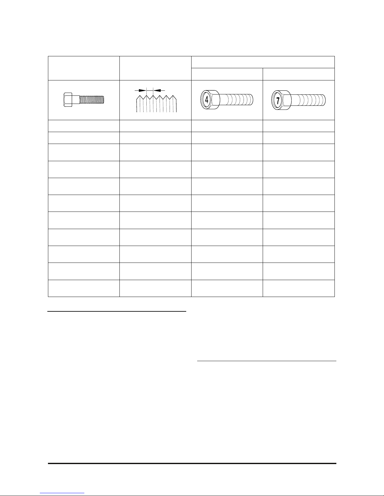
Tightening Torque Table of Standard Parts
Torque Nm (kg.cm, lb.ft)
Bolt nominal diameter Pitch (mm)
Head Mark 4 Head Mark 7
M5 0.8 3~4 (30~40, 2.2~2.9) 5~6 (50~60, 3.6~4.3)
M6 1.0 5~6 (50~60, 3.6~4.3) 9~11 (90~110, 6.5~8.0)
M8 1.25 12~15 (120~150, 9~11)
20~25 (200~250,
14.5~18.0)
M10 1.25
25~30 (250~300,
18~22)
30~50 (300~500,
22~36)
M12 1.25
35~45 (350~450,
25~33)
60~80 (600~800,
43~58)
M14
1.5
75~85 (750~850,
54~61)
120~140 (1,200~1,400,
85~100)
M16 1.5
110~130 (1,100~1,300,
54~61)
180~210(1,800~2,100,
130~150)
M18 1.5
160~180 (1,600~1,800,
116~130)
260~300(2,600~3,000,
190~215)
M20 1.5
220~250 (2,200~2,500,
160~180)
360~420 (3,600~4,200,
260~300)
M22 1.5
290~330 (2,900~3,300,
210~240)
480~550(4,800~5,500,
350~400)
M24 1.5
360~420 (3,600~4,200,
260~300)
610~700 (6,100~7,000,
NOTE
1. The torques shown in the table are standard
values under the following conditions :
• Nuts and bolts are made of galvanized steel bar.
• Galvanized plain steel washers are inserted.
• All nuts, bolts and plain washers are dry.
2. The torques in the table are not applicable under
following conditions:
• When spring washers, toothed washers and
other similar parts are inserted.
• If plastic parts are fastened.
• If self-tapping screws or self-locking nuts are
used.
• If threads and surfaces are coated with oil.
3. If you reduce the torques in the table to the
percentage indicated below-under the following
conditions, it will be the standard value.
• If spring washers are used : 85%
• If threads and bearing surfaces are stained
with oil : 85%

D439E Service Manual 1. General Information
10
Engine Identification Number Example :
1) D : DIESEL ENGINE
G : GASOLINE ENGINE
C : CNG ENGINE
2) 4 : 4 CYCLE 4 CYLINDER
6 : 4 CYCLE 6 CYLINDER
8 : 4 CYCLE 8 CYLINDER
3) Engine development order
4) Engine version
5) Model year
X : 1999 Y : 2000 1 : 2001 2 : 2002 3 : 2003
4 : 2004 5 : 2005 6 : 2006 7 : 2007 8 : 2008
6) Product serial number.
000001 ~ 999999
D439E Service Manual 1. General Information
11
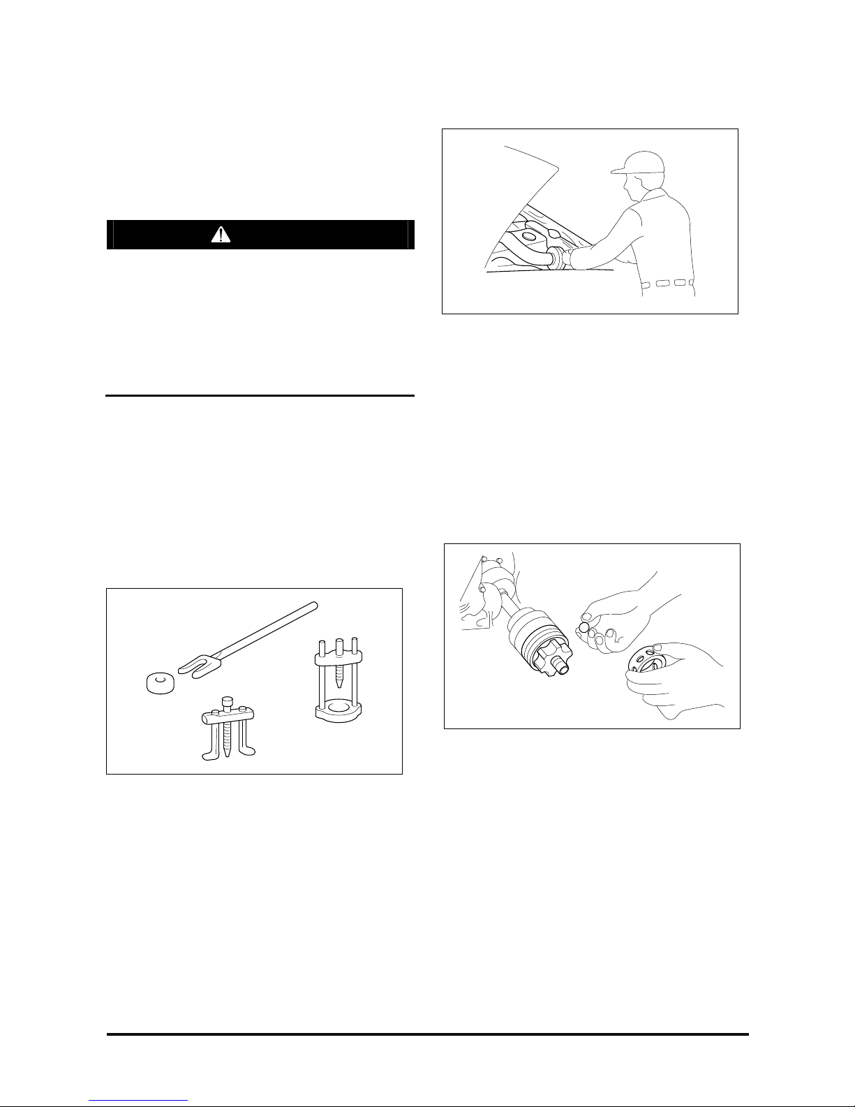
General Precautions for Servicing
Protection of the vehicle
Always make sure to cover fenders, seats, and floor
areas before commencing service works.
CAUTION
The support rod must be inserted into the hole
near the edge of the hood whenever you inspect
the engine compartment to prevent the hood
from falling and possible resulting injury.
Make sure that the support rod has been
released before closing the hood. Always check
to make sure the hood is firmly latched before
driving the vehicle.
Preparation of Tools and Measuring Equipment
Be sure that all necessary tools and measuring
equipment are available before starting work.
Special Tools
Use special tools when they are required.
Removal of Parts
First find the cause of the problem and then
determine to remove or disassemble before starting
the servicing works.
Disassembly
If the disassembly procedure is complex, requiring
many parts to be disassembled, all parts should be
disassembled in a right way so that the performance
or external appearances are not affected.
1. Inspection of parts
Each part, when removed, should be carefully
inspected for malfunction, deformation, damage,
or any other problems.
D439E Service Manual 1. General Information
12
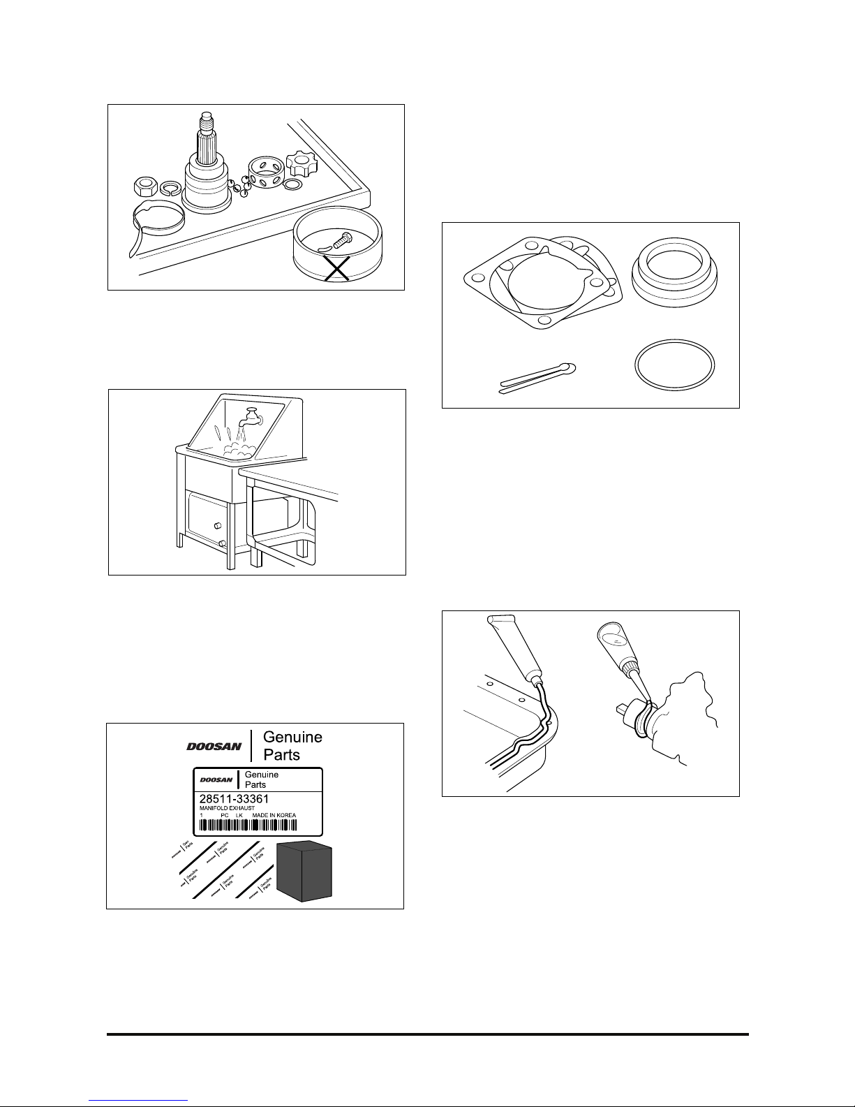
2. Arrangement of parts
All parts disassembled should be arranged
deliberately for the purpose of effective
reassembly.
3. Cleaning parts for reuse
Be sure to separate the parts to be reused for
easy indetification.
Parts
When replacing parts, be sure to use Doosan
genuine parts.
Replacement
Standard values such as torques and adjustments
must be strictly observed in the all parts reassembly.
If removed, some of the following parts must be
replaced with new ones depending on their installing
positions.
1. Oil seals
2. Gaskets
3. O-rings
4. Lock washers
5. Cotter pins (split pins)
6. Plastic nuts
7. Sealant should be applied to gaskets.
8. Oil should be applied to the moving components
of parts.
9. Specified oil or grease should be applied to the
prescribed locations (oil seals, etc.) before
assembly.
D439E Service Manual 1. General Information
13
Adjustment
Use gauges and testers to adjust the parts correctly
to the specification.
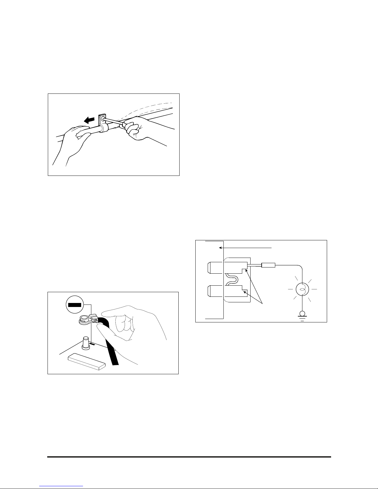
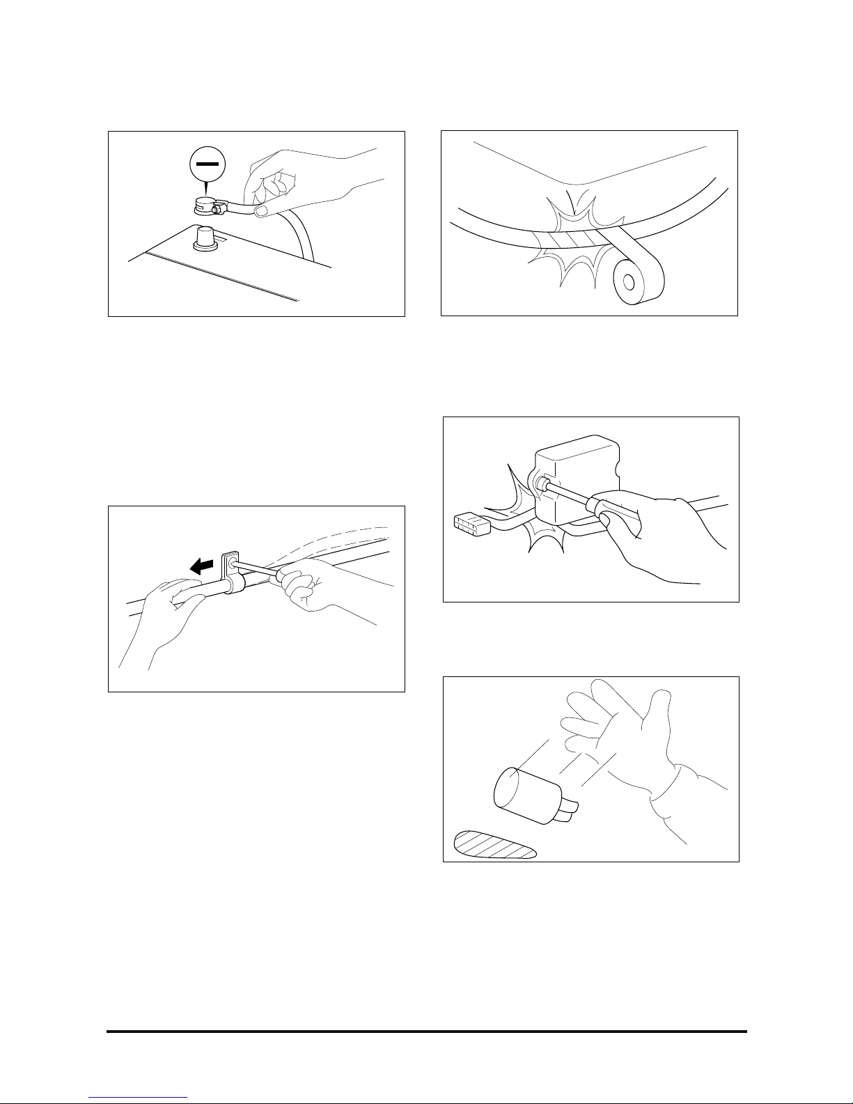
Electrical System
1. Be sure to disconnect the battery cable from the
negative (-) terminal of the battery.
2. Never pull on the wires when disconnecting
connectors.
3. Connectors will sound click when the connector is
securely locked.
4. Carefully handle sensors and relays. Be careful
not to drop them or touch other parts.
Checking Cables and Wires
1. Check to see if the terminal is tightened correctly.
2. Check to see if terminals and wires are corroded
by battery electrolyte, etc.
3. Check terminals and wires for any short circuits.
4. Check wire insulation and coating for any damage,
cracks or degrading.
5. Check to see if the conductive parts of terminals
contact other metallic parts (vehicle body and
other parts).
6. Check the grounding of parts to ensure the
complete continuity between their installing bolt(s)
and the vehicle’s body.
7. Check to see if the wiring is correct.
8. Check to see if the wiring is clamped to prevent
contact with sharp corners of the vehicle body or
heat exposed parts (exhaust manifold, etc.)
9. Check to see if the wiring is clamped firmly to
provide enough clearance to the fan from pulley,
fan belt and other revolving or moving parts.
10. Check to see if the wiring has some space so
that it can vibrate between fixed and moving
parts such as the vehicle body and the engine.
Checking Fuses
A blade type fuse test leads are provided to allow
fuse check without removing it from the fuse box.
The fuse is good if the test lamp lights up when one
lead is connected to the test leads (one at a time)
and the other lead is grounded. (Turn on the ignition
switch so that the fuse circuit becomes operative)
Fuse box
Test leads
D439E Service Manual 1. General Information
14
Servicing the Electrical System
1. Prior to servicing the electrical system, be sure to
turn off the ignition switch and disconnect the
battery ground cable.
NOTE : When performing MFI or ELC system
diagnosis, if the battery cable is removed, then, any
diagnostic trouble code retained by the computer will
be cleared. There fore, if necessary, read the
diagnostic trouble code before removing the battery
cable.
2. Secure the wiring harnesses with clamps so that
there is no slack. However, allow some slack or
distance for the wiring harness from vibrating
parts, which crosses the engine or other vibrating
parts of the vehicle. Allow wiring harness some
slack or distance so that it does not contact with
any of the adjacent parts, and then, secure the
harness by using a clamp.
3. If any section of a wiring harness interferes with
the edge of parts, or corners, wrap the section of
the harness with tape or something similar in
order to protect if from damage.
4. When installing any parts, be careful not to pinch
or damage any of the wiring harness.
5. Never throw relays, sensors or electrical parts, or
expose them to strong shock.
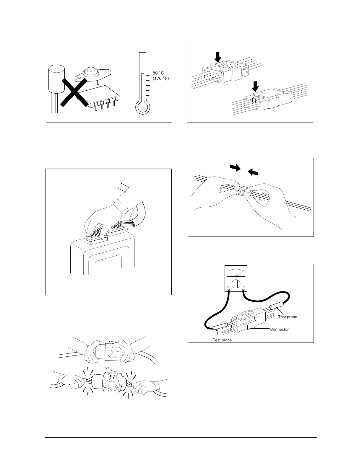
D439E Service Manual 1. General Information
15
6. The electronic parts used in the computer, relays,
etc. are subject to thermal damage easily. If any
service work is needed that may cause the
temperature to exceed 80 C (176 F), remove the
electronic parts beforehand.
7. Loose connectors may cause problems. Make
sure that the connectors are always securely
fastened.
8. When disconnecting a connector, be sure to grip
only the connector, not the wires.
9. Disconnect the connectors by pressing the
catches in the arrow direction as shown in the
illustration.
10. Connect connectors by inserting the catches,
until they make a clicking sound.
11. When using a circuit tester to check continuity or
voltage on connector terminals, insert the test
probe into the harness side. If the connector is a
sealed connector, insert the test probe through
the hole in the rubber cap until contacts the
terminal, taking care not to damage the
insulation of the wires.
D439E Service Manual 2. Engine Mechanical System (D439E)
16
2. Engine Mechanical
System (D439E)
General
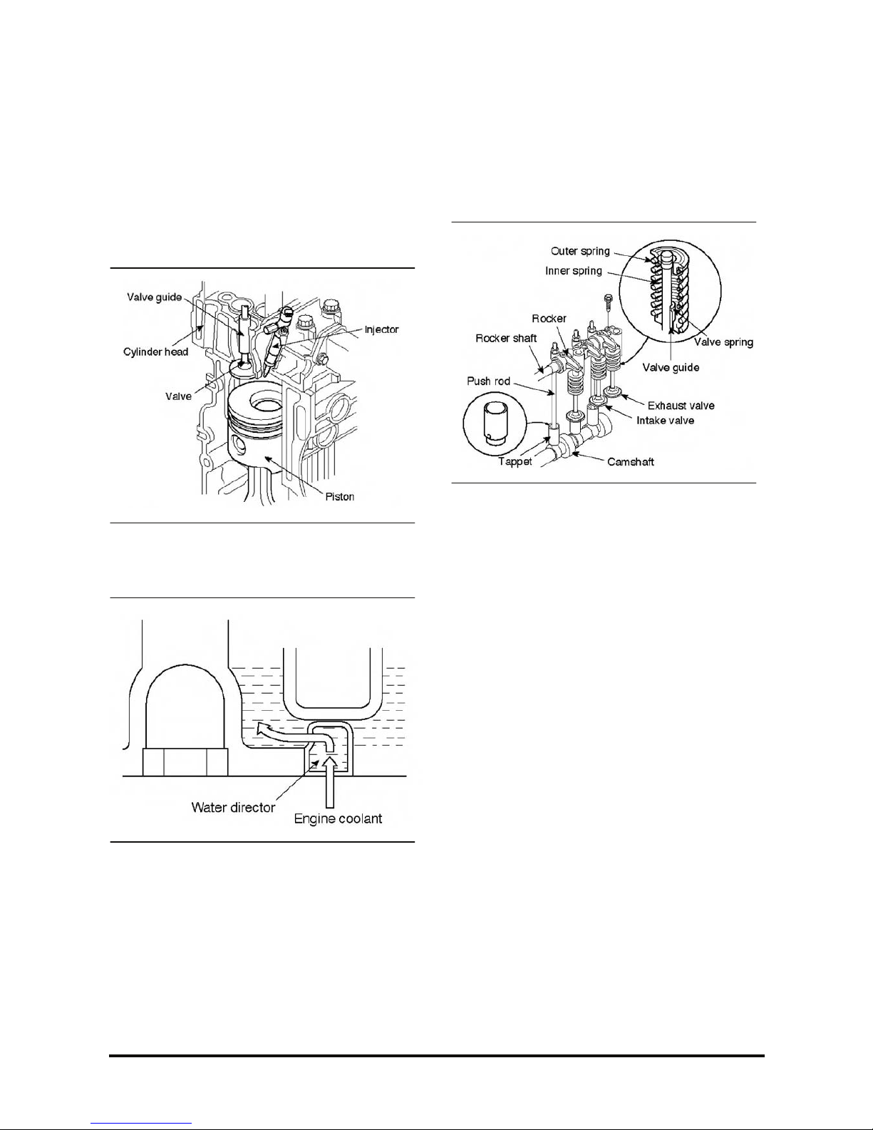
Description
Combustion
1. Combustion chamber consists of cylinder head,
piston Injector installed to the cylinder head and
valve.
2. Fuel is supplied to supply pump through the fuel
filter installed to the frame. Fuel is also supplied to
injectors throuqh injection pipe No. 1,2,3 and 4 in
common rail assembly.
3. Combustion is accomplished when fuel is Injected
directly Into combustion chamber, at that time
explosion pressure applies to the piston directly.
4. For better I efficient cooling of combustion
chamber, water director is press-fit under cylinder
head floor, which induces the coolant flow.
Valve Mechanism
1. Heat resistant steel with surface treatment is used
for intake and exhaust valve. The valve seat angle
is 45.
2. Valve stem seal, Installed to the stem, adjusts the
lubricant amount on the sliding surface of valve
and valve guide.
NOTE : Valve guide with carbon cutter is used for
exhaust valve.
3. Valve spring consists of two valve springs having
Irregular pitches. The coil directions of inner and
outer springs are opposite each other.
4. Rocker shaft is hollow cylindrical rod, whose each
end are sealed with sealing cap. Inner space of
the shaft is an engine oil passage.
5. Steel ball is installed to the lower end of push rod
and rocker assembly is installed to upper end.
6. Tappet has a cylindrical shape. As enlarging the
contacting surface contacted with camshaft, it
helps to prevent partial wear and to increase Its
durability.
D439E Service Manual 2. Engine Mechanical System (D439E)
17
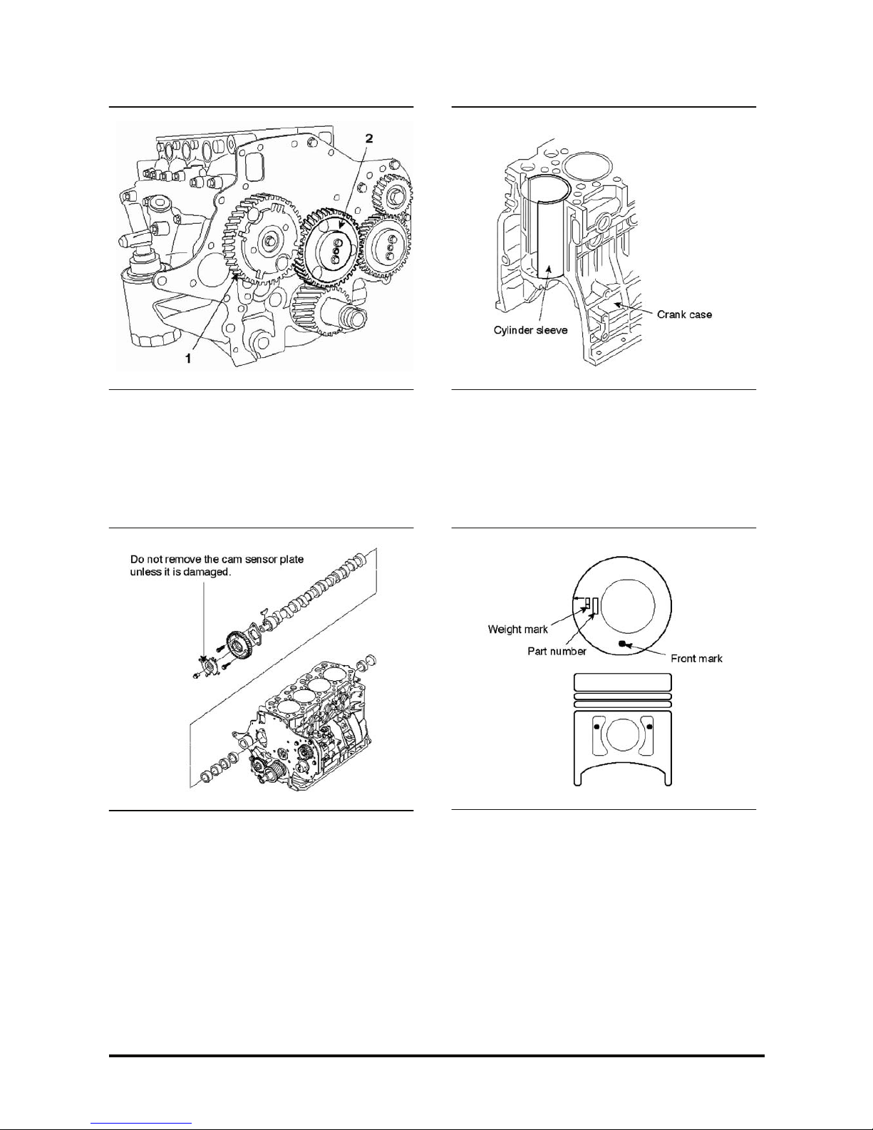
7. Camshaft assembly (1) consists of cam sensor
plate, thrust plate, cam and journal. Camshaft
gear is coupled with the idler gear A (2).
Crankcase and Cylinder Sleeve
1. Crankcase is manufactured firmly with cast iron to
prevent stress concentration and deformation.
2. The 5 camshaft bushes are installed to the
camshaft bore of the crankcase.
To facilitate the removal and installation of
camshaft, inner diameter of bush is tapered to the
rear side.
3. Cylinder sleeve made of special cast iron is
pressed fit into the crankcase.
Piston
1. Piston pin type is full float type and piston pin is
offset from thrust.
2. Marks on the piston indicate weight, part number
and oversize. The front mark indicates the front
direction of the engine.
NOTE : When assembling a piston, let the arrow
mark (→) faced to the center of cylinder head bolt
hole.
D439E Service Manual 2. Engine Mechanical System (D439E)
18
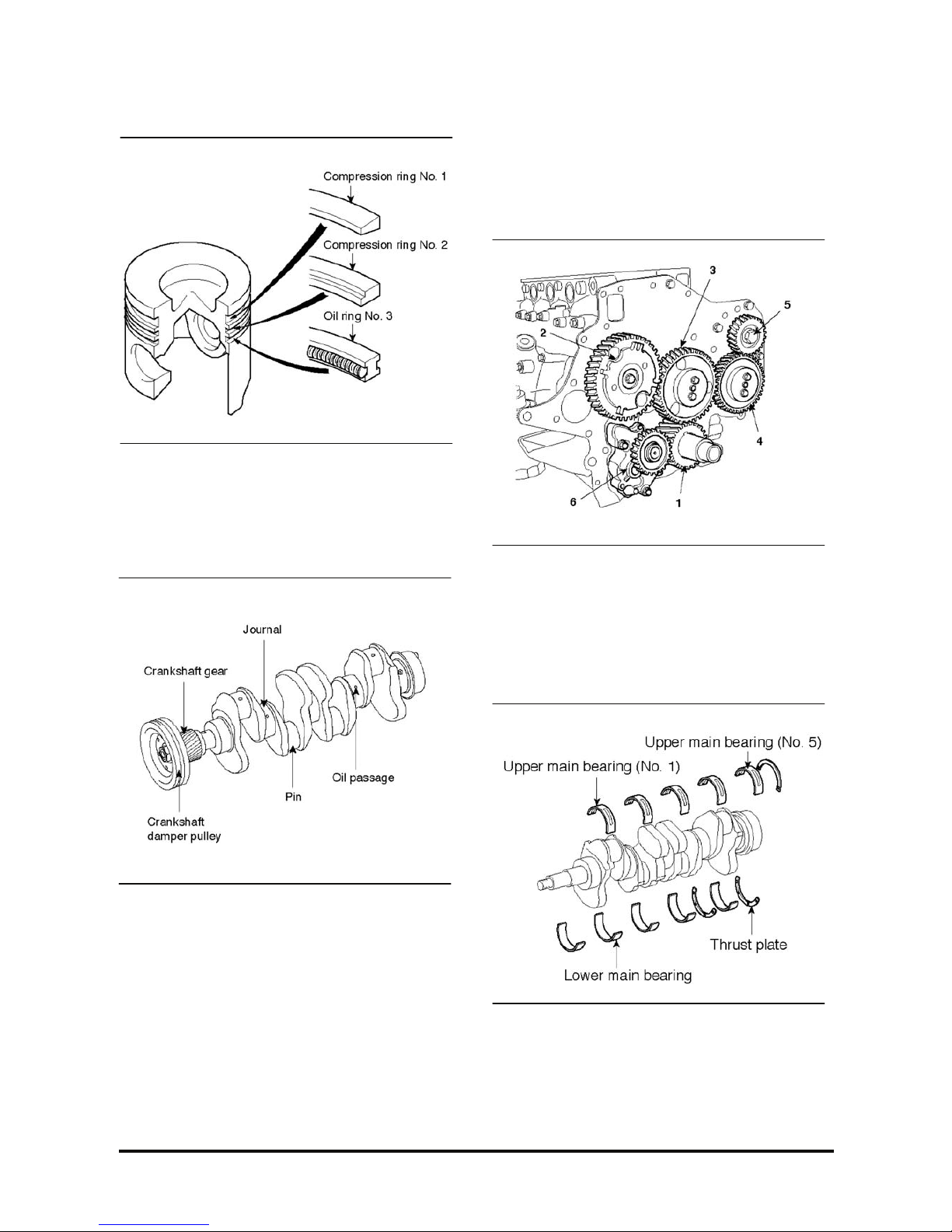
Piston Ring
Piston has two compression rings and one oil ring.
All sliding surfaces of rings are coated with
hardened chrome.
Crankshaft
1. Crankshaft is forged with high-strength alloy built
in with balance weight.
2. Pin, journal and oil seal sliding-surface are
hardened with high frequency heat treatment to
raise the resistance against frictional wear.
3. Through oil passage at the pin and journal, oil
lubricates main bearing. Oil flows to the pin for the
lubrication of connecting rod bearing.
4. Crankshaft pulley and crankshaft gear are
installed at the front end of crankshaft. The
crankshaft pulley drives alternator and water
pump using V-belt.
5. Crankshaft damper pulley absorbs the distorting
vibration of crankshaft.
6. Crankshaft gear (1) drives camshaft gear (2), idler
gear A (3), idler gear B (4), supply pump gear (5)
and oil pump gear (6).
Crankshaft Main Bearing
Upper main bearing has oil groove and oil hole
which matches with oil hole of the crankshaft.
Divided type thrust plate is Installed to the both ends
of the last bearing (N0.5).
D439E Service Manual 2. Engine Mechanical System (D439E)
19
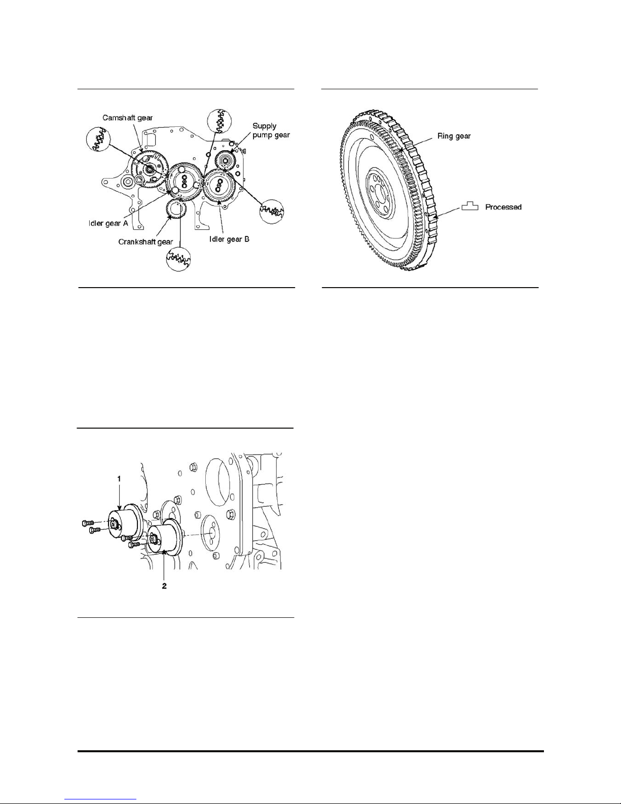
Timing Gear
1. Timing gear is installed in the timing gear case at
the front of engine.
2. Each gear is helical gear manufactured with high
precision and Its surface is treated by heat to
enhance the durability.
3. Timing marks are marked on the gear. When
assernblinq, by aligning the timing marks, gears
can be engaged correctly.
4. Bushes are press-fit into idler gear, which rotates
idler shaft A (1) and idler shaft B (2). Idler shaft
and gear oil hole provides oil passage to lubricate
bush and gear.
Flywheel
1. Flywheel is made of forged iron. Pilot bearing of
transmission drive pinion is disposed at the center
portion. Ring gear which can be geared with
starter pinion is pressed fit at the circumferential
of tile flywheel.
2. Processed is formed at the outer diameter of the
flywheel to measure the engine rpm.

D439E Service Manual 2. Engine Mechanical System (D439E)
20
Specification
Items
Standard
([] indicates standard
diameter)
Limit
Corrective
action
General lyre
Cylinder inner diameter
Cylinder stroke
Displacernent
Compression ratio
Firing order
Maximum output
Maximum torque
Compression pressure (at 200rpm)
Serial 4-cylinder 4stroke
common rail system
104mm
115mm
3,907cc
17.5 : 1
1-3-4-2
100ps/2300rpm
92ps/2300rpm
38kgf.m/1600rpm
33kgf.m/1600rpm
26kg/cm²
20kg/cm²
Adjustment
(As the
difference
between
cylinder in
within 4kg/cm²)
Valve timing
lntake valve open (BTDC)
lntake valve close (ABDC)
Exhaust valve open (BBDC)
Exhaust valve close (ATDC)
19
53
60
16
Valve
Intake valve length
Exhaust valve length
Outer diameter of Intake valve stern
Outer diameter of exhaust valve stem
Valve face angle
Thickness (rnargin) of Intake/exhaust valve
head Valve clearance (when engine is cold)
137mm
137mm
8.960~8.975mm
8.925~8.940mm
45
1.5mm
0.4mm
8.85mm
8.85mm
1.2mm
Gap between valve stem and valve guide
Intake
Exhaust
[9] 0.04~0.06mm
[9] 0.07~0.10mm
0.15mm
0.2mm
Replace
Valve guide length
lntake
Exhaust
64mm
71.5mm
Valve sinkage
Intake
Exhaust
0.75~1.25mm
0.75~1.25mm
1.5mm
1.5mm
Valve seat
Replace insert
Push rod run out - 0.4mm Replace
Valve seat width
Intake
Exhaust
2.6~3.0mm
1.8~2.2mm
3.6mm
2.8mm
Replace

D439E Service Manual 2. Engine Mechanical System (D439E)
21
Items
Standard
([] indicates standard
diameter)
Limit
Corrective
action
Outer side valve Spring
Free height
Load installed
Winding direction
Out of squareness
Inner side valve spring
Free lenqth
Load Installed
Winding direction
Out of squareness
66.1mm
26.5~29.3kg
To the right
1.5mm
60.0mm
11.5~12.7kg
Left side
1.5mm
63mm
23.7kg
2.1mm
57mm
10.3kg
2.1mm
Replace
Cylinder block
Cylinder bore
Torsion of upper crankcase
Flatness of qasket surface
Out of squareness of gasket surface
Clearance between tappet and crankcase
tappet hole
104.00~104.03mm
Below 0.07mm
0.07mm
0.05mm
[28] 0.045~0.096mm
0.2mm
0.2mm
Replace
Clearance between piston ring and piston
ring groove
No. 1 ring
No. 2 rlng
Oil ring
0.106~0.170mm
0.07~0.11mm
0.03~0.07mm
0.2mm
0.15mm
0.15mm
Replace the
piston ring
Piston ring end gap
No.1 ring
No.2 ring
Oil ring
0.25~0.40mm
0.50~0.65mm
0.20~0.40mm
1.0mm
1.5mm
1.0mm
Replace
Average protrusion of piston
Gasket qrade A.
Gasket grade B
Gasket grade C
0.466~0.526mm
0.526~0.588mm
0.588~0.648mm
Measure the
average
protrusion and
replace the
gasket with the
corresponding
grade gasket
Piston
Piston outer diameter
Clearance between piston and cylinder
sleeve
103.91~103.92mm
0.080~0.130mm
Repair with
oversize or
replace
Piston pin
Outer diameter of piston pin
Clearance between piston pin and piston pin
hole
Clearance between piston pin and
connecting rod end bush
37.994~38.00mm
0.007~0.021mm
[38] 0.025~0.046mm
0.05mm
0.1mm
Replace
Replace bush

D439E Service Manual 2. Engine Mechanical System (D439E)
22
Items
Standard
([] indicates standard
diameter)
Limit
Corrective
action
Cylinder sleeve
lnner diameter
Out of roundness
Out of cylinderness
104.00~104.03mm
0.005mm
0.015mm
100.25mm
Below
0.01mm
Below
0.03mm
Repair with
oversize or
replace
Cylinder head
Flatness of cylinder head bottom
Length from cylinder head top to bottom
Below 0.1mm
94.9~95.1mm
0.2mm
94.6mm
Repair or
replace
Connecting rod
Connecting rod twist and distortion
Oil clearance
Connecting rod bearing
Free length of connecting rod bearing
Bearing crush (measured load 600kg)
Connecting rod endplay
-
0.04~0.099mm
-
34.53~34.57mm
0.15~0.45mm
0.05mm
0.2mm
Min.
69.5mm
-
0.6mm
Repair or
replace
Camshaft
Intake cam max. length
Intake cam min. length
Intake cam lilt
Exhaust cam max. length
Exhaust cam min. length
Exhaust cam lift
Camshaft endplay
Clearance between camshaft journal and
bushing
47.105mm
39.910mm
7.195mm
46.979mm
39.658mm
7.321mm
0.05~0.22mm
Stamp mark #1,2,3,4
([54.5] 0.04~0.09mm)
Stamp mark #5
([53] 0.04~0.09mm)
0.3mm
0.15mm
Replace thrust
plate
Crankshaft
Out of roundness of pin and Journal
Out of cylindricity of pin and Journal
Crankshaft distortion
(measured at journal f\~o 1 and No 5)
Crankshaft endplay
Below 0.01mm
Below 0.006mm
Below 0.02mm
0.10~0.26mm
0.03mm
0.03mm
0.05mm
0.4mm
Replace thrust
Plate
Crankshaft main bearing
Oil clearance (#1, 2, 4, 5)
Oil clearance (#3)
Free length
Bearing crush (measured load 500kgf)
0.036~0.098mm
0.056~0.118mm
-
41.061~41.101mm
0.15mm
0.15mm
Min69.5mm
Replace

D439E Service Manual 2. Engine Mechanical System (D439E)
23
Items
Standard
([] indicates standard
diameter)
Limit
Corrective
action
Timing gear backlash
Crankshaft gear and idler gear A
Idler gear A and cam shaft gear
Idler gear A and idler gear B
Idler gear B and supply pump gear
Camshaft gear and power steering pump
gear Crankshaft gear and oil pump gear
Power steering pump gear and vacuum
pump gear
0.062~0.159mm
0.068~0.175mm
0.062~0.160mm
0.073~0.169mm
0.075~0.160mm
0.049~0.169mm
0.075~0.160mm
Repair or
replace
Idler gear endplay 0.05~0.22mm 0.3mm
Replace thrust
plate
Clearance between idler businq and idler
shaft
[45] 0.025~0.06mm 0.1mm Replace busing
Flywheel
Distortion of frictional surface
Height of frictional surface
Run-out of frictional surface (while
installed)
Below 0.05mm
24.5mm
Below 0.1mm
0.2mm
23.5mm
0.2mm
Repair or
replace

D439E Service Manual 2. Engine Mechanical System (D439E)
24
Tightening Torque
Items (diameter x length)
Screw size
O.D x
pitch(mm)
Nm Kgf.m lb•ft
Main bearing cap bolt M14x2.0 49+90° 5.0+90° 36.4+90°
Front plate flange bolt(8 x16) - 18.6~27.4 1.9~2.8 13.8~20.4
Rear oil seal slinger flange bolt(6
X12)
- 7.8~11.8 0.8~1.2 5.8~8.7
Supply pump side timing gear case
mounting bolt
- 18.6~27.4 1.9~2.8 13.8~20.4
Supply pump flange bolt - 16.7~25.5 1.7~2.6 12.4~18.9
Oil jet check valve M12X1.25 29.4 3.0 21.8
Rear plate flange bolt(10 X22) M10X1.5 63.7 6.5 47.3
Rear stiffener bracket flange bolt(8
X55)
- 18.6~27.4 1.9~2.8 13.8~20.4
Rear stiffener bracket flange bolt
(10X90)
- 38.2~58.8 3.9~6.0 28.4~43.6
Engine mounting bracket mounting
bolt
- 32.3~49 3.3~5.0 24~36.4
Cylinder
block
Crankcase oil line set screw M10X1.5 24.5 2.5 18.2
Oil strainer flange bolt(8 X16) - 18.6~27.4 1.9~2.8 13.8~20.4
Oil strainer flange bolt (8 X40) - 18.6~27.4 1.9~2.8 13.8~20.4
Oil pan mounting flange bolt (8
x12)
M8X1.2 18.6~27.4 1.9~2.8 13.8~20.4
Oil level gauge mounting flange
bolt(8 x16)
- 18.6~27.4 1.9~2.8 13.8~20.4
Oil pan drain plug M14X1.5 34.3~39.2 3.5~4.0 25.4~29.1
Oil filter element M26X1.5 19.6 2.0 14.5
Oil cooler by-pass M16X1.5 19.6 2.0 14.5
Oil cooler relief valve M16X1.5 19.6 2.0 14.5
Oil cooler drain plug M14X1.5 34.3 3.5 25.4
Oil cooler mounting flange bolt - 18.6~27.4 1.9~2.8 13.8~20.4
Oil line flange bolt - 7.8~11.8 0.8~1.2 5.8~8.7
Oil line eyebolt - 18.6~22.5 1.9~2.3 13.8~16.7
Idler gear oil supply pipe - 18.6~22.5 1.9~2.3 13.8~16.7
Turbo charger oil pipe eyebolt - 18.6~22.5 1.9~2.3 13.8~16.7
Lubrication
system
Turbo charger oil pipe flange bolt(8
x16)
- 18.6~27.4 1.9~2.8 13.8~20.4
Oil pump
Oil pump mounting flange bolt(8
X55)
- 18.6~27.4 1.9~2.8 13.8~20.4

D439E Service Manual 2. Engine Mechanical System (D439E)
25
Items (diameter x length)
Screw size
O.D x
pitch(mm)
Nm Kgf.m lb•ft
Cylinder head mounting bolt M14X2.0 147+90° 15.0+90° 109+90°
Cylinder head stud (10 X25) - 34.3 3.5 25.4
Cylinder
head
Cylinder head stud (10 X48) - 34.3 3.5 25.4
Fan clutch mounting flange bolt (8) - 21.6~32.3 2.2~3.3 16~24
Fan clutch spring washer bolt
(8x25)
- 16.7~25.5 1.7~2.6 12.4~18.9
Fan and
pulley
Fan flange nut (6) - 3.9~5.9 0.4~0.6 2.9~3.6
Thermostat cover case flange bolt - 21.6~32.3 2.2~3.3 16~24
Engine coolant temperature sensor
and gauge
- 29.4~39.2 3.0~4.0 21.8~29.1
Thermostat
housing
Thermostat case flange bolt
(10x25)
- 35.3~52.9 3.6~5.4 26.2~39.3
Timing gear case flange bolt M8X1.25 18.6~27.4 1.9~2.8 13.8~20.4
Rocker cover mounting flange bolt M8X1.25 12.7~15.7 1.3~1.6 9.5~11.6
Cam plate and thrust plate flange
bolt
- 18.6~27.4 1.9~2.8 13.8~20.4
Cam plate and oil drain plug 58.8~78.4 6.0~8.0 43.6~58.2
Camshaft gear flange bolt - 18.6~27.4 1.9~2.8 13.8~20.4
Idler gear A, B mounting bolt M8X1.25 18.6~27.4 1.9~2.8 13.8~20.4
Timing
system
Supply pump of flower valve - 7.8~12.7 0.8~1.3 5.8~9.5
Blow-by return pipe and blow-by
hose
Protect clip flange nut
- 9.8~14.7 1.0~1.5 7.3~10.9
Oil separate mounting flange bolt - 18.6~27.4 1.9~2.8 13.8~20.4
PCV blow-by return coating clip
flange bolt
- 7.8~11.8 0.8~1.2 5.8~8.7
Bleeder
system
Blow-by return pipe mounting
flange bolt
- 35.3~52.9 3.6~5.4 26.2~39.3
Alternator adjust plate mounting
bolt(10X20)
- 35.3~52.9 3.6~5.4 26.2~39.3
Alternator adjust shaft mounting
nut (10)
- 18.6~27.4 1.9~2.8 13.8~20.4
Alternator assembly mounting bolt M12X134 78.4~107.8 8.0~11 58.2~80
Vacuum pump pipe tightening bolt M6X14 3.9~5.9 0.4~0.6 2.9~3.6
Alternator
and
vacuum
pump
Vacuum pump mounting flange
bolt
M8X16 18.6~27.4 1.9~2.8 13.8~20.4

D439E Service Manual 2. Engine Mechanical System (D439E)
26
Items (diameter x length)
Screw size
O.D x
pitch(mm)
Nm Kgf.m lb•ft
Piston and
connecting
rod
Connecting rod and connecting rod
bearing cap mounting bolt
M12.5X1.25 29.4+90° 3.0+90° 21.8+90°
Flywheel mounting bolt M14X1.5 39.2+40° 4.0+40° 29.1+90°
Flywheel
and damper
pulley
Crankshaft damper pulley
mounting nut
M24X1.5 588 60 436
Mounting flange bolt (12X25) - 78.4~107.8 8.0~11.0 58.2~80
Mounting flange bolt (12X25) - 37.2~53.9 3.8~5.5 27.6~40
Starter
motor
Mounting flange bolt (12) 37.2~53.9 3.8~5.5 27.6~40
Glow plug harness flange nut - 3.9~5.9 0.4~0.6 2.9~3.6
Glow plug
Plain washer nut - 1~1.5 0.1~0.15 0.7~1.1
Actuator mounting flange bolt - 7.8~11.8 0.8~1.2 5.8~8.7
Butterfly valve shaft mounting nut
(8)
- 16.7~27.4 1.7~2.8 12.4~20.4
Intake manifold front hanger
mounting flange bolt (10x20)
- 32.3~49 3.3~5.0 24~36.4
Intake
manifold
Intake manifold mounting flange
bolt (8 X20)
- 18.6~27.4 1.9~2.8 13.8~20.4
Exhaust manifold heater protector
cover mounting bolt
M8x1.25 11.8 1.2 8.7
Exhaust
manifold
Exhaust manifold assembly self
lock
Flange nut
M10X1.25 41.2 4.2 30.5
Engine
cover
Top shield bolt screw - 7.8~11.8 0.8~1.2 5.8~8.7
Turbo charger and Intake pipe
clamp band
M9X2.5 3.9 0.4 2.9
Turbo
charger
Turbo charger oil pipe eyebolt M8X1.25 11.8 1.2 8.7
Fuel suction hose - 14.7~19.6 1.5~2.0 10.9~14.5
Common rail fuel return B
mounting screw
- 16.7~22.5 1.7~2.3 12.4~16.7
Fuel return A and fuel supply hose
protect clip flange bolt
- 9.8~19.6 1.0~2.0 7.3~14.5
Fuel return A and rear plate clamp
plate bolt
- 3.9~5.9 0.4~0.6 2.9~3.6
Injector pipe (No. 1, 2, 3, 4) - 39.2~49 4.0~5.0 29.1~36.4
Injector nozzle bridge bolt - 30.4~34.3 3.1~3.5 22.5~25.4
Common rail bracket Flange bolt - 21.6~32.3 2.2~3.3 16~24
Fuel
system
Pipe (between supply pump and
common rail)
- 39.2~49 4.0~5.0 29.1~36.4

D439E Service Manual 2. Engine Mechanical System (D439E)
27
Items (diameter x length)
Screw size
O.D x
pitch(mm)
Nm Kgf.m lb•ft
Engine speed sensor mounting
bolt
- 7.8~11.8 0.8~1.2 5.8~8.7
Cam speed sensor mounting bolt - 7.8~11.8 0.8~1.2 5.8~8.7
Sensor
Booster pressure sensor (M. A. P)
mounting bolt
- 7.8~11.8 0.8~1.2 5.8~8.7
D439E Service Manual 2. Engine Mechanical System (D439E)
28
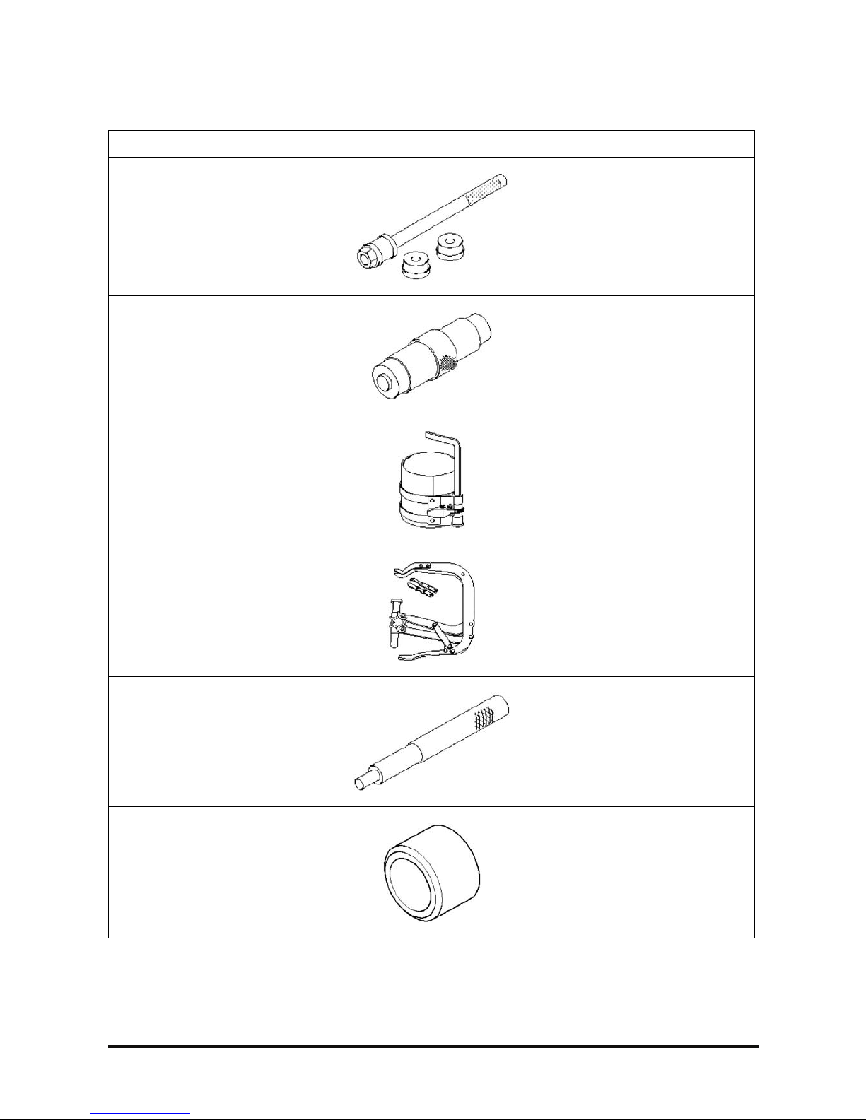
Special Tool
Tool (part no. and part name) Shape Usage
09212-41200
Camshaft bushing remover and
installer
Installation and removal of
camshaft bushing
09246-41000
Idler gear bushing puller
Installation and removal of
connecting rod bushing
09222-83200
Piston guide clamp
Installation of piston
09222-83300
Valve spring compressor
Installation and removal of valve
cotter
09221 -41100
Valve guide remover
Removal of valve guide
09221-41150
Valve guide Installer
Installation of valve guide
(Use together with 09211-41100)
 Loading...