


Operation &
Maintenance Manual
LIFT TRUCKS
D20S-3, D25S-3, D30S-3, D33S-3
G20E-3, G25E-3, G30E-3
GC20E-3, GC25E-3, GC30E-3
G20P-3, G25P-3, G30P-3, G33P-3
GC20P-3, GC25P-3, GC30P-3
D32S-3 (6,500lb@24"L.C.)
G32E-3 (6,500lb@24"L.C.)
G32P-3 (6,500lb@24"L.C.)
GC32E-3 (6,500lb@24"L.C.)
GC32P-3 (6,500lb@24"L.C.)
SB2302E06

WARNING
Do not start, operate or service this machine unless you have read and understood
these instructions and received proper training.
Unsafe or improper use of the machine may cause serious injury or death.
Operators and maintenance personnel must read this manual and receive training
before operating or maintaining the machine.
This manual should be kept with the machine for reference and periodically
reviewed by the machine operator and by all personnel who will come into contact
with it.
The following warning is provided pursuant to California Health & Safety Code Sections
25247.5 et, seq,
WARNING
California Proposition 65
Engine Exhaust, some of its constituents, and certain vehicle components contain
or emit chemicals known to the State of California to cause cancer and birth
defects or other reproductive harm.
Battery posts, terminals and related accessories contain lead and lead
compounds, chemicals known to the State of California to cause cancer and birth
defects or other reproductive harm.
WASH HANDS AFTER HANDLING.

Table of Contents
Information Section
Information Section
Foreword................................................................ 2
Literature Information............................................. 2
Safety Section
Important Safety Information ................................. 4
Safety..................................................................... 5
Warning Signs and Labels.................................. 5
Parking brake...................................................... 9
General Hazard Information ............................. 10
Operation Information....................................... 11
Maintenance Information.................................. 14
Operator Restraint System(If Equipped) ..........17
Avoiding Lift Truck Tipover ............................... 21
Safety Rules ..................................................... 23
How to Survive in a Tipover.............................. 28
General Section
Specifications....................................................... 30
Noise and Vibration ............................................. 50
Capacity Chart ..................................................... 51
Serial Number...................................................... 61
Operator's Warning and Identification Plate........ 64
Operation Section
Operator's Station and Monitoring Systems ........ 65
Lift Truck Controls................................................ 69
Refueling.............................................................. 72
Before Starting the Engine................................... 75
Starting the Engine .............................................. 78
Dual Fuel System (If G424 Dual Fuel Engine
Equipped) ............................................................ 81
Dual Fuel System (G424E Engine Only)............. 83
Lift Truck Operation ............................................. 86
G424E/G430E Electronic Controlled LP Engines
(If Equipped) ........................................................ 89
Advanced Diagnostics ....................................... 104
Table a. MI-04 Diagnostic Fault Codes (Flash
Codes) ...............................................................106
Auto Shift Controller ASC-100 (If Equipped) ..... 112
Operating Techniques........................................ 115
Parking the Lift Truck......................................... 119
Lift Fork Adjustment........................................... 120
Storage Information ........................................... 121
Transportation Hints........................................... 122
Towing Information............................................. 123
Maintenance Section
Inspection, Maintenance and Repair of Lift Truck
Forks ..................................................................124
Tire Inflation Information.....................................128
Torque Specifications .........................................129
Cooling System Specifications...........................131
Fuel Specifications .............................................133
Lubricant Information .........................................135
Lubricant Viscosities and Refill Capacities.........137
Maintenance Intervals ........................................138
When Required ..................................................142
Every 10 Service Hours or Daily ........................152
First 50 - 100 Service Hours or a Week.............157
First 250 Service Hours or a Month ...................162
Every 250 Service Hours or Monthly..................163
Every 500 Service Hours or 3 Months ...............170
Every 1000 Service Hours or 6 Months .............179
Every 1500 Service Hours or 9 Months .............185
Every 2000 Service Hours or Yearly ..................188
Every 2500 Service Hours or 15 Months ...........195
Every 3000 Service Hours or 18 Months ...........198
Every 4500 Service Hours or two Years ............199
Index Section
Index...................................................................200
-1-

Information Section
Foreword
Literature Information
This manual should be stored in the operator’s
compartment in the literature holder or seat back
literature storage area.
This manual contains safety, operation,
transportation, lubrication and maintenance
information.
Some photographs or illustrations in this publication
show details or attachments that can be different
from your lift truck. Guards and covers might have
been removed for illustrative purposes.
Continuing improvement and advancement of
product design might have caused changes to your
lift truck which are not included in this publication.
Read, study and keep this manual with the lift truck.
Whenever a question arises regarding your lift truck,
or this publication, please consult your DAEWOO
dealer for the latest available information.
Safety
The Safety Section lists basic safety precautions. In
addition, this section identifies the text and
locations of warning signs and labels used on the
lift truck.
Read and understand the basic precautions listed
in the Safety Section before operating or
performing lubrication, maintenance and repair on
this lift truck.
Operator Restraint System (If Equipped)
This manual contains safety, operation and
maintenance information for the DAEWOO operator
restraint system. Read, study and keep it handy.
WARNING
Your DAEWOO truck comes equipped with an
operator restraint system. Should it become
necessary to replace the seat for any reason, it
should only be replaced with another DAEWOO
operator restraint system.
Photographs or illustrations guide the operator
through correct procedures of checking, operation
and maintenance of the DAEWOO operator
restraint system.
SAFE and EFFICIENT OPERATION of a lift truck
depends to a great extent on the skill and alertness
on the part of the operator. To develop this skill the
operator should read and understand the Safe
Driving Practices contained in this manual.
Forklift trucks seldom tipover, but in the rare event
they do, the operator may be pinned to the ground
by the lift truck or the overhead guard. This could
result in serious injury or death.
Operator training and safety awareness is an
effective way to prevent accidents, but accidents
can still happen. The DAEWOO operator restraint
system can minimize injuries. The DAEWOO
operator restraint system keeps the operator
substantially within the confines of the operator’s
compartment and the overhead guard.
This manual contains information necessary for
Safe Operation. Before operating a lift truck, make
sure that the necessary instructions are available
and understood.
Operation
The Operation Section is a reference for the new
operator and a refresher for the experienced one.
This section includes a discussion of gauges,
switches, lift truck controls, attachment controls,
transportation and towing information.
Photographs and illustrations guide the operator
through correct procedures of checking, starting,
operating and stopping the lift truck.
Operating techniques outlined in this publication
are basic. Skill and techniques develop as the
operator gains knowledge of the lift truck and its
capabilities.
-2-

Information Section
Maintenance
The Maintenance Section is a guide to equipment
care. The illustrated, step-by-step instructions are
grouped by servicing intervals. Items without
specific intervals are listed under “When Required”
topics. Items in the “Maintenance Intervals” chart
are referenced to detailed instructions that follow.
Maintenance Intervals
Use the service hour meter to determine servicing
intervals. Calendar intervals shown (daily, weekly,
monthly, etc.) can be used instead of service hour
meter intervals if they provide more convenient
servicing schedules and approximate the indicated
service hour meter reading. Recommended service
should always be performed at the interval that
occurs first.
Under extremely severe, dusty or wet operating
conditions, more frequent lubrication than is
specified in the “Maintenance Intervals” chart might
be necessary.
Perform service on items at multiples of the original
requirement. For example, at “Every 500 Service
Hours or 3 Months”, also service those items listed
under “Every 250 Service Hours or Monthly” and
“Every 10 Service Hours or Daily”.
Environment Management
Note that DAEWOO INDUSTRIAL VEHICLE
DIVISION is ISO 14001 certified which is
harmonized with ISO 9001. Periodic
ENVIRONMENTAL AUDITS & ENVIRONMENTAL
PERFORMANCE EVALUATIONS have been made
by internal and external inspection entities.
LIFE-CYCLE ANALYSIS has also been made
through out the total product life. ENVIRONMENT
MANAGEMENT SYSTEM includes DESIGN FOR
ENVIRONMENT from the initial stage of the design.
ENVIRONMENT MANAGEMENT SYSTEM
considers environmental laws & regulations,
reduction or elimination of resource consumption as
well as environmental emission or pollution from
industrial activities, energy saving,
environment-friendly product design(lower noise,
vibration, emission, smoke, heavy metal free,
ozone depleting substance free, etc.), recycling,
material cost reduction, and even environmentally
oriented education for the employee.
-3-

Safety Section
Important Safety Information
Most accidents involving product operation, maintenance and repair are caused by failure to observe basic
safety rules or precautions. An accident can often be avoided by recognizing potentially hazardous situations
before an accident occurs. A person must be alert to potential hazards, and use common sense. Persons
must also have the necessary training, skills and tools before attempting to perform these functions.
Improper operation, lubrication, maintenance or repair of this product can be dangerous and could
result in injury or death.
Do not operate or perform any lubrication, maintenance or repair on this product, until you have read
and understood the operation, lubrication, maintenance and repair information.
Safety precautions and warnings are provided in this manual and on the product. If these hazard
warnings are not heeded, bodily injury or death could occur to you or other persons.
The hazards are identified by the “Safety Alert Symbol” and followed by a “Signal Word” such as “WARNING”
as shown below.
WARNING
The meaning of this safety alert symbol is as follows:
Attention! Become Alert! Your Safety is involved.
The message that appears under the warning, explaining the hazard, can be either written or pictorially
presented.
Operations that may cause product damage are identified by NOTICE labels on the product and in this
publication.
DAEWOO cannot anticipate every possible circumstance that might involve a potential hazard, and common
sense is always required. The warnings in this publication and on the product are therefore not all inclusive.
Before any tool, procedure, work method or operating technique not specifically recommended by DAEWOO
is used, you must be sure that it is safe for you and others. You should also ensure that the product will not be
damaged or made unsafe by the operation, lubrication, maintenance or repair procedures you choose.
The information, specifications, and illustration in this publication are on the basis of information available at
the time it was written. The specifications, torques, pressures, measurements, adjustments, illustrations, and
other items can change at any time. These changes can affect the service given to the product. Obtain the
complete and most current information before starting any job. DAEWOO dealers have the most current
information available.
-4-
Safety
The safety rules and regulations in this section are
representative of some, but not all rules and
regulations noted under the Occupational Safety
and Health Act (OSHA) and are paraphrased
without representation that the OSHA rules and
regulations have been reproduced verbatim.
Please refer to 1910. 178 in Federal Register Vol.
37, No. 202, the National Fire Protection
Association No. 505 (NFPA), American National
Standard, ANSI B56. 1 Safety Standard for Low lift
and High Lift Trucks and subsequent revisions for a
complete list of OSHA rules and regulations as to
the safe operation of powered industrial lift trucks.
Since regulations vary from country to country
outside in U.S.A., operate this lift truck in
accordance with local regulations.
DAEWOO lift trucks are manufactured according to
the regulations and standards laid down in EU
Machinery Directive 98/37/EC and EMC directive
89/336/EC. Please refer to the Directives
89/655/EC and 89/391/EC and its amendments for
the safe use of DAEWOO lift trucks.
The most effective method of preventing serious
injury or death to the lift truck operator or others is
for the lift truck operator to be familiar with the
proper operation of the lift truck, to be alert and to
avoid actions or conditions which can result in an
accident.
Do not operate a lift truck if in need of repair,
defective or in any way unsafe. Report all defects
and unsafe conditions immediately. Do not attempt
any adjustments or repairs unless trained and
authorized to do so.
Safety Section
Warning Signs and Labels
There are several specific safety signs on your lift
truck. Their exact location and description of the
hazard are reviewed in this section. Please take the
time to familiarize yourself with these safety signs.
Make sure that you can read all warning and
instruction labels. Clean or replace these labels if
you cannot read the words or see the pictures.
When cleaning the labels use a cloth, water and
soap. Do not use solvent, gasoline, etc.
You must replace a label if it is damaged, missing
or cannot be read. If a label is on a part that is
replaced, make sure a new label is installed on the
replaced part. See your dealer for new labels.
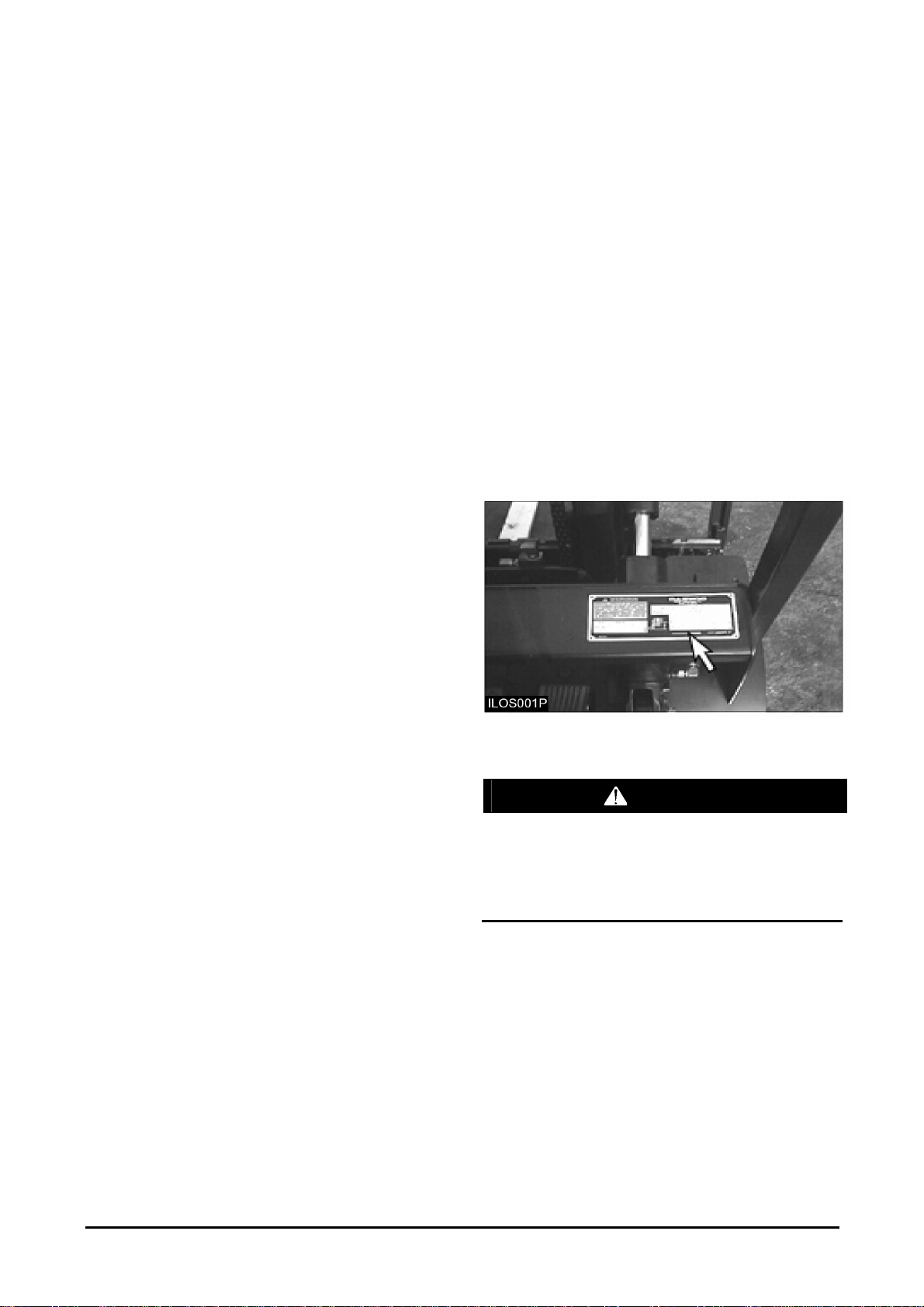
Traing Required To Operate or Service
Warning
Located on the right side of the steering wheel.
WARNING
Improper operation or maintenance could result
in injury or death. Do not operate or work on the
lift truck unless you are properly trained. Read
and understand the Operation and Maintenance
Manual. Additional manuals are available from
DAEWOO Lift Truck dealers.
This label also provides allowable lift truck capacity
information
-5-
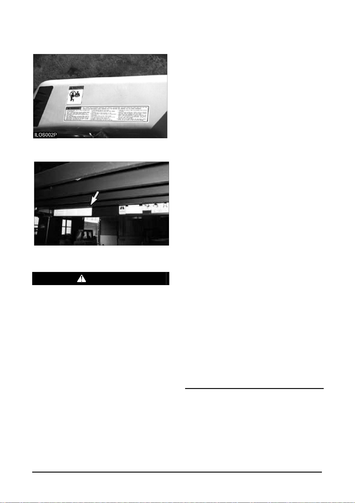
Safety Section
General Warning to Operator
Located on the right side of the operator's seat
(STD).
Located on the overhead guard (If Convenience
Package Equipped).
WARNING
Only trained and authorized personnel may
operate this machine. For safe operation, read
and follow the operation and maintenance
Manual furnished with this lift truck and
observe the following warnings:
1. Before starting machine. Check all controls and
warning devices for proper operation.
2. Refer to machine identification plate for
allowable machine capacity. Do not overload.
Operate machines equipped with attachments
as partially loaded machines when not handling
a load.
3. Put directional control or shift lever in neutral
before “ON - OFF” switch is turned on.
4. Start, turn and brake smoothly. Slow down for
turns, slippery or uneven surfaces. Extremely
poor surfaces should be repaired. Avoid running
over loose objects or holes in the roadway
surfaces. Use extreme caution when turning on
inclines.
5. Travel with load as low as possible and tilted
back. If load interferes with visibility, travel with
load trailing.
6. On grade operations travel with load up grade.
7. Watch out for pedestrians and obstructions.
Check overhead clearances.
8. Do not permit riders on forks or machine at any
time.
9. Do not allow anyone to stand or pass under the
elevated portion of any machine.
10. Be sure operating surface can safely support
machine.
11. Operate machine and attachments only from
operator's position.
12. Do not handle unstable or loosely stacked
loads.
13. Use minimum tilt when picking up or depositing
a load.
14. Use extreme care when handling long, high, or
wide loads.
15. Forks should be completely under load and
spread apart as far as load permits.
16. Machine should be equipped with overhead
guard or equivalent protection. Where load
requires it, use a load backrest extension. Use
extreme caution if operating without these
devices.
17. Parking - Lower lifting mechanism to floor. Put
directional control or shift lever in neutral. Set
parking/secondary brake. Turn “ON - OFF”
switch off. Chock wheels if machine is on incline.
Disconnect battery when storing electric
machines.
18. Observe safety rules when handling fuel for
engine powered machine and when changing
batteries for electric machines.
-6-
Safety Section
Pressure Warning
WARNING
Contents under pressure may be hot. Allow to
cool before opening.
Located on the radiator top tank by the radiator
cap.
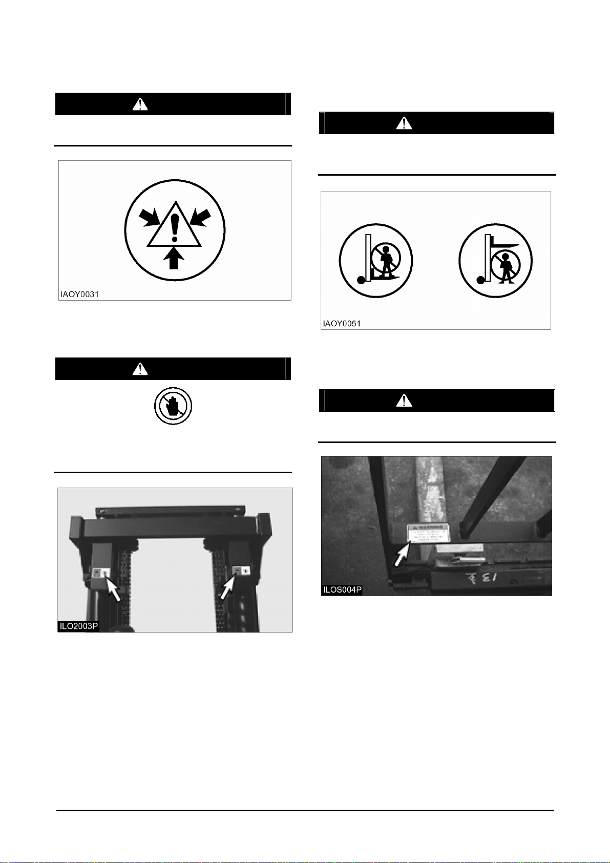
Hand Placement Warning
WARNING
No Standing On Fork Warning
No Standing Under Fork Warning
WARNING
Do not stand or ride on the forks. Do not stand
or ride on a load or pallet on the forks. Do not
stand or walk under the forks.
Located on the lift cylinder.
Load Backrest Must Be In Place
Warning
No hands. Do not place hands in this area. Do
not touch, lean on, or reach through the mast or
permit others to do so.
Located on the mast.
WARNING
Operation without this device in place may be
hazardous.
Located on the load backrest.
-7-
Safety Section
Overhead Guard Must Be In Place
Warning
WARNING
Operation without this device in place may be
hazardous. This guard conforms to
A.N.S.I.B56.1 and F.E.M.Section IV. This design
has been tested with an impact of appropriate
valve.
Located on the Overhead Guard.
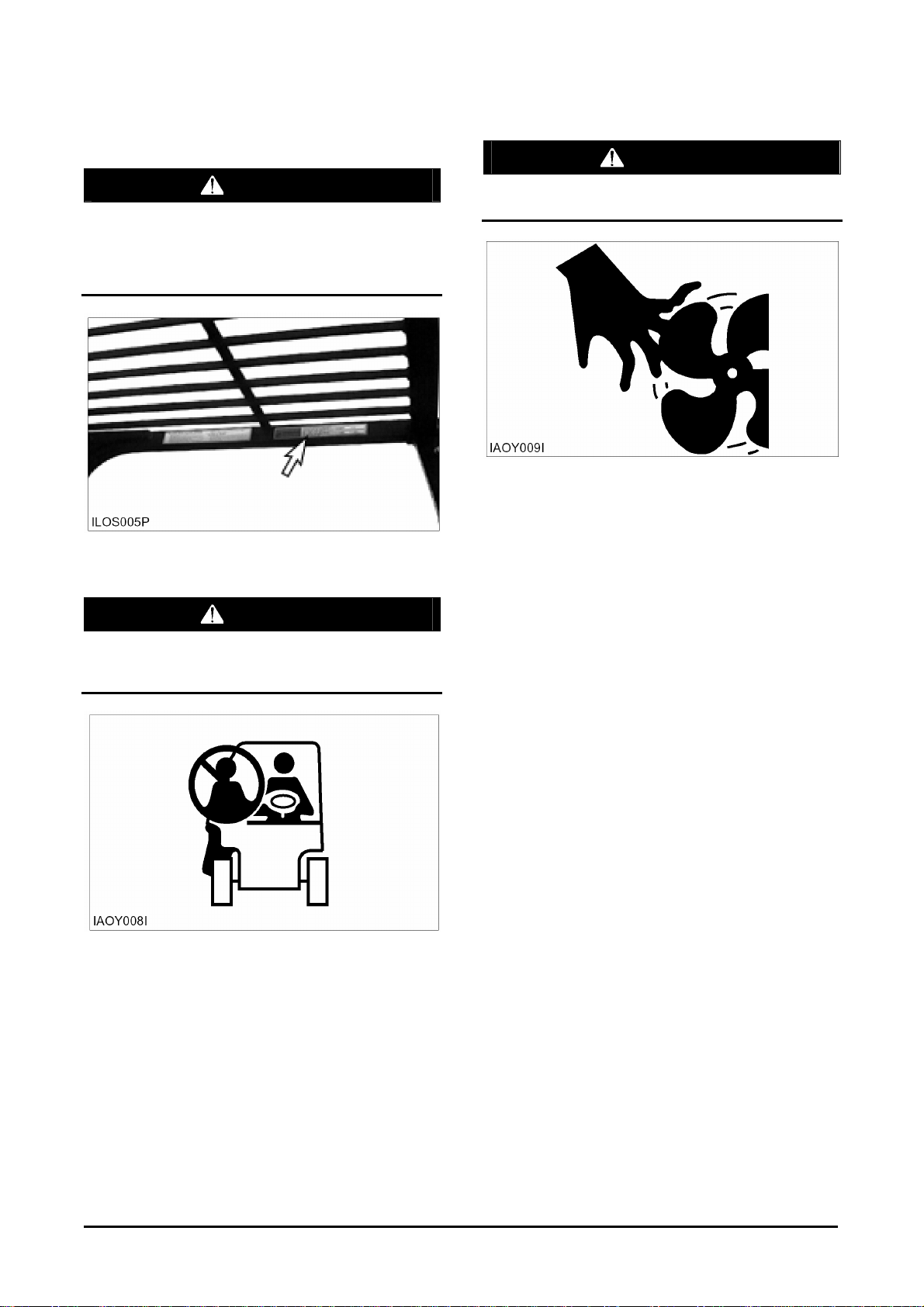
No Riders Warning
Moving Fan Warning
WARNING
To avoid personal injury, stay clear of moving
fan.
Located inside the engine compartment cover.
WARNING
To avoid personal injury, allow no riders. A lift
truck is designed for only one operator and no
riders.
Located beside the operator's station (STD) or on
front of the hood (Convenience Package).
-8-
Safety Section
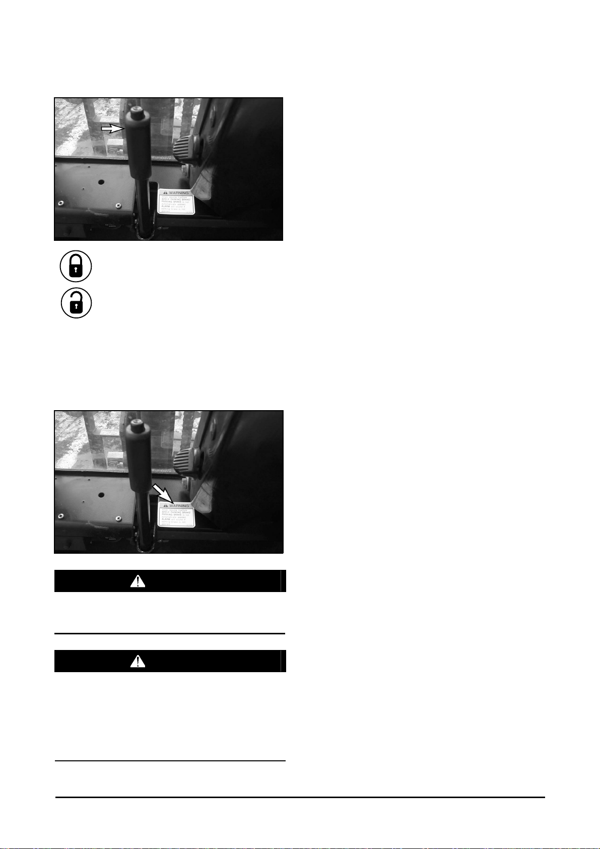
Parking brake
Pull the lever BACK to engage the
parking brake.
Push the lever FORWARD to release
the parking brake.
Applying the parking brake puts the transmission in
NEUTRAL. The parking brake must be applied
when leaving the lift truck and when starting the
engine. If the operator leaves the seat without
applying the parking brake, an audible alarm will
sound.
WARNING
When leaving machine apply parking brake!
Parking brake is not automatically applied.
Alarm will sound if parking brake is not applied.
WARNING
Correct adjustment is necessary to provide
adequate braking. See the MAINTENANCE section
for adjustment procedures. The lift truck may creep
at engine idle and can cause damage, injury or
death. Always apply the parking brake when
leaving the lift truck. The parking brake is NOT
automatically applied.
-9-

Safety Section
General Hazard Information
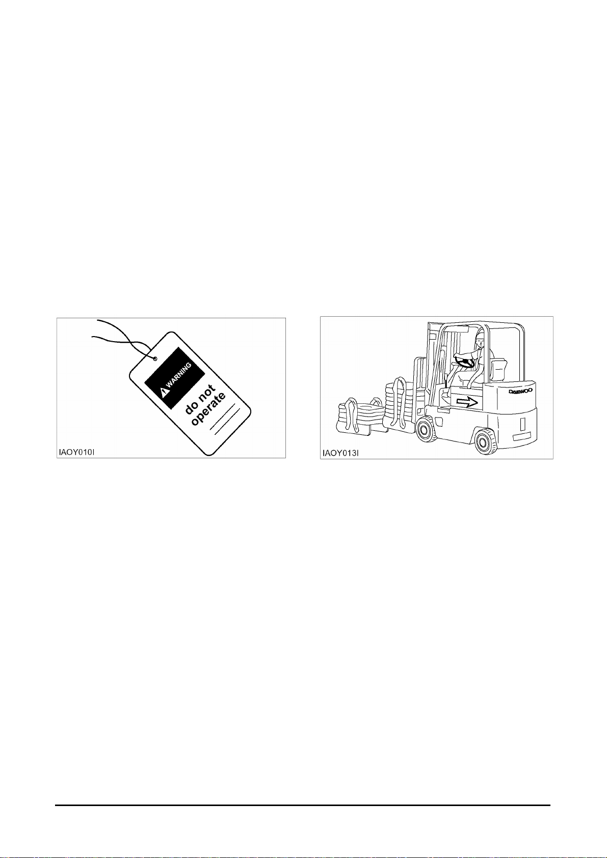
Attach a “Do Not Operate” or similar warning tag to
start switch or controls before servicing or repairing
the lift truck.
Do not start or service the lift truck when a “DO
NOT OPERATE” or similar warning tag is attached
to the start switch or controls.
Wear a hard hat, protective glasses and other
protective equipment as required by job conditions.
Know the width of your attachments so proper
clearance can be maintained when operating near
fences, boundary obstacles, etc.
Do not wear loose clothing or jewelry that can catch
on controls or other parts of the lift truck.
Keep the lift truck, especially the deck and steps,
free of foreign material such as debris, oil tools and
other items which are not part of the lift truck.
Secure all loose items such as lunch boxes, tools
and other items which are not part of the lift truck.
Know the appropriate work-site hand signals and
who gives them. Accept signals from one person
only.
Always use the overhead guard. The overhead
guard is intended to protect the lift truck operator
from overhead obstructions and from falling
objects.
A truck that is used for handing small objects or
uneven loads must be fitted with a load backrest.
If the lift truck must be operated without the
overhead guard in place due to low overhead
clearance, use extreme care. Make sure there is no
possibility of falling objects from any adjacent
storage or work area. Make sure the load is stable
and fully supported by the carriage and the load
backrest extension (if equipped).
Do not raise loads any higher than necessary and
never raise a load higher than 1830 mm (72 in) with
the overhead guard removed.
Always use load backrest extension when the
carriage or attachment does not fully support the
load. The load backrest extension is intended to
prevent the load or any part of the load from falling
backwards into the operator's station.
When operating the lift truck, do not depend only on
flashing lights or back-up alarm (if equipped) to
warn pedestrians.
Always be aware of pedestrians and do not
proceed until the pedestrians are aware of your
presence and intended actions and have moved
clear of the lift truck and/or load.
Do not drive lift truck up to anyone standing in front
of an object.
Obey all traffic rules and warning signs.
Keep hands, feet and head inside the operator
station. Do not hold onto the overhead guard while
operating the lift truck. Do not climb on any part of
the mast or overhead guard or permit others to do
so.
Do not allow unauthorized personnel to ride on the
forks or any other part of the lift truck, at any time.
When working in a building or dock, observe floor
load limits and overhead clearances.
-10-
Safety Section
Inhaling Freon gas through a lit cigarette or other
smoking method or inhaling fumes released from a
flame contacting Freon can cause bodily harm or
death. Do not smoke when servicing air
conditioners or wherever Freon gas may be
present.
Never put maintenance fluids into glass containers.
Use all cleaning solutions with care.
Do not use steam, solvent, or high pressure to
clean electrical components.
Report all needed repairs.
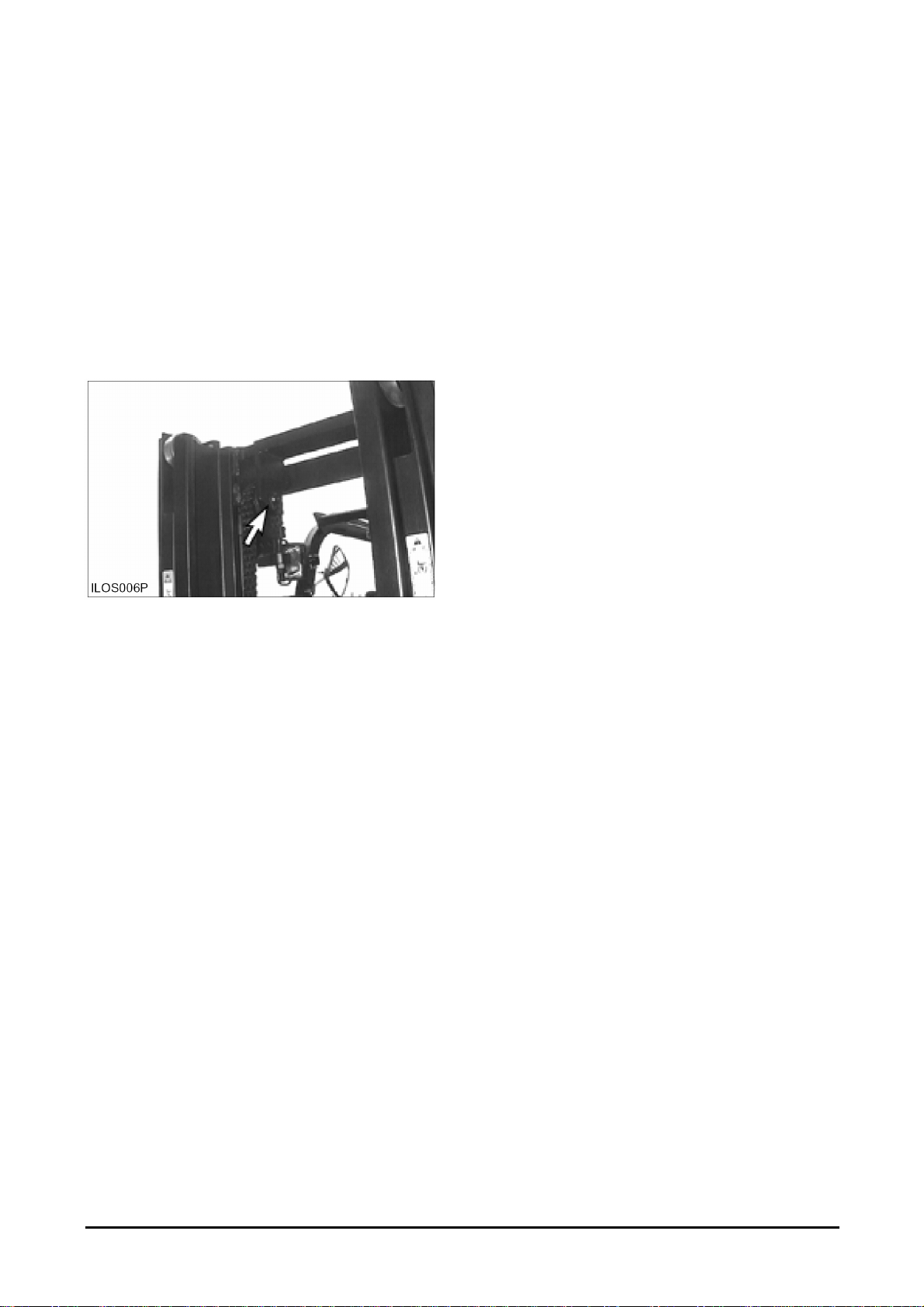
Inspect the part of the chain that is normally
operated over the crosshead roller. When the chain
bends over the roller, the movement of the parts
against each other causes wears.
Inspect to be sure that chain link pins do not extend
outside of the bore hole.
If any single link pin is extended beyond its
connecting corresponding link, it should be
suspected of being broken inside of its bore hole.
Inspect the chain anchor and the anchor links for
wear.
Do not change any factory set adjustment values
(including engine rpm setting) unless you have both
authorization and training. Especially Safety
equipment and switches may not be removed or
adjusted incorrectly. Repairs, adjustments and
maintenances that are not correct can make a
dangerous operating condition.
For any checkup, repair, adjustments, maintenance
and all other work concerning your forklift truck,
please contact your DAEWOO dealer. We would
like to draw your attention to the fact that any
secondary damages due to improper handling,
insufficient maintenance, wrong repairs or the use
of other than original DAEWOO spare parts waive
any liability by DAEWOO.
Operation Information
Mounting and Dismounting
Mount and dismount the lift truck carefully.
Clean your shoes and wipe your hands before
mounting.
Use both hands and face the lift truck when
mounting and dismounting.
Use the handgrips for mounting and dismounting.
Do not try to climb on or off the lift truck when
carrying tools or supplies.
Do not use any controls as handholds when
entering or leaving the operator's station.
Never get on or off a moving lift truck. Never jump
off the lift truck.
Keep hands and steering wheel free of slippery
material.
Before Starting the Lift Truck
Perform a walk-around inspection daily and at the
start of each shift. Refer to the topic “Walk-around
Inspection” in “Every 10 Service Hours or Daily”
section of this manual.
Adjust the seat so that full brake pedal travel can
be obtained with the operator's back against the
seat back.
Make sure the lift truck is equipped with a lighting
system as required by conditions.
Make sure all hydraulic controls are in the HOLD
position.
Make sure the direction control lever is in the
NEUTRAL position.
Make sure the parking brake is engaged.
Make sure no one is standing and/or working on,
underneath or close to the lift truck before operating
the lift truck.
Operate the lift truck and controls only from the
operator's station.
-11-
Safety Section
Make sure the lift truck horn, lights, backup alarm (if
equipped) and all other devices are working
properly.
Check for proper operation of mast and
attachments. Pay particular attention to unusual
noises or erratic movement which might indicate a
problem.
Make sure service and parking brakes, steering,
and directional controls are operational.
Make sure all personnel are clear of lift truck and
travel path.
Refer to the topic “Lift Truck Operation” in the
“Operation Section” of this manual for specific
starting instructions.
Starting the Lift truck
Operating the Lift Truck
Always keep the lift truck under control.
Obey all traffic rules and warning signs.
Never leave the lift truck with the engine operating,
or with the parking brake disengaged.
Operate the engine only in a well ventilated area.
Lower a mast, with or without load, before turning
or traveling. Tip over could result. Watch out for
overhead obstructions.
Always observe floor load limits and overhead
clearance.
Start, turn, and brake smoothly. Slow down for
turns, grades, slippery or uneven surfaces.
Do not start the engine or move any of the controls
if there is a “DO NOT OPERATE” or similar warning
tag attached to the start switch or controls.
Before Operating the Lift Truck
Test brakes, steering controls, horn and other
devices for proper operation. Report any faulty
performance. Do not operate lift truck until repaired.
Learn how your lift truck operates. Know its safety
devices. Know how the attachments work. Before
moving the lift truck, look around. Start, turn and
brake smoothly.
An operator must constantly observe his lift truck
for proper operation.
Use special care when operating on grades. Do not
angle across or turn on grades. Do not use lift truck
on slippery grades. Travel with forks downgrade
when unloaded. Travel with load upgrade.
Do not overload, or handle offset, unstable, or
loosely stacked loads. Refer to load capacity plate
on the lift truck. Use extreme caution when
handling suspended, long, high or wide load.
-12-
Tilt the elevated load forward only when directly
over unloading area and with load as low as
possible.
Do not stunt ride or indulge in horseplay.
Always look and keep a clear view of the path of
travel.
Travel in reverse if load or attachment obstructs
visibility. Use extreme caution if visibility is
obstructed.
Stay in designated travel path, clear of dock edges,
ditches, other drop-offs and surfaces which cannot
safely support the lift truck.
Slow down and use extra care through doorways,
intersections and other location where visibility is
reduced.
Slow down for cross aisles, turns, ramps, dips,
uneven or slippery surfaces and in congested areas,
avoid pedestrians, other vehicles, obstruction, pot
holes and other hazards or objects in the path of
travel.
Always use overhead guards except where
operation conditions do not permit. Do not operate
lift truck in high stacking areas without overhead
guards.
When stacking, watch for falling objects. Use load
backrest extension and overhead guard.
Refer to the topic “Operation Techniques” in the
“Operation Section” of this manual.
Safety Section
Loading or Unloading Trucks/Trailers
Do not operate lift trucks on trucks or trailers which
are not designed or intended for that purpose. Be
certain truck or trailer brakes are applied and wheel
chocks in place (or be certain unit is locked to the
loading dock) before entering onto trucks or trailers.
If trailer is not coupled to tractor, make sure the
trailer landing gear is properly secured in place. On
some trailers, extra supports may be needed to
prevent upending or corner dipping.
Be certain dock plates are in good condition and
properly placed and secured. Do not exceed the
rated capacity of dock boards or bridge plates.
Lift Truck Parking
When leaving the operator station, park the lift truck
in authorized areas only. Do not block traffic.
z Park the lift truck level, with the forks lowered and
the mast tilted forward until the fork tips touch the
floor.
z Move the direction control lever to NEUTRAL.
z Engage the parking brake.
z Turn the key switch off and remove the key.
z Turn the disconnect switch to OFF (if equipped).
z Block the drive wheels when parking on an
incline.
-13-

Safety Section
Maintenance Information
Perform all maintenance unless otherwise specified
as follows:
z Park the lift truck in authorized areas only.
z Park the lift truck level, with the forks lowered and
the mast tilted forward until the fork tips touch the
floor.
z Place the transmission controls in neutral.
z Engage the parking brake.
z Stop the engine.
z Remove the start switch key and turn the
disconnect switch OFF (if equipped).
z Block the drive wheels when parking on an
incline.
Pressure Air
Pressure air can cause personal injury. When using
pressure air for cleaning, wear a protective face
shield, protective clothing and protective shoes.
The maximum air pressure must be below 205 kPa
(30 psi) for cleaning purposes.
Fluid Penetration
Always use a board or cardboard when checking
for a leak. Escaping fluid under pressure, even a
pinhole size leak, can penetrate body tissue,
causing serious injury, and possible death. If fluid is
injected into your skin, it must be treated by a
doctor familiar with this type of injury immediately.
Crushing or Cutting Prevention
Support equipment and attachments properly when
working beneath them. Do not depend on hydraulic
cylinders to hold it up. Any attachment can fall if a
control is moved, or if a hydraulic line breaks.
Never attempt adjustments while the lift truck is
moving or the engine is running unless otherwise
specified.
Where there are attachment linkages, the
clearance in the linkage area will increase or
decrease with movement of the attachment.
Stay clear of all rotating and moving parts.
Keep objects away from moving fan blades.
They will throw or cut any object or tool that falls or
is pushed into them.
Do not use a kinked or frayed wire rope cable.
Wear gloves when handling the wire rope cable.
Retainer pins, when struck with force, can fly out
and injure nearby persons. Make sure the area is
clear of people when driving retainer pins.
Wear protective glasses when striking a retainer pin
to avoid injury to your eyes.
Chips or other debris can fly off objects when struck.
Make sure no one can be injured by flying debris
before striking any object.
Falling Objects Protective Structure (FOPS)
This is an attached guard located above the
operator's compartment and secured to the lift
truck.
To avoid possible weakening of the Falling Objects
Protective Structure (FOPS), consult a DAEWOO
dealer before altering, by adding weight to, welding
on, or cutting or drilling holes into the structure.
The overhead guard is not intended to protect
against every possible impact. The overhead guard
may not protect against some objects penetrating
into the operator's station from the sides or ends of
the lift truck.
The lift truck is equipped with an overhead guard
and FOPS as standard. If there is a possibility of
overhead objects falling through the guard, the
guard must be equipped with smaller holes or a
Plexiglas cover.
Any altering done that is not specifically authorized
by DAEWOO invalidates DAEWOO's FOPS
certification. The protection offered by this FOPS
will be impaired if it has been subjected to structural
damage. Structural damage can be caused by an
overturn accident, by falling objects, etc.
Do not mount any item such as fire extinguishers,
first aid kits and lights by welding brackets to or
drilling holes in any FOPS structure. See your
DAEWOO dealer for mounting guidelines.
-14-

Safety Section
Burn Prevention
Coolant
At operating temperature, the engine coolant is hot
and under pressure. The radiator and all lines to
heaters or the engine contain hot water or steam.
Any contact can cause severe burns.
Steam can cause personal injury.
Check the coolant level only after engine has been
stopped and the filter cap is cool enough to remove
with your bare hand.
Remove the cooling system filter cap slowly to
relieve pressure.
Cooling system additive contains alkali that can
cause personal injury. Avoid contact with the skin
and eyes and do not drink.
Allow cooling system components to cool before
draining.
Oils
Hot oil and components can cause personal injury.
Do not allow hot oil or components to contact the
skin.
At operation temperature, the hydraulic tank is hot
and can be under pressure.
Remove the hydraulic tank filter cap only after the
engine has been stopped and the filter cap is cool
enough to remove with your bare hand.
Remove the hydraulic tank filter cap slowly to
relieve pressure.
Relieve all pressure in air, oil fuel or cooling
systems before any lines, fittings or related items
are disconnected or removed.
Batteries
Batteries give off flammable fumes which can
explode.
Do not smoke when observing the battery
electrolyte levels.
Electrolyte is an acid and can cause personal injury
if it contacts skin or eyes.
Always wear protective glasses when working with
batteries.
Fire or Explosion Prevention
All fuels, most lubricants and some coolant
mixtures are flammable.
Fuel leaked or spilled onto hot surfaces or electrical
components can cause a fire.
Do not smoke while refueling or in a refueling area.
Do not smoke in areas where batteries are charged,
or where flammable materials are stored.
Batteries in series can be located in separate
compartments. When using jumper cables always
connect positive(+) cable to positive(+) terminal of
battery connected to starter solenoid and
negative(-) cable from external source to starter
negative(-) terminal.
(If not equipped with starter negative(-) terminal,
connect to engine block.)
See the Operation Section of this manual for
specific starting instructions.
Clean and tighten all electrical connections. Check
daily for loose or frayed electrical wires. Have all
loose or frayed electrical wires tightened, repaired
or replaced before operating the lift truck.
Keep all fuels and lubricants stored in properly
marked containers and away from all unauthorized
persons.
Store all oily rags or other flammable material in a
protective container, in a safe place.
Do not weld or flame cut on pipes or tubes that
contain flammable fluids. Clean them thoroughly
with nonflammable solvent before welding or flame
cutting on them.
Remove all flammable materials such as fuel, oil
and other debris before they accumulate on the lift
truck.
Do not expose the lift truck to flames, burning brush,
etc., if at all possible.
Shields, which protect hot exhaust components
from oil or fuel spray in the event of a line, tube or
seal failure, must be installed correctly.
Do not operate in areas where explosive gases
exist or are suspected.
-15-
Safety Section
Fire Extinguisher
Have a fire extinguisher-type BC and 1.5KG
minimum capacity-on rear overhead guard leg with
latch and know how to use it. Inspect and have it
serviced as recommended on its instruction plate.
Ether
Ether is poisonous and flammable.
Breathing ether vapors or repeated contact of ether
with skin can cause personal injury.
Use ether only in well-ventilated areas.
Do not smoke while changing ether cylinders.
Use ether with care to avoid fires.
Do not store replacement ether cylinders in living
areas or in the operator's compartment.
Do not store ether cylinders in direct sunlight or at
temperatures above 39°C (102°F).
Discard cylinders in a safe place. Do not puncture
or burn cylinders.
Keep ether cylinders out of the reach of
unauthorized personnel.
Lines, Tubes and Hoses
z End fittings damaged or leaking.
z Outer covering chafed or cut and wire reinforcing
exposed.
z Outer covering ballooning locally.
z Evidence of kinking or crushing of the flexible
part of hose.
z Armoring embedded in the outer cover.
z End fittings displaced.
Make sure that all clamps, guards and heat shields
are installed correctly to prevent vibration, rubbing
against other parts, and excessive heat during
operation.
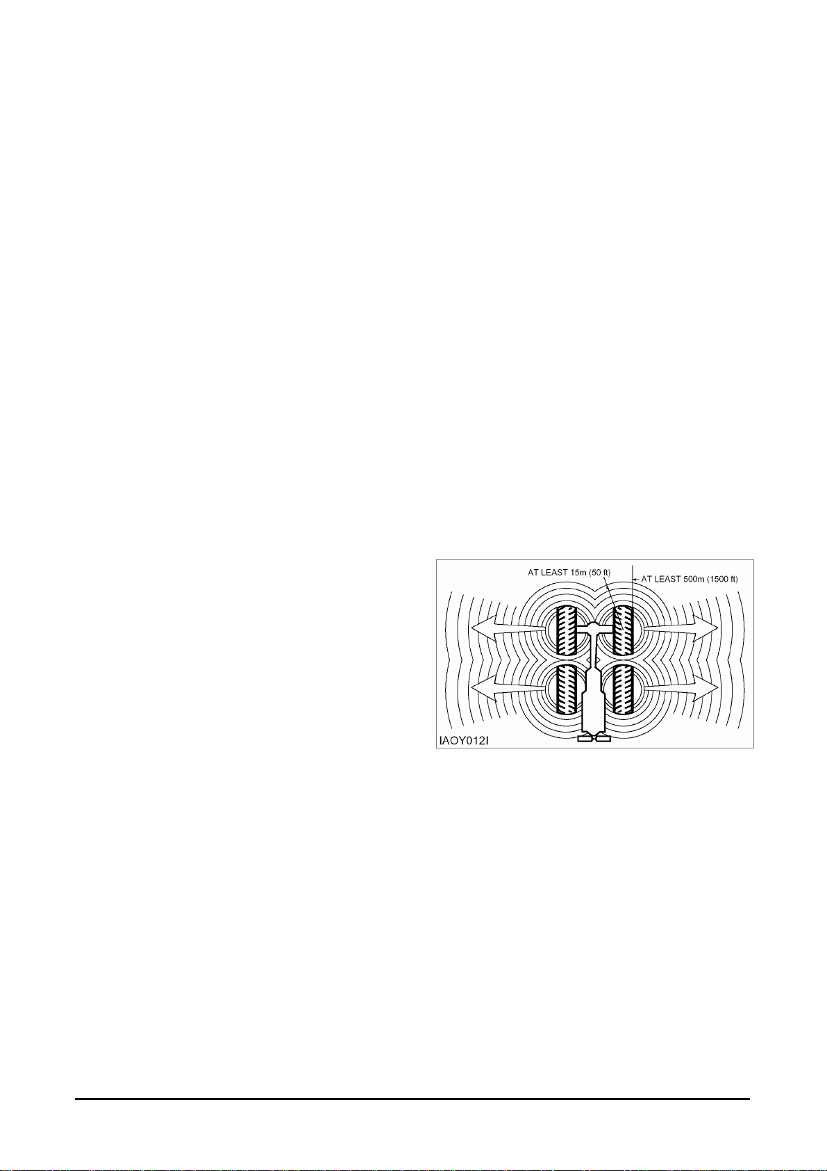
Tire Information
Explosions of air-inflated tires have resulted from
heat-induced gas combustion inside the tires. The
heat, generated by welding or heating rim
components, external fire, or excessive use of
brakes can cause gaseous combustion.
A tire explosion is much more violent than a
blowout. The explosion can propel the tire, rim and
axle components as far as 500 m (1500 ft) or more
from the lift truck. Both the force of the explosion
and the flying debris can cause personal injury or
death, and property damage.
Do not bend or strike high pressure lines. Do not
install bent or damaged lines, tubes or hoses.
Repair any loose or damaged fuel and oil lines,
tubes and hoses. Leaks can cause fires. Contact
your DAEWOO dealer for repair or replacement.
Check lines, tubes and hoses carefully. Do not use
your bare hand to check for leaks. Use a board or
cardboard to check for leaks. See Fluid Penetration
in the Safety Section for more details. Tighten all
connections to the recommended torque. Replace if
any of the following conditions are found.
Do not approach a warm tire closer than the
outside of the area represented by the shaded area
in the above drawing.
-16-
Safety Section
Dry nitrogen (N2) gas is recommended for inflation
of tires. If the tires were originally inflated with air,
nitrogen is still preferred for adjusting the pressure.
Nitrogen mixes properly with air.
Nitrogen inflated tires reduce the potential of a tire
explosion, because nitrogen does not support
combustion. Also, nitrogen helps prevent oxidation
and the resulting deterioration of rubber and
corrosion of rim components.
Proper nitrogen inflation equipment and training in
its use are necessary to avoid over-inflation. A tire
blowout or rim failure can result from improper or
misused equipment.
Stand behind the tread and use a self-attaching
chuck when inflation a tire.
Servicing, changing tires and rims can be
dangerous and should be done only by trained
personnel using proper tools and procedures. If
correct procedures are not followed while servicing
tires and rims, the assemblies could burst with
explosive force and cause serious personal injury
or death. Follow carefully the specific information
provided by your tire or rim servicing personnel or
dealer.
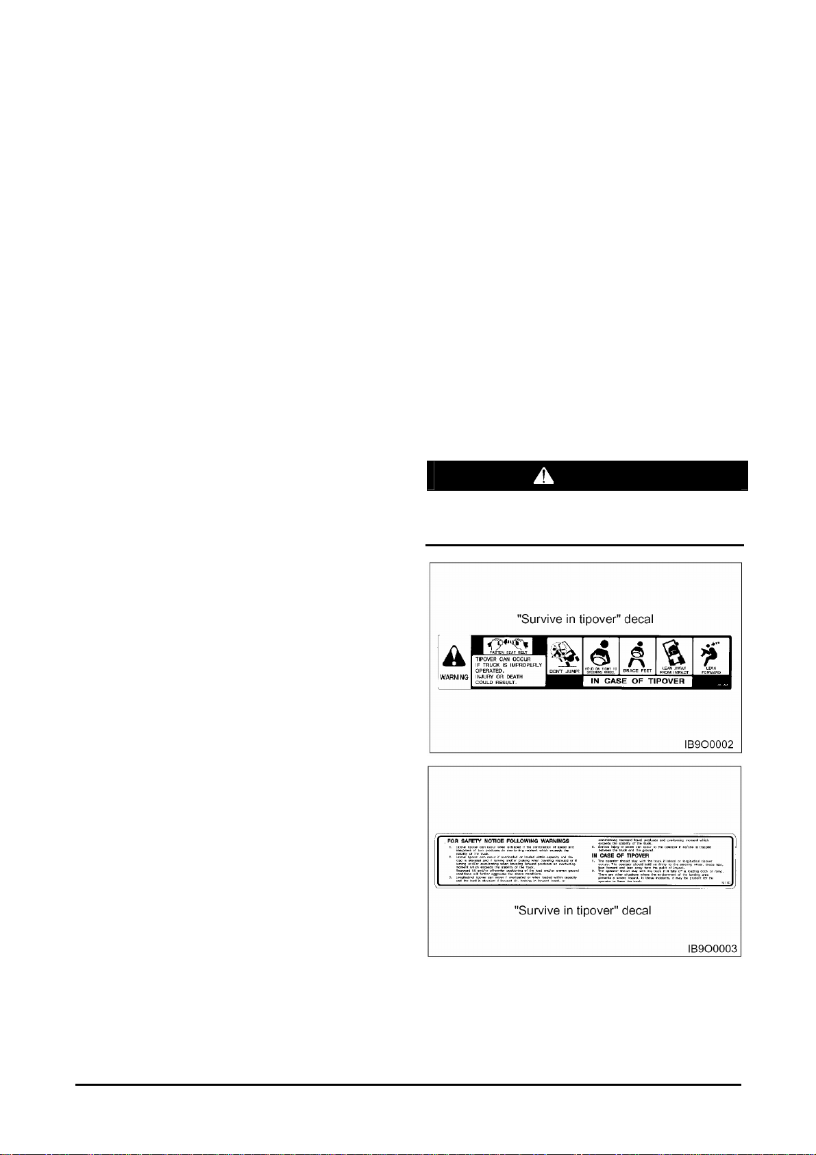
Operator Restraint System(If
Equipped)
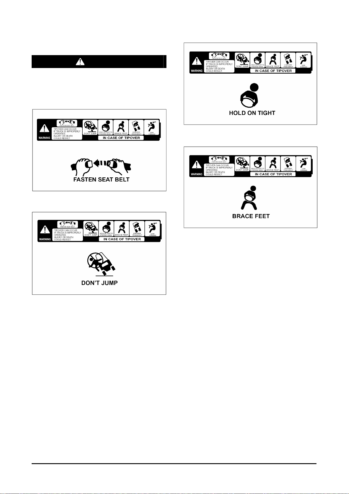
Warning Signs and Labels
Your DAEWOO lift truck has the following tipover
warning decals.
Make sure that you can read all safety signs. Clean
or replace these if you cannot read the words or
see the pictures. When cleaning the labels use a
cloth, water and soap. Do not use solvent, gasoline,
etc. You must replace a label if it is damaged,
missing or cannot be read. If a label is on a part
that is replaced, make sure a new label is installed
on the replaced part. See you DAEWOO Lift Truck
dealer for new labels.
The most effective method of preventing serious
injury or death to yourself or others is to familiarize
yourself with the proper operation of the lift truck, to
be alert, and to avoid actions or conditions which
can result in an accident.
WARNING
Tipover can occur if the truck is improperly
operated. In the event of tipover, injury or death
could result.
-17-
Safety Section
The “Survive in tipover” warning is located on the
overhead guard. It shows the proper use of the
operator restraint system.
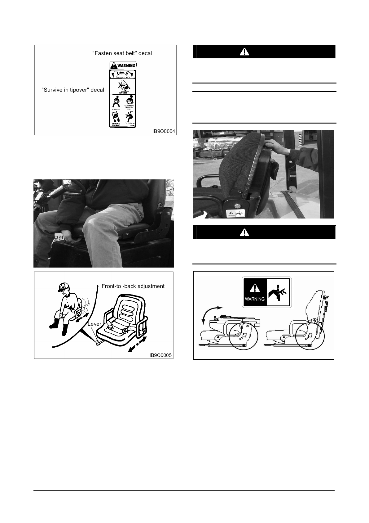
Seat Adjustment
WARNING
Do NOT place your hand or fingers under the
seat. Injury may occur as the seat suspension
mechanism moves up and down.
NOTICE
Before getting on the truck, adjust the level of the
suspension using the grip in the rear of the seat.
Move the lever, slide the seat to the desired
position, and release the lever.
Adjust the seat before operating the lift truck. After
adjusting, set the seat to make sure it is properly
locked. DO NOT adjust the seat while the truck is in
motion.
WARNING
When raising and lowering the seat backrest,
avoid placing hand or fingers in the hinge area
indicated by the circle. Injury may occur.
-18-
Safety Section
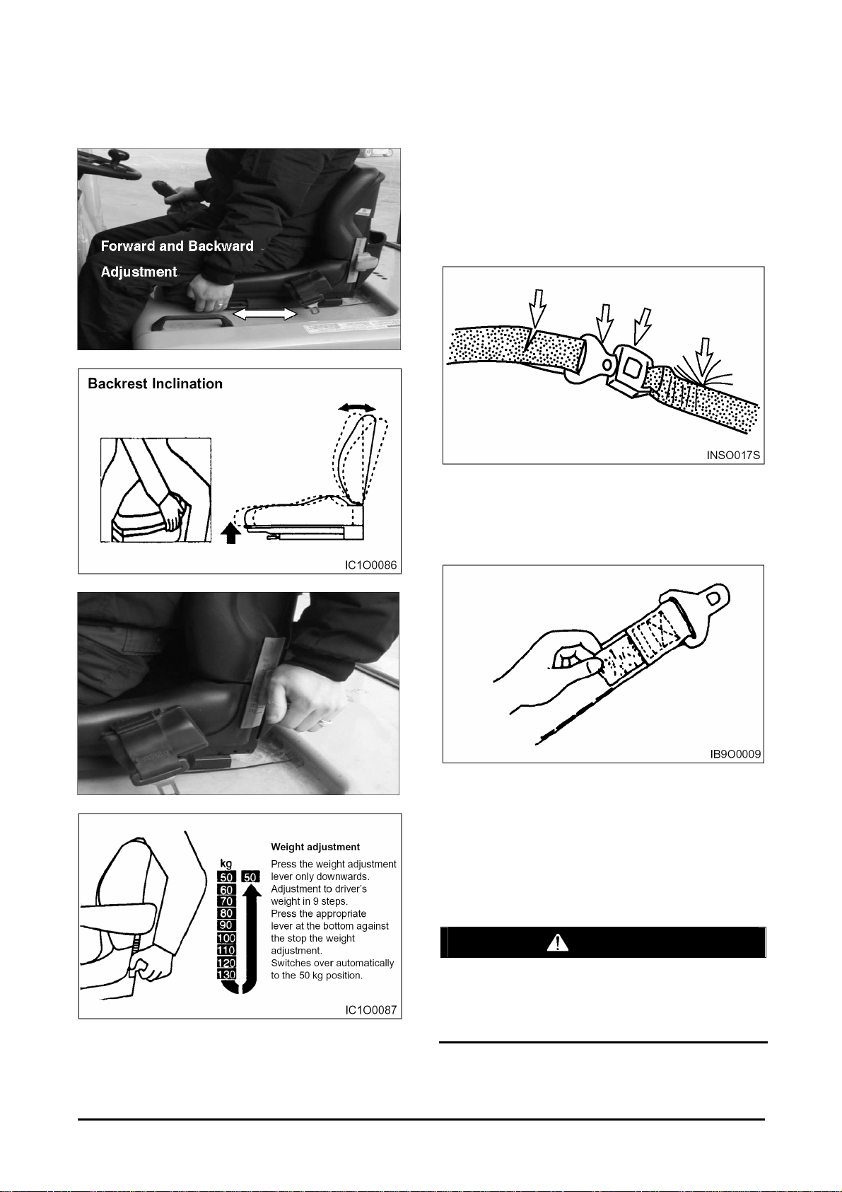
If Optional Suspension Seat (weight
adjusting type) Equipped
Seat Belt
The Operator Restraint System, Prevents the
operator from jumping from the operator’s
compartment in the event of a forward or side
tipover. The system is designed to keep the
operator on the seat and in the operator’s
compartment in the event of a tipover.
Inspection
1. If the seat belt is torn, if pulling motion is
interrupted during extension of the belt, or if the
belt cannot be inserted into the buckle properly,
replace the seat belt assembly.
2. Belt Maintenance - Every 500 service hours.
Check that the belt fastening works properly
and that winding device is free from run lock
when jerked. Check that the belt is suitably
fastened to the seat. Check that the seat is
correctly secured to the hood and the chassis.
On visual inspection, fastenings must be intact,
otherwise, contact the safety manager.
WARNING
Your DAEWOO truck comes equipped with a
DAEWOO operator restraint system. Should it
become necessary to replace the seat for any
reason, it should only be replaced with another
DAEWOO operator restraint system.
-19-
Safety Section
3. In the event of a tipover, the seat and restraint
system should be inspected for damage and
replaced, if necessary.
NOTE: Operator restraints shall be examined at
the regular truck service intervals. It is
recommended that they be replaced if any
of the following conditions are found:
Cut or frayed strap Worn or damaged hardware
including anchor points Buckle or retractor
malfunction
z Loosen stitching
WARNING
The seat belt may cause the operator to bend at
the waist. If you are pregnant or have suffered
from some abdominal disease, consult a doctor
before you use the seat belt.
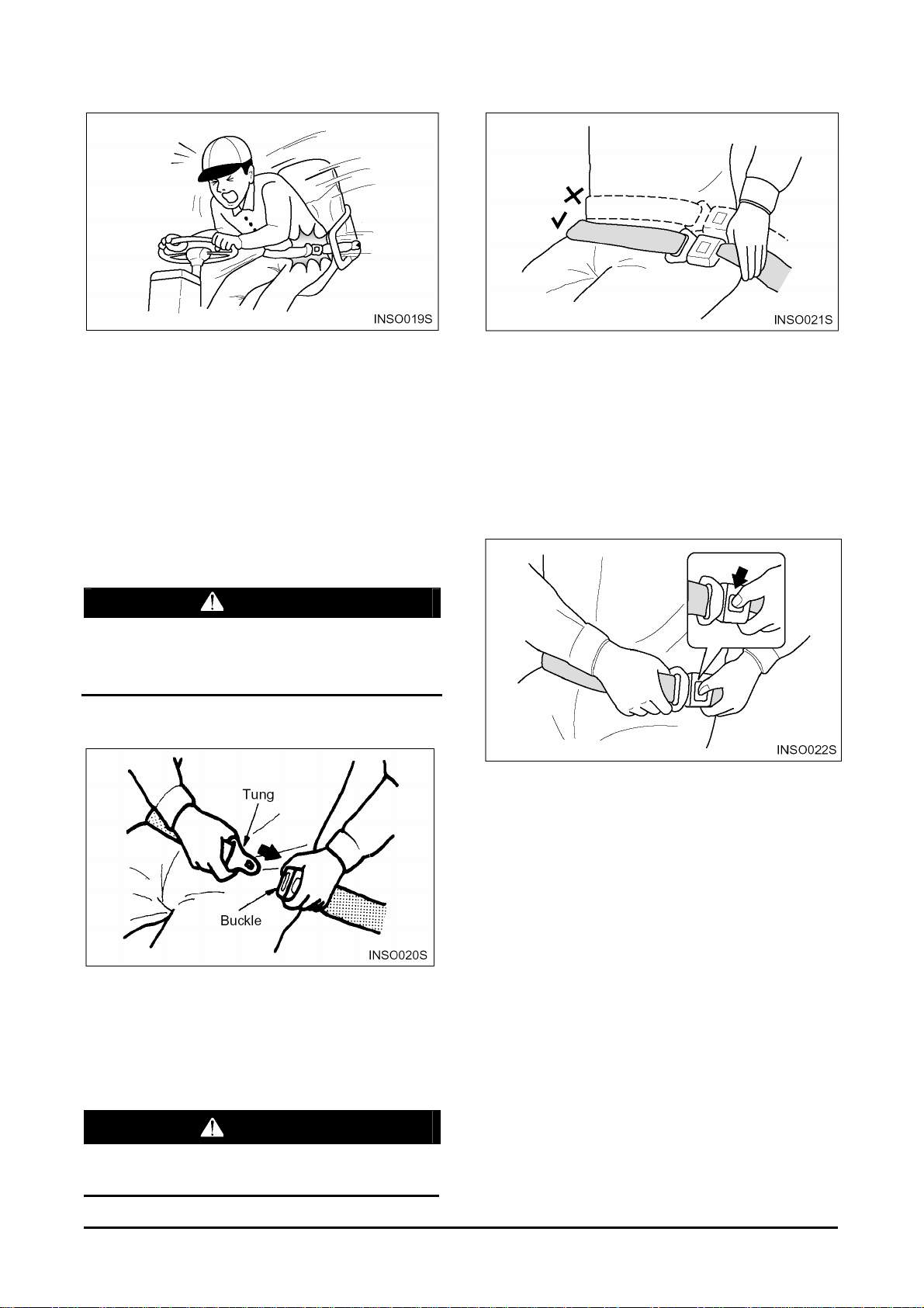
Fasten the Seat Belt
4. Be sure to fasten the belt across your hips, not
across your abdomen.
NOTE: The belt is designed to automatically adjust
to your size and movement. A quick pull on
the belt will confirm that the automatic
adjuster will hold the belt position in the
event of an accident.
Release the Seat Belt
Push the button of the buckle to release the belt.
The belt will automatically retract when released.
Hold the plate of the belt and allow the belt to
slowly retract.
1. Grip the plate (connector) of the belt and pull the
belt from the retractor. Then insert the plate into
the slot of the buckle until a snap is heard. Pull
on the belt to confirm it is latched.
2. Make sure the belt is not twisted.
WARNING
If you fasten the belt across your abdomen, the
belt may injure your abdomen in an accident.
-20-
Safety Section
Avoiding Lift Truck Tipover
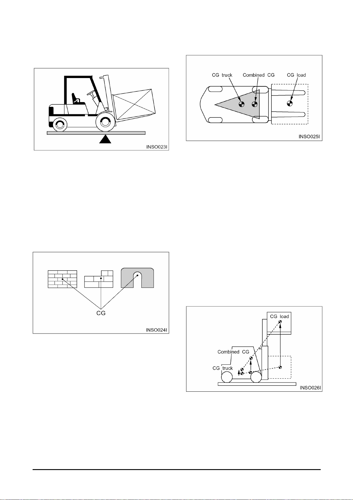
Lift Truck Stability
Counterbalanced lift truck design is based on the
balance of two weights on opposite sides of a
fulcrum (the front axle). The load on the forks must
be balanced by the weight of the lift truck. The
location of the center of gravity of both the truck
and the load is also a factor. This basic principle is
used for picking up a load. The ability of the lift
truck to handle a load is discussed in terms of
center of gravity and both forward and sideways
stability.
Center of Gravity (CG)
Stability and Center of Gravity
The stability of the lift truck is determined by the
location of its CG; or, if the truck is loaded, the
combined CG of the truck and load. The lift truck
has moving parts and, therefore, has a CG that
moves. The CG moves forward or backward as the
mast is tilted forward or backward. The CG moves
up or down as the mast moves up or down. The CG
and, therefore, the stability of the loaded lift truck,
are affected by a number of factors such as:
z the size, weight, shape and position of the load
z the height to which the load is lifted
z the amount of forward or backward tilt
z tire pressure
z dynamic forces created when the lift truck is
accelerated, braked or turned
z condition and grade of surfaces on which the lift
truck is operated
The point within an object, at which the whole
weight of the object may be regarded as being
concentrated, is called the center of gravity or CG.
If the object is uniform, its geometric center will
coincide with its CG. If it is not uniform, the CG
could be at a point outside of the object. When the
lift truck picks up a load, the truck and load have a
new combined CG.
These same factors are also important for unloaded
lift trucks. They tip over sideways easier than a
loaded lift truck carrying its load in the lowered
position.
-21-
Safety Section
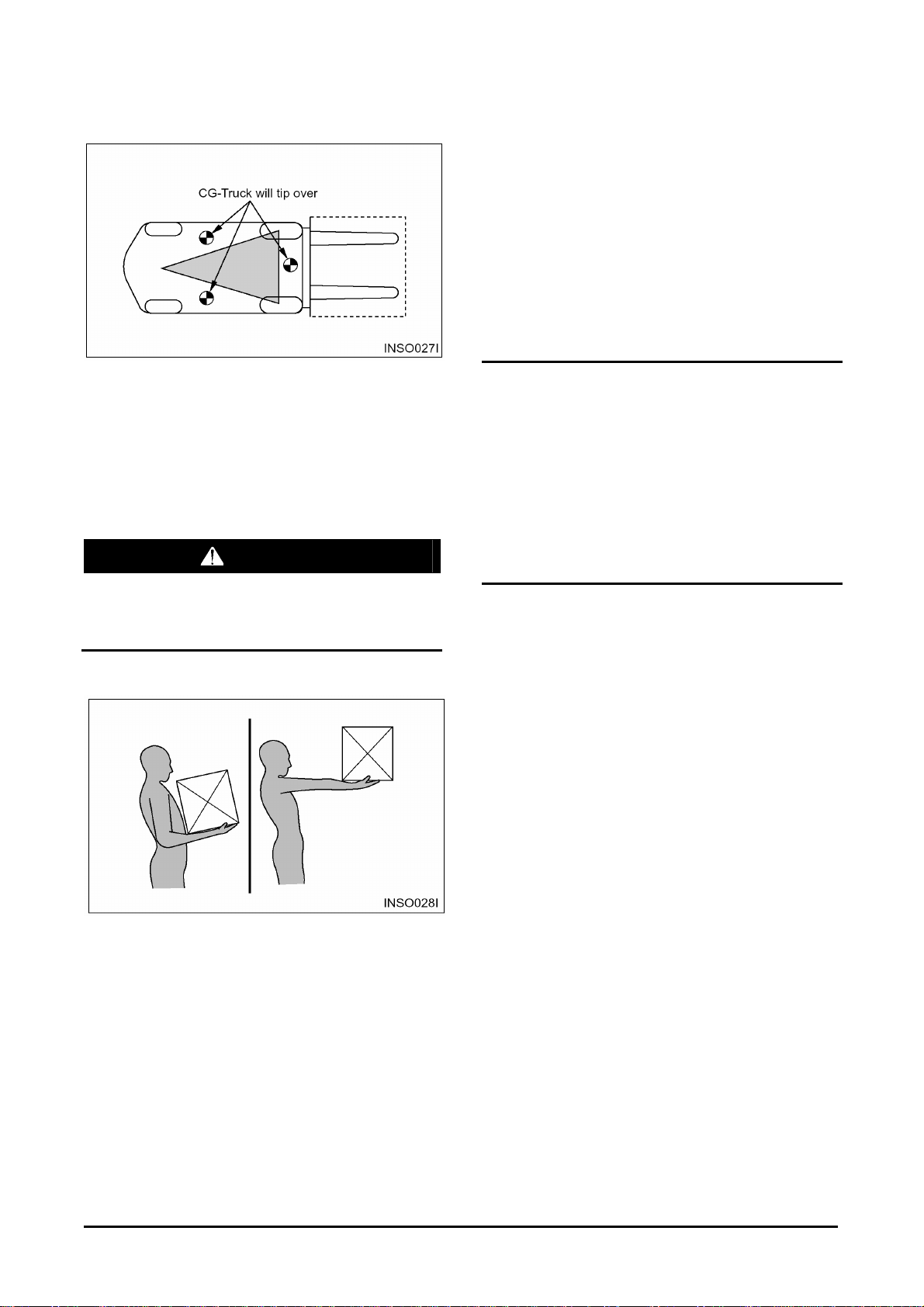
Lift Truck Stability Base
For the lift truck to be stable (not tip over forward or
to the side), the CG must stay within the area of the
lift truck stability base – a triangular area between
the front wheels and the pivot of the steer wheels. If
the CG moves forward of the front axle, the lift truck
will tip forward. If the CG moves outside of the line
on either side of the stability base, the lift truck will
tip to the side.
WARNING
Dynamic forces (braking, acceleration, turning)
also affect stability and can produce tipover
even when the CG is within the stability
triangle.
mast, and having no special-purpose attachment.
In addition, the capacity load assumes that the load
center is no further from the top of the forks than it
is from the face of the backrest. If these conditions
do not exist, the operator may have to reduce the
safe operating load because the truck stability may
be reduced. The lift truck should not be operated if
its capacity/nameplate does not indicate capacity
load.
NOTE: If the load is not uniform, the heaviest
portion should be placed closer to the
backrest and centered on the forks.
NOTICE
1. Capacity/Nameplates originally attached to
forklifts sold by DAEWOO shall not be removed,
altered or replaced without DAEWOO’s approval.
2. DAEWOO assumes no responsibility for lift
trucks placed in service without a valid DAEWOO
Nameplate.
3. If necessary to change your specification, contact
your DAEWOO lift truck dealer.
Capacity Load (Weight and Load Center)
The capacity load of the lift truck is shown on the
capacity/nameplate riveted to the truck. It is
determined by the weight and load center. The load
center is determined by the location of the CG of
the load.
The load center shown on the nameplate is the
horizontal distance from the front face of the forks,
or the load face of an attachment, to the CG of the
load. The location of the CG in the vertical direction
is the same as the horizontal dimension.
Remember that, unless otherwise indicated, the
capacity load shown on the nameplate is for a
standard lift truck with standard backrest, forks and
-22-
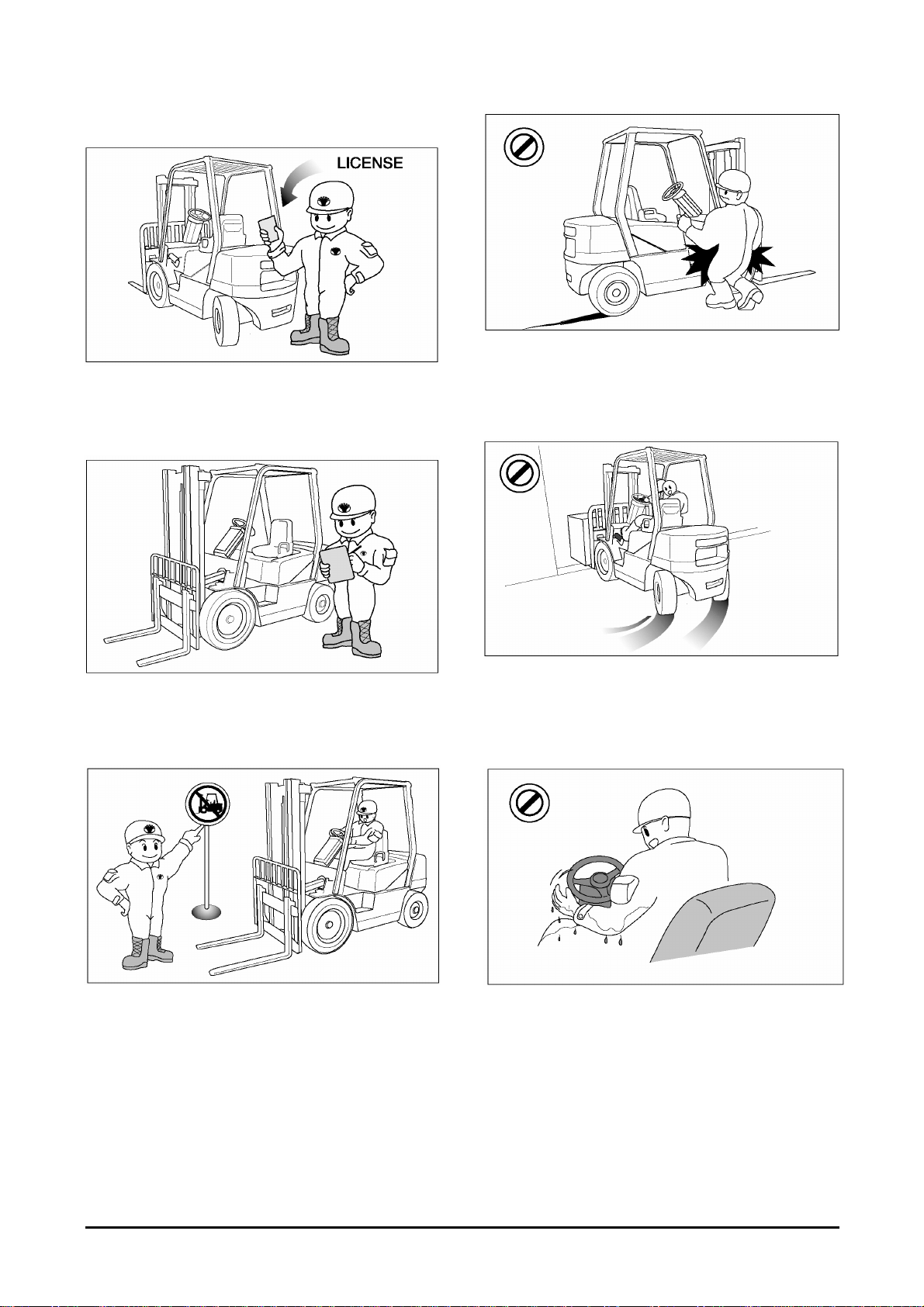
Safety Rules
Only properly trained and authorized personnel
should operate forklift trucks. Wear a hard hat and
safety shoes when operating a lift truck. Do not
wear loose clothing.
Safety Section
Do not operate a lift truck unless you are in the
operator's seat.
Keep arms, legs and head inside the confines of
the operator's area. Keep hands and feet out of the
mast assembly.
Inspect and check the condition of your forklift truck
using the operator's check list before starting work.
Immediately report to your supervisor any obvious
defects or required repairs.
Do not operate your truck in unauthorized areas.
Know your forklift truck and think safety.
Do not compromise safety.
Follow all safety rules and read all warning signs.
Do not start, stop, turn or change direction
suddenly or at high speed. Sudden movement can
cause the lift truck to tip over. Slow the speed of
your truck and use the horn near corners, exits,
entrances, and near people.
Never operate a lift truck with wet hands or shoes.
Never hold any controls with grease on your hands.
Your hands or feet will slide off of the controls and
cause an accident.
-23-
Safety Section
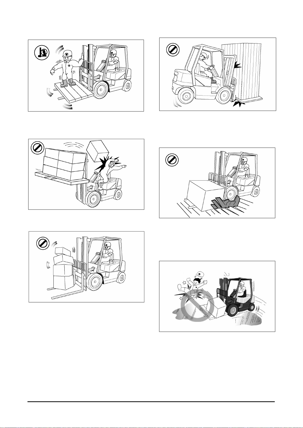
Do not raise anyone on the forks of your lift truck
unless using an approved safety cage.
Do not let other people ride on the truck.
Lift trucks are designed to carry loads, not people.
Do not operate your truck without the load backrest
extension and overhead guard. Keep the load
against the backrest with the mast tilted backward
Do not overload. Always handle loads within the
rated capacity shown on the capacity plate.
Do not add extra counterweight to the truck. An
overload can cause the truck to roll over and cause
injury to personnel and damage to the lift truck.
Do not drive on soft ground.
Observe all signs, especially those on maximum
permitted floor loadings, elevator capacities and
clearance heights.
Handle loads carefully and check them closely for
stability and balance.
Do not lift or move loads that are not safe. Do not
pick up an off center load. Such a load increases
the possibility of a tipover to the side. Make sure
loads are correctly stacked and positioned across
both forks. Always use the proper size pallet.
Position the forks as wide as possible under the
load. Position loads evenly on the forks for proper
balance. Do not lift a load with one fork.
Do not drive on slippery surfaces.
Sand, gravel, ice or mud can cause a tipover.
If unavoidable, slow down.
-24-
Safety Section
Do not permit anyone to stand or walk under the
load or lifting mechanism. The load can fall and
cause injury or death to anyone standing below.
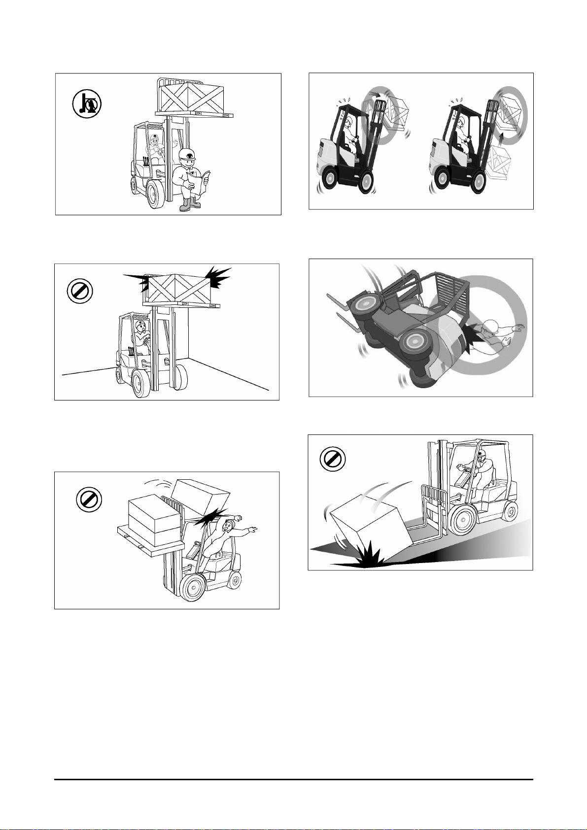
Look out for overhead obstructions when raising or
stacking loads. Do not travel with a raised load. Do
not travel with the mast raised. The lift truck can roll
over and cause injury or death to you or other
personnel.
Do not elevate the load with the mast tilted forward.
Do not tilt the elevated loads forwards.
This will cause the lift truck to tip over forward.
Do not jump off if your truck starts to tip over.
Stay in your seat to survive.
Do not move loose loads that are higher than the
load backrest.
Be alert for falling loads when stacking.
Travel with the load tilted back and the forks as low
as possible.
This will increase stability to the truck and load and
permit better visibility for you.
Go up ramps in forward direction and down ramps
in reverse direction when moving loads.
Never elevate a load with the forklift truck on an
incline.
Go straight off and straight down. Use an assistant
when going up or down a ramp with a bulky load.
-25-
Safety Section
Do not stack or turn on ramps.
Do not attempt to pick-up or deposit a load unless
the lift truck is level. Do not turn on or drive across
an incline.
Do not go over rough terrain. If unavoidable, slow
down.
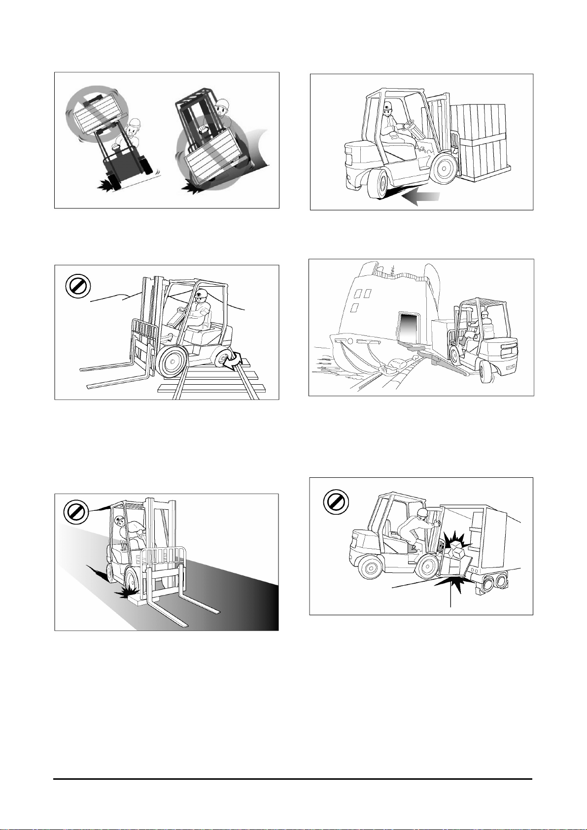
Cross railroad tracks slowly and diagonally
whenever possible. A railroad crossing can give a
loaded forklift truck a real jolt. For smoother
crossing, cross the railroad diagonally so one wheel
crosses at a time.
Do not drive in forward direction when loads restrict
your visibility. Operate your lift truck in reverse to
improve visibility except when moving up a ramp.
Be careful when operating a lift truck near the edge
of a loading dock or ramp. Maintain a safe distance
from the edge of docks, ramps and platforms.
Always watch tail swing.
The truck can fall over the edge and cause injury or
death.
Avoid running over loose objects.
Look in the direction of travel. Look out for other
persons or obstructions in your path of travel.
An operator must be in full control of his lift truck at
all times.
Do not operate on bridge plates unless they can
support the weight of the truck and load.
Make sure that they are correctly positioned.
Put blocks on the vehicle you enter to keep it from
moving.
-26-
Safety Section
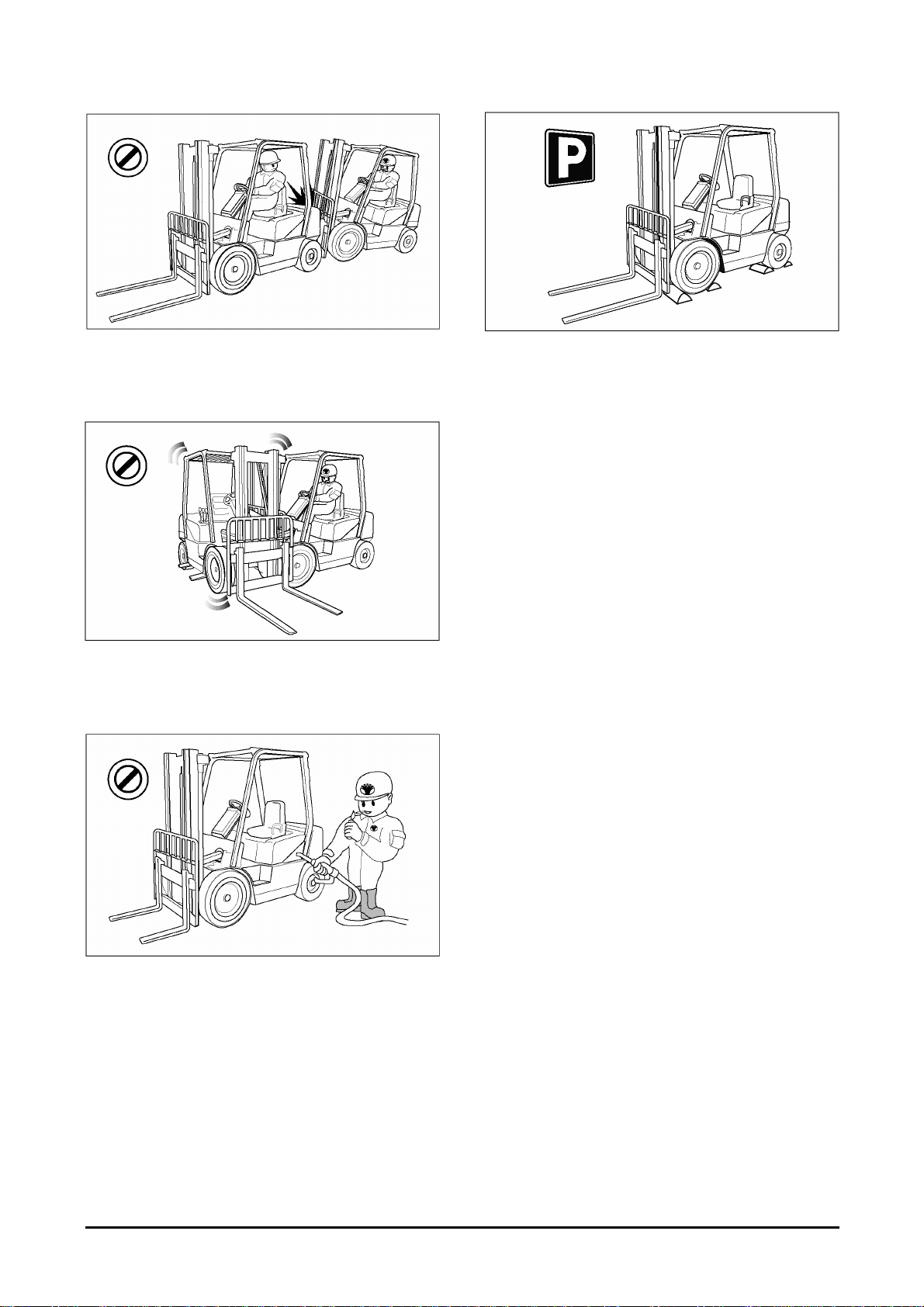
Do not operate your truck close to another truck.
Always keep a safe distance from other trucks and
make sure there is enough distance to stop safely.
Never overtake other vehicles.
Do not use your lift truck to push or tow another
truck.
Do not let another push or tow your truck.
If a truck will not move, call a service technician.
Park your lift truck in authorized areas only. Fully
lower the forks to the floor, put direction lever in
NEUTRAL position, engage the parking brake, and
turn the key to the OFF position. Remove the key
and put blocks behind the wheels to prevent the
truck from rolling. Shut off your forklift truck when
leaving it unattended.
Check the condition of your forklift truck after the
day's work.
Forklift trucks may only be refueled at specially
reserved locations. Switch off the engine when
refueling.
Smoking and handling of naked flames during
refueling are strictly prohibited. This prohibition also
applies during the changing of the LPG (liquefied
propane gas) tank.
Mop up spilt fuel and do not forget to close the fuel
tank before restarting the engine.
-27-
Safety Section
How to Survive in a Tipover
WARNING
In the event of a tipover, the risk of serious injury or
death will be reduced if the operator is using the
operator restraint system and follows the
instructions provided.
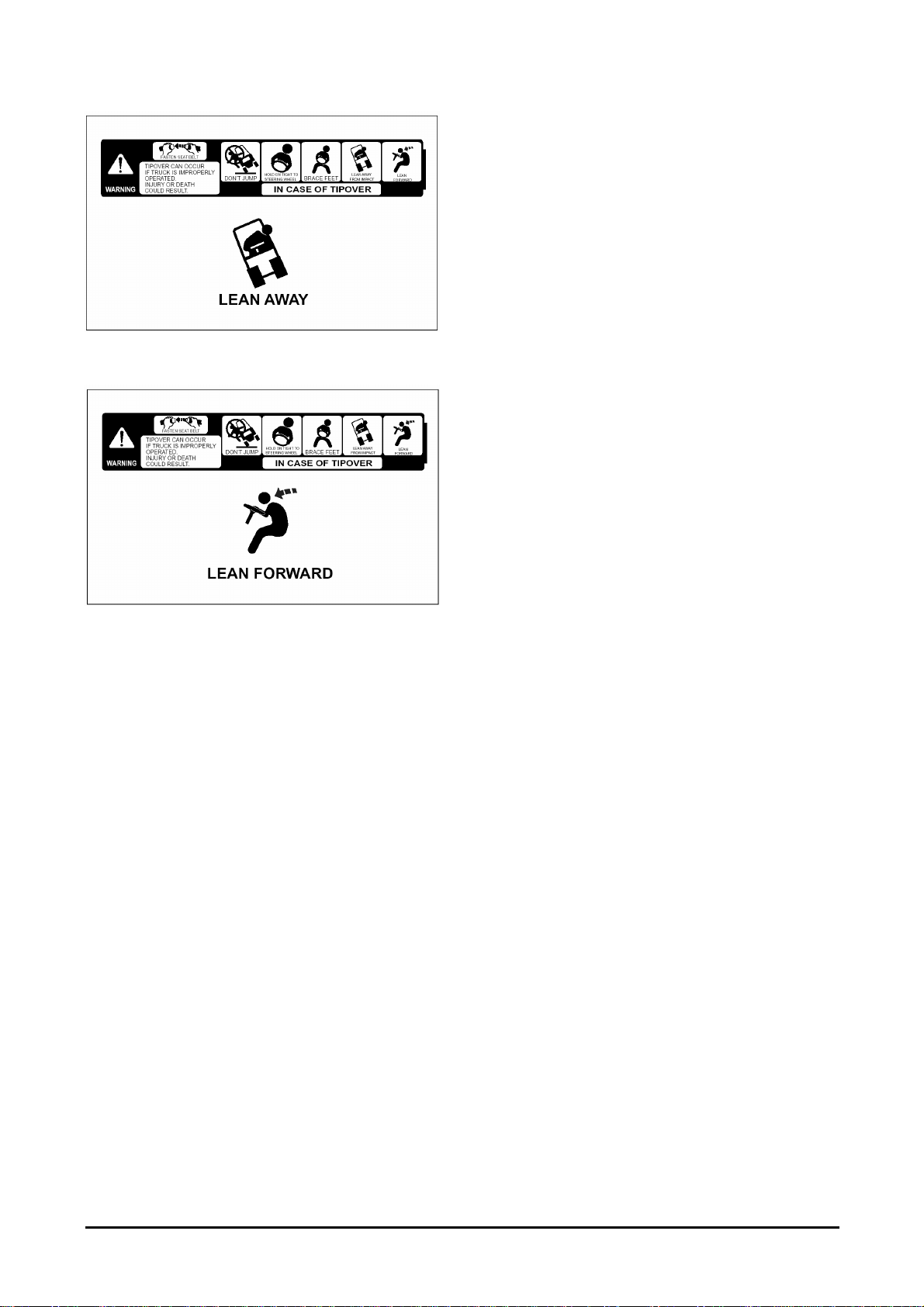
Always use operator restraint system.
DON’T jump.
Hold on tight.
Brace your feet and keep them within the operator’s
compartment.
-28-
Safety Section
Lean away from the direction of fall.
Lean forward.
-29-

General Section
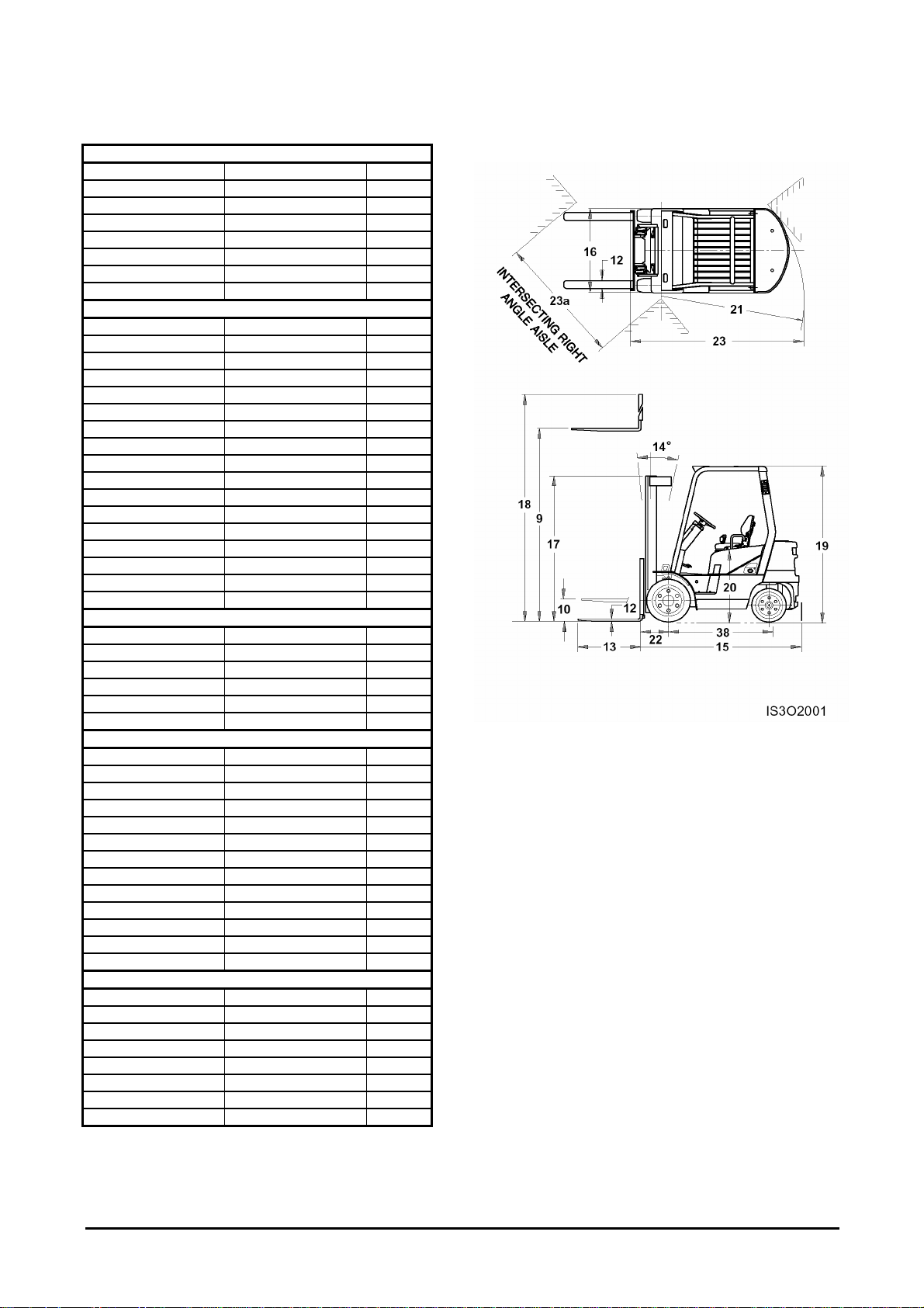
Specifications
CHARACTERISTICS
Manufacturer
1
Model
2
Capacity at rated load center
3
Load center distance
4
Power type electric, diesel, gasoline, LPG
5
Operator type stand-on, rider seated
6
Tires* c = cushion, p = pneumatic
7
Wheels (x = driven) number, front/rear
8
DIMENSIONS
9
Lift with STD
10
two - stage mast
11
Fork carriage
12
Forks
Tilt of mast
14
15
16
17
Overall
dimensions
18
19
20
Outside turning radius
21
Load moment constant (from center of front wheel to fork face)
22
90° stacking aisle (add load length and clearance)
23
90° intersecting aisle
23a
maximum fork height with rated load
free lift
special free lift
ISO class
thickness X width X length
fork spacing (minimum X maximum)
forward/backward
length without forks
width
mast lowered height
mast extended height
overhead guard height
seat height
PERFORMANCE
24
Speeds
25
26
Drawbar pull
28
Gradeability
30
Acceleration time
31
travel, loaded/unloaded
lift, loaded/unloaded
lowering, loaded/unloaded
at 1.6 km/h, loaded/unloaded
at 1.6 km/h, loaded/unloaded
traveling loaded/unloaded
WEIGHT
Total weight at unloaded
32
33
34
Axle load
with load front/rear
without load front/rear
CHASSIS
35
Tires
36
37
Wheelbase
38
Tread front/rear
39
40
Ground clearance
41
Service brake
42
Parking brake
43
number of front/rear
front size
rear size
at the lowest point
at the center of wheelbase
DRIVE
Battery voltage/capacity
45
49
50
51
52
53
55
56
Engine
Transmission
manufacturer/model
rated output (at rpm) gas/LPG
max. torque (at rpm) gas/LPG
cycle/cylinders/displacement
fuel consumption
type
number of speeds forward/reverse 1/1 1/1
* Solid soft rider tires are available instead of pneumatic as an option.
DHI&M DHI&M
D20S-3 D25S-3
kg 2000 2500
mm 500 500
mm 3230 3230
mm 152 152
mm
ll ll
mm 45 X 100 X 1050 45 X 100 X 1050 13
mm 275 X 1035 275 X 1035
deg 6/10 6/10
mm 2505 2573
mm 1170 1170
mm 2170 2170
mm 4470 4470
mm 2183 2183
mm 1026 1026
mm 2220 2265
mm 485 485
mm 2705 2750
mm 1970 2000
km/h 19.5/20 19.4/19.9
mm/s 550/600 530/600
mm/s 510/460 510/460
kg 1610/ 1620/
% 28.6/ 24.9/
s
kg 3910 4280
kg 5180/730 5925/855
kg 1970/1940 1910/2370
mm 1625 1625
mm 975/1000 975/1000
mm 115 115
mm 153 153
V/AH 12/85 12/85
kW 44.1(2300) 44.1(2300)
kg - m 20(1600) 20(1600)
cc 4/4/3268 4/4/3268
l/hr
diesel diesel
rider - seated rider - seated
p p
X2/2 X2/2
2/2 2/2
7.00 X 15 - 12PR 7.00 X 15 - 12PR
6.50 X 10 - 10PR 6.50 X 10 - 10PR
foot/hydraulic foot/hydraulic
hand/mechanical hand/mechanical
DHI&M/DB33A DHI&M/DB33A
Powershift Powershift
-30-
DHI&M DHI&M 1
D30S-3 D32S-3 2
3000 3000(6500lb) 3
500 600(24in) 4
diesel diesel 5
rider - seated rider-seated 6
p p 7
X2/2 X2/2 8
3230 3230 9
152 152 10
11
lll lll 12
45 X 125 X 1050 45X125X1050
286 X 1044 286X1044 13
6/10 6/10 14
2636 2690 15
1197 1197 16
2160 2160 17
4470 4470 18
2183 2183 19
1026 1026 20
2364 2414 21
485 485 22
2849 2899 23
2050 2100 23a
19.2/19.7 19.0/19.5 24
520/600 520/600 25
510/460 510/460 26
1705/ 1705/ 28
23.0/ 23/ 30
31
4715 5070 32
6705/1010 6810/1260 33
1890/2825 1810/3260 34
2/2 2/2 35
28 X 9 X 15 - 12PR 28X9X15-12PR 36
6.50 X 10 - 10PR 6.50X10⁻¹⁰PR 37
1625 1625 38
982/1000 982/1000 39
105 105 40
153 153 41
foot/hydraulic foot/hydraulic 42
hand/mechanical hand/mechanical 43
12/85 12/85 45
DHI&M/DB33A DHI&M/DB33A 49
44.1(2300) 44(2300) 50
20(1600) 20/1600 51
4/4/3268 4/4/3268 52
53
Powershift Powershift 55
1/1 1/1 56
General Section
-31-

General Section
Specifications
CHARACTERISTICS TIER - II
Manufacturer
1
Model
2
Capacity at rated load center
3
Load center distance
4
Power type electric, diesel, gasoline, LPG
5
Operator type stand-on, rider seated
6
Tires* c = cushion, p = pneumatic
7
Wheels (x = driven) number, front/rear
8
kg 2000 2500
mm 500 500
DIMENSIONS
9
Lift with STD
10
two - stage mast
11
Fork carriage
12
Forks
13
Tilt of mast
14
15
16
17
Overall dimensions
18
19
20
Outside turning radius
21
Load moment constant (from center of front wheel to fork face)
22
90° stacking aisle (add load length and clearance)
23
90° intersecting aisle
23a
maximum fork height with rated load
free lift
special free lift
ISO class
thickness X width X length
fork spacing (minimum X maximum)
forward/backward
length without forks
width
mast lowered height
mast extended height
overhead guard height
seat height
mm 3230 3230
mm 152 152
mm
ll ll
mm 45 X 100 X 1050 45 X 100 X 1050
mm 275 X 1035 275 X 1035
deg 6/10 6/10
mm 2505 2573
mm 1170 1170
mm 2170 2170
mm 4470 4470
mm 2183 2183
mm 1026 1026
mm 2220 2265
mm 485 485
mm 2705 2750
mm 1970 2000
PERFORMANCE
24
Speeds
25
26
Drawbar pull
28
Gradeability
30
Acceleration time
31
travel, loaded/unloaded
lift, loaded/unloaded
lowering, loaded/unloaded
at 1.6 km/h, loaded/unloaded
at 1.6 km/h, loaded/unloaded
traveling loaded/unloaded
km/hr 19.5/20 19.5/20
mm/s 550/600 530/600
mm/s 510/460 510/460
kg 1850 1860
% 32 28
s
WEIGHT
32
33
34
Total weight
Axle load
at unloaded
with load front/rear
without load front/rear
kg 3910 4280
kg 5180/730 5925/855
kg 1970/1940 1910/2370
CHASSIS
35
Tires
36
37
Wheelbase
38
Tread
39
40
Ground clearance
41
Service brake
42
Parking brake
43
number of front/rear
front size
rear size
front/rear
at the lowest point
at the center of wheelbase
mm 1625 1625
mm 975/1000 975/1000
mm 115 115
mm 153 153
DRIVE
45
49
50
51
52
53
55
56
Battery
Engine
Transmission
voltage/capacity
manufacturer/model
rated output (at rpm) gas/LPG
max. torque (at rpm) gas/LPG
cycle/cylinders/displacement
fuel consumption
type
number of speeds forward/reverse
V/AH 12/85 12/85
kW 43.4(2200) 43.4(2200)
kg - m 20.5(1600) 20.5(1600)
cc 4/4/3260 4/4/3260
l/hr
* Solid soft rider tires are available instead of pneumatic as an option.
DHI&M DHI&M
D20S-3 D25S-3
diesel diesel
rider - seated rider - seated
p p
X2/2 X2/2
2/2 2/2
7.00 X 15 - 12PR 7.00 X 15 - 12PR
6.50 X 10 - 10PR 6.50 X 10 - 10PR
foot/hydraulic foot/hydraulic
hand/mechanical hand/mechanical
CUMMINS/B3.3 CUMMINS/B3.3
Powershift Powershift
1/1 1/1
-32-

TIER - II
DHI&M DHI&M DHI&M 1
D30S-3 D32S-3 D33S-3 2
3000 3000(6500lb) 3250 3
500 600(24in) 500 4
diesel diesel diesel 5
rider - seated rider-seated rider-seated 6
p p p 7
X2/2 X2/2 X2/2 8
3230 3230 3230 9
152 152 152 10
11
lll lll lll 12
45 X 125 X 1050 45X125X1050 45X125X1050
286 X 1044 286X1044 286X1044
6/10 6/10 6/10 14
2636 2690 2690 15
1197 1197 1197 16
2160 2160 2160 17
4470 4470 4470 18
2183 2183 2183 19
1026 1026 1026 20
2364 2414 2414 21
485 485 485 22
2849 2899 2899 23
2050 2100 2100 23a
19.0/19.5 19.0/19.5 19.0/19.5 24
520/600 520/600 500/600 25
510/460 510/460 510/460 26
1890 1890 1900 28
25 25 23.5 30
31
4715 5070 5070 32
6705/1010 6810/1260 7030/1290 33
1890/2825 1810/3260 1810/3260 34
2/2 2/2 2/2 35
28 X 9 X 15 - 12PR 28X9X15-12PR 28X9X15-12PR 36
6.50 X 10 - 10PR 6.50X10⁻¹⁰PR 6.50X10⁻¹⁰PR 37
1625 1625 1625 38
982/1000 982/1000 982/1000 39
105 105 105 40
153 153 153 41
foot/hydraulic foot/hydraulic foot/hydraulic 42
hand/mechanical hand/mechanical hand/mechanical 43
12/85 12/85 12/85 45
CUMMINS/B3.3 CUMMINS/B3.3 CUMMINS/B3.3 49
43.4(2200) 43.4(2200) 43.4(2200) 50
20.5(1600) 20.5(1600) 20.5(1600) 51
4/4/3260 4/4/3260 4/4/3260 52
53
Powershift Powershift Powershift 55
1/1 1/1 1/1 56
General Section
13
-33-

General Section
Specifications
CHARACTERISTICS
1 Manufacturer DHI&M DHI&M
2 Model G20E-3 G25E-3
3 Capacity at rated load center kg 2000 2500
4 Load center distance mm 500 500
5 Power type electric, diesel, gasoline, LPG gasoline / LPG gasoline / LPG
6 Operator type stand-on, rider seated rider - seated rider - seated
7 Tires* c = cushion, p = pneumatic p p
8 Wheels (x = driven) number, front/rear X2/2 X2/2
DIMENSIONS
9 maximum fork height with rated load mm 3230 3230
Lift with STD two - stage mast
10 free lift mm 152 152
11
12 Fork carriage ISO class ll ll
13 Forks
14 Tilt of mast forward/backward deg 6/10 6/10
15 length without forks mm 2505 2573
16 Overall width mm 1170 1170
17 dimensions mast lowered height mm 2170 2170
18 mast extended height mm 4470 4470
19 overhead guard height mm 2183 2183
20 seat height mm 1026 1026
21 Outside turning radius mm 2220 2265
22 Load moment constant (from center of front wheel to fork face) mm 485 485
23 90° stacking aisle (add load length and clearance) mm 2705 2750
23a 90° intersecting aisle mm 1970 2000
PERFORMANCE
24 travel, loaded/unloaded km/hr 18.2/19.3 18.0/19.3
Speeds
25 lift, loaded/unloaded mm/s 530/600 510/600
26
28 Drawbar pull at 1.6 km/h, loaded/unloaded kg 1500/ 1480/
30 Gradeability at 1.6 km/h, loaded/unloaded % 26.7/ 22.7/
31 Acceleration time traveling loaded/unloaded s
WEIGHT
32 Total weight at unloaded kg 3750 4120
33 with load front/rear kg 5095/655 5820/800
Axle load
34
CHASSIS
35 number of front/rear 2/2 2/2
Tires
36 front size 7.00 X 15 - 12PR 7.00 X 15 - 12PR
37
38 Wheelbase mm 1625 1625
39 Tread front/rear mm 975/1000 975/1000
40 at the lowest point mm 115 115
Ground clearance
41
42 Service brake foot/hydraulic foot/hydraulic
43 Parking brake hand/mechanical hand/mechanical
DRIVE
45 Battery voltage/capacity V/AH 12/45 12/45
49 manufacturer/model DHI&M/G424 DHI&M/G424
50 rated output (at rpm) gas/LPG kW 34.5(2300) 34.5(2300)
Engine
51 max. torque (at rpm) gas/LPG kg - m 16.3(1600) 16.3(1600)
52 cycle/cylinders/displacement cc 4/4/2350 4/4/2350
53
55 type Powershift Powershift
Transmission
56
* Solid soft rider tires are available instead of pneumatic as an option.
special free lift mm
thickness X width X length mm 45 X 100 X 1050 45 X 100 X 1050
fork spacing (minimum X maximum) mm 275 X 1035 275 X 1035
lowering, loaded/unloaded mm/s 510/460 510/460
without load front/rear
rear size 6.50 X 10 - 10PR 6.50 X 10 - 10PR
at the center of wheelbase mm 153 153
fuel consumption l/hr
number of speeds forward/reverse 1/1 1/1
kg 1880/1870 1810/2310
-34-

DHI&M DHI&M 1
G30E-3 G32E-3 2
3000 3000(6500lb) 3
500 600(24in) 4
gasoline / LPG LPG 5
rider - seated rider-seated 6
p p 7
X 2/2 X2/2 8
3230 3230 9
152 152 10
11
lll lll 12
45 X 125 X 1050 45X125X1050
286 X 1044 286X1044
6/10 6/10 14
2636 2690 15
1197 1197 16
2160 2160 17
4470 4470 18
2183 2183 19
1026 1026 20
2364 2414 21
485 485 22
2849 2899 23
2050 2100 23a
17.0/18.4 17.0/18.0 24
500/600 500/600 25
510/460 510/460 26
1550/ 1550/ 28
20.8/ 20.8/ 30
31
4530 4830 32
6605/925 6690/1140 33
1790/2740 1680/3150 34
2/2 2/2 35
28 X 9 X 15 - 12PR 28X9X15-12PR 36
6.50 X 10 - 10PR 6.50X10⁻¹⁰PR 37
1625 1625 38
982/1000 982/1000 39
105 105 40
153 153 41
foot/hydraulic foot/hydraulic 42
hand/mechanical hand/mechanical 43
12/45 12/45 45
DHI&M/G424 DHI&M/G424 49
34.5(2300) 34.5(2300) 50
16.3(1600) 16.3(1600) 51
4/4/2350 4/4/2350 52
53
Powershift Powershift 55
1/1 1/1 56
General Section
13
-35-

General Section
Specifications
CHARACTERISTICS
1 Manufacturer DHI&M DHI&M
2 Model GC20E-3 GC25E-3
3 Capacity at rated load center kg 2000 2500
4 Load center distance mm 500 500
5 Power type electric, diesel, gasoline, LPG gasoline / LPG gasoline / LPG
6 Operator type stand-on, rider seated rider - seated rider - seated
7 Tires* c = cushion, p = pneumatic c c
8 Wheels (x = driven) number, front/rear X 2/2 X 2/2
DIMENSIONS
9 maximum fork height with rated load mm 3230 3230
Lift with STD
10 free lift mm 152 152
two - stage mast
11
12 Fork carriage ISO class ll ll
13 Forks
14 Tilt of mast forward/backward deg 6/8 6/8
15 length without forks mm 2218 2268
16 width mm 1110 1110
Overall
17 mast lowered height mm 2125 2125
dimensions
18 mast extended height mm 4470 4470
19 overhead guard height mm 2150 2150
20
21 Outside turning radius mm 2000 2045
22 Load moment constant (from center of front wheel to fork face) mm 374 374
23 90° stacking aisle (add load length and clearance) mm 2374 2419
23a 90° intersecting aisle mm 1798 1822
PERFORMANCE
24 travel, loaded/unloaded km/h 17.5/17.9 17.4/17.8
Speeds
25 lift, loaded/unloaded mm/s 530/600 510/600
26
28 Drawbar pull at 1.6 km/h, loaded/unloaded kg 1630/ 1590/
30 Gradeability at 1.6 km/h, loaded/unloaded % 31.2/ 26.2/
31 Acceleration time traveling loaded/unloaded s
WEIGHT
32 Total weight at unloaded kg 3380 3680
33
Axle load
34
CHASSIS
35 number of front/rear 2/2 2/2
Tires
36 front size 21 X 7 - 15 21 X 7 - 15
37
38 Wheelbase mm 1410 1410
39 Tread front/rear mm 932/983 932/983
40 at the lowest point mm 90 90
Ground clearance
41
42 Service brake foot/hydraulic foot/hydraulic
43 Parking brake hand/mechanical hand/mechanical
DRIVE
45 Battery voltage/capacity V/AH 12/45 12/45
49 manufacturer/model DHI&M/G424 DHI&M/G424
50 rated output (at rpm) gas/LPG kW 34.5(2300) 34.5(2300)
Engine
51 max. torque (at rpm) gas/LPG kg - m 16.3(1600) 16.3(1600)
52 cycle/cylinders/displacement cc 4/4/2350 4/4/2350
53
55 type Powershift Powershift
Transmission
56
* Solid soft rider tires are available instead of pneumatic as an option.
special free lift mm
thickness X width X length mm 45 X 100 X 1050 45 X 100 X 1050
fork spacing (minimum X maximum) mm 297 X 905 297 X 905
seat height mm 1038 1038
lowering, loaded/unloaded mm/s 510/460 510/460
with load front/rear kg 4730/650 5470/710
without load front/rear
rear size 16 X 5 - 10.5 16 X 5 - 10.5
at the center of wheelbase mm 135 135
fuel consumption l/hr
number of speeds forward/reverse 1/1 1/1
kg 1490/1890 1420/2260
-36-

DHI&M DHI&M 1
GC30E-3 GC32E-3 2
3000 3000(6500lb) 3
500 600(24in) 4
gasoline / LPG LPG 5
rider - seated rider - seated 6
c c 7
X2/2 X2/2 8
3230 3230 9
152 152 10
11
lll lll 12
45 X 125 X 1050 45 X 125 X 1050
282 X 954 282 X 954
6/8 6/8 14
2333 2368 15
1110 1100 16
2125 2125 17
4470 4470 18
2150 2150 19
1038 1038 20
2105 2135 21
374 374 22
2479 2509 23
1872 1907 23a
17.3/17.7 17.3/17.7 24
500/600 500/600 25
510/460 510/460 26
1540/ 1540 28
24/ 24/ 30
31
4140 4310 32
6290/850 6450/860 33
1430/2710 1380/2930 34
2/2 2/2 35
21 X 8 - 15 21 X 8 -15 36
16 X 5 - 10.5 16 X 6 -10.5 37
1410 1410 38
907/956 907/956 39
90 90 40
135 135 41
foot/hydraulic foot/hydraulic 42
hand/mechanical hand/mechanical 43
12/45 12/45 45
DHI&M/G424 DHI&M/G424 49
34.5(2300) 34.5(2300) 50
16.3(1600) 16.3(1600) 51
4/4/2350 4/4/2350 52
53
Powershift Powershift 55
1/1 1/1 56
General Section
13
-37-

General Section
Specifications
CHARACTERISTICS
1 Manufacturer DHI&M DHI&M
2 Model G20P-3 G25P-3
3 Capacity at rated load center kg 2000 2500
4 Load center distance mm 500 500
5 Power type electric, diesel, gasoline, LPG LPG LPG
6 Operator type stand-on, rider seated rider - seated rider - seated
7 Tires* c = cushion, p = pneumatic P P
8 Wheels (x = driven) number, front/rear X2/2 X2/2
DIMENSIONS
9 maximum fork height with rated load mm 3230 3230
Lift with STD
10
two - stage mast
11
12 Fork carriage ISO class ll ll
13 Forks
14 Tilt of mast forward/backward deg 6/10 6/10
15 length without forks mm 2505 2573
16 width mm 1170 1170
Overall
17 mast lowered height mm 2170 2170
dimensions
18 mast extended height mm 4470 4470
19 overhead guard height mm 2183 2183
20
21 Outside turning radius mm 2220 2265
22 Load moment constant (from center of front wheel to fork face) mm 485 485
23 90° stacking aisle (add load length and clearance) mm 2705 2750
23a 90° intersecting aisle mm 1970 2000
PERFORMANCE
24 travel, loaded/unloaded km/h 20.1/21.4 19.8/21.3
Speeds
25 lift, loaded/unloaded mm/s 530/600 510/600
26
28 Drawbar pull at 1.6 km/h, loaded/unloaded kg 1660 1655
30 Gradeability at 1.6 km/h, loaded/unloaded % 30.0 25.7
31 Acceleration time traveling loaded/unloaded s
WEIGHT
32 Total weight at unloaded kg 3750 4120
33 with load front/rear kg 5095/655 5820/800
Axle load
34
CHASSIS
35 number of front/rear 2/2 2/2
Tires
36 front size 7.00 X 15 - 12PR 7.00 X 15 - 12PR
37
38 Wheelbase mm 1625 1625
39 Tread front/rear mm 975/1000 975/1000
40 at the lowest point mm 115 115
Ground clearance
41
42 Service brake foot/hyd foot/hyd
43 Parking brake hand/mech hand/mech
DRIVE
45 Battery voltage/capacity V/AH 12/65 12/65
49 manufacturer/model DHI&M/G430 DHI&M/G430
50
Engine
51 max. torque (at rpm) gas/LPG kg - m 20.5(1800) 20.5(1800)
52 cycle/cylinders/displacement cc 4/4/2967 4/4/2967
53
55 type Powershift Powershift
Transmission
56
* Solid soft rider tires are available instead of pneumatic as an option.
free lift mm 152 152
special free lift mm
thickness X width X length mm 45 X 100 X 1050 45 X 100 X 1050
fork spacing (minimum X maximum) mm 275 X 1035 275 X 1035
seat height mm 1026 1026
lowering, loaded/unloaded mm/s 510/460 510/460
without load front/rear
rear size 6.50 X 10 - 10PR 6.50 X 10 - 10PR
at the center of wheelbase mm 153 153
rated output (at rpm) gas/LPG kW 43.4(2200) 43.4(2200)
fuel consumption l/hr
number of speeds forward/reverse 1/1 1/1
kg 1880/1870 1810/2310
-38-

DHI&M DHI&M 1
G30P-3 G32P-3 2
3000 3000(6500lb) 3
500 600(24in) 4
LPG LPG 5
rider - seated rider - seated 6
P p 7
X2/2 X2/2 8
3230 3230 9
152 152 10
11
lll lll 12
45 X 125 X 1050 45 X 125 X 1050
286 X 1044 286 X 1044
6/10 6/10 14
2636 2690 15
1197 1197 16
2160 2160 17
4470 4470 18
2183 2183 19
1026 1026 20
2364 2414 21
485 485 22
2849 2899 23
2050 2100 23a
18.8/20.5 18.8/20.5 24
500/600 500/600 25
510/460 510/460 26
1705 1705 28
23.1 23.1 30
31
4530 4830 32
6605/925 6690/1140 33
1790/2740 1680/3150 34
2/2 2/2 35
28 X 9 X 15 - 12PR 28 X 9 X 15 -12PR 36
6.50 X 10 - 10PR 6.50 X 10 - 10PR 37
1625 1625 38
982/1000 982/1000 39
105 105 40
153 153 41
foot/hyd foot/hyd 42
hand/mech hand/mech 43
12/65 12/65 45
DHI&M/G430 DHI&M/G430 49
43.4(2200) 43.4(2200) 50
20.5(1800) 20.5(1800) 51
4/4/2967 4/4/2967 52
53
Powershift Powershift 55
1/1 1/1 56
General Section
13
-39-

General Section
Specifications
CHARACTERISTICS
1 Manufacturer DHI&M DHI&M
2 Model GC20P-3 GC25P-3
3 Capacity at rated load center kg 2000 2500
4 Load center distance mm 500 500
5 Power type electric, diesel, gasoline, LPG LPG LPG
6 Operator type stand-on, rider seated rider - seated rider - seated
7 Tires* c = cushion, p = pneumatic C C
8 Wheels (x = driven) number, front/rear X2/2 X2/2
DIMENSIONS
9 maximum fork height with rated load mm 3230 3230
Lift with STD
two - stage mast
10 free lift mm 152 152
11
12 Fork carriage ISO class ll ll
13 Forks
14 Tilt of mast forward/backward deg 6/8 6/8
15 length without forks mm 2218 2268
16 width mm 1110 1110
17 mast lowered height mm 2125 2125
Overall
dimensions
18 mast extended height mm 4470 4470
19 overhead guard height mm 2150 2150
20
21 Outside turning radius mm 2000 2045
22 Load moment constant (from center of front wheel to fork face) mm 374 374
23 90° stacking aisle (add load length and clearance) mm 2374 2419
23a 90° intersecting aisle mm 1798 1822
PERFORMANCE
24 travel, loaded/unloaded km/h 17.4/18.0 17.3/18.0
Speeds
25 lift, loaded/unloaded mm/s 530/600 510/600
26
28 Drawbar pull at 1.6 km/h, loaded/unloaded kg 2045 2025
30 Gradeability at 1.6 km/h, loaded/unloaded % 40.2 34.1
31 Acceleration time traveling loaded/unloaded s
WEIGHT
32 Total weight at unloaded kg 3380 3680
33 with load front/rear kg 4730/650 5470/710
Axle load
34
CHASSIS
35 number of front/rear 2/2 2/2
Tires
36 front size 21 X 7 - 15 21 X 7 - 15
37
38 Wheelbase mm 1410 1410
39 Tread front/rear mm 932/983 932/983
40 at the lowest point mm 90 90
Ground clearance
41
42 Service brake foot/hyd foot/hyd
43 Parking brake hand/mech hand/mech
DRIVE
45 Battery voltage/capacity V/AH 12/65 12/65
49 manufacturer/model DHI&M/G430 DHI&M/G430
50 rated output (at rpm) gas/LPG kW 43.4(2200) 43.4(2200)
Engine
51 max. torque (at rpm) gas/LPG kg - m 20.5(1800) 20.5(1800)
52 cycle/cylinders/displacement cc 4/4/2967 4/4/2967
53
55 type Powershift Powershift
Transmission
56
* Solid soft rider tires are available instead of pneumatic as an option.
special free lift mm
thickness X width X length mm 45 X 100 X 1050 45 X 100 X 1050
fork spacing (minimum X maximum)
seat height mm 1038 1038
lowering, loaded/unloaded mm/s 510/460 510/460
without load front/rear kg 1490/1890 1420/2260
rear size 16 X 5 - 10.5 16 X 5 - 10.5
at the center of wheelbase mm 135 135
fuel consumption l/hr
number of speeds forward/reverse 1/1 1/1
mm 297 X 905 297 X 905
-40-

DHI&M DHI&M 1
GC30P-3 GC32P-3 2
3000 3000(6500lb) 3
500 600(24in) 4
LPG LPG 5
rider - seated rider - seated 6
C C 7
X2/2 X 2/2 8
3230 3230 9
152 152 10
11
lll lll 12
45 X 125 X 1050 45 X 125 X 1050
282 X 954 282 X 954
6/8 6/8 14
2333 2368 15
1110 1100 16
2125 2125 17
4470 4470 18
2150 2150 19
1038 1038 20
2105 2135 21
374 374 22
2479 2509 23
1872 1907 23a
17.1/18.0 17.1/18.0 24
500/600 500/600 25
510/460 510/460 26
2000 2000 28
28.8 28.8 30
31
4140 4310 32
6290/850 6450/860 33
1430/2710 1380/2930 34
2/2 2/2 35
21 X 8 - 15 21 X 8 -15 36
16 X 5 - 10.5 16 X 6 -10.5 37
1410 1410 38
907/956 907/956 39
90 90 40
135 135 41
foot/hyd foot/hyd 42
hand/mech hand/mech 43
12/65 12/65 45
DHI&M/G430 DHI&M/G430 49
43.4(2200) 43.4(2200) 50
20.5(1800) 20.5(1800) 51
4/4/2967 4/4/2967 52
53
Powershift Powershift 55
1/1 1/1 56
General Section
13
-41-

General Section
Specifications
CHARACTERISTICS Tier-2
1 Manufacturer DHI DHI
2 Model GC20E-3 GC25E-3
3 Capacity at rated load center kg 2000 2500
4 Load center distance mm 500 500
5 Power type electric, diesel, gas, LPG-gas LPG LPG
6 Operator type stand-on, ride- seated rider - seated rider - seated
7 Tires* c = cushion, p = pneumatic C C
8 Wheels (x = driven) number of front/rear X2/2 X2/2
DIMENSIONS
9 maximum fork height with rated load mm 3230 3230
Lift with STD
two - stage mast
10
11 Fork carriage ISO class ll ll
12 Forks
13 Tilt of mast forward/backward deg 6/8 6/8
14 length without forks mm 2218 2268
15 width mm 1110 1110
Overall
16 mast lowered height mm 2125 2125
dimensions
17 mast extended height mm 4470 4470
18 overhead guard height mm 2150 2150
19
20 Outside turning radius mm 2000 2045
21 Load moment constant (from center of front wheel to fork face) mm 374 374
22 90° stacking aisle mm 2374 2419
22a 90° intersecting aisle mm 1798 1822
PERFORMANCE
23 travel, loaded/unloaded km/h 18.0/18.0 18.0/18.0
Speeds
24 lift, loaded/unloaded mm/s 530/600 510/600
25
26 Drawbar pull at 1.6 km/h, loaded/unloaded kg 1630 1590
30 Gradeability at 1.6 km/h, loaded/unloaded % 31.5 26.5
31 Acceleration time time reached at max speed, loaded/unloaded s
WEIGHT
32 Total weight at unloaded kg 3380 3680
33 at loaded, fornt/rear kg 4730/650 5470/710
Axle load
34
CHASSIS
35 number of front/rear 2/2 2/2
Tires
36 front size 21 X 7 - 15 21 X 7 - 15
37
38 Wheelbase mm 1410 1410
39 Tread front/rear mm 932/983 932/983
40 at loaded, the lowest point mm 90 90
Ground clearance
41
42 Service brake foot/hyd foot/hyd
43 Parking brake hand/mech hand/mech
DRIVE
45 Battery voltage/capacity V/AH 12/45 12/45
49 manufacturer/model DHI/G424E DHI/G424E
50 rated output / rpm ps(kw) 52/2600 52/2600
Engine
51 max. torque / rpm kg - m 17(1600 17/1600
52
55 type Powershift Powershift
Transmission
56
free lift mm 152 152
thickness X width X length mm 45 X 100 X 1050 45 X 100 X 1050
fork spacing (minimum X maximum) mm 297 X 905 297 X 905
seat height mm 1038 1038
lowering, loaded/unloaded mm/s 510/460 510/460
at unloaded, fornt/rear kg 1490/1890 1420/2260
rear size
at loaded, center of wheelbase mm 135 135
cycle/cylinders/displacement cc 4/4/2350 4/4/2350
number of speeds forward/reverse 1/1 1/1
16 X 5 - 10.5 16 X 5 - 10.5
-42-

Tier-2
DHI DHI 1
GC30E-3 GC32E-3 2
3000 3000(6500lbs) 3
500 600 4
LPG LPG 5
rider - seated rider - seated 6
C C 7
X2/2 X 2/2 8
3230 3230 9
152 152 10
lll lll 12
45 X 125 X 1050 45 X 125 X 1050
282 X 954 282 X 954
6/8 6/8 14
2333 2368 15
1110 1110 16
2125 2125 17
4470 4470 18
2150 2150 19
1038 1038 20
2105 2135 21
374 374 22
2479 2509 23
1872 1907 23a
18.0/18.0 18.0/18.0 24
500/600 500/600 25
510/460 510/460 26
1540 1540 28
24 24 30
31
4140 4310 32
6290/850 6450/860 33
1430/2710 1380/2930 34
2/2 2/2 35
21 X 8 - 15 21 X 8 -15 36
16 X 5 - 10.5 16 X 6 -10.5 37
1410 1410 38
907/956 907/956 39
90 90 40
135 135 41
foot/hyd foot/hyd 42
hand/mech hand/mech 43
12/45 12/45 45
DHI/G424E DHI/G424E 49
52/2600 52/2600 50
17/1600 17/1600 51
4/4/2350 4/4/2350 52
Powershift Powershift 55
1/1 1/1 56
13
General Section
-43-

General Section
Specifications
CHARACTERISTICS Tier-2
1 Manufacturer DHI DHI
2 Model GC20P-3 GC25P-3
3 Capacity at rated load center kg 2000 2500
4 Load center distance mm 500 500
5 Power type electric, diesel, gas, LPG-gas LPG LPG
6 Operator type stand-on, ride- seated rider - seated rider - seated
7 Tires* c = cushion, p = pneumatic C C
8 Wheels (x = driven) number of front/rear X2/2 X2/2
DIMENSIONS
9 maximum fork height with rated load mm 3230 3230
Lift with STD
two - stage mast
10
11 Fork carriage ISO class ll ll
12 Forks
13 Tilt of mast forward/backward deg 6/8 6/8
14 length without forks mm 2218 2268
15 width mm 1110 1110
Overall
16 mast lowered height mm 2125 2125
dimensions
17 mast extended height mm 4470 4470
18 overhead guard height mm 2150 2150
19
20 Outside turning radius mm 2000 2045
21 Load moment constant (from center of front wheel to fork face) mm 374 374
22 90° stacking aisle mm 2374 2419
22a 90° intersecting aisle mm 1798 1822
PERFORMANCE
23 travel, loaded/unloaded km/h 17.5/17.5 17.5/17.5
Speeds
24 lift, loaded/unloaded mm/s 530/600 510/600
25
26 Drawbar pull at 1.6 km/h, loaded/unloaded kg 2045 2025
30 Gradeability at 1.6 km/h, loaded/unloaded % 40.5 34.5
31 Acceleration time time reached at max speed, loaded/unloaded s
WEIGHT
32 Total weight at unloaded kg 3400 3700
33 at loaded, fornt/rear kg 4735/675 5455/755
Axle load
34
CHASSIS
35 number of front/rear 2/2 2/2
Tires
36 front size 21 X 7 - 15 21 X 7 - 15
37
38 Wheelbase mm 1410 1410
39 Tread front/rear mm 932/983 932/983
40 at loaded, the lowest point mm 90 90
Ground clearance
41
42 Service brake foot/hyd foot/hyd
43 Parking brake hand/mech hand/mech
DRIVE
45 Battery voltage/capacity V/AH 12/65 12/65
49 manufacturer/model DHI/G430E DHI/G430E
50 rated output / rpm ps(kw) 61/2500 61/2500
Engine
51 max. torque / rpm kg - m 19/1800 19/1800
52
55 type Powershift Powershift
Transmission
56
free lift mm 152 152
thickness X width X length mm 45 X 100 X 1050 45 X 100 X 1050
fork spacing (minimum X maximum) mm 297 X 905 297 X 905
seat height mm 1038 1038
lowering, loaded/unloaded mm/s 510/460 510/460
at unloaded, fornt/rear kg 1490/1910 1410/2290
rear size
at loaded, center of wheelbase mm 135 135
cycle/cylinders/displacement cc 4/4/2967 4/4/2967
number of speeds forward/reverse 1/1 1/1
16 X 5 - 10.5 16 X 5 - 10.5
-44-

Tier-2
DHI DHI 1
GC30P-3 GC32P-3 2
3000 3000(6500lbs) 3
500 600 4
LPG LPG 5
rider - seated rider - seated 6
C C 7
X2/2 X 2/2 8
3230 3230 9
152 152 10
lll lll 12
45 X 125 X 1050 45 X 125 X 1050
282 X 954 282 X 954
6/8 6/8 14
2333 2368 15
1110 1100 16
2125 2125 17
4470 4470 18
2150 2150 19
1038 1038 20
2105 2135 21
374 374 22
2479 2509 23
1872 1907 23a
17.5/17.5 17.5/17.5 24
500/600 500/600 25
510/460 510/460 26
2000 2000 28
29 29 30
31
4170 4340 32
6240/890 6370/1050 33
1430/2740 1380/2960 34
2/2 2/2 35
21 X 8 - 15 21 X 8 -15 36
16 X 5 - 10.5 16 X 6 -10.5 37
1410 1410 38
907/956 907/956 39
90 90 40
135 135 41
foot/hyd foot/hyd 42
hand/mech hand/mech 43
12/65 12/65 45
DHI/G430E DHI/G430E 49
61/2500 61/2500 50
19/1800 19/1800 51
4/4/2967 4/4/2967 52
Powershift Powershift 55
1/1 1/1 56
13
General Section
-45-

General Section
Specifications
CHARACTERISTICS 2004 YEAR (Tier-2)
1 Manufacturer DHI DHI
2 Model G20E-3 G25E-3
3 Capacity at rated load center kg 2000 2500
4 Load center distance mm 500 500
5 Power type electric, diesel, gas, LPG-gas LPG LPG
6 Operator type stand-on, ride- seated rider - seated rider - seated
7 Tires* c = cushion, p = pneumatic P P
8 Wheels (x = driven) number of front/rear X2/2 X2/2
DIMENSIONS
9 maximum fork height with rated load mm 3230 3230
Lift with STD
two - stage mast
10
11 Fork carriage ISO class ll ll
12 Forks
13 Tilt of mast forward/backward deg 6/10 6/10
14 length without forks mm 2505 2573
15 width mm 1170 1170
Overall
16 mast lowered height mm 2170 2170
dimensions
17 mast extended height mm 4470 4470
18 overhead guard height mm 2183 2183
19
20 Outside turning radius mm 2220 2265
21 Load moment constant (from center of front wheel to fork face) mm 485 485
22 90° stacking aisle mm 2705 2750
22a 90° intersecting aisle mm 1970 2000
PERFORMANCE
23 travel, loaded/unloaded km/h 19.5/20.0 19.5/20.0
Speeds
24 lift, loaded/unloaded mm/s 530/600 510/600
25
26 Drawbar pull at 1.6 km/h, loaded/unloaded kg 1500 1480
30 Gradeability at 1.6 km/h, loaded/unloaded % 27 23
31 Acceleration time time reached at max speed, loaded/unloaded s
WEIGHT
32 Total weight at unloaded kg 3750 4120
33 at loaded, fornt/rear kg 5095/655 5820/800
Axle load
34
CHASSIS
35 number of front/rear 2/2 2/2
Tires
36 front size 7.00 X 15 - 12 7.00 X 15 - 12
37
38 Wheelbase mm 1625 1625
39 Tread front/rear mm 975/1000 975/1000
40 at loaded, the lowest point mm 115 115
Ground clearance
41
42 Service brake foot/hyd foot/hyd
43 Parking brake hand/mech hand/mech
DRIVE
45 Battery voltage/capacity V/AH 12/45 12/45
49 manufacturer/model DHI/G424E DHI/G424E
50 rated output / rpm ps(kw) 52/2600 52/2600
Engine
51 max. torque / rpm kg - m 17/1600 17/1600
52
55 type Powershift Powershift
Transmission
56
free lift mm 152 152
thickness X width X length mm 45 X 100 X 1050 45 X 100 X 1050
fork spacing (minimum X maximum) mm 275 X 1035 275 X 1035
seat height mm
lowering, loaded/unloaded mm/s 510/460 510/460
at unloaded, fornt/rear kg 1880/1870 1810/2310
rear size
at loaded, center of wheelbase mm 153 153
cycle/cylinders/displacement cc 4/4/2350 4/4/2350
number of speeds forward/reverse 1/1 1/1
6.50 X 10 - 10 6.50 X 10 - 10
-46-

2004 YEAR (Tier-2)
DHI DHI 1
G30E-3 G32E-3 2
3000 3000(6500lbs) 3
500 600 4
LPG LPG 5
rider - seated rider - seated 6
P P 7
X2/2 X 2/2 8
3230 3230 9
152 152 10
lll lll 12
45 X 125 X 1050 45 X 125 X 1050
286 X 1044 286 X 1044
6/10 6/10 14
2636 2690 15
1197 1197 16
2160 2160 17
4470 4470 18
2183 2183 19
20
2364 2414 21
485 485 22
2849 2899 23
2050 2100 23a
19.0/19.5 19.0/19.5 24
500/600 500/600 25
510/460 510/460 26
1550 1550 28
21 20 30
31
4530 4830 32
6605/925 6690/1140 33
1790/2740 1680/3150 34
2/2 2/2 35
28 X 9 X 15 - 12 28 X 9 X 15 - 12 36
6.50 X 10 - 10 6.50 X 10 - 10 37
1625 1625 38
982/1000 982/1000 39
105 105 40
153 153 41
foot/hyd foot/hyd 42
hand/mech hand/mech 43
12/45 12/45 45
DHI/G424E DHI/G424E 49
52/2600 52/2600 50
17/1600 17/1600 51
4/4/2350 4/4/2350 52
Powershift Powershift 55
1/1 1/1 56
13
General Section
-47-

General Section
Specifications
CHARACTERISTICS 2004 YEAR (Tier-2)
1 Manufacturer DHI DHI
2 Model G20P-3 G25P-3
3 Capacity at rated load center kg 2000 2500
4 Load center distance mm 500 500
5 Power type electric, diesel, gas, LPG-gas LP LP
6 Operator type stand-on, ride- seated rider - seated rider - seated
7 Tires* c = cushion, p = pneumatic P P
8 Wheels (x = driven) number of front/rear X2/2 X2/2
DIMENSIONS
9 maximum fork height with rated load mm 3230 3230
Lift with STD
two - stage mast
10
11 Fork carriage ISO class ll ll
12 Forks
13 Tilt of mast forward/backward deg 6/10 6/10
14 length without forks mm 2505 2573
15 width mm 1170 1170
Overall
16 mast lowered height mm 2170 2170
dimensions
17 mast extended height mm 4470 4470
18 overhead guard height mm 2183 2183
19
20 Outside turning radius mm 2220 2265
21 Load moment constant (from center of front wheel to fork face) mm 485 485
22 90° stacking aisle mm 2705 2750
22a 90° intersecting aisle mm 1970 2000
PERFORMANCE
23 travel, loaded/unloaded km/h 20.0/21.5 20.0/21.5
Speeds
24 lift, loaded/unloaded mm/s 530/600 510/600
25
26 Drawbar pull at 1.6 km/h, loaded/unloaded kg 1660 1655
30 Gradeability at 1.6 km/h, loaded/unloaded % 30 26
31 Acceleration time time reached at max speed, loaded/unloaded s
WEIGHT
32 Total weight at unloaded kg 3750 4120
33 at loaded, fornt/rear kg 5095/655 5820/800
Axle load
34
CHASSIS
35 number of front/rear 2/2 2/2
Tires
36 front size 7.00 X 15 - 12 7.00 X 15 - 12
37
38 Wheelbase mm 1625 1625
39 Tread front/rear mm 975/1000 975/1000
40 at loaded, the lowest point mm 115 115
Ground clearance
41
42 Service brake foot/hyd foot/hyd
43 Parking brake hand/mech hand/mech
DRIVE
45 Battery voltage/capacity V/AH 12/65 12/65
49 manufacturer/model DHI/G430E DHI/G430E
50 rated output / rpm ps(kw) 61/2500) 61/2500
Engine
51 max. torque / rpm kg - m 19/1800 19/1800
52
55 type Powershift Powershift
Transmission
56
free lift mm 152 152
thickness X width X length mm 45 X 100 X 1050 45 X 100 X 1050
fork spacing (minimum X maximum) mm 275 X 1035 275 X 1035
seat height mm
lowering, loaded/unloaded mm/s 510/460 510/460
at unloaded, fornt/rear kg 1880/1870 1810/2310
rear size
at loaded, center of wheelbase mm 153 153
cycle/cylinders/displacement cc 4/4/2967 4/4/2967
number of speeds forward/reverse 1/1 1/1
6.50 X 10 - 10 6.50 X 10 - 10
-48-

2004 YEAR (Tier-2)
DHI DHI DHI 1
G30P-3 G32P-3 G33P-3 2
3000 3000(6500lbs) 3250 3
500 600 500 4
LP LP LP 5
rider - seated rider - seated rider - seated 6
P P P 7
X2/2 X 2/2 X 2/2 8
3230 3230 3230 9
152 152 152 10
lll lll lll 12
45 X 125 X 1050 45 X 125 X 1050 45 X 125 X 1050
286 X 1044 286 X 1044 286 X 1044
6/10 6/10 6/10 14
2636 2690 2690 15
1197 1197 1197 16
2160 2160 2160 17
4470 4470 4470 18
2183 2183 2183 19
20
2364 2414 2414 21
485 485 485 22
2849 2899 2899 23
2050 2100 2100 23a
19.0/20.5 19.0/20.0 19.0/20.0 24
500/600 500/600 500/600 25
510/460 510/460 510/460 26
1705 1705 1700 28
23.5 23.5 23.5 30
31
4530 4830 4830 32
6605/925 6690/1140 6900/1180 33
1790/2740 1680/3150 1680/3150 34
2/2 2/2 2/2 35
28 X 9 X 15 - 12 28 X 9 X 15 - 12 28 X 9 X 15 - 12 36
6.50 X 10 - 10 6.50 X 10 - 10 6.50 X 10 - 10 37
1625 1625 1625 38
982/1000 982/1000 982/1000 39
105 105 105 40
153 153 153 41
foot/hyd foot/hyd foot/hyd 42
hand/mech hand/mech hand/mech 43
12/65 12/65 12/65 45
DHI/G430E DHI/G430E DHI/G430E 49
61/2500 61/2500 61/2500 50
19/1800 19/1800 19/1800 51
4/4/2967 4/4/2967 4/4/2967 52
Powershift Powershift Powershift 55
1/1 1/1 1/1 56
13
General Section
-49-

General Section
Noise and Vibration
Noise
Model
Sound Pressure Level
at Operator’s ear (Leq.)
AS 3713 prEN 12053 Drive-By Lifting Mode
Noise Level [Unit : dB(A)]
Sound Pressure Level
at By-stander position
(AS 3713)
Guaranteed Sound
Power level(L
WA )
by new Directive
2000/14/EC
(DB33A E/G)
W/O Cabin 80.5 82.7 80 81 107
D20S-3
D25S-3
D30S-3
D32S-3
With Cabin 84.4 85.8 79 82 107
With Low Noise
Cabin
79.2 81.7 78 79 107
TIER - II (B3.3 E/G)
D20S-3,D25S-3,D30S-3,D32S-3,
D33S-3
79.3 76 76 104
77.2
(W/O Cabin)
G20E-3,G25E-3,G30E-3,G32E-3
(W/O Cabin)
G20P-3,G25P-3,G30P-3,G32P-3
(W/O Cabin)
81.5 80 82 106
78.3
78.0
81.0 81 84 *NA
GC20E-3,GC25E-3,GC30E-3,
78.0
GC32E-3
81.0 81 84 *NA
(W/O Cabin)
GC20P-3,GC25P-3,GC30P-3,
78.0
GC32P-3
81.0 81 84 *NA
(W/O Cabin)
* NA : Not Applicable
Vibration (weighted overall value)
unit: m/sec2
Measuring Place
Model
(DB33A E/G)
D20S-3, D25S-3, D30S-3, D32S-3
TIER - II (B3.3 E/G)
D20S-3, D25S-3, D30S-3, D32S-3, D33S-3
Seat
0.48 2.28 0.41
0.8 1.2 0.4
Steering
Wheel
G20E-3, G25E-3, G30E-3, G32E-3 0.3 0.7 0.3
G20P-3, G25P-3, G30P-3, G32P-3 0.4 0.8 0.4
GC20E-3, GC25E-3, GC30E-3, GC32E-3 0.2 0.5 0.3
GC20P-3, GC25P-3, GC30P-3, GC32P-3 0.3 0.6 0.4
-50-
Floor
Plate

Capacity Chart
General Section
D20S-3, G20E-3, G20P-3
D25S-3, G25E-3,G25P-3
STD, FFL FFT
A. 2030 - 4350mm MFH MAST
B. 4960mm MFH MAST
A. 2030 - 4350mm MFH MAST
B. 4960mm MFH MAST
SINGLE TIRE
A. 3900 - 4290mm MFH MAST
B. 4730mm MFH MAST
C. 5560mm MFH MAST
D. 6010mm MFH MAST
A. 3900 - 4290mm MFH MAST
B. 4730mm MFH MAST
C. 5560mm MFH MAST
D. 6010mm MFH MAST
D30S-3, G30E-3,G30P-3
D33S-3
A. 2030 - 4350mm MFH MAST
B. 4960mm MFH MAST
A. 2030 - 4350mm MFH MAST
B. 4960mm MFH MAST
-51-
A. 3900 - 4290mm MFH MAST
B. 4730mm MFH MAST
C. 5560mm MFH MAST
D. 6010mm MFH MAST
A. 2030 - 4290mm MFH MAST
B. 4730mm MFH MAST
C. 5560mm MFH MAST
D. 6010mm MFH MAST

General Section
D20S-3, G20E-3,G20P-3
D25S-3, G25E-3,G25P-3
STD, FFL FFT
A. 2030 - 4350mm MFH MAST
B. 4960mm MFH MAST
A. 2030 - 4350mm MFH MAST
B. 4960mm MFH MAST
DOUBLE TIRE
A. 3900 - 4290mm MFH MAST
B. 4730mm MFH MAST
C. 5560mm MFH MAST
D. 6010mm MFH MAST
A. 3900 - 4290mm MFH MAST
B. 4730mm MFH MAST
C. 5560mm MFH MAST
D. 6010mm MFH MAST
D30S-3, G30E-3,G30P-3
D33S-3
A. 2030 - 4350mm MFH MAST
B. 4960mm MFH MAST
A. 2030 - 4960mm MFH MAST
A. 3900 - 4730mm FORK HEIGHT
B. 5560mm MFH MAST
C. 6010mm MFH MAST
A. 3900 - 4730mm FORK HEIGHT
B. 5560mm MFH MAST
C. 6010mm MFH MAST
-52-

Capacity Chart
General Section
NARROW TIRE
STD, FFL FFT
GC20E-3,GC20P-3
A. 2030 - 4350mm MFH MAST
B. 4960mm MFH MAST
A. 3900 - 4290mm MFH MAST
B. 4730mm MFH MAST
C. 5560mm MFH MAST
D. 6010mm MFH MAST
GC25E-3,GC25P-3
GC30E-3,GC30P-3
A. 2030 - 4350mm MFH MAST
B. 4960mm MFH MAST
STD MAST
A. 2030 - 4350mm MFH MAST
B. 4960mm MFH MAST
FFL MAST
C. 2580mm MFH MAST
A. 3900 - 4290mm MFH MAST
B. 4730mm MFH MAST
C. 5560mm MFH MAST
D. 6010mm MFH MAST
A. 3900 - 4730mm MFH MAST
B. 5560mm MFH MAST
C. 6010mm MFH MAST
-53-

General Section
GC20E-3,GC20P-3
STD, FFL FFT
A. 2030 - 4350mm MFH MAST
B. 4960mm MFH MAST
WIDE TIRE
A. 3900 - 4290mm MFH MAST
B. 4730mm MFH MAST
C. 5560mm MFH MAST
D. 6010mm MFH MAST
GC25E-3,GC25P-3
A. 2030 - 4350mm MFH MAST
B. 4960mm MFH MAST
GC30E-3,GC30P-3
STD MAST
FFL MAST
A. 2030 - 4350mm MFH MAST
B. 4960mm MFH MAST
C. 2580mm MFH MAST
A. 3900 - 4290mm MFH MAST
B. 4730mm MFH MAST
C. 5560mm MFH MAST
D. 6010mm MFH MAST
A. 3900 - 4730mm MFH MAST
B. 5560mm MFH MAST
C. 6010mm MFH MAST
-54-

Capacity Chart (with Side Shifter)
General Section
D20S-3, G20E-3,G20P-3
SINGLE TIRE
STD, FFL FFT
A. 2030 - 3230mm MFH MAST
B. 3500 - 3950mm MFH MAST
C. 4350mm MFH MAST
D. 4960mm MFH MAST
A. 3900mm MFH MAST
B. 4290mm MFH MAST
C. 4730mm MFH MAST
D. 5560mm MFH MAST
E. 6010mm MFH MAST
D25S-3, G25E-3,G25P-3
D30S-3, G30E-3.G30P-3
A. 2030 - 3230mm MFH MAST
B. 3500 - 3950mm MFH MAST
C. 4350mm MFH MAST
D. 4960mm MFH MAST
A. 2030 - 3230mm MFH MAST
B. 3500 - 3950mm MFH MAST
C. 4350mm MFH MAST
D. 4960mm MFH MAST
A. 3900mm MFH MAST
B. 4290mm MFH MAST
C. 4730mm MFH MAST
D. 5560mm MFH MAST
E. 6010mm MFH MAST
A. 3900mm MFH MAST
B. 4290mm MFH MAST
C. 4730mm MFH MAST
D. 5560mm MFH MAST
E. 6010mm MFH MAST
D33S-3
A. 2030 - 3950mm MFH MAST
B. 4350mm MFH MAST
C. 4960mm MFH MAST
-55-
A. 3900mm MFH MAST
B. 4290mm MFH MAST
C. 4730mm MFH MAST
D. 5560mm MFH MAST
E. 6010mm MFH MAST

General Section
D20S-3, G20E-3,G20P-3
STD, FFL FFT
A. 2030 - 3230mm MFH MAST
B. 3500 - 3950mm MFH MAST
C. 4350mm MFH MAST
D. 4960mm MFH MAST
DOUBLE TIRE
A. 3900mm MFH MAST
B. 4290mm MFH MAST
C. 4730mm MFH MAST
D. 5560mm MFH MAST
E. 6010mm MFH MAST
D25S-3, G25E-3,G25P-3
D30S-3, G30E-3,G30P-3
A. 2030 - 3230mm MFH MAST
B. 3500 - 3950mm MFH MAST
C. 4350mm MFH MAST
D. 4960mm MFH MAST
A. 2030 - 3230mm MFH MAST
B. 3500 - 3950mm MFH MAST
C. 4350mm MFH MAST
D. 4960mm MFH MAST
A. 3900mm MFH MAST
B. 4290mm MFH MAST
C. 4730mm MFH MAST
D. 5560mm MFH MAST
E. 6010mm MFH MAST
A. 3900mm MFH MAST
B. 4290mm MFH MAST
C. 4730mm MFH MAST
D. 5560mm MFH MAST
E. 6010mm MFH MAST
D33S-3
A. 2030 - 3950mm MFH MAST
B. 4350mm MFH MAST
C. 4960mm MFH MAST
-56-
A. 3900mm MFH MAST
B. 4290mm MFH MAST
C. 4730mm MFH MAST
D. 5560mm MFH MAST
E. 6010mm MFH MAST

Capacity Chart (with Side Shifter)
General Section
NARROW TIRE
STD, FFL FFT
GC20E-3,GC20P-3
A. 2030 - 3230mm MFH MAST
B. 3500 - 3950mm MFH MAST
C. 4350mm MFH MAST
D. 4960mm MFH MAST
A. 3900mm MFH MAST
B. 4290mm MFH MAST
C. 4730mm MFH MAST
D. 5560mm MFH MAST
E. 6010mm MFH MAST
GC25E-3,GC25P-3
GC30E-3,GC30P-3
A. 2030 - 3230mm MFH MAST
B. 3500 - 3950mm MFH MAST
C. 4350mm MFH MAST
D. 4960mm MFH MAST
A. 3900mm MFH MAST
B. 4290mm MFH MAST
C. 4730mm MFH MAST
D. 5560mm MFH MAST
E. 6010mm MFH MAST
A. 3900mm MFH MAST
B. 4290mm MFH MAST
C. 4730mm MFH MAST
D. 5560mm MFH MAST
E. 6010mm MFH MAST
-57-

General Section
WIDE TIRE
STD, FFL FFT
GC20E-3,GC20P-3
GC25E-3,GC25P-3
A. 2030 - 3230mm MFH MAST
B. 3500 - 3950mm MFH MAST
C. 4350mm MFH MAST
D. 4960mm MFH MAST
A. 2030 - 3230mm MFH MAST
B. 3500 - 3950mm MFH MAST
C. 4350mm MFH MAST
D. 4960mm MFH MAST
A. 3900mm MFH MAST
B. 4290mm MFH MAST
C. 4730mm MFH MAST
D. 5560mm MFH MAST
E. 6010mm MFH MAST
A. 3900mm MFH MAST
B. 4290mm MFH MAST
C. 4730mm MFH MAST
D. 5560mm MFH MAST
E. 6010mm MFH MAST
GC30E-3,GC30P-3
A. 3900mm MFH MAST
B. 4290mm MFH MAST
C. 4730mm MFH MAST
D. 5560mm MFH MAST
E. 6010mm MFH MAST
-58-

General Section
Capacity Chart: 3,000kg@600mm L.C. (6,500lb@24”)
MODEL STD, FFL FFT
SINGLE TIRE
A. 2030 - 4350mm MFH MAST
B. 4960mm MFH MAST
A. 3900 - 4290mm MFH MAST
B. 4730mm MFH MAST
C. 5560mm MFH MAST
D. 6010mm MFH MAST
D32S-3, G32E-3, G32P-3
DOUBLE TIRE
A. 2030-4960mm MFH MAST
A. 3900-4730mm MFH MAST
B. 5560mm MFH MAST
C. 6010mm MFH MAST
NARROW TIRE
A. 2030 - 4350mm MFH MAST
B. 4960mm MFH MAST
A. 3900-4730mm MFH MAST
B. 5560mm MFH MAST
C. 6010mm MFH MAST
GC32E-3,GC32P-3
WIDE TIRE
A. 2030 - 4960mm MFH MAST
B. 4960mm MFH MAST
A. 3900-4730mm MFH MAST
B. 5560mm MFH MAST
C. 6010mm MFH MAST
-59-

General Section
Capacity Chart (with Side Shifter):3,000kg@600mm L.C. (6,500lb@24”)
MODEL STD, FFL FFT
SINGLE TIRE
A. 2030 - 3950mm MFH MAST
B. 4350mm MFH MAST
C. 4960mm MFH MAST
A. 3900mm MFH MAST
B. 4290mm MFH MAST
C. 4730mm MFH MAST
D. 5560mm MFH MAST
E. 6010mm MFH MAST
D32S-3, G32E-3, G32P-3
DOUBLE TIRE
A. 2030 - 3950mm MFH MAST
B. 4350mm MFH MAST
C. 4960mm MFH MAST
NARROW TIRE
A. 2030 - 3950mm MFH MAST
B. 4350mm MFH MAST
C. 4960mm MFH MAST
A. 3900mm MFH MAST
B. 4290mm MFH MAST
C. 4730mm MFH MAST
D. 5560mm MFH MAST
E. 6010mm MFH MAST
A. 3900mm MFH MAST
B. 4290mm MFH MAST
C. 4730mm MFH MAST
D. 5560mm MFH MAST
E. 6010mm MFH MAST
GC32E-3,GC32P-3
WIDE TIRE
A. 2030 - 3950mm MFH MAST
B. 4350mm MFH MAST
C. 4960mm MFH MAST
-60-
A. 3900mm MFH MAST
B. 4290mm MFH MAST
C. 4730mm MFH MAST
D. 5560mm MFH MAST
E. 6010mm MFH MAST

Serial Number
Serial Number Locations
For quick reference, record your lift truck's serial
numbers in the spaces provided below the
photographs.
General Section
Lift Truck Serial Number
•_____________________________
3.3 liter (DB33A) Diesel Engine Serial Number
•_____________________________
2.4 liter Gasoline, LP-Gas, Dual Fuel Engine Serial
Number(G424)
•_____________________________
3.0 liter LP-Gas Engine Serial Number(G430)
•_____________________________
3.3 liter (B3.3) Diesel Engine Serial Number
•_____________________________
-61-

General Section
2.4 liter LP and Dual Fuel Engine (G424E)
•_____________________________
3.0 liter LP and Dual Fuel Engine (G430E)
•_____________________________
Power Shift Transmission Serial Number
•_____________________________
Drive Axle Serial Number
•_____________________________
Typical Example
Side Shifter Serial Number (If Equipped)
•_____________________________
-62-

Attachment Abbreviations
(Includes Special Forks)
SC
SSS
HSS
CW
SF
SWS
RAM
DBCBH
HFP
CR
TH
CTH
LPP
CC
RC
LS
PWH
SS-ST
-Special Carriage-increased width,
height or outreach
-Shaft-type Sideshift Carriage
-Hook-type Sideshift Carriage (ITA)
-Counterweight
-Special Forks
-Swing Shift, Sideshift
-Ram or Boom
-Double Cube Block Handler
-Hydraulic Fork Positioner
-Crane Arm or Crane Boom
-Tire Handler
-Container Handler
-Load Push-Pull Device
-Carton Clamp
-Roll Clamp
-Load Stabilizer
-Pulp Wood Handler
Sideshift-Side Tilt Carriage
General Section
-63-

General Section
Operator's Warning and Identification Plate
Familiarize yourself with the OPERATOR’S WARNING PLATE and IDENTIFICATION, LIFT APACITY and
ATTACHMENT PLATES. DO NOT exceed capacity as equipped load ratings.
Operator's Warning Plate
Located on the right side of the operator's seat.
If Convenience Package Equipped
Located on the overhead guard.
Identification, Lift Capacity and
Attachment Plate
Located on the cowl to the right side of the steering
column.
Below are abbreviations that may appear on the
IDENTIFICATION, LIFT CAPACITY and
ATTACHMENT PLATES and their meanings.
Mast Abbreviations
STD - Standard Mast (single inner member,
low free lift)
FF - Full Free Lift Mast (single inner member
with high free lift duplex cylinder)
FFT - Triple Lift Mast (two inner members)
with either low or full free lift
characteristics.
QUAD - Quadruple (Quad) Mast(with three inner
members)
NOTE: When only a mast-type is listed on the
identification plate, a standard carriage and
forks are used.
-64-

Operator's Station and Monitoring Systems
Instrument Panel
Diesel
1
9
3 4
2
5
LPG/GAS
1
9
light should go off after the engine is started. If the
light turns on while operating the lift truck,
insufficient engine oil pressure is indicated. Park
the lift truck and stop the engine.
The light should go off after the engine is started,
indicating the alternator is producing sufficient
voltage to charge the battery. If the light turns on
with the engine running, check the alternator
charging system for a malfunction.
8
1. Engine Oil Pressure Indicator Light
- Indicates insufficient engine oil pressure.
The light will come on when the ignition
switch is turned to the ON position. The
2. Alternator Indicator Light - Indicates if
the battery charging system is operational.
The light will come on when the ignition
switch is turned to the ON position.
2
5 6
6
7
ILOO001P
7
IB1O003L
the glow plugs are preheating the pre-combustion
chambers for easier starting.
The amount of time needed to preheat the
pre-combustion chambers is approximately seven
seconds, depending on the surrounding air
temperature. When the light goes OFF the
maximum pre-combustion chamber temperature
has been reached and the key can be turned to the
START position to start the engine.
The light will come ON when the ignition switch is
turned to the ON position. The light should go off
after the engine is started. If the light turns on with
the engine running, park the lift truck and stop the
engine.
Drain some fuel (and any water) until clean fuel
flows from the filter which approximately takes 5 to
6 seconds.
is indicated. Park the lift truck and stop the engine.
Check the cooling system for a malfunction. The
pointer will be at the end of the green band when
the coolant temperature reaches approximately
106°C (223°F) on all engines.
the green band while operating the lift truck,
excessive transmission oil temperature is indicated.
Park the lift truck and stop the engine.
3. Diesel Engine Start Preheat
Indicator Light - The light will come ON
when the key is turned to the ON position
from the OFF position. This indicates that
4. Diesel Engine Water in Fuel Filter
Indicator Light - Indicates when the
engine is running, there is water in the
fuel filter exceeds 100cc.
5. Fuel Level Gauge - Indicates fuel
level (Gas, Diesel, or Dual Fuel Trucks
Only)
6. Engine Coolant Temperature Gauge
- Indicates coolant temperature. If the
pointer moves beyond the green band
while operating the lift truck, overheating
7. Transmission Oil Temperature
Gauge - Indicates transmission oil
temperature. If the pointer moves beyond
Operation Section
-65-

Operation Section
8. G424E/G430E Engine Malfunction
Indicator Lamp (MIL)
G424E and G430E engine control
systems are equipped with built-in fault
diagnostics. Deteted system faults can be
displayed by the Malfunction Indicator Lamp (MIL)
as Diagnostic Fault Codes (DFC) or flash codes,
and viewed in detail with the use of service tool
software. When the ignition key is turned ON the
MIL will perform a self-test, illuminate once and
then go OFF. If a detected falut condition exists, the
fault or faults will be stored in the memory of the
engine control module (ECM). Once a fault occurs
the MIL will illuminate and remain ON. This signals
the operator that a faults has been detected by the
SECM.
9. Seat Belt Warning Light (If
Equipment)
Indicates when the seat belt dose not
fastened by operator.
The light will come on when the ignition switch is
turned to the on position.
The light should go off after engine is started.
10. Horn Switch - Push on the horn
button to sound the horn.
11. Service hour Meter - Indicates the
total number of hours the engine and the
lift truck have operated. The hour meter
will operate when the ignition switch is in the ON
position, whether the engine is running or not. The
hour meter is used to determine lubrication and
maintenance intervals.
-66-

Operation Section
Electrical Disconnect Switch (If
Equipped)
Engine Compartment
1. The engine compartment is accessible by pulling
1. ON - Connects the battery for electrical
power to all electrical circuits.
2. OFF - Disconnects the battery from all
electrical circuits.
the latch (GC Series), or pushing down the lever
located at cowl (G.D Series) and raising the hood
and seat assembly (Note: Unlock latch before
pulling-if key equipped)
2. The hood and seat assembly is held up by a
support cylinder. Make certain the air cylinder is
operating properly and securely hold the hood up
before doing anything in the engine
compartment.
-67-

Operation Section
CAUTION
When closing the engine hood, be careful not to
pinch your hand.
Circuit Breaker
Circuit Breaker -Protects the main
electrical circuits. To reset the circuit
breaker, push the button in. Located in the
engine compartment.
Seat
NOTE: Seat arrangements may vary.
Basic operation will be similar.
Seat adjustment should be checked at the
beginning of each shift and when operators
change.
Lock the seat into position before operating, to
prevent an unexpected seat change.
Adjust seat to allow full brake pedal travel with
operator’s back against seat back.
Fuel Selector Switch (G424 Dual
Fuel Only)
NOTE: The switch is located in the engine
compartment.
1. LPG - This position supplies electrical
power to the LP fuelock solenoid, when
the ignition switch is in the ON or the
START position.
With the LP-Gas fuel tank valve open and when
engine oil pressure is present, LP-Gas can then
flow the tank through the converter to the
carburetor.
2. OFF - This position shuts off all fuel
supply to the carburetor and is used
when changing from Gasoline to LP-Gas
or LP-Gas to Gasoline fuel.
Electrical power shuts off the gasoline fuelock valve
and the LP fuelock solenoid. Before switching to
the LPG position, allow the engine to run until all of
the gasoline in the carburetor is consumed and the
engine stops.
3. GAS - This position supplies electrical
power to gasoline fuelock solenoid. This
will allow gasoline fuel to flow from the
tank through the fuel filter and fuel
pump to the carburetor.
NOTE: The seat can only be correctly adjusted
with the operator fully seated.
-68-

Operation Section
Fuel Selector Switch
(G424E/G430E Dual Fuel Only)
1. LPG - This position supplies electrical
power to the LP fuelock solenoid, when
the ignition switch is in the ON or the
START position.
With the LP-Gas fuel tank valve open, LP-Gas can
then flow the tank through the converter to the
carburetor.
2. OFF – This position shuts off all fuel
supply to the carburetor/injector.
3. GAS - This position supplies electrical
power to gasoline fuel pump and injector
This will allow gasoline fuel to flow from
the tank through the fuel filter and fuel
pump to the injector.
3. Reverse - Pull the lever back for
REVERSE direction travel.
Plate for Function of Pedals (If Equipped)
It shows the function of each pedal i.e. inching
(clutch), brake and accelerator.
Transmission Inching Control
Pedal
Lift Truck Controls
Direction Control Lever
1. Forward - Push the lever forward for
FORWARD direction travel.
2. Neutral - Move the lever to center
position for NEUTRAL.
Inching Control Pedal - Pushing down on
the inching pedal, modulates the hydraulic
pressure to the clutch packs, permitting disc
slippage.
Further pushing on the pedal completely relieves
clutch pack pressure and applies the service
brakes to stop and hold the lift truck.
NOTE: The purpose of the inching control pedal is
to provide precise inching control at slow
travel speed, with high engine rpm. This is
used for fast hydraulic lift during load
approach, pickup or positioning.
-69-

Operation Section
Service Brake Pedal
Push DOWN on the brake pedal to slow
or stop the lift truck.
RELEASE the brake pedal to allow the lift
truck to move.
Accelerator Pedal
Parking Brake Lever
Pull the lever BACK to engage the parking
brake.
Push the lever FORWARD to release the
parking brake.
Lift Control
Push DOWN on the pedal to increase
engine rpm (speed).
RELEASE the pedal to decrease engine
rpm (speed).
NOTE: To prevent a sudden change of position of
the load, operate all lift, tilt and attachment
controls smoothly.
1. Lower Position - Push the lever
FORWARD smoothly to lower the load.
2. Hold Position - When the lever is
released it will return to the HOLD or
center position. Lifting or lowering action
will stop.
3. Lift Position - Pull the lever BACK
smoothly to lift the load.
-70-

Operation Section
Tilt Control
1. Mast Tilt Forward - Push the lever
FORWARD smoothly to tilt the mast
forward.
2. Mast Hold - When the lever is released it
will return to the HOLD or center position.
Tilting action will stop.
3. Mast Tilt Back - Pull the lever BACK
smoothly to tilt the mast backward.
Sideshift Attachment (If Equipped)
1. Sideshift Left - Push the lever
FORWARD to shift the carriage to the left.
2. Sideshift Hold - When the lever is
released it will return to the HOLD or
center position. Sideshifting action will
stop.
3. Sideshift Right - Pull the lever BACK to
shift the carriage to the right.
-71-

Operation Section
Refueling
Gasoline or Diesel Engine
Equipped
WARNING
Explosive fumes may be present during
refueling.
Do not smoke in refueling areas.
Lift truck should be refueled only at designated
safe locations. Safe outdoor locations are
preferable to those indoors.
Stop the engine and get off the lift truck during
refueling.
NOTICE
Do not allow the lift truck to become low on fuel or
completely run out of fuel. Sediment or other
impurities in the fuel tank could be drawn into the
fuel system. This could result in difficult starting or
damage to components.
Fill the fuel tank at the end of each day of operation
to drive out moisture laden air and to prevent
condensation.
In the cold weather, the moisture condensation can
cause rust in the fuel system and hard starting due
to its freezing
Do not fill the tank to the top. Fuel expands when it
gets warm and may overflow.
1. Park the lift truck only at a designated safe
location. Place the transmission in NEUTRAL.
Lower the forks to the ground. Engage the
parking brake. Stop the engine.
2. Open the filter cap.
3. Fill the fuel tank slowly. Close the filter cap.
If spillage occurs, wipe off excess fuel and was
down area with water.
NOTE: Drain water and sediment from fuel tank as
required by prevailing conditions. Also,
drain water and sediment from the main
fuel storage tank weekly and before the
tank is refilled. This will help prevent water
or sediment being pumped from the
storage tank into the lift truck fuel tank.
-72-

Changing LP - Gas Tanks
WARNING
Only trained, authorized personnel should fill or
exchange LP-Gas tanks.
Personnel engaged in filling of LP-Gas
containers should wear protective clothing
such as face shield, long sleeves and gauntlet
gloves.
Do not refuel or store LP-Gas powered lift
trucks near any underground entrance, elevator
shafts or any other place where LP-Gas could
collect in a pocket causing a potentially
dangerous condition.
Examine all LP-Gas containers before filling
and again before reuse, for damage to various
valves, liquid gauge, fittings and hand valve
wheels.
All defective or damaged LP-Gas containers
must be removed from service.
Explosive fumes may be present during
refueling.
Do not smoke in refueling areas.
Lift truck should be refueled only at designated
safe locations. Safe outdoor locations are
preferable to indoor locations.
Stop the engine and get off the lift truck during
refueling.
The careless handling of LP-Gas containers can
result in a serious accident.
Use extreme care when transporting containers
to prevent damage to them.
Operation Section
2. Close the fuel shut off valve at the LP - Gas
tank. Run the engine until it stops, then turn off
the ignition switch and the disconnect switch (if
equipped).
3. Disconnect the fuel supply line.
If Swing out type LP-Cradle Equipped
1. Park the lift truck on level ground, with the
parking brake applied, the transmission in
NEUTRAL, the forks lowered and the engine
running at low idle.
4. Loosen the retaining clamps and remove the
tank.
5. Check the mounting to be sure the locating pin
(dowel) is not missing or broken.
-73-

Operation Section
NOTICE
If the location pin (dowel) is missing or broken, be
sure the pin is replaced.
6. Check to be sure that the LP - Gas warning
plate is in position on the lift truck, and is
legible.
7. Check to be sure the replacement tank is of the
correct type.
8. Inspect the replacement tank for damage such
as dents, scrapes or gouges and for indication
of leakage at valves or threaded connections.
11. Position the replacement tank so that the
locating pin (dowel) is in place.
CAUTION
The LP-Gas tank must not extend past the
counterweight
12. Clamp the tank securely.
13. Connect the fuel supply line.
14. Open the fuel valve by slowly turning it
counterclockwise. If the fuel valve is opened too
quickly, a back pressure check valve will shut
off the fuel supply. If this happens, close the
fuel valve completely. Wait five seconds and
then open the fuel valve very slowly.
15. Inspect the LP - Gas fuel lines and fittings with
a soap solution after filling the tank or when
looking for leaks.
9. Check for debris in the relief valve, for damage
to various valves and liquid level gauge.
10. Inspect the quick - disconnect couplings for
deterioration, damage or missing flexible seals.
-74-

Before Starting the Engine
Walk - Around Inspection
Make a thorough walk - around inspection before
mounting the lift truck or starting the engine. Look
for such items as loose bolts, debris buildup, oil or
coolant leaks. Check condition of tires, mast,
carriage, forks or attachments. Have repairs made
as needed and all debris removed.
1. Inspect the operator’s compartment for loose
items and cleanliness.
2. Inspect the instrument panel for broken or
damaged indicator lights or gauges.
3. Test the horn and other safety devices for
proper operation.
4. Inspect the mast and lift chains for wear, broken
links, pins and loose rollers.
Operation Section
7. Inspect the overhead guard for damage and
loose or missing mounting bolts.
8. Inspect the hydraulic system for leaks, worn
hoses or damaged lines.
9. Look for transmission and drive axle leaks on
the truck and on the ground.
DB33A Diesel Engine
5. Inspect the carriage, forks or attachments for
wear, damage and loose or missing bolts.
6. Inspect the tires and wheels for cuts, gouges,
foreign objects, inflation pressure and loose or
missing bolts.
B3.3 Diesel Engine
10. Inspect the engine compartment for oil, coolant
and fuel leaks.
-75-

Operation Section
DB33A Diesel Engine
B3.3 Diesel Engine
11. Measure the engine crankcase oil level with the
dip stick. Maintain the oil level between the
MAX. and MIN., (or FULL and ADD) notches on
the dip stick.
DB33A Diesel Engine
B3.3 Diesel Engine
12. Observe the engine coolant level in the coolant
recovery bottle. With the engine cold, maintain
the level to the COLD mark. If the recovery
bottle is empty, also fill the radiator at the top
tank.
13. Observe the fuel level gauge after starting the
truck. Add fuel if necessary.
-76-

WARNING
Personal injury may occur from accidents
caused by improper seat adjustment. Always
adjust the operator’s seat before starting the lift
truck engine.
Seat adjustment must be done at the beginning
of each shift and when operators change.
Operation Section
14. To position the seat, PUSH the lever away from
the seat track and move the seat forward or
backward to a comfortable position.
-77-

Operation Section
Starting the Engine
Prestart Conditions
2.4 Liter Gasoline Engine(G424)
NOTE: The engine will not start unless the
transmission directional control lever is in
the NEUTRAL position.
1. Engage the parking brake, if not already
engaged. Place the transmission directional
control lever in the NEUTRAL position.
NOTICE
Do not leave the key in ON position when engine is
not running.
Do not engage the starter more than 10 seconds at
any one time.
1. Depress the accelerator pedal completely and
then release it.
2. Then, depress the accelerator pedal more than
1/2 of its stroke and hold in this position.
3. Turn the ignition switch to the START position
to crank the engine.
4. Release it when the engine starts.
2. Lift trucks equipped with electrical disconnect
switches; the engine will not start unless the
disconnect switch is in the ON (closed) position.
-78-

Operation Section
LP - Gas Engine
WARNING
LP - Gas fuel is flammable and can cause
personal injury.
Inspect LP - Gas fuel lines and fitting for leaks.
Inspect tank for secure mounting.
1. Turn the tank fuel valve ON by slowly turning
the valve counterclockwise. Observe the LP Gas gauge (if equipped).
2. Turn the ignition switch to the START position.
Release it when the engine starts.
3. If the engine does not start, do not press on the
accelerator pedal. Turn the starter switch to
OFF position, then repeat step 2 and depress
the accelerator pedal slightly during cranking.
4. Allow the engine to warm up slowly.
Diesel Engine
Starting a Cold Diesel Engine
1. Turn the key to the ON position. The start pre
heat light will come ON. The preheat light will
stay ON approximately seven seconds,
depending on the surrounding air temperature.
NOTICE
Do not engage the starter for more than 10
seconds.
2. When the preheat light goes OFF, turn the key
to the START position, with the accelerator
pedal fully depressed.
3. Release the key when the engine starts and
release the accelerator pedal to a low idle
position.
4. If the engine stalls or does not start, turn the
key to the OFF position, then repeat steps 1
thru 3.
Starting a Warm Diesel Engine
1. Turn the key to the ON position and then to
START position, without waiting for the preheat
light to go OFF. At the same time fully depress
the accelerator.
2. Release the key when the engine starts and
release the accelerator pedal to a low idle
position.
-79-

Operation Section
Starting From a 12 Volt External
Source
WARNING
Sparks occurring near the battery could cause
vapors to explode.
Always connect the external power source
ground cable to a point away from and below
the battery, and well clear of fuel system
components.
NOTICE
Do not reverse battery cables. It can cause
damage to the alternator.
Always connect the external power source
cables in parallel with the lift truck battery
cables : POSITIVE(+) to POSITIVE(+) and
NEGATIVE( - ) to NEGATIVE( - ).
Attach ground cable last, remove first. All lift
trucks equipped with DAEWOO built internal
combustion engines are NEGATIVE( - ) ground.
-80-

Operation Section
Dual Fuel System (If G424 Dual Fuel Engine Equipped)
Changing From Gasoline to LP –
Gas
NOTE: The Underwriter’s Laboratory (U.L.)
requires that the gasoline tank must be at
least one - quarter full when operating on
LP - Gas. This will allow the lift truck to be
restarted on gasoline and moved to an
approved refueling area, when operating in
a hazardous area.
1. Park the lift truck level in an authorized refueling
area with the forks lowered, the parking brake
applied, the transmission in NEUTRAL and the
engine running.
2. Raise the hood and seat assembly. Make certain
the air lift cylinder securely holds the hood open.
6. Open the fuel valve, on the LP - Gas tank, by
slowly turning the valve counterclockwise.
7. Turn the ignition switch key to the OFF position
and then to the START position to start the
engine. Release it when the engine starts.
Changing From LP - Gas to
Gasoline
1. Park the lift truck level in an authorized
refueling area with the forks lowered, the
parking brake applied, the transmission in
NEUTRAL and the engine running.
3. Move lever (1), on the fuel selector switch to the
OFF (2) position. Leave lever (1) in this position
until the gasoline in the carburetor is used and
the engine stops.
4. Move lever (1) to the LPG (3) position.
5. Lower the hood and seat assembly.
2. Close the fuel valve on the LP - Gas tank. Allow
the engine to run until the fuel in the line runs
out and the engine stops. Turn the ignition
switch to the OFF position.
3. Raise the hood and seat assembly. Make
certain the air lift cylinder securely holds the
hood open.
-81-

Operation Section
4. Move lever (1) from the LPG (3) position to the
GAS (4) position.
5. Lower the hood and seat assembly.
6. Turn the ignition switch key to the ON position.
NOTE: On trucks equipped with electric fuel pumps
wait approximately 15 seconds to fill the
carburetor with gasoline.
7. Turn the ignition switch key to the START
position and start the engine. Release it when
the engine starts.
-82-

Dual Fuel System (G424E/G430E Engine Only)
Changing From Gasoline to LP –
Gas
Operation Section
NOTE: The Underwriter’s Laboratory (U.L.)
requires that the gasoline tank must be at
least one - quarter full when operating on
LP - Gas. This will allow the lift truck to be
restarted on gasoline and moved to an
approved refueling area, when operating in
a hazardous area.
2 3
1
1. Park the lift truck level in an authorized refueling
area with the forks lowered, the parking brake
applied, the transmission in NEUTRAL and the
engine running.
2. Raise the hood and seat assembly. Make certain
the air lift cylinder securely holds the hood open.
3. Open the fuel valve, on the LP - Gas tank, by
slowly turning the valve counterclockwise.
4. Move lever (1) from the GAS (2) position to LPG
(3) position.
5. Lower the hood and seat assembly.
Changing From LP - Gas to
Gasoline
1. Park the lift truck level in an authorized
refueling area with the forks lowered, the
parking brake applied, the transmission in
NEUTRAL and the engine running.
2. Raise the hood and seat assembly. Make
certain the air lift cylinder securely holds the
hood open.
3. Move lever (1) from the LPG (3) postion to the
GAS (2) position.
2 3
1
-83-

Operation Section
4. Close the fuel valve on the LP - Gas tank. Allow
the engine to run until the fuel in the line runs
out and the engine stops.
5. Lower the hood and seat assembly.
When Stop the Engine (G424E
Dual Fuel Only)
Engine wiring harness includes timer relay. The
purpose of it is to prevent backire to exhaust when
stop engine by turning key switch OFF. Because of
it, engine stop time can be delayed 1 or 2 seconds
when turn key switch OFF to stop engine.
-84-

Operation Section
After Starting the Engine
Observe all indicator lights and gauges frequently
during operation, to make sure all systems are
working properly. The entire indicator lights will
come ON with the ignition switch in the ON position
before the engine is started.
Diesel
1
3 4
2
5
LPG/GAS
1
1. The engine oil pressure indicator light (1), will
8
not come ON with the engine running, unless
there is low or no oil pressure. Stop the engine
immediately, if the light comes ON.
2
5 6
6
7
ILOO001P
7
IB1O003L
2. The alternator indicator light (2), should not
come ON during normal operation. The
alternator is not charging if the light comes ON
with the engine running.
3. The G424/430E engine MIL(Malfunction
Indicator Light) will not come ON with the
engine running, unless the fault or faults are
stared in the memory of the engine control
module(ECM). Stop the engine and check the
electric engine control system if the light comes
ON. Refer G424E/G430E Engines of this
section.
4. The diesel engine water in fuel filter indicator
light(4), will not come ON with the engine
running, unless water in fuel filter exceeds
100cc. Stop the engine immediately and drain
the water if the light comes ON.
5. Observe the fuel level gauge (5) for fuel level in
the tank.
6. The engine coolant temperature gauge pointer
(6) will be in the green band with the engine
running, unless the coolant temperature is
excessive.
7. The transmission oil temperature gauge pointer
(7) will be in the green band with the engine
running, unless the oil temperature is excessive.
8. Observe the hour meter to make sure it is
operating properly.
If the excessive valve noise
occurs (G424 and G424E Engine
Only)
In normal case, the recommended engine oil for
G424 engine is SAE 10W30.
But, if the excessive valve noise occurs up to five
minutes after a cold start and if the maximum
ambient temperature is lower than 10 C (50 F), it is
recommended to change engine oil to SAE 5W30
for that application.
-85-

Operation Section
Lift Truck Operation
Power Shift Transmission/ Drive
axle
1. Start the engine. See topic “Starting the
Engine”.
WARNING
A lift truck with the engine running but without
an operator can move slowly (creep) if the
transmission is engaged.
This could result in personal injury.
Always place the transmission control lever in
the NEUTRAL (center) position and apply the
parking brake before dismounting the lift truck.
2. Push down on the service brake pedal to hold
the lift truck until ready to move it.
3. Release the parking brake.
NOTE: The parking brake must be released before
the directional control can be used.
4. Select the direction of travel by pushing the
directional lever FORWARD for forward
direction or by pulling the lever BACK for
reverse direction.
5. Release the service brake.
6. Push down on the accelerator pedal to obtain
the desired travel speed. Release the pedal to
decrease travel speed.
WARNING
Sudden reversal of a loaded lift truck traveling
forward can cause the load to fall or the lift
truck to tip over.
Stop the loaded lift truck completely, before
shifting to reverse.
Failure to comply could result in personal
injury.
NOTE: Where conditions permit, directional
changes can be made under full power at
speeds up to 6 km/h (3.73 mph). A speed
of 6 km/h (3.73 mph) is a fast walk.
Directional shift changes at speeds above
6 km/h (3.73 mph) are considered abusive.
Bring the lift truck to a complete stop where
load stability or other factors prevent safe
operation under full power shifts.
-86-

Operation Section
7. To change the lift truck direction of travel,
release the accelerator pedal.
8. Push down on the service brake pedal to
reduce the lift truck speed as necessary.
9. Move the directional lever to the desired
direction of travel. Slowly push down on the
accelerator pedal as the lift truck changes
direction.
10. When the direction change is completed,
continue to push down on the accelerator pedal
to obtain the desired travel speed.
11. To stop the lift truck when traveling in either
direction, release the accelerator pedal.
12. Push down on the service brake pedal and
bring the lift truck to a smooth stop.
-87-

Operation Section
Inching
NOTE: The purpose of the inching pedal is to
provide precise lift truck inching control at
very slow travel speed and high engine
rpm. This is used for fast hydraulic lift,
during load approach, pick up or load
positioning.
1. To inch (creep) in either direction, slowly push
down on the inching pedal. This will start to apply
the service brakes and allow the transmission
clutch discs to slip.
2. Vary the position of the inching pedal and the
accelerator pedal to control the inching speed
and distance.
3. Pushing down further on the inching pedal will
disengage the transmission completely and apply
the service brakes fully to stop and hold the lift
truck. This will provide full engine power for fast
hydraulic lift.
-88-

Operation Section
g
G424E/G430E Electronic Controlled LP and Dual Fuel Engines
(If Equipped)
General Description
The MI-04 is a closed loop system utilizing a
catalytic muffler to reduce the emission level in the
exhaust gas. In order to obtain maximum effect
from the catalyst, an accurate control of the air fuel
MI-04 LP System
The SECM makes any necessary corrections to the
air fuel ratio by controlling the inlet fuel pressure to
the air/fuel mixer by modulating the fuel trim valve
(FTV) connected to the regulator. Reducing the fuel
pressure leans the air/fuel mixture and increasing
the fuel pressure enriches the air/fuel mixture. To
calculate any necessary corrections to the air fuel
ratio, the SECM uses a number of different sensors
to gain information about the engines performance.
Engine speed is monitored by the SECM through a
variable reluctance (VR) sensor. Intake manifold air
temperature and absolute pressure is monitored
with a (TMAP) sensor. The MI-04 is a drive by wire
Fault Li
APP
Air Cleaner
Oxygen
Catalytic
Muffler
ht
Key switch
Foot Pedal
Main
PWR
Relay
DBW Throttle
Engine
VR Sensor
Fuel Filter
VacuumLine
Coolant Line
Mixer
TMAP
Distributor
ratio is required. A small engine control module
(SECM) uses a heated exhaust gas oxygen sensor
(HEGO) in the exhaust system to monitor exhaust
gas content.
LP Fuel Line
Fuel Lock
Smart Coil
Converter
Fuel Trim Valve
TPS
SECM
Coolant Temp Sensor
(DBW) system connecting the accelerator pedal to
the electronic throttle through the electrical harness,
mechanical cables are not used. A throttle position
sensor (TPS) monitors throttle position in relation to
the accelerator pedal position sensor (APP)
feedback. Even engine coolant temperature and
adequate oil pressure is monitored by the SECM.
The SECM controller has full adaptive learning
capabilities, allowing it to adapt control function as
operating conditions change. Factors such as
ambient temperature, fuel variations, ignition
component wear, clogged air filter, and other
operating variables are compensated.
-89-

Operation Section
MI-04 Dual Fuel System
Fault Light
APP
Air Cleaner
Fuel Pump
Oxygen Sensor
Key switch
Foot Pedal
Main
PWR
Relay
Fuel Injector
DBW Throttle
Engine
LP Fuel Filter
Vacuum Line
Coolant Line
Mixer
Distributor
VR Sensor
Oil Pressure Switch
Coolant Temp Sensor
LP Fuel Line
Fuel Lock
Converter
Fuel Trim
Valve
TPS
TMAP
Fuel
Select
Relay
1&2
2
1
Smart Coil
Fuel Select Switch
SECM
Catalytic Muffler
-90-

Basic Troubleshooting(LPG)
The MI-04 systems are equipped with built-in fault
diagnostics. Detected system faults can be
displayed by the Malfunction Indicator Lamp (MIL)
and are covered in the Advanced Diagnostics
section. Items such as fuel level, plugged fuel
lines, clogged fuel filters and malfunctioning
pressure regulators may not set a fault code by the
Small Engine Control Module (SECM). Below are
Problem Probable Cause Corrective Action
Engine Cranking
Fuel container empty Fill fuel container
but Will Not Start
Liquid valve closed Slowly open liquid valve
Excess flow valve closed Reset excess flow valve
Plugged fuel line Remove obstruction from the fuel line
Broken Fuse - SECM Replace Fuse for SECM
Clogged fuel filter Repair/replace as required
Faulty vapor connection between
the pressure regulator/converter
and the mixer
Fuel Lock-off malfunction Repair/replace Fuel Lock-off
Pressure regulator/converter
malfunction
Incorrect air/fuel or ignition/spark
control
No VR Sensor Signal Verify the VR signal is present
Operation Section
basic checks that should be made before referring
to the Advanced Diagnostics section, if engine or
drivability problems are encountered.
Locating a problem in a propane engine is done
exactly the same way as with a gasoline engine.
Consider all parts of the ignition and mechanical
systems as well as the fuel system.
z Do not exceed 80% of liquid
capacity
z Close liquid valve
z Wait for a “click” sound
z Slowly open liquid valve
z Close liquid fuel valve
z Using caution, disconnect the fuel
line (some propane may escape)
z Clear obstruction with compressed
air
z Re-connect fuel line
z Slowly open liquid fuel valve
z Leak test
z See Maintenance Section, Fuses
replacement
z See Maintenance Section, LP Fuel
Filter replacement
Check connection
z Verify no holes in hose
z Clamps must be tight
z Look for kinked, pinched and/or
collapsed hose
z See G424E/G430E Engine Service
Manual
Test pressure regulator/converter operation
z See G424E/G430E Engine Service
Manual
See Advanced Diagnostics
z See Advanced Diagnostics
-91-

Operation Section
Problem Probable Cause Corrective Action
Difficult to Start
Fuel container almost empty LPG Vapor from liquid outlet
z Fill fuel container
z Do not exceed 80% of liquid
capacity
Excess flow valve closed Reset excess flow valve
z Close liquid valve
z Wait for a “click” sound
Slowly open liquid valve
Clogged fuel filter Repair/replace as required
z See Maintenance Section, LP Fuel
Filter replacement
Plugged fuel line Remove obstruction from the fuel line
z Close liquid fuel valve
z Using caution, disconnect the fuel
line (some propane may escape)
z Clear obstruction with compressed
air
z Re-connect fuel line
z Slowly open liquid fuel valve
z Leak test
Faulty vapor connection between
the pressure regulator/converter
and the mixer
Check connection
z Verify no holes in hose
z Clamps must be tight
z Look for kinked, pinched and/or
collapsed hose
Pressure regulator/converter
malfunction
Test pressure regulator/converter operation
z See G424E/G430E Engine Service
Manual
Fuel container almost empty LPG Vapor from liquid outlet
z Fill fuel container
z Do not exceed 80% of liquid
capacity
Air filter clogged Check air filter
z Clean/replace as required
Incorrect air/fuel or ignition control See Advanced Diagnostics
Engine Mechanical See Engine Service Manual
-92-

Problem Probable Cause Corrective Action
Will Not Run
Continuously
Will Not
Accelerate/Hesita
tion During
Acceleration
Operation Section
Fuel container almost empty LPG Vapor from liquid outlet
z Fill fuel container
z Do not exceed 80% of liquid
capacity
Excess flow valve closed Reset excess flow valve
z Close liquid valve
z Wait for a “click” sound
Slowly open liquid valve
Clogged fuel filter Repair/replace as required
z See Maintenance Section, LP Fuel
Filter replacement
Plugged fuel line Remove obstruction from the fuel line
z Close liquid fuel valve
z Using caution, disconnect the fuel
line (some propane may escape)
z Clear obstruction with compressed
air
z Re-connect fuel line
z Slowly open liquid fuel valve & Leak
test
Pressure regulator freezes Check level in cooling system
z Must be full, check coolant strength
z -35F minimum
Check coolant hoses
z Watch for kinks and/or pinched
hoses
z Verify one pressure hose and one
return hose
Fuel Lock-off malfunction Repair/replace Fuel Lock-off
z See G424E/G430E Engine Service
Manual
Incorrect idle speed or ignition
See Advanced Diagnostics
problem
Engine Mechanical See Engine Service Manual
Fuel container almost empty LPG Vapor from liquid outlet
z Fill fuel container
z Do not exceed 80% of liquid
capacity
Excess flow valve closed Reset excess flow valve
z Close liquid valve
z Wait for a “click” sound
Slowly open liquid valve
-93-

Operation Section
Problem Probable Cause Corrective Action
Will Not
Accelerate/Hesita
tion During
Acceleration
Engine Stalls
Clogged fuel filter Repair/replace as required
z See Maintenance
z Section, LP Fuel Filter replacement
Faulty vapor connection between
the pressure regulator/converter
and the mixer
Check connection
z Verify no holes in hose
z Clamps must be tight
z Look for kinked, pinched and/or
collapsed hose
Throttle butterfly valve not opening
See Advanced Diagnostics
or sticking
Foot Pedal signal incorrect or
intermittent
Incorrect air/fuel or ignition control
Engine Mechanical See Engine Service Manual
Fuel container almost empty LPG Vapor from liquid outlet
z Fill fuel container
z Do not exceed 80% of liquid
capacity
Excess flow valve closed Reset excess flow valve
z Close liquid valve
z Wait for a “click” sound
Slowly open liquid valve
Clogged fuel filter Repair/replace as required
z See Maintenance Section, LP Fuel
Filter replacement
Plugged fuel line Remove obstruction from the fuel line
z Close liquid fuel valve
z Using caution, disconnect the fuel
line (some propane may escape)
z Clear obstruction with compressed
air
z Re-connect fuel line
z Slowly open liquid fuel valve & Leak
test
-94-

Problem Probable Cause Corrective Action
Engine Stalls
Fuel Lock-off malfunction Repair/replace Fuel Lock-off
z See G424E/G430E Engine Service
Manual
Faulty vapor connection between
the pressure regulator/converter
and the mixer
Check connection
z Verify no holes in hose
z Clamps must be tight
z Look for kinked, pinched and/or
collapsed hose
Pressure regulator freezes Check level in cooling system
z Must be full, check coolant strength
z -35F minimum
z Check coolant hoses
z Watch for kinks and/or pinched
hoses
z Verify one pressure hose and one
return hose
Pressure regulator malfunction Test pressure regulator operation
z See G424E/G430E Engine Service
Manual
Vacuum leak Check for vacuum leaks
z Between mixer and throttle body
z Between throttle body and intake
manifold
z Between intake manifold and
cylinder head
Air/Fuel Mixer malfunction Check mixer
z See G424E/G430E Engine Service
Manual
Engine Mechanical See Engine Manufacturers Service Manual
Operation Section
Rough Idle
Faulty vapor connection between
the pressure regulator/converter
and the mixer
Check connection
z Verify no holes in hose
z Clamps must be tight
z Look for kinked, pinched and/or
collapsed hose
Pressure regulator malfunction Test pressure regulator operation
z See G424E/G430E Engine Service
Manual
Vacuum leak Check for vacuum leaks
z Between mixer and throttle body
z Between throttle body and intake
manifold
z Between intake manifold and
cylinder head
Air/Fuel Mixer malfunction Check mixer
z See G424E/G430E Engine Service
Manual
-95-

Operation Section
Problem Probable Cause Corrective Action
Rough Idle
High Idle Speed
Poor High Speed
Performance
Incorrect Idle speed control
Incorrect timing or spark control
See Advanced Diagnostics & See
G424E/G430E Engine Service Manual
Engine Mechanical See Engine Service Manual
Incorrect Idle speed control
Throttle sticking
Foot pedal sticking or incorrect
pedal signal
See Advanced Diagnostics & See
G424E/G430E Engine Service Manual
Check pedal return spring travel for binding
z See Advanced Diagnostics
Clogged fuel filter Repair/replace as required
z See Maintenance section, Fuel
Filter replacement
Plugged fuel line Remove obstruction from the fuel line
z Close liquid fuel valve
z Using caution, disconnect the fuel
line (some propane may escape)
z Clear obstruction with compressed
air
z Re-connect fuel line
z Slowly open liquid fuel valve & Leak
test
Air filter clogged Check air filter
z Clean/replace as required
Faulty vapor connection between
the pressure regulator/converter
and the mixer
Check connection
z Verify no holes in hose
z Clamps must be tight
z Look for kinked, pinched and/or
collapsed hose
Pressure regulator malfunction Test pressure regulator operation
z See G424E/G430E Engine Service
Manual
Air/Fuel Mixer malfunction Check mixer
z See G424E/G430E Engine Service
Manual
Restricted exhaust system Check exhaust system
z Measure exhaust back pressure
Incorrect ignition control
Incorrect air/fuel control
Incorrect throttle position
See Advanced Diagnostics & See
G424E/G430E Engine Service Manual
-96-

Problem Probable Cause Corrective Action
Excessive Fuel
Consumption/LP
G Exhaust Smell
Operation Section
Air/Fuel Mixer malfunction Check mixer
z See G424E/G430E Engine Service
Manual
Air filter clogged Check air filter
z Clean/replace as required
Vacuum leak Check system vacuum hoses from
regulator to FTV and mixer
z Repair/replace as necessary
Pressure regulator malfunction/fuel
pressure too high
Test pressure regulator operation
z See G424E/G430E Engine Service
Manual
Faulty FTV Check FTV for housing cracks or
obstructions
z See Advanced Diagnostics FTV
operation
z Repair and/or replace as necessary
Weak ignition and/or spark control See Advanced Diagnostics
Incorrect air/fuel control See Advanced Diagnostics
Exhaust system leaks Repair exhaust system
Oxygen sensor failure Replace as necessary
z See Advanced Diagnostics
-97-

Operation Section
Basic Troubleshooting (Gasoline)
Problem Probable Cause Corrective Action
Engine Cranking
Fuel tank empty Fill fuel container
but Will Not Start
(Gas)
Clogged fuel filter Repair/replace as required
Faulty vapor connection between
the pressure regulator/ converter
and the mixer (LPG)
Electric Fuel Pump malfunction
(GAS)
Fuel Pressure regulator malfunction Test pressure regulator operation
Fuel Injector malfunction Test Injector operation
Incorrect air/fuel or ignition/ spark
control
No VR Sensor Signal Verify the VR signal is present
z The tank should be at least ¼ full to
properly prime the fuel pump.
z Fuel select switch is not on GAS
z See Maintenance section Primary
and Secondary Fuel Filter
replacement
Check connection
z Verify no holes in hose
z Clamps must be tight
z Look for kinked, pinched and/or
collapsed hose
Check electrical connection
z Check Relay and fuse
Turn key ON and verify pump is operating
z See G424E/G430E Dual Fuel
Engine Service Manual
z See G424E/G430E Dual Fuel
Engine Service Manual
See Advanced Diagnostics
z See Advanced Diagnostics
-98-
 Loading...